
XT460 - Radio ZEBRA - Free user manual and instructions
Find the device manual for free XT460 ZEBRA in PDF.
| Product type | Two-way portable radio |
| Brand | ZEBRA |
| Model | XT460 |
| Power supply | Rechargeable lithium-ion battery (Li-Ion), 7.4 V (estimated) |
| Battery type | PMNN4434_R (standard) / PMNN4453_R (high capacity) |
| Charger | Single-unit drop-in charger with power supply and regional adapters |
| Maximum range | Up to 9 km in open space |
| Number of channels | 16 (estimated) |
| Frequency range | UHF (estimated) |
| Main features | Two-way communication, monitoring, VOX/iVOX, front panel or CPS programming, encryption, scanning, call tones |
| Display | Icon display (depending on model) |
| LED indicator | Battery status, call, transmission, programming |
| Connectivity | Accessory connector for audio accessories, programming cable (optional) |
| Safety | FCC/ICNIRP compliance, professional use, safety instructions for batteries and chargers |
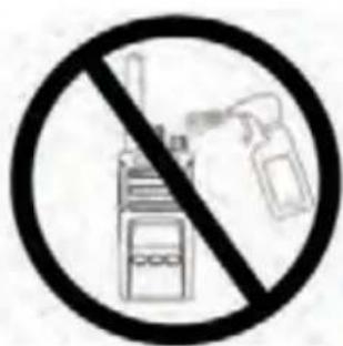
| Maintenance | Clean with a soft damp cloth, do not immerse, avoid alcohol and detergents |
| Replacement parts available | Battery, charger, case, programming cable (sold separately) |
| Repairability | Charger not serviceable, repair by authorized Motorola service |
| Included accessories | Drop-in charger, power supply, regional adapters, case |
| Programming software | CPS downloadable at www.motorolasolutions.com |
| Weight | Approximately 250 g with battery (estimated) |
| Dimensions | Approximately 130 x 60 x 35 mm (estimated) |
| Operating temperature | 0 °C to 40 °C (estimated based on charger) |
Frequently Asked Questions - XT460 ZEBRA
User questions about XT460 ZEBRA
0 question about this device. Answer the ones you know or ask your own.
Ask a new question about this device
Download the instructions for your Radio in PDF format for free! Find your manual XT460 - ZEBRA and take your electronic device back in hand. On this page are published all the documents necessary for the use of your device. XT460 by ZEBRA.
USER MANUAL XT460 ZEBRA
Batteries and Chargers Safety Information 3
Operational Safety Guidelines. 3
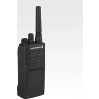
Radio Overview 4
Parts Of The Radio 4
On/Off/Volume Knob. 5
Microphone 5
Antenna. 5
Accessory Connector 5
Model Label 5
LED Indicator 5
Front Buttons 5
Side Buttons 6
Batteries and Chargers. 7
Installing the Lithium-Ion (Li-Ion) Battery 7
Removing the Lithium-Ion (Li-Ion) Battery 7
Holster. 7
Power Supply, Adaptors and Drop-in Tray Charger . .8
Charging with the Drop-in Tray Single Unit Charger. .9
Charging a Standard Battery 9
Drop-in Tray Single Unit Charger LED Indicators . . . 10
Getting Started 11
Turning Radio ON/OFF 11
Adjusting Volume 11
Reading The Display. 11
Selecting A Channel 11
Talking And Monitoring 11
Talk Range 12
Reset To Factory Defaults. 14
Programming Features 15
Entering Programming Mode. 15
CPS (Computer Programming Software). 15
Use And Care 17
SAFETY
PRODUCT SAFETY AND RF EXPOSURE COMPLIANCE

Caution
Before using this product, read the operating instructions and RF energy awareness information contained in the Product Safety and RF Exposure booklet enclosed with your radio.
ATTENTION!
This radio is restricted to occupational use only to satisfy ICNIRP/FCC RF energy exposure requirements.
For a list of Motorola-approved antennas, batteries, and other accessories, visit the following website which lists approved accessories:
http://www.motorolasolutions.com
BATTERIES AND CHARGERS SAFETY INFORMATION
This document contains important safety and operating instructions. Read these instructions carefully and save them for future reference.
Before using the battery charger, read all the instructions and cautionary markings on
the charger,
the battery, and
the radio using the battery
- To reduce risk of injury, charge only the rechargeable Motorola-authorized batteries. Other batteries may explode, causing personal injury and damage.
- Use of accessories not recommended by Motorola may result in risk of fire, electric shock, or injury.
- To reduce risk of damage to the electric plug and cord, pull by the plug rather than the cord when disconnecting the charger.
- An extension cord should not be used unless absolutely necessary. Use of an improper extension cord could result in risk of fire and electric shock. If an extension cord must be used, make sure that the cord size is 18AWG for lengths up to 6.5 feet (2.0m) and 16AWG for lengths up to 9.8 feet (3.0m) .
- To reduce risk of fire, electric shock, or injury, do not operate the charger if it has been broken or damaged in any way.
Take it to a qualified Motorola service representative.
- Do not disassemble the charger; it is not repairable and replacement parts are not available. Disassembly of the charger may result in risk of electrical shock or fire.
- To reduce risk of electric shock, unplug the charger from the AC outlet before attempting any maintenance or cleaning
OPERATIONAL SAFETY GUIDELINES
- Turn the radio OFF when charging battery.
- The charger is not suitable for outdoor use. Use only in dry locations/conditions.
- Connect charger only to an appropriately fused and wired supply of the correct voltage (as specified on the product).
- Disconnect charger from line voltage by removing main plug.
- The outlet to which this equipment is connected should be nearby and easily accessible.
Maximum ambient temperature around the power supply equipment must not exceed 40^ (104^) - Make sure that the cord is located where it will not be stepped on, tripped over, or subjected to water, damage, or stress.
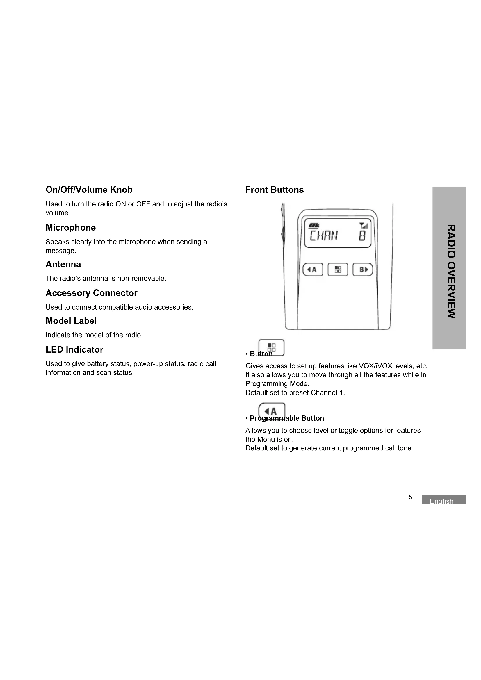
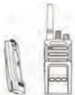
RADIO OVERVIEW
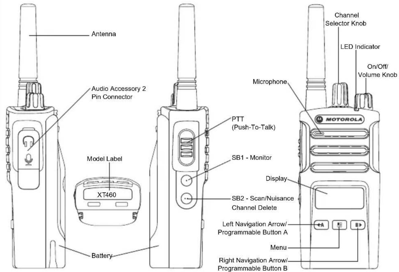
PARTS OF THE RADIO
On/Off/Volume Knob
Used to turn the radio ON or OFF and to adjust the radio's volume.
Microphone
Speaks clearly into the microphone when sending a message.
Antenna
The radio's antenna is non-removable.
Accessory Connector
Used to connect compatible audio accessories.
Model Label
Indicate the model of the radio.
LED Indicator
Used to give battery status, power-up status, radio call information and scan status.
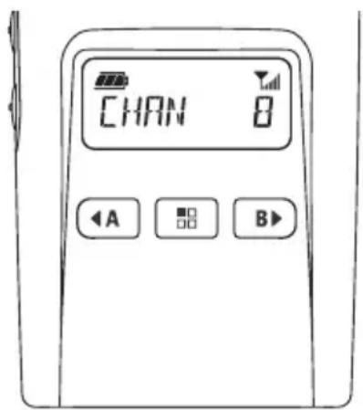
Front Buttons


Gives access to set up features like VOX/iVOX levels, etc. It also allows you to move through all the features while in Programming Mode. Default set to preset Channel 1.

Allows you to choose level or toggle options for features the Menu is on. Default set to generate current programmed call tone.
B
- Programmable Button
Allows you to choose level or toggle options for features the Menu is on.
Default set to Backlight Mode.
Note: A short press of either Programmable Button (A or B) tunes the radio to the preset channel and the radio will play a good chirp. You can assign different functions to these buttons via the CPS. For example: Backlight Time Out, Reverse Burst, Scan/Nuisance Channel Delete, Monitor and Call Tones. To learn more about how to program these buttons, refer to "Entering Programming Mode" on page 15 and "CPS (Computer Programming Software)" on page 15.
Side Buttons
- Push-To-Talk (PTT) Button
Press and hold down this button to talk, release it to listen.
- Side Button 1 (SB1)
The Side Button 1 is a general button that can be configured by the CPS. Default set to Monitor Mode.
- Side Button 2 (SB2)
The Side Button 2 is a general button that can be configured by the CPS. Default set to Scan/Nuisance Channel Mode.
BATTERIES AND CHARGERS
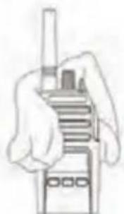
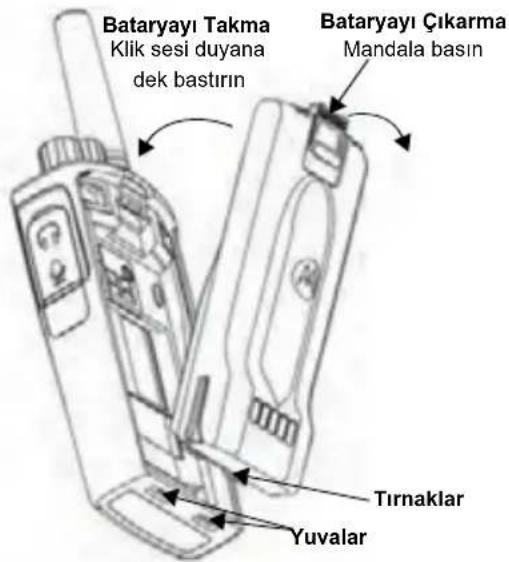
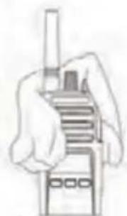
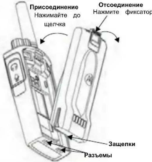
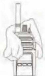
Installing the Lithium-Ion (Li-Ion) Battery
- Turn OFF the radio.
- With the Motorola logo facing up on the battery pack, insert the tabs at the bottom of the battery with the slots at the bottom of the radio's body.
- Press down on the battery, top first, towards the radio until a click is heard.
Removing the Lithium-Ion (Li-Ion) Battery
- Turn OFF the radio.
- Push down the battery latch and hold it depressed while removing the battery.
- Pull the battery away from the radio.
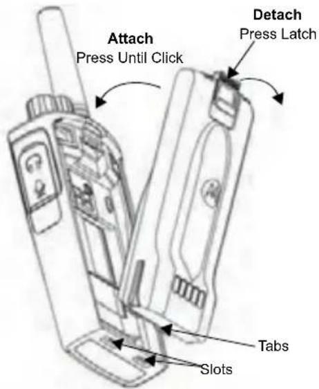
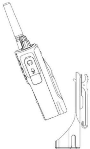
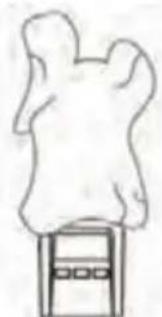
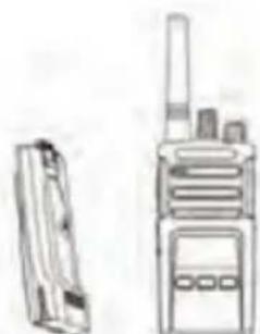
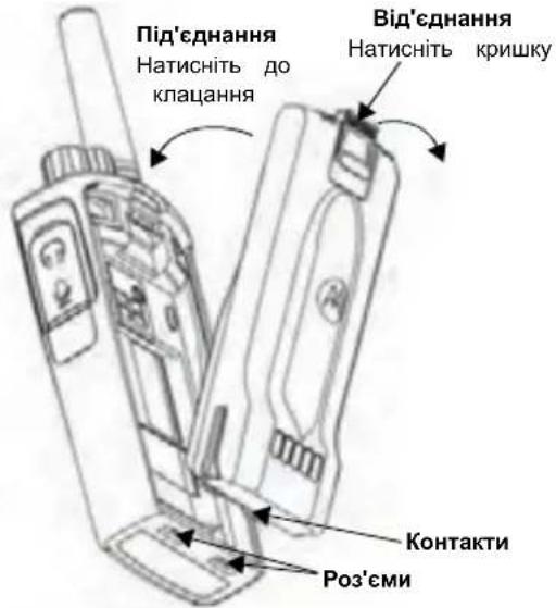
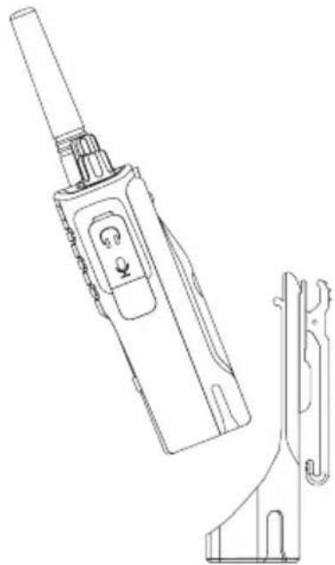
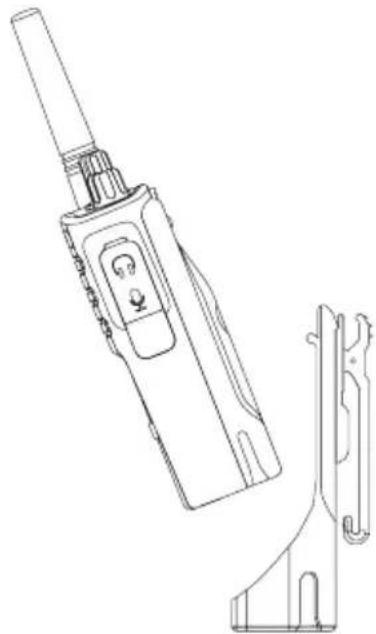
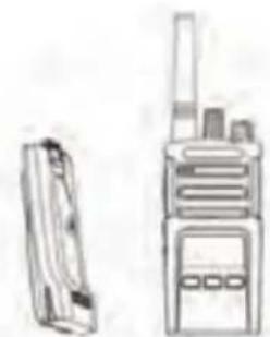
Holster
XT420 and XT460 will be coming with Holster instead of Belt Clip to improve the wearability.
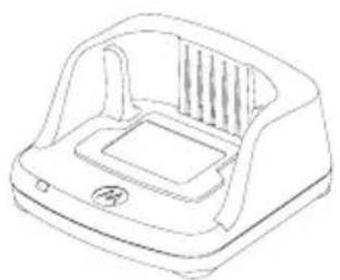
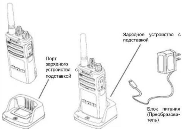
Power Supply, Adaptors and Drop-in Tray Charger
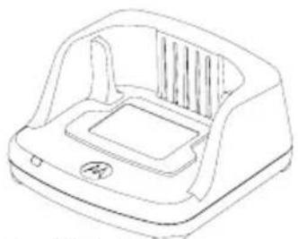
Drop-in Tray Charger
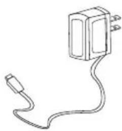
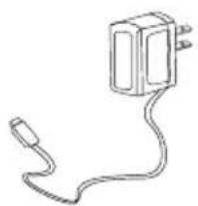
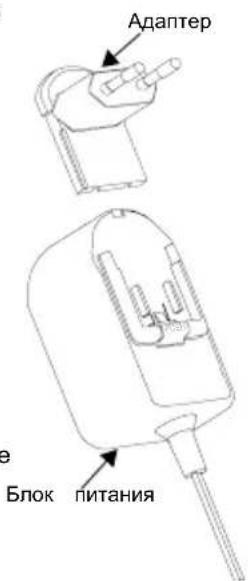
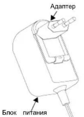
Power Supply
Your radio comes with one Drop-in Tray Charger, one Power Supply (also known as Transformer) and a set of adaptors.
Your Power Supply is capable of switching to suit any of the adaptors that comes with your radio package.
The Adaptor you install depends on the region you're located.
Once you have identified the Adaptor that matches your electrical outlet, proceed to install it as follows:
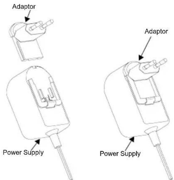
- Slide down the Adaptor grooves into the Power Supply until it snaps into place.
- Slide the Adaptor upward to remove.
Note: The adaptor shown in the pictures are for illustration purposes only. The adaptor you install may be different.
When acquiring additional Charger or Power Supply, make sure you have the similar Drop-in Tray Charger and Power Supply set.
Charging with the Drop-in Tray Single Unit Charger
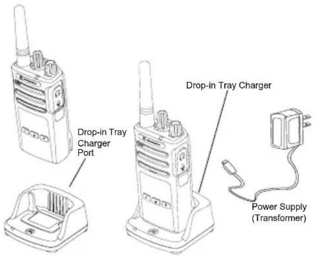
- Place the Drop-in Tray Single Unit Charger on a flat surface.
- Insert the connector of the Power Supply into the port on the side of the Drop-in Tray Single Unit Charger.
- Plug the AC Adaptor into a power outlet.
- Insert the radio into the Drop-in Tray Single Unit Charger with the radio facing the front, as shown.
Note: When charging a battery attached to a radio, turn the radio OFF to ensure a full charge. See "Operational Safety Guidelines" on page 3 for more information.
Charging a Standard Battery
The Drop-in Tray Single Unit Charger is designed to charge either the battery (with the radio or with radio and holster on) or a standalone battery.
Table 1: Motorola Authorized Batteries
| Part Number Description | |
| PMNN4434_R Standard Li-Ion Battery | |
| PMNN4453_R High Capacity Li-Ion Battery |
Drop-in Tray Single Unit Charger LED Indicators
Table 2: Charger LED Indicator
| Status LED Status Comments | ||
| Power On Green for approx. 1 | sec | |
| Charging Steady red | ||
| Charge Complete Steady green | ||
| Battery Fault (*) | Red fast flash | |
| Waiting to charge (**) | Amber slow flash | |
| Battery Level Status | Flash red 1 time | Battery low |
| Flash amber 2 times | Battery medium | |
| Flash green 3 times | Battery high | |
(^) Normally, re-positioning the battery pack will correct this issue.
(^*) Battery temperature is too warm or too cold or wrong power voltage is being used.
If there is NO LED indication:
- Check if the radio with battery, or the battery alone, is inserted correctly.
- Ensure that the power supply cable is securely plugged into the charger socket.
- Confirm that the battery being used with the radio is listed in Table 1.
GETTING STARTED
For the following explanations, refer to "Parts Of The Radio" on page 4 of the user guide.
To turn ON the radio, rotate the ON/OFF/Volume Knob clockwise. The radio plays one of the following:
- Power up tone and channel number announcement, or
- Battery level and channel number announcements, or
- Silent (Audible tones disabled)
The LED blinks red briefly.
To turn the radio OFF, rotate the ON/OFF/Volume Knob countercase until you hear a 'click' and the radio LED indicator turns OFF.
ADJUSTING VOLUME
Turn the ON/OFF/Volume Knob clockwise to increase the volume, or counterclockwise to decrease the volume.
Note: Do not hold the radio too close to the ear when it is at a high volume setting or when adjusting the volume setting.
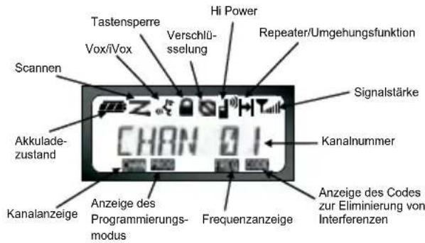
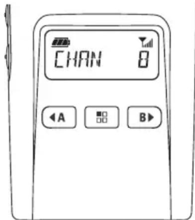
READING THE DISPLAY
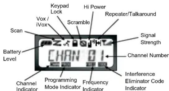
Note: The radio display shown here is for icon location only. Each radio display may appear different (channel and code) based on the pre-programmed radio defaults and features available in the model or region. Pressing any button, except the PTT button, will turn on the backlight.
SELECTING A CHANNEL
Use the Channel Selector Knob to access a specific channel.
During powering on or switching channel, the voice annunciation will confirm the channel number.
Program each channel separately. Each channel has its own Frequency, Interference Eliminator Code and Scan Settings.
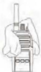
TALKING AND MONITORING
It is important to monitor for traffic before transmitting to avoid 'talking over' someone who is already transmitting. To monitor, press and hold the SB1(*) button to access channel traffic. If no activity is present, you will hear 'static'. To release, press the SB1 button again. Once channel traffic has cleared, proceed with your call by pressing the PTT button. When transmitting, the radio LED will be solid red.
Note: In order to listen to all activities on a current channel, short press the SB1 button in order to set the CTCSS/DPL code to 0. This feature is called "CTCSS/DPL Defeat (Squelch set to SILENT)".
(*) This assumes SB1 button has not been programmed for a different mode.
RECEIVING A CALL
- Select a channel by rotating the Channel Selector Knob until you reach the desired channel.
- Make sure the PTT button is released and listen for voice activity.
- The LED Indicator blinks RED while the radio is receiving a call.
- To respond, hold the radio vertically 1 to 2 inches (2.5 to 5cm ) from mouth. Press the PTT button to talk; release it to listen.
Note: Please note that when radio is receiving or transmitting, LED is always RED.
Note: Interference Eliminator Codes are referred also as CTCSS/DPL codes or PL/DPL codes
TALK RANGE
XT Series radios have been designed to maximize performance and improve transmission range in the field. It is recommended that you do no use the radios closer than 1.5 meters apart, to avoid interference. XT460 coverage is 16.250 square meters, 13 floors and 9 KM in flat areas.
Talk range depends on the terrain. It will be affected by concrete structures, heavy foliage and by operating radios indoors or in vehicles. Optimal range occurs in flat, open areas with up to 9 kilometers of coverage. Medium range occurs when buildings and trees are in the way. Minimal range occurs when dense foliage and mountains obstruct the communication path.
To establish a proper two-way communication, the Channel, Frequency and Interference Eliminator Codes
must be the same on both radios. This depends on the stored profile that has been pre-programmed on the radio:
- Channel: Current channel that the radio is using, depending upon radio model.
- Frequency: The frequency the radio uses to transmit/ receive.
- Interference Eliminator Code: These codes help minimize interference by providing a choice of code combinations.
- Scramble Code: Codes that make the transmissions sound garbled to anyone listening who is not set to that specific code.
- Bandwidth: Some frequencies have selectable channel spacing, which must match other radios for optimum audio quality.
For details of how to set up frequencies and CTCSS/DPL codes in the channels, refer to "Entering Programming Mode" on page 15
RADIO LED INDICATORS
| RADIO STATUS LED INDICATION | |
| Channel Alias Edit Red heartbeat | |
| Cloning Mode Two Orange Heartbeats | |
| Cloning In Progress Solid Orange | |
| Fatal Error at Power up | One Green Blink, One Orange Blink, One Green Blink, then repeat for 4 seconds |
| Low Battery Orange Hearbeat | |
| Low Battery Shutdown Fast Orange | Heartbeat |
| Monitor LED is OFF | |
| Power-Up Solid Red for 2 seconds | |
| ‘Idle’ Programming Mode /Channel Mode | Green Heartbeat |
| Scan Mode Fast Red Heartbeat | |
| Transmit (Tx)/Receive (RX) Solid Red | |
| Transmit in Low Power Select Solid | Orange |
| VOX/iVOX Mode Double Red Heartbeats | |
Note: Channel Alias Edit only applies to Display Models
Reset To Factory Defaults
Reset To Factory Defaults will set back all radio features to the original factory default settings. To do so, press the PTT, SB1 and SB2 button simultaneously while turning ON the radio until you hear a high tone chirp beep.
PROGRAMMING FEATURES
Entering Programming Mode
Programming Mode is special radio mode that allows you to program basic radio's features by using the radio's panel programming.
To enter Programming Mode, press and hold the PTT Button and the SB1 Button simultaneously for 3 seconds, while turning ON the radio. A unique tone sounds, indicating the radio has entered Programming Mode. The radio LED blinks a green heartbeat.
Note: The default Programming Mode is set to 'Idle' Programming Mode.
When the radio is set to Programming Mode, the icon displays and the current channel aliasing name blinks to indicate that you can rotate the Channel Selector Knob to select the channel you want to program.
In Programming Mode, the radio is capable of setting values for each channel by toggling between the different programming modes available:
-Frequencies,
-CTCSS/DPL codes (Interference Eliminator Code),
-Scramble,
Bandwidth,
Maximum Channels,
- Call Tone,
- Microphone Gain and,
-Scan.
- To move along the different Programming Selection Mode without saving changes, short press the PTT Button or Button.
- To save changes, long press the PTT Button. The radio returns to 'Idle' Programming Mode.
- When in 'Idle' Programming Mode, long press the PTT button to exit the Programming Mode.
- Whenever you wrap around to the beginning of the Programming Mode options, the radio automatically saves all changes made, even if you turn OFF the radio.
- Exit the Programming Mode without saving changes (as long as you have not wrap around to the beginning of the Programming Mode options) by turning OFF the radio.
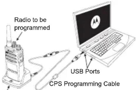
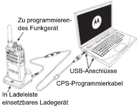
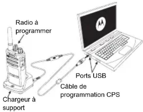
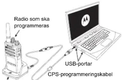
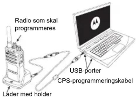
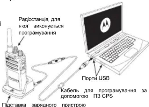
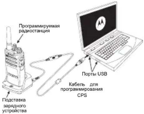
CPS (COMPUTER PROGRAMMING SOFTWARE)
Drop-in Charger Tray
XT Series radios are programmable using the CPS. The CPS is downloadable for free at www.motorolasolutions.com.
CPS allows the user to program Frequencies, PL/DPL codes as well as other features such as Direct Frequency Input, Repeater/Talk Around, Select, Time-Out Timer, Power Select, Battery Type Select, Scan List, Call Tones, Scramble, Reverse Burst, etc.
CPS is a very useful tool as it can lock the frontpanel radio programming or restrict any specific radio feature to be changed (to avoid preset radio values to be accidentally erased).
It also provides security by giving the option to set up a password for profile radio's management. Please refer to Features Summary Chart Section at the end of the User's Guide for more details.
Note: (*) CPS Programming Cable is an accessory sold separately. For part number information, refer to the Accessories Section.
See CPS CD for detailed information on CPS.
USE AND CARE
Use a soft damp cloth to clean the exterior

Do not immerse in water Do not use alcohol or
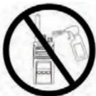
cleaning solutions
If the radio is submerged in water...
Turn radio OFF and remove batteries
Dry with soft cloth Do not use radio until

completely dry
Notes
MOTOROLA, MOTO, MOTOROLA SOLUTIONS and the Stylized M logo are trademarks or registered trademarks of Motorola Trademark Holdings, LLC and are used under license. All other trademarks are the property of their respective owners.
© 2013 Motorola Solutions, Inc. All rights reserved.
INHALT
Inhalt. 1
Sicherheit. 2
CPS (Computer Programming Software). 16
ABLESEN DES DISPLAYS
CPS (COMPUTER PROGRAMMING SOFTWARE)
CPS (Computer Programming Software). 15
MISE SOUS TENSION/HORS TENSION DE LA RADIO
RéCEPTION D'UN APPEL
CPS (COMPUTER PROGRAMMING SOFTWARE)
CPS (Computer Programming Software). 15
CPS (COMPUTER PROGRAMMING SOFTWARE)

Base dearga
Software CPS (Computer Programming Software) 16
Pulsante PTT (Push-to-Talk)
SOFTWARE CPS (COMPUTER PROGRAMMING SOFTWARE)
DESLIGUE o Radio e remova as baterias
- Knop Push-to-Talk (PTT)
- PPT-knap (Push-To-Talk)
JUSTERING AF LYDSTYRKEN
CPS (Computer Programming Software). 15
- PTT-knapp (Push-To-Talk)
CPS (COMPUTER PROGRAMMING SOFTWARE)
Laddare med fack
Etuosan painikkeet 5
Sivupainikkeet. 6
Akut ja laturit 7
Lithiumioniakun asentaminen 7
Lithiumioniakun irrottaminen. 7
Kotelo 7
CPS (Computer Programming Software). 15
- PTT-knapp (Push-to-Talk, trykk for a snakeke)
CPS (COMPUTER PROGRAMMING SOFTWARE)
Lityum-Iyon (Li-Ion) Bataryayi QiKarma 7
Tutucu. 7
Guc Kaynagl,Adaptorler ve Sarj Cihazi Tepsisi. .8
Lityum-iyon (Li-Ion) Bataryayi Takma
Lityum-iyon (Li-Ion) Bataryayi Çıkarma
- Telsizi KAPATIN.
- Bataryayi cikarirken batarya mandalini bastirarak asagiro dogru itin.
- Batayayi telsizden ickarin.
Tutucu
- Przycisk Push-to-Talk (PTT)
CbitIOIOHn iHdkaTOp. .5
IpeepHi KhoNKn 5
BiHi KhoNKn 6
Akymylantopn Ta 3aprHi npncptoi 7
BctaHOBJeHHJIiHIOHHORLi-Ion)
akymyIaTopa. 7
BnMaHnHaJIiI-IoHHoro (Li-Ion) akymyIaTopa. . . .7
Yoxon 7
BLOKXIBJeHHa,aaanTeepTa3apdHn npucpti 3
πiπCTaBkoIO 8
3apxkanHH 3a donomoro oHOMichoro 3apnHO
npntpo 3 ndTaBko1.9
3apJxKaHHaKMyIyTopa CTaHdApTHoI EMHOCTI 9
CbitnoioHi iHdkaTopn 3apdHoro npncptpoi i3
JOTKOM Ha oDINH npicTpii 10
PiIroTobKa do po6oTu 11
BMUKAHH/BNMUKAHHpaiaoctauui 11
PerylIOBaHHr rUHocTi. 11
Ioka3aHHn DnCnner 11
Bn6ip paiokaHaIy 11
PpHOM BnKNIky 12
ДаьнICTь ВИКПИКу. 12
CbitnojioHi iHnkaTopu paioctanii 13
BidHOBHeHH CTAHapTHnx HanaTuBaHb 14
IporpaMOBaHi 4yHKuii 15
Pepexid do peximy nporpaMyBaHHa
KOMN'IOTePHe IporpamHe 3a6e3neueHHa CPS .15
Ecknlyataui Ta dorgna 17
BIDOMOCTI ⅢODo B3NEKN
BIDIOBIHICTb PPOyKTY BUMOTAM ⅢOIO BE3NEKN TA PAIOUCACTOTHOBOBIPOMIHOBAHNRA

3actepexhenn
Ipeed BnKOpNCTaHHM cBoro Bnpo6y npoHTaTe cei noci6Hnk i3 ekpnyataii Ta 03HaHOMTecra 3 BiOMOCTMaN OODO pIBHpaioactOTHO BnPOMIHOBAHNA HabeDeHMN B 6poUpyi «Be3neuHicTB Bnpo6y Ta pIBHi paioactOTHoro BnPOMIHOBAHRA》,IO BXODNTb DO KOMJIeKTy padionpncTroH.
YBAGA!
BiinobiDnO do BnMOr ΦeepaIbHoI KOMici 3i 3B'3Ky (CUSA) zoDo pIBHIB paioyactOTHO RINpOMiHOBaHHa, ue npicptpi npn3HaueHn BKNIOUHO dna npoceciHoro BIKOPNCaHHa.
IpepiKaHTeH, AkymyJIAToPiB Ta iHuaX akceCyapiB, CXBaJIeHIX KOMnaiHcIeO Motorola, Hb. Ha Be6-caNti:
http://www.motorolasolutions.com
IHΦOPMAU3 3 TEXHIKN BE3NEKN PPN POBOTI 3 AKUMYJIATOPAMN TA 3APYHNMN IPNCTPOAMN
Lcien DOKyMeHt MicNTb BaxKnBi IHCTpyKuIi 0do 6e Ta ekCnIyatauii. YBaXHo npOHTaIe Tc i HCTpyKuIi Ta 36epexitb ix nna noJaIbUoro BNKOpNCtAHN.
Ipeed noaTkom BnKOpncTaHH 3apdHoro npntpoAkyMnyTopo O3HaOMTeC8 3 ycima iHCTpyKciamu Ta nonepdxKyBaJIbHMn No3Haaykamn Ha
3aprHOMy npucTpoi,
akymyntopi Ta
Ha paioctaui, npaue Bid akymyTopa
- Ⅲo63MeHnHTn pni3NK yIkoKxHb, BIKOpNCToByTe TINbKn akymyJrTopn, CXBaJIeHI KOMnaHicIO Motorola. IHIa akymyJrTopn E BIn6yXOHe6e3NeuHHMn Ta MoKyTb cnPnHnHTn TpaBMn Ta MaTepiJIbHi 36NTKn.
- BnKOpncTaHnAkceCyapIb, He peKOMeHDoBaHnx KOMNaHieO Motorola, MoKe npu3BecTn Do 3aImaHn, ypaXeHH eJekTpUHMM Ctpymom a6o TpaBMyBaHn.
-
- yHnKHyTN yHKoJxHeHn enektpuHoi BnKn Ta npOy, npn BiKIOeHHI 3apdHoro npncptpoB iD po3eTK T3a BNky, a He 3a dpit.
4.BnKOpNCTaHHNoDObKyBaHa Do3B0JrEbC8nIuue y paai KpaHbOHeo6xIDHOCTi.BnKOpNCTaHH NoDObKyBaHa,IO He BiINOBiDae BmORM,MOKe CTaTN pNpHHIO 3aIMaHH a6o ypaXeHHNeEkeTpNHcM CTPyMOM. JkIo BnKOpNCTaHH NoDObKyBaHa e Heo6xIDHM,nepeKoHaIteC8,IO BnKOpNCTobByeTbCra pIT KIacy 18 AWG 3a DOBxHN Do 2,0 M (6,5fytB),Ta 16 AWG 3a DOBxHN Do 3,0 M (9,8fytB).
- yHnKHyTN yHKoJxHeHn enektpuHoi BnKn Ta npOy, npn BiKIOeHHI 3apdHoro npncptpoB iD po3eTK T3a BNky, a He 3a dpit.
-
3mEHnTn p3nK 3aHaHHy, ypaKeHH eEeKTPuHm CTpyMOM a6o TpaBMvBaHH, He BkOpNCTOByTe HecnpabHi a6o ykoJKeHi 3apdHi npCTpoi. IpeJaTe ix do ceptnФikOBaHOro npedCTabHnTBA kOmnaH iMotorola i3 cepBicHoro o6cnyroByBaHH.
-
He po3bupaTe 3apdHn npucTpi; Bin He niDnae peMOHTy Ta 3amHI HecnpabHNx qactnH. Po3bupaHHra 3apdHoro npucTpoIO NOB'3aHe i3 pu3NKOM ypaXeHHra eNEKtpuHm CTpyMOM Ta 3aiMaHHra.
-
7.06 3MeHUNr pN3NK ypaXeHHa eNeKtpuHNM cTpymOM, nepei npOBeHnM 6yD-b-axx onepauij 3 TexHiHoro 06cnyroByBaHHa a6o OunIeHHa BiJkIIOuaTe 3apAHDn npicTpi BID po3ETKn 3MIHHORO cTpmy.
IHCTPYKLI3BE3NEUHOI EKCNIYATAL
-Пд часзарджаннakумлгета ВIMКайтepaionpncpti.
- 3apdHn npictpi He np3NaeHn dIy BIKOpNCTaHH npocTo He6a. BIKOpNCTOByTe Ioro NIIe B cyxnx npimUeHNx/yMOBax.
Плкюаite 3apdн npncpti Jnwe do dpoTOBnx DkepeJ XNBHeHna KaNX HaJeXHM YNHOM BCTaHOBNeHO IJaBki 3anobixKHNi, i3 BiNIOBIDHM pIBHEm Hanpyr (K BKa3aHo Ha npOdykTi).
-Дя BiДКПIOHENH 3apIaHOrO npIcTpoI BID MEpeXHOi HAnpyrBn BITraHrHbIb rToIOBHN pO3'EM 3 po3eTK.
Ib Po3eTKa,do JAKOIpiKIIIOHaEcTBcA CE o6JIaDHaHHa,MaE 3hAxODHTncNpOpyu, yJeRKOdCTynHOMyMiCi.
- MakcimalbHa TemnepaTypa oTochyUOHoro cepedobuza DkepeNa KINBJIeHH He noBHHa nepeBnUyBaTn 40°C (104°F).
ДрIT NOBINH6ByTNpo3aUOBAHnB TaKOMyMiCTI,DE BKNIOuHaεTbCnYO KONTaKT i3 BOIO,UYKOJKeHHa 60 TnCK,Ta De Ha HbOro HEmOXJIbBO HaCTyNtN a60 nepeuenNTncr Ypee3 HbOrO.
HaKneiKa 3 Ha3BOIO MoJeI
Bka3ye MoDJIb paioctaHui.
CbitIIOiOHH iHdkaTOp
Pn3HaueHnn DnB iDobpaKeHHa CTAHy aKyMyJrTopa, CTaHy paIOCTaHui (yBIMKHeHH/BIMKHeHH), CTaHy paIOBKNIKy Ta CTAHy cKaHyBaHH.
IpeepHi KhoNKn

Lc KhONka Hadae DocTyn Do BCTaHOBNeHH TaKHX npametpiB, k piBeHb VOx/IOX ta iHwe.
Boha TakoK Do3B0JNe nepexOuNTn BiD npapaMeTpa Do npapaMeTpa B peKIMI nporpaMyBaHH.
3a 3AMOByBaHHnHaJaUToBaHa Ha nonepdHbO HajaTuBoAHn KaHn1.

D03B0JRE Bn6upatn pibehb a6o nepemiuataHc MIX OIJIaM NII NOTOUYHX FyHKui MeHIO.
3a 3amOByBaHHa HanaWToBaHa Ha BiTbOpeHHa NTOUHO 3anporpamOBaHO TOHaJIbHO BUKNIky.
-Поррмован KaONKa
D03BONRA Bn6upaTH pibehb a6o nepeMiaatncra MIX ONiIMN DnI NOTOCHNX FyHKui MeHIO. 3a 3AMOBuYBaHHa HanaWTOBaHa Ha peXm NiDCBIyBaHHa.
Ппмітka.KopoТke HATNCKaHЯ ODiHiei 3 nporpamOBaHnx KHOJOK (A a6o B) HanaSTOBye paioctanuio Ha nonepeDhbo BCtaHOBHeHn KaHAN, i paioctanuia BiIDTBOpHc MeNoiHn 3ByKOBn CnHaN. 3a DonomoroIOI3 CPS dIy KHOJOK MOXHa BCTaHOBHTn pi3Hi FyHKUII. HanpNKlaI: Yac BmKHeHHra NiCbiYBaHnR, Reverse Burst, CkaHyBaHn/BlaIeHHra HebaxaHx KaHAnIB, MoHITopINr a6o ToHaJIbHI BVKnIKn. DoklaNDiSe npo nporpaMyBaHHra XIX KHOJOK IDeTbcra Ha cTOp. «Ipeexid do peximy nporpaMyBaHHra» Ha cTOp. 15 ta «Kom'HoTePhe nporpaMHe 3a6e3neueHHra CPS» Ha cTOp.15.
BiyHi KHONK
- TaHreHTa PTT (Push-to-Talk - aHRn. «HaTncHn-TaTogOpu»)
IЯ nepeaichi NOiDMJIeHHHaTNCiHb Ta yTpmyTe TaHTREHTy,ДЯ npocnyxOByBaHHa-BiDnCyTiB.
- BiiHa KhoNka 1 (SB1)
BiHa KNHka 1 e KHONKO 3aRaIbHoro npn3NaeHHra Ka HanaTObYcTBcra 3a DonomoroIO I3 CPS. HanaTByBaHHra IINKHN SB1 3aAMOBHyBaHHr - «MoHiTopnIHr
- BiuHa KhoNka 2 (SB2)
Biyha KhoNka 2 € KhoNkoIO 3araIbHoro npn3HaueHHra Ka HanaTobByeTbcra 3a Donomor6 CPS. HanaTsyBaHHra DnI KhoNk SB2 3a 3amOByBaHHm - «CkaHyBaHHra BuaJaleHHra He6axaHnx KaHaJIb
AKUMYJIATOPN TA 3APJHII PNCPTPOI
BcTaHOBJIeHHa NiTiH-oHHoro (Li-Ion) akymyIaTopa
1.BIMKHITb paioctahuiio.
2. Po3auyte akymyIaTOPHn Bicik norotinom Motorola Doropu Ta 3ictaBTE KOHTAKn B HxKHi qactnHi akymyIaTopa i3 KOHTaTAMn BHn3y Ha Kopnyci paiaocTaHii.
- Nounhaon 3 BepxHbO KpaIO,do KnaaHn npTnCHITb aymyIaTOP do paioctanii.
BnMaHnI niTi-iOHHoro (Li-Ion) aKymyJTopa
- BIMKHITb paioctanuio.
2.3cyHbTe KpUkky akyMyJrTopa Bn3. - Tpmaohny Kpuuky npunchcyto, BuTnHITb akymyIaTOp i3 paoiOCTAHii.
Qoxon
XT420 Ta XT460 Bnnyckatmybcr i3 0xIOM 3amictb noarhoi klincn dna 6nbkomfoptHoro HocHHra.
CunHan yBIMKHeHH npnctpoTa oronoWeHH Homepa KaHany
OronouenHH pIBH 3apny akymyIaTopa Ta HOMepa KaHany
Be33ByHn (ayioocnHaHn He BiTbOpIOHTbcra)
CbitnoioiHn iHdkatop DeKn Yac 6nMaTMe UepBOHM.
UoB BMKHytn paioctaHciIO, noBepHb tyky «YBMK./ BIMK./TyHictb> npOT roHHNKOBOc tCPIKN dO KnaCaHHn, npu cblomy CBITIOIDHN iHdkaTOp BMKHeTcbra.
PERYJIIOBAHNAI IYUHOCTI
PoeptaTe pyky «YBIMK./BMK./TyHicTb» 3a roHHNKOBIO CTpiIKO, 66 36iNbWHTn rYHicTb, Ta npOTn roHHNKOBOI CTpiIKN, 66 3MeHwNTn ii.
Ppimtka. Pn nBmuehi ryHocT Ta n iac peryIOBAHHryHocHe TpmaTe paioctauuho HADTo 6n3bko Do Byxa.
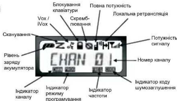
PpimtKa.36paKeHHaDCnHeo paIOCTaHua HabeEHO Nue Kocti iIOCTpaui po3MiueHH CNMBOIB Ha HbOMy.
Dicnnei paioctaHui MoKe Bipi3Hrtnc BId 3o6paKeHoro Ha iIOCTpaui (KaHaI Ta KoI MOKyTb 6yTN iHUnMn),B 3aJIeKHOCTi BiHanepeI
3anporpamOBaHn HanaHTyBaHb paioctHaii 3a 3AMOByBaHHa, a TAKOX BID xapakTePncTK moJeI Ta OcO6nBocTei perioHy. Pn HATNCKaHHi 6yDb-koI KHONK, OKPIM TaHREHTN PTT, BMNaactbcra NiDCBiyBaHHa.
Bn6IP PADIOKAHJY
I06Bn6paTn notpi6Hm KaHaJ, cKOpNCtYntecra pyKoO Bn6opy KaHanib.
IiD yBIMKHeHH paionpncToHO Ta nepeMnKaHH KaHJIIB Homep KaHany nITBepdKyetybcr roJIOCBIM NOBIOMNEHHM.
KoKHi KaHaI npOrpamyetybCg OkPcMo.ДЯ KoKHO KAHaJY BCTAHOBJIIOETbC CBOR YACTOTa, KOD
Wymo3aIyUeHH Ta HalaTsyBaHH CkaHyBaHH.
OBMIH IOBIIDOMJIENHHaMIMAMOHITOPINH
Baxnbo npoBecTu MOHITOPnHr ephipy nepeD NOaTkOM
po60Tu, 106 nepeKoHaTnC, 10BaUe cnIkyBaHHn He
HaKnlaDatmMetbCn Ha nepeDauy iHooi paIOCTaHcii.
TnnepeBipKn HauBHOcti TpaFiky B cBomy KaHani
HaTNCHT Ta yTpIMyTe KONky SB1(*).3a BiDCyTHOcTi
paioo6miHy 6yde yTHO CTaTNHi 3abAn. HatncHtB
KhONky SB1 1ue pa3 ta BiIDnyCTiB ii, 106 3abepuNTn
MOHITOpHR. 3a BiDCyTHOcTI TpaFiky B cBomy KaHani
BVKOHaTe BnKNK, HATNCHyBUn TaHReHTy PTT. Nid Yac
nepeDaY CBITNoiOHDnIH INdNKaTOp paIOCTaHcii 6yde
noCTiHo YepBOHmM.
Ппмітka.лбпocухати BCоakTbHcTB b cboMy kaHani, KopoТКо HATnCHITb KONky SB1 Ta BCTaHOBITb ДЯ CTCSS/DPL 3haeHnRA «0').LЯФнкян ha3nBaetbcr «Bidmiha CTCSS/DPL》(3aInyuHnR 3aBaD BiKlnOuaTeCbca).
(*) 3a yMOBn, uO KhONky SB1 He 6yNo nepenporpamOBaHO Ha iHuy _YHKUIO
ПРИСМВКЛИКУ
- Bn6epiB kaHan, nobepTaIOHy pyKy Bn6Opy kaHAnIB,doKn He 3NaIdeTe noTpi6Hn.
- IpeekohaiTecra, 0o TaHReHTa PTT He HATnCHyTa, Ta npocnyxainTe roJOCoby aKTHBHCtB.
3.Пдчас npnomy cBITIOIDHIN iHdkatop 6JNMAe YepBOHIM KONboporM. - Ⅲo6 npinHn BnKInk, TpmaTe paioctaHIOBepTKaIbHo Ha BiDcTahi 2,5-5 cm BiD rYb. Ⅲo6 nepeDaTI NobIDOMJIeHHa HATNCiTB TaHReHTy PTT, Ta BiNcyCTtB II, Ⅲo6 npocnyxatn BiINobiNb
Ipnitka. 3BepHITb ybar, 0o niz cac npinomy a6o nepeaHi iHnKATOp paiaoctaHcii noctiHo CBiTbCra YepBOHM KOIbOpom.
DAJIbHICTb BNIKJINKY
MeTOO CTBOpEHnpaIOCTaHcui cepii XT MaKcMaJIbHe NOKpaUeHHE KCNlyatauHnx XapakTePncTnKa Ta niIBNueHHd aIbHOCTi 3b'3kU Ha BIDKpNTOMy npocToPi. PekomeHDoBaHa BiDCTaHb Mx paIOCTaHcuiMn Dn yHnKHeHH B3aEMHnx nepeWKoD MaC cTAHOBtN He MeHwe 1,5 MeTa. PaIyc dI Xi XT460 cknaDae 16 250 KB.M., 13 nobepxib a6o 9 KM Ha pIBHi MicceBOcTi. DaIbHicTh 3b'3kU 3aJeXHTb BId peBecpy MicceBOcTi. Ha daIbHicTh 3B'3kU BnINBaE TAKOX HARBHICr TaKHX nepeWkoD, Ra 6etoHhi KOHCTpyku, prChi 3eJIeHi HacAdKeHHa, a TAKOX BnKOpNCtAHnpaIOCTaHcui y npimiuHnI a6o TpaHCnopTi. ONImaJIbHni padiyc di CTaHOBt 9 KM Ha pIBHi BIDKpNTi MicceBOcTi. 3a HaraBHOCti 6ydIbeNb Ta depeB Ha shJaxy CnHany DaIbHicTh 3B'3kU 6yde cepeHbOIO. DaIbHicTh 6yde MiHimaJIbHOIO, RaIO Ha shJaxy nepeDaqi TpanJaOTbcra rYcti 3eJIeHi HacAdKeHHa 6o RopN. Dnra 3a6e3neHennr Raichoro 3B'3kU MIX DbOMa paIOCTaHcuiMn O6nDb a npinadm MaIOMb 6yTu HanaWTOBaHI Ha OOnIH i Toi camn KaHan, YactOTy Ta KODn Shymo3aIyruWeHH. Dnra zuBoHo Ha paIOCTaHcii cnid 3a3dAneridb 3anporpamByatn Ta 36epertn HanaWtuBaHH:
- KaHAn: NOTOHn KaHAn, 10B NKOpNCTOByEbCpaIIOCTaHHeO (B3aENKHOCTi BiD MoJeI).
- Yactota: yactota, ha kii BedeTbC npiHOM Ta nepeDaua.
- Kod wymo3aIyueHHn: nii6paBwN KOM6iHauiO Ko1B, MOxHb 3Hn3HTn pBeHb 3aBaJ.
- KoCckpeM6HOBAHH: Ui KOnu BnKOpNCTOByOTbcra n CNOTBOpeHH 3Byky NiI cac nepeaI, OTke NOBIDOMHeHH
MOXHa 3po3ymITiTbKn 3a HaBBOCTi BiNoBIDHOKOdy.
- 甲nHa cmyr: nra deaKx yactot icHyc ha6ip kaHaiB, kki MaOt b cnibnatau y dBox paioctaHjx dna 3a6e3neHHraikchoro padioo6mihy.
Дokлади Inctrpukii zuoHa nauwtybaHn yactot Ta KoDIB CTCSS/DPL nra KaHJIIB nB. y po3diN «Ipehexid o pexmy nporpaMyBaHHa» Ha cTOp. 15
PpIMtKa. KoAnuMOn3aRnyeHnHa3NbAToBcraTakOx KoJamCTCSS/DPL a60KoJamPL/DPL
CBITJIOIODHI IHINKATOPN PAIOCTAHU
BiHOBnEHcTaHdapTHnx HaJawTyBaHb
Функць «ВднOBлень STAHДAPTNHx HalaWTYBaHb» DO3BONIe BiDHOBTN BCI NOXIDHI HanaWtYBaHHra paIOCTaHcII, BCTAHOBJIeHi BIPo6hNKOM 3a 3amOByBaHHM.ДЯ BiDHOBLENH CTAHdAPTHNX HalaWtYBaHb NiJ Yac yBIMKHeHHra paIOCTaHcII ODHouACHO HaTNCHTb KHNKn PTT, SB1 Ta SB2 Ta yTPmMyTe, DOKn He NOUYeTe MeIoDiHn CnHaN BnCOKOTo ToHy.
ПОГРAMOBAHI Функци
Pepexid opexmy nporpaMyBaHHa
Pekn nporpamyBaHH e oO6bHMpeKIMom
paioctanii, 0o Do3BONJe nporpamyBatn II OCHOBH
fHKi 3a Donomoro nanei KepyBaHH.
InepeXody B peKm nporpamyBaHH nic ac
paioctanii ODHouacHO HATNCHTb TaHReHTy PTT ta
KHOnky SB1 ytpmyte ix npotarom 3cekynd. Iponyhae
oc6bHMn 3BykOBn CnHaJ, NOBIDOMNIOuHn pO Te, 0o
paioctanqie nepeuJna do peKm nporpamyBaHH
Cbitnoiohni iHdkatop 6yDnmatn NylbcyuOHM
3eJeHm CBITnom.
PpimItka.3a 3amOBuyBaHHm peKIM nporpaMyBaHHn 3HaxOdntbcry CTahi OUYBaHH.
KoIpaiaocTanjepexOuNTbdopeKIMMy
nporpamyBaHHaHDCnJIe PRO3'ABJREtbcra
BIDNOIBHn CmBON Ta 6nMaE Ha3Ba NOTOHORO
BkA3yUOnHaTe,IO,NoBepTaOHpyky Bn6Opy KaHAnib,
MOxHa Bn6patN KAHAN nporpamyBaHH.
y pekimi nporpaMyBaHH MoKHa BCTaHOBIOBaTn 3NaueHHI JI KOKHOrO KaHaIy, BNbnpaOuN cepei HaBHX pekimib nporpaMyBaHH:
- YactOTn,
KoibCTCSS/DPL (koibwymo3aIyweHH)
Ckpem6nHOBaHHa
-巾nHa CMyr,
-Makmamibha kInbKiTb KaHaJIb, - ToHantbHn BIKTNK,
Плдсиюва Мikpoфону - CkahyBaHHa.
-Дяпоруbaнг 6e3 36epehenha 3MiHeHkoKopoTkoHaTnCHiTb TaHreHTy PTT abo KhoNky
Ioo636epeTn 3mHeHHaHtCHiB TaYtpMuyTe TaHReHTy PTT. PaioctaHuaio nobepHeTcdo cTaHy oOikyBaHH peKmMy nporpaMyBaHH.
- Raio paioctaun 3haxoDntbcy y cTahi ouikyBaHHnpeKIMy nporpamYBaHHn, HATNCHT Ta TpymUte taHreHTy PTT, 06B BnTu 3 pekMny nporpamYBaHH.
- Ppi noBepHeHHI do noaTy nepeniky nicJnpoXoJKeHH BCix onui pexMy nporpaMyBaHH Bci 3mHeHH 6dy ABTomTuHNo 36epeKeHi, Habitj kUO paioctaHIO 6yde BIMKHeHO.
Bumkhybni paioctaHIO, MoKHa BnTn 3 6yDb-RAKO peKIMy nporpaMyBaHH 6e3 36epexeHH 3MHN (Akuo Bn He nobepHyncb Do noaKy, npoiuobwn Bci onii).
KOMN'OTEPHE IPOPTPAMHE 3A6E3NEUEHH CPS
KaHaIy,
Papionpncptoi cepii XT MoxHa nporpaMyBaTu 3a donomoroCPS. PporpaMHe 3a6e3neuHn CPS MoxHa 6e3KoUToBHO 3aBaHTaXHTn 3 Be6-caTy www.motorolasolutions.com.
3a donomoro nporpamhoro 3a6e3neueHHCPS moxHa nporpaMyBaTuacToTn, KOn PL/DPL, a TaKoK iHsi yHKui, a camE: npramn BBiD YacToTn, NOKaIbHa peTaHcIauia, Bn6ip uHpHn CmYtn, TaMep oBMeKeHHa cacy nepeDaqi, Bn6ip notyXhoCTi nepeDaqi, Bn6ip Tnny akymyTAtopa, npepiK cKaHyBaHHra, ToHaNbHi BKNIKN, ckpeM6JIIOBAHHa, fynkuio «Reverse Burst» Ta iHwe.
CPS e duyke 3pyHm iHCTpyMeHTOM, 0do3BOJRA
3abopOHnT nporpaMyBaHH 3 nepeHbOi naHeni a6o
obMexnMoKINBOcTi 3MiHeHH 6yDb-RAOi Bka3aHOI
fynkii (dny IonepeJKeHH BnnaKOBOrBndaJeHH
nonepeHbO 3anporpaMOBaHH HanaSTyBaHB).
Okpim TOrO, BOHO NiIbNtUe pIbeH 6e3neKn, Do3BOJIOuH BCTaHOBNIbBATn napOB dIpy npoepiIO HanaSTyBaHb paioctanii. DoknaHniuy iHopmauio MOxHa OTPMaTn y po3dini «Tabnue cyHKui» y KInci zuoro noci6nka KopncTyBaHa.
BmKHiTa paoctaHciO i BnMiTb akymyIaTOPn
PpOpiB cyXHO TKaHHoH

He KopnctyTeCpaioctaHueIO, DOKN BOHa NOBHICTHO He BnCOxHe
Приимитka
MOTOROLA, MOTOROLA SOLUTIONS i CTNI3OBaHn IJorOTn M E TopROHMn Mapkam a6o 3apeeCTPOBaHMn TOpROHMn Mapkam KOMnaHii Motorola Trademark Holdings, LLC i BHKopncToBytbc3a LiueH3ieU. Yci iHsi ToproBm Mapkn HaneKaTb BiNobiHMn BJIACHKMAM.
© 2013 Motorola Solutions, Inc. Yci npaba 3axnhi
COIDEPKKAHNE
CoepeXaHne 1
Be3onacHocTb 2
HOpMaunnoTexnke6eOnaChoctn npn
06paueHHn c aKKymyTOpamn n 3apHbIMN
yctpoiCTBaMn 3
Yka3aHnno 6e3oNaCHOEKnnyatau.4
063op padnoctaHcnn. 5
BheuHn Bn n opraHb ynpabNeHn
PeryIaTOp Bk./BbIKl./rPOMKocTb .6
MnkpoOoh .6
AnTeHa .6
Pa3bEm nn NaokJIIOUeHn AKeCCsyapOB .6
3TuKeTka MoeN .6
CBeToNDnHbI INDnKaTOp. .6
KnONKn Ha nepeDHei naHei .6
BokOBbIe KHOKN
AkkymyIaTOpbI n 3apdHbIe yctpoCtBa. 8
YcTaHOBka JNTn-NOHOrKaKMyJyTopa.8
N3BneHHe NHTn-NOHHoro AKkMyJrTopa....8
Yexon 8
Блok петаши,адапгерыи BCтpoeHHoe B noДсТаКу 3ардноу yctpoiCTBO.9
3apnKa C nCnoJIb3OBAHnEM BCTpoEHHO B NOCTaBky 3apnHO yCTpoIcTba 10
3apKa cTaHdapTHoro akMyJrTopa. 10
CBeToIIOHbIe HINdNkAToPbI 3aprIHOyCTpoIcTbHa NODCTaBKe 11
Hauano pa6oTbl. 12
BkIIOueHHe/BbIKIOueHHe paIIOCTaHcHn. 12
Peryunipobka rpoMkoCTn 12
CHTbIbAHne DaHbIX Ha DnCnnee. 12
BbI6op kaHana 12
Pa3roBop mOHTOpnHr 13
PpneM BB3OBA. 13
ДаьhoeCTb CB83N 13
C6pocdo 3aBOdcknx HacTpoeK
Функци nporpaMMnpOBaHn 17
IpepxoK pexmy nporpaMMnpOBaHn. 17
CPS (KOMNbTepeHoe IO nIy nporpaMMnpoBaHna) 18
HcnoJIb3OBAHne u yxoI 19
БЕЗПАСНСТБ
БЕЗОПАСHОCTь ПОДУКТА И COOTBETCTBNE TPEБОBAHAЯМ NO BO3ДЕИCTBиO PAДИОЧАCTOTHOrO I3ЛУЧЕНЯ

Ipeed hauanom nCnoJb3ObaHnnaDaHHoro npoDykTa BHNMaTeNbHO npOHTaIte HNCTpyKunn no 3KcPnyatauunn 6yKnet no 6e3onacchoTn npoDykTa n COOTBeTCTBnIO Tpe6OBaHnM NO BO3DeiCTBnIO paDnOaCTOTHorO n3NyHeHn, pnploKeHHbIK BaWei paDnOCTaHUnn, B KOTOpOM CoedePKITcR nHΦopMaunr O HaUNuHn paDnOaCTOTHO n3JNuHn.
BHIMAHNE!
MHΦOPMAÇNЯ NO TEXHNIKE BE3OПАСHOCTN ПРN OBPAUSEHIN C AKKUMYJIATOPAMN N 3APJHbIMN YCTPOICTBAMN
B HactoIeM DOKyMeHTe COdePkaTcBaXhIe
HCTpyKuIN NO 6e3OaChOH 3KcNlPyatauIN. BHIMATEbHO
IpOHTte 3TN INCTpyKUIN COxpaHIne DJIaNbHeiBero
NCNoIb3OBAHIN B KaueCTBe CnpabKn.
IpeD HauJOM IcNoIb3OBAHIN 3apJdHOrO yCTpoiCTBa
O3HaKOMbTEcB CO BCEMN INCTpyKUIN M
IpeDyIpexKeHnAMy, pa3MeUeHHbIMn Ha
3apAINOM yCTPOIcTBe,
aKkymyIaTope I
paHocTaHcN, B KOTopoY cTahOBJIeH aKKyMylrTop.
1.ДЯ CHINJENI pyNCA TpaBM NcNoJIb3yIte 3apJdHoe yCTpoIcTBO DnA 3apJdKN TOJIbKO cepTnФuIpOBAHHbIX aKKMyJIrTOpOB Motorola.ИспОьЗOBaHne aKKMyJIrTOpOB dpyrIX TINOB MOKe I npVBecTN K B3pbIbY I, KaK CNeIcTbIe, K TpaBMam I MaTePnAnbHOMy yUep6y.
2. Испльбоваима AkceccуарOB, He pekomeHdoBaHHbIX KompanneH Motorola, moKET cTaB npuHno nokapa, nopaxhena 3NeKTPnHeCKM TOKOM NIN TpaBM.
3.ДЯ CHINKHeHn PnCKa NopaxKeHn 3NeKTPnueckm TOKOM BUNKn n Ka6eN oTKIouaTe 3apJHOe yCTpoiCTBO OT 3NeKTPnuecko CETn, yDpeXNBa Ka6eB 3a BNkY. He TAHInTe 3a Ka6eB.
4. IcnoIb3yIte ydInHITeBHyI Ka6eNb TOnbKO TOrda, KOrda 3TO DeIcTBHTeBHO Heo6xOJIMo. IcNoIb3OBaHHe ydInHITeBHorO Ka6eJIa C HeoNyCTMlbIMn npaMeTpa MoKeT cTaTb npuHHoN noKapa N nopaxHeHr 3NeKTpueckm TOKOM. Ecnn Heo6xOJIMo BOCNoIb3OBaTe ydInHITeBHyIM Ka6eJIem, y6eINTEcB B TOM, YTO CeueHne npobODnIKOB Ka6eJIa DInHOn Do 2 M CoCTabJIeR >1 MM, a dInHOn Do 3M->1,5MM.
CopeKHT HauMeHOBaHHe MoDeJI paIIOCTaHcII.
CBeToDnOHDhI INHdNkATOp
NcnoJIb3yETcI nI O6O3HaYeHn COCTOHN AKKMyJrTOpa, BKJIuOeHn, INΦOpMaUmO Bbl3OBe N COCTOHN CkAHIpOBaHn.
Khonkn Ha nepeDnei naHei

PpeOCTaBnIeTdoctynKpa3nHbIMfHKnIaM,Takm KaKypOBHnVOX/IVOxN.T.I.KpomeToR,piNaHXoJdeHm BpeKIme nporpaMMnpOBaHnNo3BOJraTepeMeuTaBcR Mejdy BCEMn fHKnIaMn.
IyoymoJIyauHIO yCTaHOBnEHa Ha BbI6Op HAcTpoE KanaHa1 1.

I03B0JrEe Bb6npaTb yPOBeHb NIN BapnaHTbl nepeKIOUcEHmmeXdy cyHKcIaM MeHIO.
IyoymoJyauHHU yCTaHOBJeHa Ha nporpaMMIpOBAHne CnHana Bbl3OBA.
B
-Порраммуема KMONKa
IozBoJyET Bb6npaTb ypoBHeH nIu BapnaHTbl nepeKnUoyEnn MExdy FyHKUaMm MeHIO.
No yMoJIyauHnO yCTaHOBJeHa Ha peXIM NOcCBeTKn.
-Бokobar Khonka 2 (SB2)
Бokobая кнока 2явсяет сбшьй кноко,кOTOPa MOKET 6bITb HactpoeHa c nomoшь CPS.По ymonанu yctahOBJIeHa HApexKIM cKaHnpoBaHnry/ydaJIeHnRA KaHana cn omex oJ.
PpmeaHne.KpaKoe HaxKaTne Ha IIO6yI nporpaMnpyEmyio
KhoNky (A nnn B) nepeeknouaet paadoctaunio Ha
3apahee BbIbpaHHbI KaHaI, npntompa3daetcra
YnCTbI 3ByKOBoCnHaJI. NcNoJb3yR CPS, MoXHO
Ha3HaHTb 3TtM KHOIIKAM pa3JIuHbIe cyHKUIN.
Hanpimep:BpeM BbIKIOueHnNoDCBeTKn,
CnHnOTo6o,CKaHnpOBaHne/YdaJeHne KaHaJa C
NOMEXO,MOHTOPINHn CnHaJIbTOHaIbHO
BbI3OBA.BoJee noDpo6Hyu HOpMauno o
PpPamMnpoBaHn DaHHbIX KHOIOK CM.B
pa3dennax "PepexoK pekmy
nporpammmopobanHa nctp.17 n"CPS
(KOMNbIOpTeHoe IIO nIpynpaMmnpoBaHna)"Ha
ctp.18.
БOKOBBIE KHONKIN
- Khonka PTT (Push-To-Talk)
Haxmnte u yedeKnBaTe KhoNky PTT nra pa3roBopa n OTnyCTnte ee nna npocnyuBaHHa.
-Бokobar KhoNka1 (SB1)
AKKUMYJIATOPbI 3APJHbIE YCTPOIcTBA
YcTaHOBka JNTn-NOHoro aKKymyIaTopa
1.BbIKIOUHTe paIIOCTaHcIIO.
2. PacnoonoxnTe akymyTOp TAK, YTO6bl norotm Motorola 6bl HappaBHeh BBePx, N BCTaBbTe 3aueKn B HxKHei qactn akymyTOpa B pa3bEmbl, pacnoJIOKeHHbIe B HxKHei qactn Kopnyca paNocTaHcnn.
3. BdaBte akkymyTOp, cHauJa bepxHIOu cactb, B KOpnyc paNoctaHmN TaK, YTO6bI NocBbIwAnc IeJHOK.
N3BJeHHe JNTn-NOHOro aKKyMyJrTopa
1.BbIKIOHTe paIIOCTAHUNIO.
2.HaKMTe HaФKcTOp aKKMyTOpa N ydeKuBaTe erO B 3TOM NOIOKeHm.
3. BbTaunTe aKKMyJyTOp n3 paAnocTaHnN.
Yexon
Iydo6CTBa HOseHnB KOMnKeT NOCTaKN paAnocTaHn XT420 n XT460 BMeTo KpeJIeHnHa peMeHb BXoNT depKaTeJb COBMeUeHHb C KpeJIeHnEM.
Блok птань,адапетери NBCTpoeHHoe B норставу 3ардhoe yctpoiCTBO
3apdHoe yctpoCTBO c noCTaBKOI
ENoK NHTaHn
B KOMNJIeK T NOCTaBKn paIIOCTaHcUN BxOJNT BCPTpoEHHO B NODCTaBky 3apJHOE yCTPOJCTBO, OINH 6IOK NTaHnR (Tako He Ha3bIbAembl npeo6pa3OBaTeJeM) HabOp aanTepOB.
K 6JIOky NITaHnMoXHO NOKJIIOUHTb IHO6O H3 NoCTaBJIReMbIX B Ha6ope aanTepoB.
Bb6op yctaHabnBaemoro aanTepa 3aBncnt OT TORO pernoHa, B KOTOPOM Bbl HaxoDntecb.
Iocne onpeedeneHnaanTepa,coOTBeTCTByIOUeBOaue n cTeB0nO3eTKe,BbINOHNHTe CNeDyUoUneDeiCTBn:
-3aBnraIte KaHabKn aanTepa B 6NOK nHTAHndo Texnop, NOKa He ycblwnte ueJyok.
-Дя n3BJIeueHnAaIaTepa notAHnTe erO BBepx.
PpmeaHne.AanTep, nok3aHHbHa pncyHKax, NcnoJb3yeTcNckIIOHTeJIbHO IINnHOCTpaunn. Bam moKet noHaOobntbcr npryo Tn aanTepa.
B cnyuae npno6peTENI IOnoJIHInTeNbHO 3apJHOrO yctpoNCTBa nn 6nka nTaHnY y6eINTEcB TOM,HTO OHn anAIONUHb yKe IMeIOUIMCry BAC yCTpoNCTBaM.
3apdka c nCnoJb3OBAHHeM BcTpoEHORo 3apdka cTaHdapTHORo aKKyMyjITopa
B NOCDaBky 3apdHoro yctpoNCTBa
3apdHoe yctpoNCTBO Ha noCTabKe npedHa3NaYeHO nn 3apdKn aKcymyIaTopa B yctpoNCTBe (BmecTe C paNoCTaHcnei nn paNoCTaHcnei C HaeTbIM depkatalem) nni camoro akymyIaTopa.
Tabl.1: AkkymyIaTOpbl, pa3peWeHHbIe K NcNoJIb3OBAHnIO KOMNaHnei Motorola
- KaHAn: TekuIaII kaHaJI, KOToPbI NCNoJIb3YeTp aIIOCTaHcIa, B 3aBNCIMOCTN OT MoDEJIIN paIIOCTaHcIa.
- Yactota: Yactota, IncnoIb3yemar paIIOCTaHnei dIe
pepeaHn/npneMa.
- Kod yctpojCTBa DnI NckIIOUeHn Iomex: 3Tu K0dbI NOMORAOT MHNIMN3IPOBaTb NOMEXI PyTeM Bbl6opa pa3JIuHbIX KOMBHaun KoIDOB.
- KOnpOBaHHe: KoBbI, KOtOpBHe no3BOJrOuT NCKa3NtB nepeDaBaembI cINHan TaK, YTO6bI erO HeJIb3a 6bln pOcnyuTaB c paNDIOCTaHcUH, He HAcTpoEHHO Ha 3OT KOD.
- Пonocaч对象:HekOTOpbIe KaHaJIb I NO3BOJrIOT BbIbIpaTb 甲nHy nOIOBbl, KOtOpbIe DOJXHbl 6blTb COIaCOBaHbl C dpyIMnpaIIOCTaHcIyMn DnI DAocIXKeHn ONTMaJIbHOK aYeCTBa 3Byka.
Bonee noDpo6HyIO HOpmauio O TOM, KaK NaCTpOntb dIa KaHana YacToTb I KOdb, CM. B "IpexOJ K peKmMy nporpaMMipOBaHnra" Ha cTp. 17
Ппмецчп. Кдь усторства ДЯ ИСКИЧЕНЯ NOМEX MOrYТаКе НЗыВаТбСя КдамС TCCSS/DPL ПNINPL/DPL.
CBETOINOIDHbIE INHdNKATOPbl PAIOCTAHcIN
CPS (KOMNbIOTEPHOE NOДЛЯ ПОГРAMMUNPOBAHЯ)
IporpammpnoBaHne padnocTaHcui cepnn XT OcyuieCTbJIeTcC nOMOuCPS.CPS MoKHO 6ecPiatHo 3aRpy3ntb Ha Be6-caTe www.motorolasolutions.com.
Pn nOmoU CPS noIb3oBaTeB MoKet nporpaMMnpoBaT bacToTb, KoIb PL/DPL nDpyrne fHKcH, TaKne KAK npaMOB BBOD aactOTb, Bbl6op pexIMa peTpaHCnTOp/npaMOB Bbl3OB, TaImep BpeMeH OxuHaHn, Bbl6op MOuHOCn, Bbl6op Tnna AKKymyTotaP, CNICOK cKaHpOBaHn, CnHaJIb ToHaJIbHO rBOBa, KOdpOBaHne, o6paTHb CnHaHn T.n.
CPS npedctabJIeT co6o oueh noJe3HbI
nHCTpyMeHT, NOCKOJIbky OH nO3BOJrEeT 3a6NOKuPoBaTb
nporpaMMIpOBaHne c nepedHei naHEnn nnOrpaHnUHTb
n3MeHeHne IIO6o FyHKcnn padnoCTaHcnn (dJa
nCKIOueHnna CnyauHoro ydaJeHnI npedyCTaHOBNeHHbIX
HaCTpoek padnoCTaHcun).
Kpome TOrO, OH oBecneuBaet 6e3oNaChocTb, NocKoIbky npedeocTabnre Bo3MOxHocTb yCTaHOBKn napOny dny npabLeHnnpoPhiInem paDnOCtAnu. IOpDpo6Hyu INΦopMauncM. B pa3dene "Ob3op fynKcn" B KOHcpeykoBOdCTBa nolb3OBaTeJI.
Ппмочи. (*) Ka6eNB nporpaMMnpOBaHH CPS npno6peTaETcra OTdeJIbHo.Homep no kataIory MOKH0 y3HaTb B pa3dene "Akceccyapbl".
Iopob6HyIO HΦopMauio o CPS cm. Ha KOMnakT- dncke CPS.
ИСПОЛБ3OBAHNE I YXOD

IЯ YNCTKn HApYXHbIX NOBepxHOCTe NJIb3yNTecb CMOeHHoMRAKOITKaHbIO

He cneNyet norpyaKaTb yctpoiCTBO B BOdy
He donyckaetc npmeheHne cnpTa nnq qctux CpeDCTB
Ecnn paHocTaHcNna nonana B Body...
BbIKIOHTe paNIOCTaHcIIO N BbITaUHTe aKkyMylTOpbl
PpOtpnTe MmKoI cyXoI TkaHbIO

He cneNyet nCnONb3OBaTb yCTpOYCTBO DO NOnHOrO BbICbXaHnA
Приимechане
HaMeHOBAHnMOTOROLA, MOTO, MOTOROLA SOLUTIONS INIOROTIN B VIDE CTNI3OBAHHO6yKBbI "M" ABJHOCTC TOBAPbIMN 3NaKAMn INI 3apeRInCTPnpoBAHHbIMN TOBAPbIMN 3NaKAMn Motorola Trademark Holdings, LLC INICNOJIb3yIOcT NO IINIeH3mN. Bce npOue ToBapHbIE 3NAKIN RAJIOTc CO6CTBeHHOCtBu COOTBEcTBHyUcX BnaJeNbCeB. © 2013 Motorola Solutions, Inc. Bce npaba 3aunuhebl.

MOTOROLA


68012009002-A

- SAFETY
- PRODUCT SAFETY AND RF EXPOSURE COMPLIANCE
- ATTENTION!
- BATTERIES AND CHARGERS SAFETY INFORMATION
- OPERATIONAL SAFETY GUIDELINES
- RADIO OVERVIEW
- On/Off/Volume Knob
- Microphone
- Antenna
- Accessory Connector
- Model Label
- LED Indicator
- Front Buttons
- B
- Side Buttons
- BATTERIES AND CHARGERS
- Installing the Lithium-Ion (Li-Ion) Battery
- Removing the Lithium-Ion (Li-Ion) Battery
- Holster
- Power Supply, Adaptors and Drop-in Tray Charger
- Charging with the Drop-in Tray Single Unit Charger
- Charging a Standard Battery
- Drop-in Tray Single Unit Charger LED Indicators
- GETTING STARTED
- ADJUSTING VOLUME
- READING THE DISPLAY
- SELECTING A CHANNEL
- TALKING AND MONITORING
- RECEIVING A CALL
- TALK RANGE
- RADIO LED INDICATORS
- Reset To Factory Defaults
- PROGRAMMING FEATURES
- Entering Programming Mode
- CPS (COMPUTER PROGRAMMING SOFTWARE)
- USE AND CARE
- Notes
- INHALT
- MISE SOUS TENSION/HORS TENSION DE LA RADIO
- RéCEPTION D'UN APPEL
- Pulsante PTT (Push-to-Talk)
- SOFTWARE CPS (COMPUTER PROGRAMMING SOFTWARE)
- - PPT-knap (Push-To-Talk)
- JUSTERING AF LYDSTYRKEN
- Lityum-iyon (Li-Ion) Bataryayi Takma
- Lityum-iyon (Li-Ion) Bataryayi Çıkarma
- Tutucu
- - Przycisk Push-to-Talk (PTT)
- BIDOMOCTI ⅢODo B3NEKN
- YBAGA!
- IHΦOPMAU3 3 TEXHIKN BE3NEKN PPN POBOTI 3 AKUMYJIATOPAMN TA 3APYHNMN IPNCTPOAMN
- IHCTPYKLI3BE3NEUHOI EKCNIYATAL
- HaKneiKa 3 Ha3BOIO MoJeI
- CbitIIOiOHH iHdkaTOp
- IpeepHi KhoNKn
- -Поррмован KaONKa
- BiyHi KHONK
- - TaHreHTa PTT (Push-to-Talk - aHRn. «HaTncHn-TaTogOpu»)
- - BiiHa KhoNka 1 (SB1)
- - BiuHa KhoNka 2 (SB2)
- AKUMYJIATOPN TA 3APJHII PNCPTPOI
- BcTaHOBJIeHHa NiTiH-oHHoro (Li-Ion) akymyIaTopa
- BnMaHnI niTi-iOHHoro (Li-Ion) aKymyJTopa
- Qoxon
- PERYJIIOBAHNAI IYUHOCTI
- Bn6IP PADIOKAHJY
- OBMIH IOBIIDOMJIENHHaMIMAMOHITOPINH
- ПРИСМВКЛИКУ
- DAJIbHICTb BNIKJINKY
- CBITJIOIODHI IHINKATOPN PAIOCTAHU
- BiHOBnEHcTaHdapTHnx HaJawTyBaHb
- ПОГРAMOBAHI Функци
- Pepexid opexmy nporpaMyBaHHa
- KOMN'OTEPHE IPOPTPAMHE 3A6E3NEUEHH CPS
- COIDEPKKAHNE
- БЕЗПАСНСТБ
- BHIMAHNE!
- MHΦOPMAÇNЯ NO TEXHNIKE BE3OПАСHOCTN ПРN OBPAUSEHIN C AKKUMYJIATOPAMN N 3APJHbIMN YCTPOICTBAMN
- CBeToDnOHDhI INHdNkATOp
- Khonkn Ha nepeDnei naHei
- -Порраммуема KMONKa
- -Бokobar Khonka 2 (SB2)
- БOKOBBIE KHONKIN
- AKKUMYJIATOPbI 3APJHbIE YCTPOIcTBA
- YcTaHOBka JNTn-NOHoro aKKymyIaTopa
- N3BJeHHe JNTn-NOHOro aKKyMyJrTopa
- Yexon
- Блok птань,адапетери NBCTpoeHHoe B норставу 3ардhoe yctpoiCTBO
- 3apdka c nCnoJb3OBAHHeM BcTpoEHORo 3apdka cTaHdapTHORo aKKyMyjITopa
- B NOCDaBky 3apdHoro yctpoNCTBa
- CBETOINOIDHbIE INHdNKATOPbl PAIOCTAHcIN
- CPS (KOMNbIOTEPHOE NOДЛЯ ПОГРAMMUNPOBAHЯ)
- ИСПОЛБ3OBAHNE I YXOD
- Приимechане
Brand : ZEBRA
Model : XT460
Category : Radio