USER MANUAL XT420 MOTOROLA
XT420 Non-Display Model
Open Source Software Legal Notices:
This Motorola product contains Open Source Software. For information regarding licenses, acknowledgements, required copyright notices and other usage terms, refer to the documentation for this Motorola product at:
http://businessonline.motorolasolutions.com
Go to: Resource Center > Product Information > Manual > Accessories.
CONTENTS
Contents. 1
Computer Software Copyrights .4
Safety 5
Batteries and Chargers Safety
Information. 6
Operational Safety Guidelines. 7
Radio Overview 8
Parts Of The Radio 8
On/Off/Volume Knob. 9
Channel Selector Knob. 9
Accessory Connector 9
Model Label 9
Microphone 9
Antenna. 9
LED Indicator 9
Side Buttons 9
The Lithium-Ion (Li-Ion) Battery 9
Batteries and Chargers. 11
Battery Features And Charging Options . . .11
About the Li-Ion Battery 11
Installing the Lithium-Ion
(Li-Ion) Battery 12
Removing the Lithium-Ion (Li-Ion) Battery 12
Power Supply and Drop-in Tray Charger 13
Holster 14
Charging with the Drop-in Tray Charger (SUC). 14
Drop-in Tray Charger LED Indicators . . 16
Estimated Charging Time 17
Multi-Unit Charger LED Indicators 19
Getting Started 20
Turning radio ON/OFF 20
Adjusting Volume 20
Selecting a Channel 20
Talking and Monitoring. 20
Receiving a Call 21
Talk Range. 22
RadioLEDIndicators. 23
Hands-Free Use/VOX 24
With Compatible VOX Accessories 24
Setting iVOX Sensitivity 24
Hands Free without Accessories (iVOX). 25
Microphone Gain. 25
Toggle Voice Prompt in User Mode . . .25
Power Up - Tone Mode. 25
Reset to Factory Defaults. 25
Programming Features. 26
Advanced Configuration Mode 26
Entering Advanced Configuration Mode 27
Entering Frequencies Values 27
Reading CTCSS / DPL Values 28
Reading Auto-Scan Values. 28
Saving Settings. 28
Programming Values Example 30
Example of Programming a Frequency 30
Example of Programming a Code 31
Example of Programming Auto-Scan 31
Other Programming Features 32
Scan 32
Editing Scan List 32
Nuisance Channel Delete 33
Customer Programming Software (CPS). 33
Time-Out Timer 34
Call Tones 34
Scramble 34
ReverseBurst 35
Cloning Radios. 36
Cloning with a Multi-Unit Charger (MUC) 36
CPS and Cloning Cables (Optional Accessory) 38
Cloning Radio using the Radio to Radio (R2R) Cloning Cable (Optional Accessory) 39
Cloning using the Customer Programming Software (CPS) 41
Troubleshooting. 42
Use and Care 46
Frequency and Code Charts 47
CTCSS and PL/DPL Codes 48
Motorola Limited Warranty 53
Accessories 55
Audio Accessories. 55
Battery. 55
Cables .55
Chargers 55
Carry Accessories .55
COMPUTER SOFTWARE
The Motorola products described in this manual may include copyrighted Motorola computer programs stored in semiconductor memories or other media. Laws in the United States and other countries preserve for Motorola certain exclusive rights for copyrighted computer programs, including, but not limited to, the exclusive right to copy or reproduce in any form the copyrighted computer program. Accordingly, any copyrighted Motorola computer programs contained in the Motorola products described in this manual may not be copied, reproduced, modified, reverse-engineered, or distributed in any manner without the express written permission of Motorola.
Furthermore, the purchase of Motorola products shall not be deemed to grant either directly or by implication, estoppel, or otherwise, any license under the copyrights, patents or patent applications of Motorola, except for the normal non-exclusive license to use that arises by operation of law in the sale of a product.
English
SAFETY
PRODUCT SAFETY AND RF EXPOSURE COMPLIANCE

Caution
Before using this product, read the operating instructions and RF energy awareness information contained in the Product Safety and RF Exposure booklet enclosed with your radio.
ATTENTION!
This radio is restricted to occupational use only to satisfy FCC / ICNIRP RF energy exposure requirements.
For a list of Motorola-approved antennas, batteries and other accessories, visit the following website which lists approved accessories:
www.motorolasolutions.com/XTseries
This document contains important safety and operating instructions. Read these instructions carefully and save them for future reference. Before using the battery charger, read all the instructions and cautionary markings on
the charger,
the battery, and
- the radio using the battery
- To reduce risk of injury, charge only the rechargeable Motorola-authorized batteries. Other batteries may explode, causing personal injury and damage.
-
Use of accessories not recommended by Motorola may result in risk of fire, electric shock, or injury.
-
To reduce risk of damage to the electric plug and cord, pull by the plug rather than the cord when disconnecting the charger.
- An extension cord should not be used unless absolutely necessary. Use of an improper extension cord could result in risk of fire and electric shock. If an extension cord must be used, make sure that the cord size is 18AWG for lengths up to 100 feet (30.48 m), and 16AWG for lengths up to 150 feet (45.72 m).
- To reduce risk of fire, electric shock, or injury, do not operate the charger if it has been broken or damaged in any way. Take it to a qualified Motorola service representative.
- Do not disassemble the charger; it is not repairable and replacement parts are not available. Disassembly of the charger may result in risk of electrical shock or fire.
- To reduce risk of electric shock, unplug the charger from the AC outlet before attempting any maintenance or cleaning
OPERATIONAL SAFETY GUIDELINES
- Turn the radio OFF when charging battery.
- The charger is not suitable for outdoor use. Use only in dry locations/conditions.
- Connect charger only to an appropriately fused and wired supply of the correct voltage (as specified on the product).
- Disconnect charger from line voltage by removing main plug.
- The outlet to which this equipment is connected should be nearby and easily accessible.
- In equipment using fuses, replacements must comply with the type and rating specified in the equipment instructions.
Maximum ambient temperature around the power supply equipment must not exceed 40^ (104^)
- Power output from the power supply unit must not exceed the ratings stated on the product label
located at the bottom of the charger.
- Make sure that the cord is located where it will not be stepped on, tripped over, or subjected to water, damage, or stress.
RADIO OVERVIEW
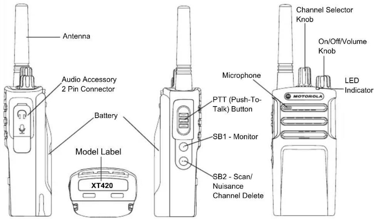
PARTS OF THE RADIO
English
On/Off/Volume Knob
Used to turn the radio ON or OFF and to adjust the radio's volume.
Channel Selector Knob
Used to switch the radio to different channels.
Accessory Connector
Used to connect compatible audio accessories.
Model Label
Indicates the model of the radio.
Microphone
Speak clearly into the microphone when sending a message.
Antenna
For model XT420 the antenna is non-removable.
LED Indicator
Used to give battery status, power-up status, radio call information and scan status.
- Press and hold down this button to talk, release it to listen.
- The Side Button 1 is a general button that can be configured by the Customer Programming Software - CPS. The SB1 default setting is 'Monitor'.
- The Side Button 2 is a general button that can be configured by the CPS. The SB2 default setting is 'Scan/Nuisance Channel Delete'.
The Lithium-Ion (Li-Ion) Battery
XT Series comes with a Standard Capacity Li-Ion battery. Other batteries may be available.
For more information, see "Battery Features
And Charging Options" on page 11.
English
This User Guide covers the XT420 Series models. The radio's model is shown on the bottom of the radio and provides the following information:
Table 1: XT420 Radio Specifications
| Model | Frequency Band | Transmit Power (Watts) | Number of Channels | Antenna |
| XT420 PMR446 0.5 16 Non-removable | | |
BATTERIES AND CHARGERS
XT Series radios provide Lithium-1on batteries that come in different capacities that defines the battery life.
BATTERY FEATURES AND CHARGING OPTIONS
About the Li-Ion Battery
The XT Series radio comes equipped with a rechargeable Li-Ion battery. This battery should be fully charged before initial use to ensure optimum capacity and performance.
Battery life is determined by several factors. Among the more critical are the regular overcharge of batteries and the average depth of discharge with each cycle. Typically, the greater the overcharge and the deeper the average discharge, the fewer cycles a battery will last. For example, a battery which is overcharged and discharged 100% several
times a day, lasts fewer cycles than a battery that receives less of an overcharge and is discharged to 50% per day. Further, a battery which receives minimal overcharging and averages only 25% discharge, lasts even longer.
Motorola batteries are designed specifically to be used with a Motorola charger and vice versa. Charging in non-Motorola equipment may lead to battery damage and void the battery warranty. The battery should be at about 77^ (25^) (room temperature), whenever possible. Charging a cold battery (below 50^ [10^] ) may result in leakage of electrolyte and ultimately in failure of the battery. Charging a hot battery (above 95^ [35^] ) results in reduced discharge capacity, affecting the performance of the radio.
Motorola rapid-rate battery chargers contain a temperature-sensing circuit to ensure that batteries are charged within the temperature limits stated above.
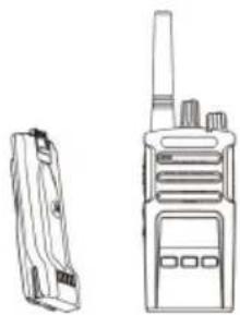
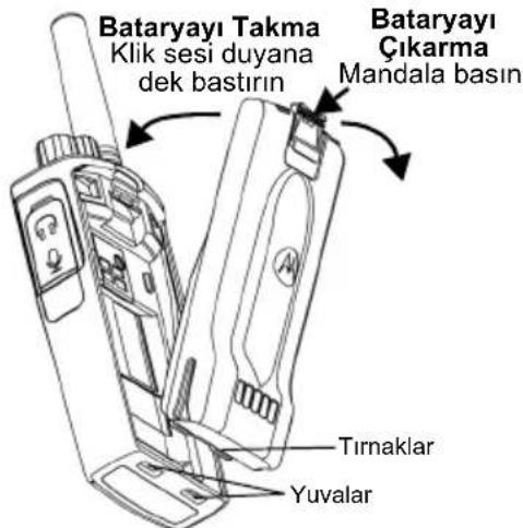
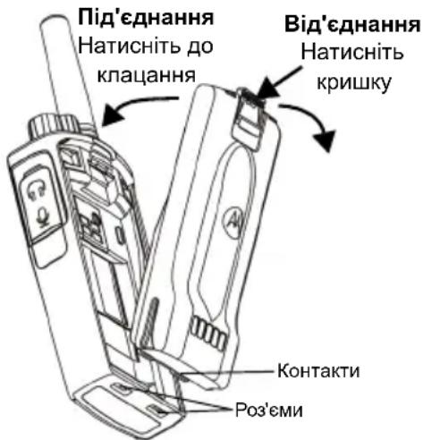
Installing the Lithium-Ion (Li-Ion) Battery
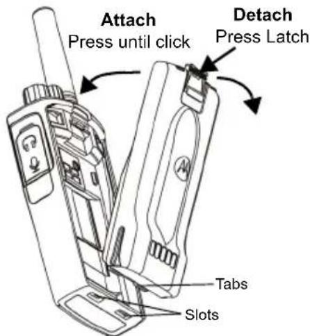
- Turn OFF the radio.
- With the Motorola logo side up on the battery pack, fit the tabs at the bottom of the battery into the slots at the bottom of the radio's body.
- Press the top part of the battery towards the radio until a click is heard.
Note: To learn about the Li-Ion Battery Life features, refer to "About the Li-Ion Battery" on page 11
Removing the Lithium-Ion (Li-Ion) Battery
- Tum OFF the radio.
- Push down the battery latch and hold it while removing the battery.
- Pull the battery away from the radio.
Table 1: Li-Ion Battery Life with Tx Power 0.5 Watts
| Battery Type | Battery Save OFF | Battery Save ON |
| Standard 16 Hours 20 Hours | |
| High Capacity N/A N/A | |
English
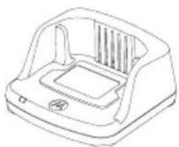
Power Supply and Drop-in Tray Charger
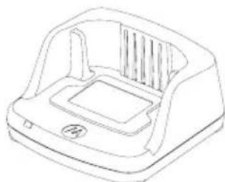
Drop-in Tray Charger
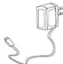
Power Supply
Your radio comes with one Drop-n Tray Charger and one Power Supply (also known as Transformer) and a set of adaptors.
Your Power Supply is capable of switching to suit any of the adaptors that comes with your radio package.
The Adaptor you install depends on the region you're located.
Once you have identified the Adaptor that matches your electrical outlet, proceed to install it as follows:
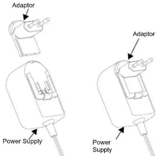
- Slide down the Adaptor grooves into the Power Supply until it snaps into place.
- Slide the Adaptor upward to remove.
Note: The adaptor shown in the pictures are for illustration purposes only. The adaptor you install may be different.
When acquiring additional Charger or Power Supply, make sure you have the similar Drop-in Tray Charger and Power Supply set.
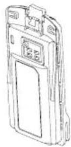
Holster
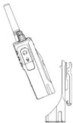
- Insert the radio into the base of the holster at an angle. Press the radio against the back of the holster until the hooks on the holster are inserted in the top recesses of the battery..
- To remove, using the top tab on the holster, detach the hooks of the holster from the top recesses of the battery. Slide the radio at an angle and remove from the holster.
Note: To charge the battery (with the radio attached), place it in a Motorola approved Charger or Multi Unit Charger.
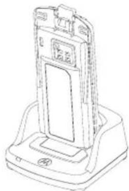
Charging with the Drop-in Tray Charger (SUC)
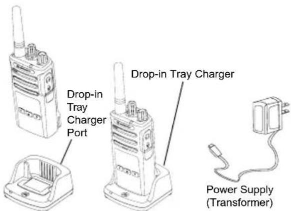
- Place the Charger on a flat surface.
- Insert the connector of the Power Supply into the port on the side of the Charger.
- Plug the AC Adaptor into a power outlet.
- Insert the radio into the Charger with the radio facing the front, as shown.
Note: When charging a battery attached to a radio, turn the radio OFF to ensure a full charge. See "Operational Safety Guidelines" on page 7 for more information.
Charging A Stand-Alone Battery
To charge only the battery - at step 4 on page 14, insert the battery into the tray, with the inside surface of the battery facing the front of the Drop-in Tray Single Unit Charger as shown above. Align the slots in the battery with the alignment ribs in the Drop-in Tray Single Unit Charger.
Table 2: Motorola Authorized Batteries
| Part Number Description |
| PMNN4434_R Standard Li-Ion Battery |
| PMNN4453_R | High Capacity Li-Ion Battery |
Drop-in Tray Charger LED Indicators
Table 3: Charger LED Indicator
| Status LED Indicator Comments |
| Power On | Green for approximately 1 second | |
| Charging | Steady Red | |
| Charging Complete | Steady Green | |
| Battery Fault (*) | Red Fast Flash | |
| Waiting to Charge (**) | Amber Slow Flash | |
| Battery Level Status | N/A Battery empty | |
| Flash Red 1 Time | Battery low |
| Flash Amber 2 Times | Battery medium |
| Flash Green 3 Times | Battery High |
() Normally, re-positioning the battery pack will correct this issue.
(^*) Battery temperature is too warm or too cold or wrong power voltage is being used.
If there is NO LED indication:
English
- Check if the radio with battery, or the battery alone, is inserted correctly. (refer to step 4 of "Charging with the Drop-in Tray Charger (SUC)" on page 14)
- Ensure that the power supply cable is securely plugged into the charger socket using an appropriate AC outlet and there is power to the outlet.
- Confirm that the battery being used with the radio is listed in Table 2 on page 15.
Estimated Charging Time
The following table provides the estimated charging time of the battery. For more information, see "Batteries and Chargers Safety Information" on page 6.
Table 4: Battery Estimated Charging Time
| Charging Solutions | Estimated Charging Time |
| Standard Battery High Capacity Battery |
| Standard ≤ 4.5 Hours N/A | | |
| Rapid ≤ 2.5 Hours N/A | | |
Charging a Radio and Battery using a Multi-Unit Charger - MUC (Optional Accessory)
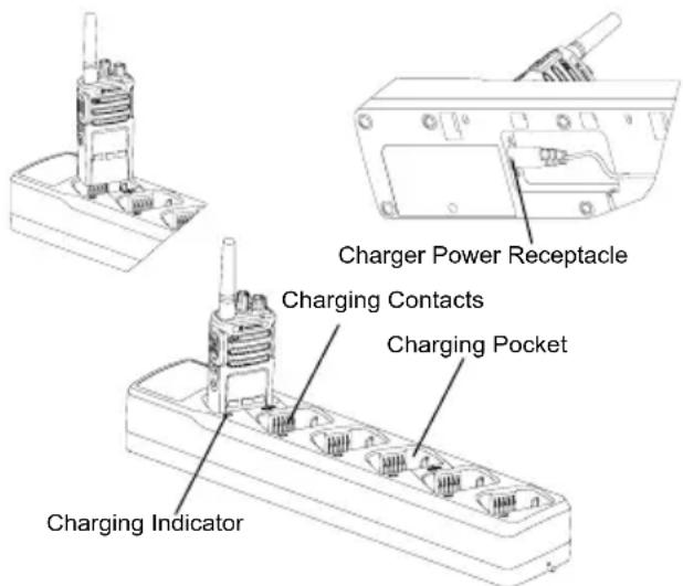
The Multi-Unit Charger (MUC) allows drop-in charging of up to 6 radios or batteries. Batteries can be charged with the radios or removed and placed in the MUC separately. Each of the 6 charging pockets can hold a radio (with or without the Holster) or battery, but not both.
English
- Place the MUC on a flat surface.
- Insert the power cord plug into the MUC's dual pin connector at the bottom of the MUC.
- Plug the power cord into an AC outlet.
- Turn the radio OFF.
- Insert the radio or battery into the charging pocket with the radio or battery facing away from the contacts.
Note:
- This MUC clones up to 2 radios (2 Source radios and 2 Target radios). Refer to "Cloning with a Multi-Unit Charger (MUC)" on page 36 for more information.
- More information on the MUC's operation is available in the Instruction Sheets provided with the MUC. For more information on the parts and their part numbers, refer to "Accessories" on page 55.
Multi-Unit Charger LED Indicators
Table 5: Charger LED Indicator
| Status LED Status Comments |
| Power On Green for approx. 1 sec | ● | |
| Charging Steady red | ● | |
| Charge Complete Steady | green | ● |
| Battery Fault (*) | Red fast flash | ● |
| Waiting to charge (**) | Amber slow flash | ● |
| Battery Level Status | Flash red 1 time | ● Battery low |
| Flash amber 2 times | ● Battery medium |
| Flash green 3 times | ● Battery high |
() Normally re-positioning the battery pack will correct this issue
(^*) Battery temperature is too warm or too cold or wrong power voltage is being used. If there is NO LED indication:
- Check if the radio with battery, or the battery alone, is inserted correctly. (refer to "Charging a Radio and Battery using a Multi-Unit Charger - MUC (Optional Accessory)" on page 18)
- Ensure that the power supply cable is securely plugged into the charger socket using an appropriate AC outlet and there is power to the outlet.
- Confirm that the battery being used with the radio is listed in Table 2 on page 15.
GETTING STARTED
For the following explanations, refer to "Parts Of The Radio" on page 8.
To turn ON the radio, rotate the On/Off/Volume Knob clockwise. The radio plays one of the following:
- Power up tone and channel number announcement, or
- Battery level and channel number announcements, or
- Silent (Audible tones disabled)
The LED blinks red briefly.
To turn the radio OFF, rotate the On/Off/Volume Knob counterclockwise until you hear a 'click' and the radio LED Indicator turns OFF.
ADJUSTING VOLUME
Turn the On/Off/Volume Knob clockwise to increase the volume, or counterclockwise to decrease the volume.
Note: Do not hold the radio too close to the ear when the volume is high or when adjusting the volume
SELECTING A CHANNEL
To select a channel, turn the Channel Selector Knob until you reach the desired channel. An audible voice indicates the selected channel.
Each channel has its own Frequency, Interference Eliminator Code and Scan Settings.
TALKING AND MONITORING
It is important to monitor for traffic before transmitting to avoid 'talking over' someone who is already transmitting
To monitor, long press and hold the SB1(*) button to access channel traffic. If no activity is present, you will hear 'static'. To release, press SB1 again. Once channel traffic has cleared, proceed with your call by pressing the PTT button. When transmitting, the LED Indicator stays solid red.
Notes:
- To listen to all activity on a current channel, short press the SB1 to set the CTCSS/DPL code to 0. This feature is called 'CTCSS/DPL Defeat (Squelch set to SILENT)'.
- (^*) This assumes SB1 is not being programmed for a different mode.
RECEIVING A CALL
- Select a channel by rotating the Channel Selector Knob until you reach the desired channel. An audible voice indicates the selected channel.
- Make sure the PTT button is released and listen for voice activity.
- The LED Indicator stays solid red when the radio is receiving a call.
- To respond, hold the radio vertically 1 to 2 inches (2.5 to 5cm) from mouth. Press the PTT button to talk; release it to listen.
Note:
- Interference Eliminator Codes are referred also as CTCSS/DPL codes or PL/DPL codes
TALK RANGE
XT Series radios have been designed to maximize performance and improve transmission range in the field. It is recommended that you do no use the radios closer than 1.5 meters apart, to avoid interference. XT460 coverage is 16.250 square meters, 13 floors and 9 KM in flat areas.
Talk range depends on the terrain. It will be affected by concrete structures, heavy foliage and by operating radios indoors or in vehicles. Optimal range occurs in flat, open areas with up to 9 kilometers of coverage. Medium range occurs when buildings and trees are in the way.
To establish a proper two-way communication, the Channel, Frequency and Interference
Eliminator Codes must be the same on both radios. This depends on the stored profile that has been pre-programmed on the radio:
- Channel: Current channel that the radio is using, depending upon radio model.
- Frequency: The frequency the radio uses to transmit/receive.
- Interference Eliminator Code: These codes help minimize interference by providing a choice of code combinations.
- Scramble Code: Codes that make the transmissions sound garbled to anyone listening who is not set to that specific code.
For details of how to set up frequencies and CTCSS/DPL codes in the channels, refer to "Entering Advanced Configuration Mode" on page 27
RADIO LED INDICATORS
| RADIO STATUS LED INDICATION |
| Channel Busy Solid Orange | |
| Cloning Mode Double Orange Heartbeats | |
| Cloning In Progress Solid Orange | |
| Fatal Error at Power up | One Green Blink, One Orange Blink, One Green Blink, then repeat for 4 seconds |
| Low Battery Orange Heartbeat | |
| Low Battery Shutdown Fast Orange Heartbeat | |
| Monitor LED is OFF | |
| Power-Up Solid Red for 2 seconds | |
| ‘Idle’ Programming Mode / Channel Mode | Green Heartbeat |
| Scan Mode Fast Red Heartbeat | |
| Transmit (Tx)/Receive (RX) Solid Red | |
| VOX/iVOX Mode Double Red Heartbeats | |
HANDS-FREE USE/VOX
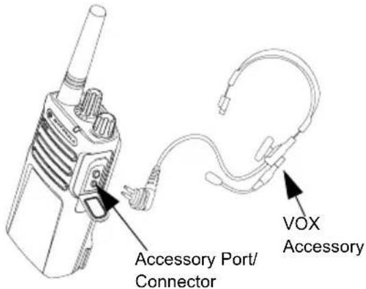
Motorola XT series radios can operate hands-free (VOX) when used with compatible VOX accessories.
With Compatible VOX Accessories
The default factory setting for VOX sensitivity level is Medium (level '2'). Before using VOX, set VOX level to a level different from '2' via the Customer Programming Software (CPS). Then, perform the following steps:
-
Turn the radio OFF.
-
Open accessory cover.
- Insert the audio accessory's plug firmly into accessory port.
- Turn radio ON. The LED Indicator will blink double red
- Lower radio volume BEFORE placing accessory near ear.
- To transmit, speak into accessory microphone and to receive, stop talking.
- VOX can be temporarily disabled by pressing the PTT button or by removing the audio accessory.
Note: To order accessories, contact your Motorola point of purchase
Setting iVOX Sensitivity
The sensitivity of the radio's accessory or microphone can be adjusted to suit different operating environments. iVOX sensitivity can be programmed via the CPS.
Default value is '3'. You can set iVOX to any value as listed below:.
- 1 = Low sensitivity
- 2 = Medium sensitivity
- 3 = High sensitivity
Hands Free without Accessories (iVOX)
- Enable iVOX by pressing the PTT Button while turning ON the radio.
- iVOX can be temporarily disabled by pressing the PTT button.
- A short press of the PTT Button re-enables iVOX.
- There is a short delay between the time when you start talking and when the radio transmits.
Microphone Gain
The sensitivity of the microphone can be adjusted to fit different users or operating environments.
This feature can be adjusted only through the CPS. Microphone default setting is set to level 2 (medium gain).
Toggle Voice Prompt in User Mode
Short press the SB1 Button while turning ON the radio to enable/disable the Voice Prompt in User Mode. (Default is set to ON).
Power Up - Tone Mode
To enable/disable power up tone mode, press SB1 and SB2 buttons simultaneously for 2-3 seconds while powering up the radio until you hear the pre-programmed power up tone. 3 different power-up tones are available.
Reset to Factory Defaults
Reset to Factory Defaults will set back all radio features to the original factory default settings. To do so, press PTT, SB2 and SB1 simultaneously while turning ON the radio until you hear a high tone chirp.
TROUBLESHOOTING
| Symptom Try This... |
| No Power | Recharge or replace the Li-1on battery.
Extreme operating temperatures may affect battery life.
Refer to “About the Li-Ion Battery” on page 11 |
| Hearing other noises or conversation on a channel | Confirm Interference Eliminator Code is set.
Frequency or Interference Eliminator Code may be in use.
Change settings: either change frequencies or codes on all radios.
Make sure radio is at the right frequency and code when transmitting.
Refer to “Talking and Monitoring” on page 20 |
| Message Scrambled | Scramble Code might be ON, and/or setting does not match the other radios' settings. |
| Audio quality not good enough | Radio settings might not be matching up correctly. Double check frequencies, codes and bandwidths to make sure they are identical in all radios |
| Limited talk range | Steel and/or concrete structures, heavy foliage, buildings or vehicles decrease range. Check for clear line of sight to improve transmission.
Wearing radio close to body such as in a pocket or on a belt decreases range.
Change location of radio. To increase range and coverage, you can reduce obstructions or increase power. UHF radios provides greater coverage in industrial and commercial buildings. Increasing power provides greater signal range and increased penetration through obstructions.
Refer to “Talking and Monitoring” on page 20 |
| Message not transmitted or received | Make sure the PTT button is completely pressed when transmitting.
Confirm that the radios have the same Channel, Frequency, Interference Eliminator Code and Scramble Code settings. Refer to “Talking and Monitoring” on page 20 for further information.
Recharge, replace and/or reposition batteries. Refer to “About the Li-Ion Battery” on page 11.
Obstructions and operating indoors, or in vehicles, may interfere. Change location. Refer to “Talking and Monitoring” on page 20.
Verify that the radio is not in Scan. Refer to “Scan” on page 32 and “Nuisance Channel Delete” on page 33. |
| Heavy static or interference | Radios are too close; they must be at least five feet apart. Radios are too far apart or obstacles are interfering with transmission. Refer to “Talking and Monitoring” on page 20. |
| Low batteries | Recharge or replace Li-1on battery. Extreme operating temperatures affect battery life. Refer to “About the Li-1on Battery” on page 11. |
| Drop-in Charger LED light does not blink | Check that the radio/battery is properly inserted and check the battery/charger contacts to ensure that they are clean and charging pin is inserted correctly. Refer to “Charging with the Drop-in Tray Charger (SUC)” on page 14, “Drop-in Tray Charger LED Indicators” on page 16 and “Installing the Lithium-1on (Li-1on) Battery” on page 12. |
| Low battery indicator is blinking although new batteries are inserted | Refer to “Installing the Lithium-1on (Li-1on) Battery” on page 12, and “About the Li-1on Battery” on page 11. |
| Cannot activate VOX | VOX feature might be set to OFF.Use the CPS to ensure that the VOX Sensitivity level is not set to ‘0’.Accessory not working or not compatible.Refer to “Hands-Free Use/VOX” on page 24. |
| Battery does not chargealthough it has been placed inthe drop-in charger for a while | Check drop-in tray charger is properly connected and correspond to acomppatible power supply.Refer to “Charging with the Drop-in Tray Charger (SUC)” on page 14 and“Charging A Stand-Alone Battery” on page 15CHECK the charger's LEDs indicators to see if the battery has a problem. Referto “Drop-in Tray Charger LED Indicators” on page 16. |
Note: Whenever a feature in the radio seems to not correspond to the default or preprogrammed values, check to see if the radio has been programmed using the CPS with a customized profile.
PROGRAMMING FEATURES
To easily program all the features in your radio, it is recommended to use the Customer Programming Software (CPS) and the programming cable.
CPS software download is available for free at www.motorolasolutions.com/XTSeries.
Advanced Configuration is a configuration mode that allows the customization of additional features via the radio's front panel.
For non-display model radios, the navigation is guided by an audible voice prompt.
When the radio is set to Advanced Configuration, you are able to read and modify three features:
Frequency Selection,
- Codes (CTCSS/DPL), and
English
The Frequencies Select feature allows you to choose frequencies from a pre-defined list.
The Interference Eliminator Code (CTCSS/DPL) helps minimize interference by providing you with a choice of code combinations that filter out static, noise, and unwanted messages.
The Auto-Scan feature allows you to set a particular channel to automatically enable Scan each time you switch to that channel.
Entering Advanced Configuration Mode
Note: Before configuring the features, make sure your radio is set to the channel you wish to program. You can do so before entering Advanced Configuration Mode or at any time during the Advanced Configuration Mode by rotating the Channel Selector Knob until you reach the desired channel.
To read or modify Frequencies, Codes and Auto-Scan, set the radio to 'Advanced Configuration Mode' by long pressing both the PTT and the SB1 button simultaneously for 3 to 5 seconds while turning ON the radio until you hear an audible voice saying "Programming Mode" and "Channel Number". The LED Indicator starts blinking a green heartbeat.
Note: 'Idle' Programming Mode is the stage in the Programming Mode where the radio waits for the user to start the radio programming cycle.
Once you are in the 'Idle' Programming Mode, you will be able to hear the Frequencies,
Codes and Auto-Scan settings by short pressing the PTT button to navigate along the different programmable features.
Entering Frequencies Values
XT Series radios use PMR446 band that has 8 frequencies available.
In 'Idle' Programming mode, the Channel number becomes the first changeable value. Select the desired channel by turning the Channel Selector Knob. An audible voice indicated the selected channel to configure. Short pressing the PTT button allows you to cycle through the other features available for configuration. Use the SB1 and SB2 button to change the values. An audible voice indicates the value selected.
Reading CTCSS / DPL Values
Cycle through the features available for configuration by short pressing the PTT button until you hear the current code. The radio moves to the programming CTCSS/PL codes mode.
Enter a new code value using the SB1 and SB2 buttons.
The XT Series radios have up to 219 codes available. For more information, refer to "Frequency and Code Charts" on page 47.
Reading Auto-Scan Values
After hearing the CTCSS/DPL codes, short pressing the PTT button moves you to AutoScan mode.
Auto-Scan has only two values:
Modify Auto-Scan values using SB1 and SB2 buttons.
Saving Settings
Once you are satisfied with the settings, you can either:
- short press the PTT button to continue programming,
- long press the PTT button to save and return to 'Idle' Programming Mode, or
- long press the PTT button twice to exit 'Idle' Programming Mode and return to the normal radio operation.
Note:
- To exit the programming mode without saving, turn OFF the radio.
- If you 'roll-over' to the beginning of 'Idle' Programming Mode, you will hear "Channel Number" and the LED Indicator blinks green again. All changed values will be automatically saved.
Programming Mode FAQ
- I got distracted while programming and forgot which feature I was programming. What should I do?
Return to 'Idle' Programming Mode and start over. You will not be able to return to Programming Mode (the radio does not provide further way to let you know the specific stage you are at in the Programming Mode).
Therefore you can:
- Long press the PTT button. The radio will return to 'Idle' Programming Mode or,
- Turn OFF the radio and enter Programming Mode again. (Refer to "Entering Advanced Configuration Mode" on page 27 for more information)
- I am trying to program a frequency (or a code) value but the radio would not do it. It rolled over and took me back to value '0'.
The radio disallows you to program any value that is not available in the frequencies and
codes pool. For example, if you try to program code 220, the radio would not accept it as the maximum value allowed is 219. Same goes for the frequencies. Refer to the "Frequency and Code Charts" on page 47 to make sure you are programming a valid value.
3. I am trying to enter the Programming Mode but the radio would not do it.
The radio may be locked using the CPS to disallow Front Panel Programming. To re-enable, use the CPS.
- I programmed the wrong value when I was programming. How can I erase or re-program the value?
If you programmed the wrong value, you can either:
-
'Roll-over' the radio. The radio 'roll-over' each time it reaches the maximum value allowed. Keep increasing (short press the SB1 button) or decreasing (short press the SB2 button) until you get the desired value or,
-
Turn OFF the radio and start over.
- I just programmed the value I wanted. How do I exit the Programming Mode?
You can either:
- long press the PTT button twice to exit if you're in the Programming Mode or,
- Long press the PTT button once if you are already in the 'Idle' Programming mode.
- I am done programming the features in this channel. How do I program another channel?
Short press the PTT button several times until you hear "Channel Number". Switch channel by rotating the Channel Selector Knob. If you wish to save the changes, make sure you are in the 'Idle' Programming Mode before switching the channel, otherwise you will lose the changes made.
PROGRAMMING VALUES EXAMPLE
Example of Programming a Frequency
Assuming current frequency value is set to Channel 1, with the PMR446 default frequency set to '02' (equivalent to 446.03125 MHz), and you want to change it to Frequency Number = '13' (which is mapped to 466.05625 MHz), follow this sequence:
- Enter Advanced Configuration Mode.
- Short press the PTT button to enter Frequency Mode. The radio audible voice announces that the current value is '2'.
- Press the SB1 button eleven times to increase frequencies and you will hear frequency "One, three" (13).
- Long press the PTT button. LED Indicator shows a green heartbeat to indicate 'Idle' Programming Mode.
- Long press the PTT button again to exit Programming Mode or turn OFF the radio.
Example of Programming a Code
Assuming the current code value is set to factory default '001', and you want to change it to CTCSS/DPL Code = 103. Follow the sequence indicated below:
- Enter Advanced Configuration Mode.
- Short press the PTT button twice. The radio audible voice announced "Code Number" (Entering CTCSS/DPL Programming Selection Mode).
- Pressing and holding SB1 or SB2 button fast forwards / rewrites the value at the nearest 10's. When released, the radio audible voice announces the first, second and third digit in full. Keep pressing the SB1 or SB2 button several times until you hear "103".
- Long press the PTT button. LED Indicator shows a green heartbeat to indicate 'Idle' Programming Mode.
- Long press the PTT button again to exit Programming Mode or turn OFF the radio.
Example of Programming Auto-Scan
Auto-Scan is the third available feature in the Programming Mode and can be set to either ON or OFF on a particular channel.
To set Auto-Scan to ON:
- Enter Advanced Configuration Mode and select the desired channel.
- Short press the PTT button three times to enter the Active Channels Programming Selection Mode. The audible voice in the radio announces "Auto-Scan" and the setting (Enabled or Disabled).
- To change the setting, press SB1 or SB2.
- Long press the PTT button. LED Indicator shows a green heartbeat to indicate 'Idle' Programming Mode.
- Long press the PTT button again to exit Programming Mode or turn OFF the radio.
OTHER PROGRAMMING FEATURES
Scan
Scan allows you to monitor other channels to detect conversations. When the radio detects a transmission, it stops scanning and goes to the active channel. This allows you to listen and talk to people in that channel without having to change channel. If there is valid channel activity on Channel 2, the radio stays on Channel 1 and you will not hear Channel 2. After the talking has stopped in Channel 1, the radio waits for 5 seconds before resuming scan again.
-
To start scanning, press the SBx (x=1 or 2) button. (Scan is defaulted on SB2 but can be programmed to either SB1 or SB2 button via CPS). When the radio detects channel activity, it stops on that channel until the activity ends. You can respond on that channel without having to switch channels by pressing the PTT button. If no transmission occurs within 5 seconds, scanning resumes.
-
To stop scanning, short press the SB1 or SB2 button (programmed for scan) again.
- If you want to scan a channel without the Interference Eliminator Codes (CTCSS/DPL), set the code settings for the channels to '0' in the CTCSS/DPL Programming Selection Mode.
Note: Whenever the radio is set to Scan, the LED Indicator blinks a Red Heartbeat.
Editing Scan List
Scan List can be edited by using the CPS. For more information refer to "Customer Programming Software (CPS)" on page 33.
Nuisance Channel Delete
Nuisance Channel Delete allows you to temporarily remove channels from the Scan List. This feature is useful when irrelevant conversations on a 'nuisance' channel ties up the radio's scanning feature.
To delete a channel from the Scan List:
- Start Scan mode by short pressing the SB1 or SB2 (programmed for scan) button.
- Wait until the radio stops receiving at the channel you wish to eliminate. Long press the SB2 button to delete it. You cannot delete the channel with scan enabled (home channel).
- The channel will not be scanned again until you exit the Scan mode by short pressing the SB1 or SB2 (programmed for scan) button again or by turning OFF the radio and back ON.
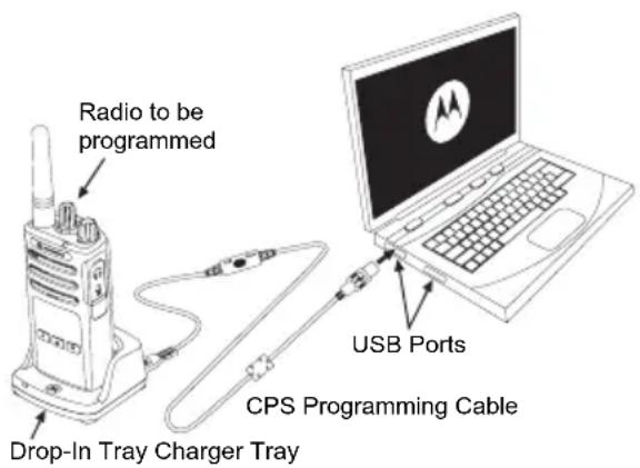
CUSTOMER PROGRAMMING SOFTWARE (CPS)
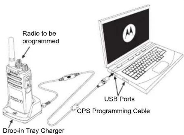
Figure 1: Setting up the radio to the CPS
The easiest way to program or change features in your radio is by using the Customer Programming Software (CPS) and the CPS Programming Cable*. CPS Software is available for free as web based downloadable software at:
www.motorolasolutions.com/XTseries
To program, connect the XT Series radio via the Drop-in Charger Tray and CPS Programming Cable as shown in Figure 1 on page 33. Toggle the cable switch of the CPS Programming Cable to 'CPS Mode'.
CPS allows you to program frequencies, PL/ DPL Codes as well as other features such as: Time-out Timer, Scan List, Call Tones, Scramble, Reverse Burst, etc. CPS is a very useful tool as it can also lock the Front-Panel Radio Programming or restrict any specific radio feature to be changed (to avoid accidentally erasing the preset radio values). It also provides security by giving the option to set up a password for profile radio's management. For more information, refer to Features Summary Chart Section at the end of the User Guide.
Note: (*) CPS Programming Cable P/N# HKKN4027_ is an accessory sold separately. Please contact your Motorola point of purchase for more information.
Time-Out Timer
This timer sets the amount of time that the radio can continuously transmit before the transmission is automatically terminated. The default setting is 60 seconds and can be changed using the CPS.
Call Tones
Call Tones feature allows you to transmit an audible tone to other radios on the same channel to alert them that you are about to talk or to alert them without speaking.
To use this feature, the Call Tones must be programmed to either SB1 or SB2 and 1 of the 3 pre-recorded tones is selected.
Scramble

The Scramble feature makes transmissions sound garbled to anyone listening without the same code. Scramble default value is OFF. To change the scramble code during radio's normal operation, the Scramble feature must be programmed to either SB1 or SB2.
Reverse Burst
Reverse Burst eliminates unwanted noise (squelch tail) during loss of carrier detection. You can select values of either 180 or 240 to be compatible with other radios. The default value is 180.
Notes:
- The features described in previous pages are just some of the features CPS has. CPS offers more capabilities. For more information refer to the HELP file in the CPS.
- Some of the features available with the CPS software may vary depending on the radio model.
CLONING RADIOS
You can clone XT Series radio profiles from one Source radio to a Target radio by using any one of these 3 methods:
- Using a Multi Unit Charger (MUC-optional accessory),
- Using two Single Unit Chargers (SUC) and a Radio-to-Radio cloning cable (optional accessory),
- the CPS (free software download)
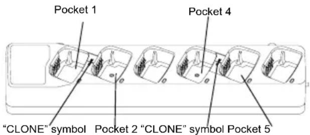
Cloning with a Multi-Unit Charger (MUC)
To clone radios using the MUC, there must be at least two radios:
- a Source radio (radio which profiles will be cloned or copied from) and
- a Target radio (the radio which profile will be cloned from the source radio.)
The Source radio has to be in Pocket 1 or 4 while the Target radio has to be in Pocket 2 or 5, matching in the MUCs pockets by pairs as follows:
1 and 2 or,
4 and 5.
When cloning, the MUC does not need to be plugged into a power source, but ALL radios require charged batteries.
- Turn ON the Target radio and place it into one of the MUC Target Pockets
-
Power the Source radio following the sequence below:
-
Long press the PTT button and SB2
simultaneously while turning the radio ON.
-
Wait for 3 seconds before releasing the buttons until the audible tone "Cloning" is heard.
-
Place the Source radio in the source pocket that pairs with the target pocket you chose in step 1. Press and release the SB1 button.
- After cloning is completed, the Source radio will announce either "successful" (cloning is successful) or "fail" (cloning has failed). If the Source radio is a display model, it will either show Pass' or Fail' on the display (a tone will be heard within 5 seconds).
- Once you have completed the cloning process, turn the radios OFF and ON to exit the 'cloning' mode.
Further details on how to clone radios are explained in the Instructions Sheet provided with the MUC.
When ordering the MUC, refer to P/N# PMLN6384_.
Notes:
- If cloning fails, refer to "What To Do If Cloning Fails" on page 40.
- Paired Target radios and Source radios must be of the same band type in order for the cloning to run successfully.
- MUC pockets numbers should be read from left to right with the Motorola logo facing front.
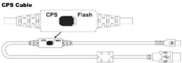
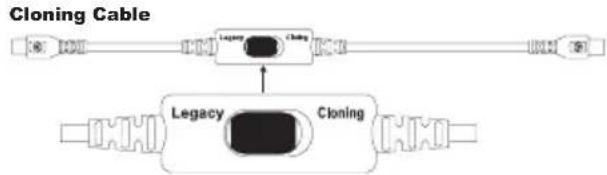
CPS and Cloning Cables (Optional Accessory)
- Both CPS and Cloning Cables are made to work either with XT Series radios or XTNi Series radios. Cloning cable supports a mix of XT and XTNi series radios.
- CPS cable programs XT series radios. Make sure the cable switch is in "Flash" or "CPS" position. To program a XTNi radio with the CPS cable, make sure the cable switch is in "CPS" position and the USB converter provided in the CPS cable kit is attached to the cable.
- Cloning cable allows you to clone:
-XT Series radios. Make sure the switch is in "Cloning" or "Legacy" position.
-XTNi Series radios. Make sure the switch is in "Legacy" position with one USB converter on each end of the cloning cable.
-XT Series and XTNi Series radios. Make sure the switch is in "Legacy" position and use a USB converter to the XTNi Single-Unit Charger. The Cloning Cable Kit provides 1 USB converter.
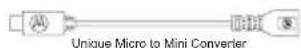
USB Converter
Cloning Radio using the Radio to Radio (R2R) Cloning Cable (Optional Accessory)
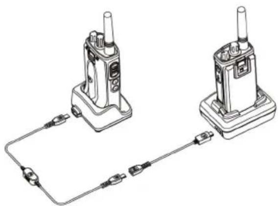
Operating Instructions
-
Before starting the cloning process, make sure you have:
-
A fully charged battery on each of the radios.
- Two Single-Unit Chargers (SUC), or 2 SUC for cloning XT Series radios, or 1 SUC for XT Series radio and 1 SUC for XTNi Series radio.
-
Turn OFF the radios and,
-
Unplug any cables (power supply or USB cables) from the SUCs.
- Plug one side of the cloning cable mini USB connector to the first SUC and the other end to the second SUC.
Note: During the cloning process, no power is being applied to the SUC. The batteries will not be charged. Only data communication is being established between the two radios.
- Turn ON the Target Radio and place it into one of the SUCs.
-
For the Source Radio, power ON the radio with the following sequence:
-
Long press the PTT button and the SB2 button simultaneously while turning the radio ON.
-
Wait 3 seconds before releasing the buttons and you hear a distinctive audible tone saying the word "Cloning".
-
Place the Source Radio in its SUC. Press and release the SB1 button.
- When the cloning is completed, the Source Radio audible voice will announce either
"successful" (cloning is successful) or "fail" (cloning process has failed). If the Source Radio is a display model radio, it will either show 'Pass' or 'Fail' on the display (a tone will be heard within 5 seconds).
- Once the cloning process is completed, turn the Radios OFF and ON again to exit "Clone" mode.
What To Do If Cloning Fails
The radio audible voice will announce "Fail" indicating that the cloning process has failed. In the event that the cloning fails, perform each of the following steps before attempting to start cloning process again:
- Ensure that the batteries on both radios are fully charged.
- Check the cloning cable connection on both SUCs.
-
Ensure that the battery is engaged properly on the radio.
-
Ensure that there is no debris in the charging tray or on the radio contacts.
- Ensure that the Target radio is turned ON.
- Ensure that the Source radio is in cloning mode.
- Ensure that the two radios are both from the same frequency band, same region and have the same transmission power.
Note: This cloning cable is designed to operate only with compatible Motorola SUC RLN6175 and PMLN6394
When ordering Cloning Cable, please refer to P/N# HKKN4028_. For more information about the accessories, refer to "Accessories" on page 55.
Cloning using the Customer Programming Software (CPS)
When cloning using this method, you need the CPS software, a Drop-In Tray Charger and the CPS Programming Cable.
To order the CPS Programming Cable, please refer to P/N# HKKN4028_.
Information on how to clone using the CPS is available either in:
- the CPS Help File -> Content and Index -> Cloning Radios, or
- in the CPS Programming Cable Accessory Leaflet.
USE AND CARE

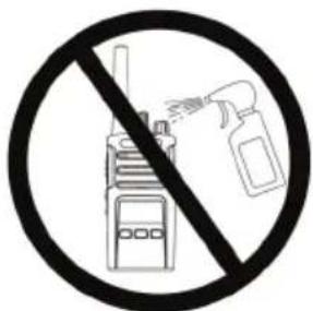
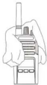
Use a soft damp cloth to clean the exterior

Do not immerse in water Do not use alcohol or cleaning solutions
If the radio is submerged in water...
Turn radio OFF and remove batteries
Dry with soft cloth Do not use radio until completely dry

English
FREQUENCY AND CODE CHARTS
The charts in this section provide Frequency and Code information. These charts are useful when using the Motorola XT Series two-way radios with other business radios. Most of the frequency positions are the same as the XTNi Series frequency positions.
Default Channel Frequency and Interference Eliminator Code
| Channel # Frequency (MHz) Code Bandwidth C |
| 1 446.00 | 625 67.0 Hz 12.5 kHz | |
| 2 446.01 | 875 67.0 Hz 12.5 kHz | |
| 3 446.03 | 125 67.0 Hz 12.5 kHz | |
| 4 446.04 | 875 67.0 Hz 12.5 kHz | |
| 5 446.05 | 625 67.0 Hz 12.5 kHz | |
| 6 446.06 | 875 67.0 Hz 12.5 kHz | |
| 7 446.08 | 125 67.0 Hz 12.5 kHz | |
| 8 446.09 | 875 67.0 Hz 12.5 kHz | |
Note: Code 754 corresponds to DPL 121
| nnel # | Frequency (MHz) | Code Bandwidth |
| 9 | 446.00625 754 12.5 kHz |
| 10 | 446.01875 754 12.5 kHz |
| 11 | 446.03125 754 12.5 kHz |
| 12 | 446.04375 754 12.5 kHz |
| 13 | 446.05625 754 12.5 kHz |
| 14 | 446.06875 754 12.5 kHz |
| 15 | 446.08125 754 12.5 kHz |
| 16 | 446.09375 754 12.5 kHz |
CTCSS AND PL/DPL CODES
CTCSS Codes
| CTCSS Hz | CTCSS Hz |
| 1 67.0 | 14 107.2 27 167.9 |
| 2 71.9 | 15 110.928 173.8 |
| 3 74.4 | 16 114.8 29 179.9 |
| 4 77.0 | 17 118.830 186.2 |
| 5 79.7 | 18 123.31 192.8 |
| 6 82.5 | 19 127.3 32 203.5 |
| 7 85.4 | 20 131.8 33 210.7 |
| 8 88.5 | 21 136.5 34 218.1 |
| 9 91.5 | 22 141.3 35 225.7 |
| 10 94.8 | 23 146.2 36 233.6 |
| 11 97.4 | 24 151.4 37 241.8 |
| 12 100.0 | 25 156.7 38 250.3 |
| 13 103.5 | 26 162.2 |
Note: (*) New CTCSS code.
PL/DPL Codes
| DPL Code DPL Code |
| 39 23 55 116 71 243 |
| 40 25 56 125 72 244 |
| 41 26 57 131 73 245 |
| 42 31 58 132 74 251 |
| 43 32 59 134 75 261 |
| 44 43 60 143 76 263 |
| 45 47 61 152 77 265 |
| 46 51 62 155 78 271 |
| 47 54 63 156 79 306 |
| 48 65 64 162 80 311 |
| 49 71 65 165 81 315 |
| 50 72 66 172 82 331 |
| 51 73 67 174 83 343 |
| 52 74 68 205 84 346 |
| 53 114 69 223 85 351 |
| 54 115 70 226 86 364 |
PL/DPL Codes (Continued)
| DPL Code | DPL Code |
| 87 365 | 104 565 121 754 | | |
| 88 371 | 105 606 123 645 | | |
| 89 411 | | 106 612 12 Customized Customized Customized Customized Customized Customized Customized Customized Customized Customized Customized Customized Customized Customized Customized Customized Customized Customized Customized Customized Customized Customized Customized Customized Customized Customized Customized Customized Customized Customized Customized Customized Customized Customized Customized Customized Customized Customized Customized Customized Customized Customized Customized Customized Customized Customized Customized Customized Customized Customized CustomIZED CustomIZED CustomIZED CustomIZED CustomIZED CustomIZED CustomIZED CustomIZED CustomIZED CustomIZED CustomIZED CustomIZED CustomIZED CustomIZED CustomIZED CustomIZED CustomIZED CustomIZED CustomIZED CustomIZED CustomIZED CustomIZED CustomIZED CustomIZED CustomIZED CustomIZED CustomIZED CustomIZED CustomIZED CustomIZED CustomIZED CustomIZED CustomIZED CustomIZED CustomIZED CustomIZED CustomIZED CustomIZED CustomIZED CustomIZED CustomIZED CustomIZED CustomIZED CustomIZED CustomIZED CustomIZED CustomIZED CustomIZED CustomIZED CustomIZED CustomIZE DPL PL 47 | |
| 90 412 | 107 624 125 Customized Customized Customized Customized Customized Customized Customized Customized Customized Customized Customized Customized Customized Customized Customized Customized Customized Customized Customized Customized Customized Customized Customized Customized Customized Customized Customized Customized Customized Customized Customized Customized Customized Customized Customized Customized Customized Customized Customized Customized Customized Customized Customized Customized Customized Customized Customized Customized Customized Custom化 DPL PL 39 | | |
| 91 413 | 108 627 126 Customized Customized Customized Customized Customized Customized Customized Customized Customized Customized Customized Customized Customized Customized Customized Customized Customized Customized Customized Customized Customized Customized Customized Customized Customized Customized Customized Customized Customized Customized Customized Customized Customized Customized Customized Customized Customized Customized Customized Customized Customized Customized Customized Customized Customized Customized Customized Customized Customized Customization DPL 40 | | |
| 92 423 | 109 631 127 Customized Customized Customized Customized Customized Customized Customized Customized Customized Customized Customized Customized Customized Customized Customized Customized Customized Customized Customized Customized Customized Customized Customized Customized Customized Customized Customized Customized Customized Customized Customized Customized Customized Customized Customized Customized Customized Customized Customized Customized Customized Customized Customized Customized Customized Customized Customized Customized Customized Customize DPL 41 | | |
| 93 431 | 110 632 128 Customized Customized Customized Customized Customized Customized Customized Customized Customized Customized Customized Customized Customized Customized Customized Customized Customized Customized Customized Customized Customized Customized Customized Customized Customized Customized Customized Customized Customized Customized Customized Customized Customized Customized Customized Customized Customized Customized Customized Customized Customized Customized Customized Customized Customized Customized Customized Customized Customized Customizd DPL 42 | | |
| 94 432 | 111 654 129 Customized Customized Customized Customized Customized Customized Customized Customized Customized Customized Customized Customized Customized Customized Customized Customized Customized Customized Customized Customizd DPL 43 | | |
| 95 445 | 112 662 130 Inverted DPL 44 | | |
| 96 464 | 113 664 131 Inverted DPL 40 | | |
| 97 465 | 114 703 132 Inverted DPL 41 | | |
| 98 466 | 115 712 133 Inverted DPL 42 | | |
| 99 503 | 116 723 134 Inverted DPL 43 | | |
| 100 506 | 117 731 135 Inverted DPL 44 | | |
| 101 516 | 118 732 136 Inverted DPL 45 | | |
| 102 532 | 119 734 137 Inverted DPL 46 | | |
| 103 546 | 120 743 138 Inverted DPL 47 | | |
English
PL/DPL Codes (Continued)
| DPL Code DPL Code |
| 139 | Inverted DPL 48 |
| 140 | Inverted DPL 49 |
| 141 | Inverted DPL 50 |
| 142 | Inverted DPL 51 |
| 143 | Inverted DPL 52 |
| 144 | Inverted DPL 53 |
| 145 | Inverted DPL 54 |
| 146 | Inverted DPL 55 |
| 147 | Inverted DPL 56 |
| 148 | Inverted DPL 57 |
| 149 | Inverted DPL 58 |
| 150 | Inverted DPL 59 |
| 151 | Inverted DPL 60 |
| 152 | Inverted DPL 61 |
| 153 | Inverted DPL 62 |
| 154 | Inverted DPL 63 |
| 155 | Inverted DPL 64 |
| ode |
| 156 | Inverted DPL 65 |
| 157 | Inverted DPL 66 |
| 158 | Inverted DPL 67 |
| 159 | Inverted DPL 68 |
| 160 | Inverted DPL 69 |
| 161 | Inverted DPL 70 |
| 162 | Inverted DPL 71 |
| 163 | Inverted DPL 72 |
| 164 | Inverted DPL 73 |
| 165 | Inverted DPL 74 |
| 166 | Inverted DPL 75 |
| 167 | Inverted DPL 76 |
| 168 | Inverted DPL 77 |
| 169 | Inverted DPL 78 |
| 170 | Inverted DPL 79 |
| 171 | Inverted DPL 80 |
| 172 | Inverted DPL 81 |
| 173 | Inverted DPL 82 |
| 174 | Inverted DPL 83 |
| 175 | Inverted DPL 84 |
| 176 | Inverted DPL 85 |
| 177 | Inverted DPL 86 |
| 178 | Inverted DPL 87 |
| 179 | Inverted DPL 88 |
| 180 | Inverted DPL 89 |
| 181 | Inverted DPL 90 |
| 182 | Inverted DPL 91 |
| 183 | Inverted DPL 92 |
| 184 | Inverted DPL 93 |
| 185 | Inverted DPL 94 |
| 186 | Inverted DPL 95 |
| 187 | Inverted DPL 96 |
| 188 | Inverted DPL 97 |
| 189 | Inverted DPL 98 |
| DPL | Code |
| 190 | Inverted DPL 99 |
| 191 | Inverted DPL 100 |
| 192 | Inverted DPL 101 |
| 193 | Inverted DPL 102 |
| 194 | Inverted DPL 103 |
| 195 | Inverted DPL 104 |
| 196 | Inverted DPL 105 206 |
| 197 | Inverted DPL 106 |
| 198 | Inverted DPL 107 208 |
| 199 | Inverted DPL 108 |
| DPL Code |
| 200 | Inverted DPL 109 |
| 201 | Inverted DPL 110 |
| 202 | Inverted DPL 111 |
| 203 | Inverted DPL 112 |
| 204 | Inverted DPL 113 |
| 205 | Inverted DPL 114 |
| ed DPL | 115 216 Customize |
| 207 | Inverted DPL 116 |
| ed DPL | 117 218 Customize |
| 209 | Inverted DPL 118 |
| DPL | Code |
| 210 | Inverted DPL 119 |
| 211 | Inverted DPL 120 |
| 212 | Inverted DPL 121 |
| 213 | Inverted DPL 123 |
| 214 | Customized DPL |
| 215 | Customized DPL |
| |
| 217 | Customized DPL |
| |
| 219 | Customized DPL |
English
MOTOROLA LIMITED WARRANTY
The authorised Motorola dealer or retailer where you purchased your Motorola two-way radio and/or original accessories will honour a warranty claim and/or provide warranty service. Please return your radio to your dealer or retailer to claim your warranty service. Do not return your radio to Motorola. To be eligible to receive warranty service, you must present your receipt of purchase or a comparable substitute proof of purchase bearing the date of purchase. The two-way radio should also clearly display the serial number. The warranty will not apply if the type or serial numbers on the product have been altered, deleted, removed or made illegible.
WHAT IS NOT COVERED BY THE WARRANTY
- Defects or damage resulting from use of the Product in other than its normal and customary manner or by not following the instructions in this user guide.
- Defects or damage from misuse, accident or neglect.
- Defects of damage from improper testing, operation, maintenance, adjustment or any alteration or modification of any kind.
- Breakage or damage to aerials unless caused directly by defects in material or workmanship.
- Products disassembled or repaired in such a manner as to adversely affect performance or prevent adequate inspection and testing to verify any warranty claim.
- Defects or damage due to moisture, liquid or spills.
- All plastic surfaces and all other externally exposed parts that are scratched or damaged due to normal use.
English
ACCESSIONS
AUDIO ACCESSORIES
| Part No. Description |
| 00115 Remote Speaker Mic BR |
| 00117 Headset w/Swivel Boom Mic |
| 00118 Earbud w/Clip PTT Mic BR |
| 00168 Lightweight headset |
BATTERY
| Part No. Description |
| PMNN4434_R Standard Li-Ion Battery |
| PMNN4453_R High Capacity Li-Ion Battery |
CABLES
| Part No. Description |
| HKKN4028_Radio to Radio Cloning Cable |
| HKKN4027_CPS Programming Cable |
CHARGERS
| Part No. Description |
| PMLN6385_ | Standard Drop-In Tray Single Unit Charger UK/EU Kit |
| PMLN6393_ | Standard Drop-In Tray Multi-Unit Charger INT UK/EU |
CARRY ACCESSORIES
| Part No. Description |
| HKLN4510_Swivel Holster |
Note: Certain accessories may or may not be available at the time of purchase. Please contact your Motorola Point of Purchase or visit www.motorolasolutions.com/XTSeries or www.motorolasolutions.com/radios/ business for latest information on accessories.
Notes
MOTOROLA, MOTO, MOTOROLA SOLUTIONS and the Stylized M logo are trademarks or registered trademarks of Motorola Trademark Holdings, LLC and are used under license. All other trademarks are the property of their respective owners.
© 2013 Motorola Solutions, Inc. All rights reserved.
Customer Programming Software (CPS) 34
www.motorolasolutions.com/XTseries
programmation client (CPS) 42
www.motorolasolutions.com/XTseries
CONSIGNES DE SECURITE POUR LES BATTERIES ET CHARGEURS
Bouton PTT (Push-to-Talk)
RéCEPTION D'UN APPEL
LOGICIEL DE PROGRAMMATION CLIENT (CPS, CUSTOMER PROGRAMMING SOFTWARE)
www.motorolasolutions.com/XTseries
Codes PL/DPL (suite)
Codes PL/DPL (suite)
| DPL Code | DPL Code |
| 139 | DPL inversé 48 |
| 140 | DPL inversé 49 |
| 141 | DPL inversé 50 |
| 142 | DPL inversé 51 |
| 143 | DPL inversé 52 |
| 144 | DPL inversé 53 |
| 145 | DPL inversé 54 |
| 146 | DPL inversé 55 |
| 147 | DPL inversé 56 |
| 148 | DPL inversé 57 |
| 149 | DPL inversé 58 |
| 150 | DPL inversé 59 |
| 151 | DPL inversé 60 |
| 152 | DPL inversé 61 |
| 153 | DPL inversé 62 |
| 154 | DPL inversé 63 |
| 155 | DPL inversé 64 |
| ode |
| 156 | DPL inversé 65 |
| 157 | DPL inversé 66 |
| 158 | DPL inversé 67 |
| 159 | DPL inversé 68 |
| 160 | DPL inversé 69 |
| 161 | DPL inversé 70 |
| 162 | DPL inversé 71 |
| 163 | DPL inversé 72 |
| 164 | DPL inversé 73 |
| 165 | DPL inversé 74 |
| 166 | DPL inversé 75 |
| 167 | DPL inversé 76 |
| 168 | DPL inversé 77 |
| 169 | DPL inversé 78 |
| 170 | DPL inversé 79 |
| 171 | DPL inversé 80 |
| 172 | DPL inversé 81 |
| 173 | DPL inversé 82 |
| 174 | DPL inversé 83 |
| 175 | DPL inversé 84 |
| 176 | DPL inversé 85 |
| 177 | DPL inversé 86 |
| 178 | DPL inversé 87 |
| 179 | DPL inversé 88 |
| 180 | DPL inversé 89 |
| 181 | DPL inversé 90 |
| 182 | DPL inversé 91 |
| 183 | DPL inversé 92 |
| 184 | DPL inversé 93 |
| 185 | DPL inversé 94 |
| 186 | DPL inversé 95 |
| 187 | DPL inversé 96 |
| 188 | DPL inversé 97 |
| 189 | DPL inversé 98 |
Codes PL/DPL (suite)
| DPL | Code |
| 190 | DPL inversé 99 |
| 191 | DPL inversé 100 |
| 192 | DPL inversé 101 |
| 193 | DPL inversé 102 |
| 194 | DPL inversé 103 |
| 195 | DPL inversé 104 |
| 196 | DPL inversé 105 206 |
| 197 | DPL inversé 106 |
| 198 | DPL inversé 107 208 |
| 199 | DPL inversé 108 |
ACCESSIONS DE TRANSPORT
www.motorolasolutions.com/XTseries
www.motorolasolutions.com/XTSeries.
MODO ADVANCED CONFIGURATION (CONFIGURACION AVANZADA)
www.motorolasolutions.com/XTseries
HKLN4510_Funda giratoria
CPS (Customer Programming Software) 36
Timer di timeout 37
Toni di chiamata 37
Codifica 38
Burst inverso 38
(Customer Programming Software) 44
www.motorolasolutions.com/XTseries
pulsante PTT (Push-to-Talk)
www.motorolasolutions.com/XTSeries.
CPS (CUSTOMER PROGRAMMING SOFTWARE)
www.motorolasolutions.com/XTseries
| N. canale | Frequenza (MHz) | Codice | Larghezza di banda |
| 1 | 446,00625 | 67,0 Hz | 12,5 kHz |
| 2 | 446,01875 | 67,0 Hz | 12,5 kHz |
| 3 | 446,03125 | 67,0 Hz | 12,5 kHz |
| 4 | 446,04375 | 67,0 Hz | 12,5 kHz |
| 5 | 446,05625 | 67,0 Hz | 12,5 kHz |
| 6 | 446,06875 | 67,0 Hz | 12,5 kHz |
| 7 | 446,08125 | 67,0 Hz | 12,5 kHz |
| 8 | 446,09375 | 67,0 Hz | 12,5 kHz |
© 2013 Motorola Solutions, Inc.
Avisos legais do software Open Source:
www.motorolasolutions.com/XTseries
www.motorolasolutions.com/XTseries
© 2013 Motorola Solutions, Inc.
Customer Programming Software
(CPS - Klantprogrammeringssoftware) 34
Time-Out Timer 35
Oproeptonen 35
Scramble 35
ReverseBurst 35
Push-to-Talk-knop (PTT)
www.motorolasolutions.com/XTseries
CPS (Customer Programming Software) 33
Timer for timeout 34
Opkaldstoner 34
Kryptering 34
ReverseBurst 35
JUSTERING AF LYDSTYRKEN
Drej taend-/sluk-/lydstyrkeknappen med uret for at skrue op for lyden og mod uret for at skrue ned for lyden.
www.motorolasolutions.com/XTseries
HVAD ER IKKE DAEKKET AF GARANTIEN
© 2013 Motorola Solutions, Inc.
Customer Programming Software (CPS) 33
Timeout-tidsgrans 34
Anropssignaler. 34
Kryptering 34
Omvand burst 35
Klona en radio 36
UPPHOVSRÄTT FÖR DATORPROGRAMVARA
www.motorolasolutions.com/XTseries
Push-to-Talk-knapp (PTT)
www.motorolasolutions.com/XTseries
Forattprogrammeraansluterdur radionixT-serienvia laddaren medfackoch CPS-programmeringskabelnsasomvisaisBild1paskidan33.Stallin kabelvaxelnpCaPS-programmeringskabelnp"CPSMode".
© 2013 Motorola Solutions, Inc.
Med ensamratt.
(Microphone Gain) 25
www.motorolasolutions.com/XTseries
© 2013 Motorola Solutions, Inc.
Nuisance Channel Delete (Slett brysom kanal) 33
Customer Programming Software (CPS) . . . 34
Tidtaker for tidsavbrudd 35
Ringetoner 35
Kryptering 35
Stoyssperre 35
Klone radioer 36
Kloning med en lader for flere enheter (MUC) 36
PRODUKTSIKKERHET OG RF EKSPONERINGSSAMSVAR

För du tar i bruk dette**
produktet, på du lese
bruksanvisningen og
informasjonen om RF-energi,
som du finner i heftet om
produkt sikkerhet og RF-
eksponering som fulgte med
radioen.
OBS!
www.motorolasolutions.com/XTseries
PTT-knapp (Push-to-Talk, trykk for à snakeke)
Nuisance Channel Delete (Slett brysom kanal)
Med Nuisance Channel Delete (Slett brysom kanal) kan du midlertidig fjerne kanaler fra skannelisten. Denne funksjonen er nyttig när irrelevante smtaler på en 'brysom' kanal legger beslag på radioens skanningsfunksjon.
www.motorolasolutions.com/XTseries
© 2013 Motorola Solutions, Inc.
Med enerett.
Lityum-Iyon (Li-Ion) Batarya .9
Bataryalar ve Sarj Cihazlari 11
Lityum-Iyon (Li-Iyon) Bataryayi Takma...12
Lityum-lyon (Li-Ion) Bataryayi
Çikarma 12
www.motorolasolutions.com/XTseries
BATARYA VE ŞARJ CIHAZI GÜVENLIK BILGILERI
Lityum-lyon (Li-Ion) Batarya
Lityum-lyon (Li-lyon) Bataryayi Takma
Lityum-Iyon (Li-Ion) Bataryayi Cikarma
- Telsizi KAPATIN.
- Bataryayi qikarirken batarya mandalini bastirarak asagidogru itin.
- Bataryayi telsizden cikarin.
www.motorolasolutions.com/XTseries
| 173 | Ters Çevrilm)iş DPL 82 |
| 174 | Ters Çevrilm)iş DPL 83 |
| 175 | Ters Çevrilm)iş DPL 84 |
| 176 | Ters Çevrilm)iş DPL 85 |
| 177 | Ters Çevrilm)iş DPL 86 |
| 178 | Ters Çevrilm)iş DPL 87 |
| 179 | Ters Çevrilm)iş DPL 88 |
| 180 | Ters Çevrilm)iş DPL 89 |
| 181 | Ters Çevrilm)iş DPL 90 |
| 182 | Ters Çevrilm)iş DPL 91 |
| 183 | Ters Çevrilm)iş DPL 92 |
| 184 | Ters Çevrilm)iş DPL 93 |
| 185 | Ters Çevrilm)iş DPL 94 |
| 186 | Ters Çevrilm)iş DPL 95 |
| 187 | Ters Çevrilm)iş DPL 96 |
| 188 | Ters Çevrilm)iş DPL 97 |
| 189 | Ters Çevrilm)iş DPL 98 |
PL/DPL Kodlari (Devami)
© 2013 Motorola Solutions, Inc.
www.motorolasolutions.com/XTseries
Przycisk Push-to-Talk (PTT)
www.motorolasolutions.com/XTSeries.
TRYB KONFIGURACJI ZAAWANSOWANEJ
www.motorolasolutions.com/XTseries
© 2013 Motorola Solutions, Inc.
Pyka Bn6opy KaHaJIb 9
Po3'Em dIa akcecyapib. 9
HakneKa 3 Ha3BOIO MoJei .9
Mikpooh. 9
AHTeHa 9
CbitnoioHn iHdkaTOp. 9
BiHNI KhoNKn 9
Jitii-ioHHn (Li-Ion) akymyIaTOp . . . . .9
AkymyaTOpTa 3apndhi npncTroi . . .11
XapakTepeNCTnKn akymyIaTOpIB ta cnocobn
3apxkanna 11
JIiTiI-oIHnI aKymyJrToPn 11
BcTaHOBJIeHHN iTii-iOHHoro (Li-Ion)
akymyITopa 12
BnMaHHa NiiH-iOHHoro (Li-Ion)
akymyITopa 13
JNTKOM DnB BCTaBnaHn npuNay. 13
Ko6ypa. 14
3apxkannha 3a DOnOMOIO 3apHOrO
npioctpoHa oDInn npuJa i3 NOTKOM
Bn6ip paiokaHany. 21
YkpaIHcbka
MIn IOBIDOMJIeHnMa Ta MOHiTopnHr .21
Ppniom BnKNIky 22
ДаьнICTь ВИКПИКу 23
CbitIOiDiHi iHnKaTop np paioctaui . . .24
BiHOBnEHnCTaHdapTHnx
HanaWtYBaHb .27
IporpamOBaHi yHKuii.28
«Advanced Configuration Mode»
(PeXIM po3uHpeHnx MOxInBOcTei
HaanaTsyBaHHn. 28
PepexiD opekmy
«Advanced Configuration Mode»
(Pexm po3upeHx MOKINBOCTe
HaJauTsyBaHHra) 29
BBeHnHaueHb yactOT 30
Ipebeipka 3NaueHb KoIDB
CTCSS/DPL. 30
IpeBipka 3HaueHb
ABTOCKaHyBaHH 30
36epekeHHaHaauTyBaHb. 31
Ppiklaand nporpaMyBaHHa3HaueHb 33
PnKnaI npOrpaMyBaHHaCTOTn 33
PnKnaI nporpaMyBaHHa KoNy 34
PnKnaI nporpaMyBaHHa
abTOCKaHyBaHH 34
IHHpi nporpamOBaHI yHKcii 35
CkaHyBaHH 35
PedaryBaHHn nepeniky cKaHyBaHHn 36
BudaneHH He6kaHx KaHaiB 37
Komn'tephe nporpamHe 3a6e3neueHHa
IINDbiDyanbHoro nporpamyBaHHA
(CPS) 37
Taimepo6mexeHHaucypepaui 38
ToHaJIbHI BnKNIKK 38
CkpeM6JIIOBaHHra 39
npncpoHa KJIbKa npnlaib .40
Ka6eni dny I3 CPS Ta KnohyBaHHa
KoI CTCSS Ta PL/DPL. .54
06mexeHa rapaHTiKaMnahii
Motorola 59
Akkecyapn 61
AydioaKcecyapu 61
AkymyIyTop 61
Ka6eni 61
3apnipocpoi 62
Akccecyapn dIy HocIHn npncTpoIO 62
ABTOPCbKI IINPABA HA KOMN'OTEPHE IPOrPAMHE 3A6E3NEUeHHa
До ckладу п dedставлих у данomy посику npoduktв komпаи Motorola moxyь BXODHTN komn'tephi nporpamn, zu 36epiraTbcry y HanibnpobidHnKOBi nam'ayi abo ha iHux Hociax. 3akOHoAbCTBOM CUSA Ta iHux kpaIH nepeid6aueHi neBHi BnKlOuHi npaba Kompani Motorola Ha 3axIeHi ABTOPbKm npabOM komn'tephi nporpamn, BKIOUaOHy, nomix iHoro, BnKJIOnyHe npaboHa koniIOBaHHa 60 BiIDTBOpEHnY bdy-b-kyn cnoci6 3axIeHHx ABTopcbKm npabOM komn'tepHHx nporpam. 3BaxaOnuHa ue, 3abOpOHcTbcS y bdy-kynn cnoci6 KoniIOBaTH, BiIDTBOpOBaTH, 3miHOBAtN, 3diCHIOBaTH 3BOPOThe npoeKTyBaHHa 60 pO3NOBCIQdKyBaTH 6yd-b-kyi 3axIeHi abTopcbKmM npabAMn Komn'tepHI nporpamn Kompani Motorola, zu BxoJaTb do cknady
YkpaIHcbka
OncybaHx y cboMy noci6nky npodyktib Kompani Motorola, 6e3 nonepedhboi Ncmbooi 3roN KOMpani Motorola. Okim TOrO, npud6aHHn npodykui KOMpani Motorola kOdHm YHOM He e npramm a6o Hnpamn HaandaHHm 6yd-koI liueH3ii Ha o6'ekTn ABTOpcbKOrO npaba, nateHTIB a60 3aBn Ha OTPMaHHn NaTeHTIB KOMpani Motorola, nn To Ha niCTabi No36abLeHHn npaba 3anepeyuBaHH, nn To 3 iHUnx npuHn OKpim 3BnuaHoi HeBNUIOUHOI liueH3ii Ha BVKOpNCtAHH, rka 3a 3aKOHm HadaeTbcr npn npodaJy npodykTu.
BIDOMOCTI UOIOBE3NEKN
BIDIOBIDHICTb IPODyKTy BIMOTAM 0ODo BE3NEKN TA PAIOUCACTOTHOTo BINPOMIHBOAHNIA

Ipeed BnKOpNCtAHNm cboBnpo6y npouHTaTe cei nocibnK i3 ekcnnyatauii Ta 03HaioMTecs 3 BiIOMOCTaMn 1oO pIBHpaioactOTHO BnnpomHHBaHH, HabeHMMn B 6pOwpyi 巴 e3菲 H H C T b Bnpo6y Ta pIBHi paioactOTHO BnnpomHBOAHNRA), 10 BXODITb DO KOMJIeKTy paioipncTPOU.
YBAGA!
BidnoiDIO BnMOr FeepaIbHOI KOMicii 3i 3B'3ky (CUSA) 0do pIBHIB paioactoTHoro BnnpomHHBaHHa CE npncpi INpnaHaueHn BnKluOHO IIN PPOpeciHOROBKOpNCtAHN.
IpepiKaHTeH,akymyJITopiBa iHux akcecyapib,CXBaJIeHx KOMnaiHcO Motorola, nIB.Ha Be6-caTi:
www.motorolasolutions.com/XTseries
IHΦOPMALI3 TEXHIKNE3NEKN PNI POBOTI 3AKUMYJATOPAMNA3APNHNMI PPNCPOA
LcienokymeHTmictntbBaxnBi iHctpykui
Ioo 6e3neKn ta ekcnnyatauii. YBaXHo
npouHTaTe ci iHcTpykui Ta 36epexitb ix dna
noaIbwo BKNOpncTaHH.
Ipeed noaTkom BnKOpncTaHH 3apdHOro npictpoI dIy akyMnyTopa O3HaNoMTec3 ycima IHCTpyKciIMu Ta INonepeJxByBaJIbHIMN IO3Nauchkamn Ha
3aapyHOMy npicStpoi,
- akymyITopiTa
Ha paioctanii, 10 npauoe BiD akymyrtopa
-
3MeHHTn p3NK ykoJKeHB, BkOpncTOByTe TInbKn aKymJrTopn, CxBaJIeHi KOMnHaIcIO Motorola. IHIa akymJrTopn e B6yXoHe6e3neuHmTu MoKyTb CnpNCHNT npABMn Ta MaTePiJIbHi 36ntKn.
-
BnKOpNCaHHaKcEcCyapiB, He peKoMeHDoBaHnx KomnaHieO Motorola, MoKe npu3BeCTn Do 3aMaHHa, ypaKeHHa eJeKTpUHm CTpyMOM a6o TpaBMyBaHHa.
- Ⅲo6 yHnKHyTn yWkoJxHeHHe neKtpuHoi BnKn Ta DpoTy, npN BiKNoUeHHi 3apAHorO npncToIO BiD po3eTK TgHiTb 3a BnKy, a He 3a dpit.
- BnKOpNCaHnNoIOBxUyBaHa Do3BOJIeTbcra Inue y pa3i KpaHbOoi Heo6XiHocTi. BnKOpNCaHnNoIOBxUyBaHa, 00 He BiDnOBiJaB CnMOram, MoKe CTaTI npuHHO 3aMaHHa a6o ypaXeHHN eJeKTPuHm CTpyMOM. RaO BnKOpNCaHnNoIOBxUyBaHa e Heo6XiHm, nepeKoHaIteCra, 00 BnKOpNCTOByETbcra Dpi KIacy 18 AWG 3a DoBxHn Do 30,48 M (100 cyTIB), Ta 16 AWG 3a DoBxHn Do 45,72 M (150 cyTIB).
-
3mehnnt np3nk 3aImaHH, ypaKeHH eJektpnHIM CTPyMOM a6o TpaBMyBaHH, He BnKOpNCTOByTe HecnpabHb i a6o ykoDkeHi 3apdHi npncTpoi. IpepaIte ix do cepTnphiKOBaHorO npeIcTaBHNtBA KOMNaHII Motorola i3 cepbichoro o6cnyrobyaHH.
-
He po3bpaIte 3apdHn npucTpi; BiH He nidrae peMOHTy Ta 3amHi HecnpaBHX qactn. Po3bpaHHa 3apdHoro npucTpoIO noB'3aHe i3 p3NKOM ypaKeHH eJeKTPuHm ctpymom Ta 3aMaHHa.
- 3meHHTn p3nk ypaXeHH eEeKtpnHm ctpymom, neped npoBeHnM 6ydb-axn onepaui 3 texHiHOrO o6cIyroBvBaHH a60 ouHHeHH BIDKnUoyaTe 3apAHy npncTpi Bid po3ETKN 3miHoro ctpymy.
IHCTPYKJIa 3 B3NEUHOI EKCJIYATAUII
-Пд уас заряжання akymулгета ВIMикайт蔡dionpuctri.
3apdHn npucpi He npnaueHn dny BnKOpncTahn npocTo He6a.BnKOpncTOBynte Noro liuhe BCyHX npmiueHHx/YMObax.
-Пдкночаite 3apdHn npicTp i JIWe do
ДрOTOBx DkepeJ KINBLeHn,Ha JkIX HaJIeKHM
YHOM BCTaHOBNeHo PJIaBki 3anO6iKHNi, i3
BIDIOBIDHM pIBHem HAnpyrN (ЯКВka3aHo Ha
npoDykti).
Дя BiДКЛЮЧЕНЯ 3apAДHOrO npIcTpoH BiDМерекhoi HanpyrN BHTaRHiTb roJIOBnPo3'Em 3po3ETKn.
- Po3eTka, Doякоi πιДКЛIOUaεΤbCS ζe o6JIaIHaHHa, Maε 3HaxOДИТИСА NOPYU, y JERKOДОCTYINHOMy Micci.
Ko do CKnady 6naHaHHBxOJaTb nnabki 3anobixHKn, nIac ix 3amHn CnIDkyte 3a TmM, 06 TnT a KIAC HOBX 3anobixHKiB BiNobidaHn BUMoram IHCTpyKuiJ do 6naHaHH.
MaKcHMaJIbHa TeMnepaTpyo OTOuyUOHO cepeIOBnIa JxKepeIa KINBHeHH He IOBnHnA nepeBnUyBaTu 40^ (104^)
PibehBuxiHoiInotyXHocTiJxKepeNa XINBHeHHn HeNoBHeHnepeBnUyBaTu3HaueHb,BkA3aHnx HaHaKJIeui 3Hn3y Ha 3apdHomy npicTpOIO.
ДрIT NOBINHEN 6yTN pO3TaIOWBaHn B TAKOMY MICTI, De BKNIOUaEbCra NOrO KOHTaKT i3 BOIOO, ySkoJKeHHa6o TnCK, Ta De Ha Hboro HEMOXJIINO HAcTyNtN a6o NepeCheNtncs Ypee3 HbOro.
3AΓΑΙΝΗΝΟΓλΕρ RAДIOCTAHцI
BiuHa KhoNka 2 (SB2)
BiyHa KhoNka 2E KhoNkoI 3aRaJIbHoro npn3HaueHHra Ka HanaTObyETbcra 3a donomoroIO I3 CPS.HanaWtYBaHHraIg KhoNk SB2 3a 3amOBuBaHHm - «CkaHyBaHH/ BuaJaleHH He6aKaHnx KaHaIIB
Iitii-ionHn (Li-Ion) akymyntop
Papioctaunii cepii XT noctaaybcey kOMnneKti i3 niTi-iOHHmN aKymyIaTOpAMnCTaHdaptHOi EMHOCTi. MoxJIbBe BnKOpNCaHHnIHux TnIB aKymyIaTOPiB. Di3HaTncs6iNbweMOxHa y «XapaKTepnCTnKn aKymyIaTOPiBaTcNoCo6n 3apJxKaHHra» Ha cTOp. 11.
Y cybomy noci6nky KopncTyBaHa onncaHO dekiIbka moDenei cepii XT420. Ha3Ba moDeni Ta II TexHiXapaKTePncTnKn Bka3aHi B HnXHiJ qacTHHi paioctaHci:
Ta6nca 1: XapaKTepeNCTnKn paIioctaHci XT420
AKUMYJIATOPN TA 3APJHII PNUCTPOI
Papionpina cepii XT o6naHaHi JitienioHHmna akymyTopampi3HOI cMHOCTi Ta, BiIOBIDHO, p3HOro pecypcy.
XAPAKTEPNCIKN AKUMYJATOIB TA CPIOB3APJxAHH
Jitii-ionhi akymyIaTOPn
paioctaunii cepii XT noctaayotbcB KOMnIeKti i3 nii-iOHnIMn akymyIaTOpAMN. Ira 3a6e3neueHHMaKcImaJIbHOI cMHOCTi Ta ONtImaJIbHnx ekCnIpyatauHnx XapaKTepnCTNK nepeod nowaKom ekCnIpyatauii akymyIaTOp cIid NOBHicTIO 3apAHTNI.
Pecypc akymyIaTopa Bn3HaacTbc7eKlBkOMa
ΦakTopamn. Hain6iNbIuKIDINBUMn
ΦakTopamn E peryIaRHe HADNIuKOBe
3apJxAHNHa kMyJIaTOpIB Ta IIN6OKe
p03paJxKeHHB KOKHOMy UIKJI. 3a3Bvua, YIM
6IbHn HaDNIuKOBn 3aprOtpmUe npInaIad
Ta YIM TIN6We BiH po3pJdxJaTbcS, TUM MeHwe ZIKNIB 3apJdxKeHHa-p03pJdxKeHHa BHTPImae akymyIATop. HanpIKnIaI, akymyIATop, 1o OTPMYe HADNIuKOBn 3apJd Ta NOBHiCTIO PO3pJdxJaTbcS DeKJIbKa pa3iB Ha DeHb, BVTPImaE MeHwe ZIKNIB, HIX akymyIATop, kIn pIDwe nepe3apJdxJaTbcS Ta 0OJeHHo PO3pJdxJaTbcS Ha 50%. OkpIM TORo, H6aRaTO DOBWe CJIyKNTMe aKymyIATop, kIn MaJxHe OTRPMYe HADNIuKOBoro 3apJdy Ta B CepeHNbOMy PO3pJdxJaTbcS He 6JIbWe HIX Ha 25%.
AkyuITopn Motorola po3po6JIeHi
cneuaIbHO dIy BnKOpNCTaHHy y KOMJIeKTI i3
3apJHIMn npIaIamn KOMNaHII Motorola, kki,
y CBOU chepy, npI3HaueHi came dnn
3apJxHaHHraKx akymJrTopiB.
BnKOpNCTaHHra 3apJxHaHHra npIaIbIB
IHuxn BnpObHNIkMoKe npI3BeCTn Do
noIkoJXeHHn AkyMylAToPIB Ta cKacYBaHHra
rapaHTII Ha aKymJrTop. ONTImaJIbHOIO
TempepatyoEKCnIyatauii akymJrTopo E
kimatha Tempepatya, to6To 25^ (77^) 3apJxHaHHn OxIoNDxeHOro akymJrTopa (Hnxue 10^ [50^] ) MoKe CTaTI npIcuHNO
BtOKy eJeKTpOliTy, a y DeKnx BnPaAdkax
HabITb BnXOdy aKymJrTopa 3 IaHy.
3apJxHaHHn neperPiTO rOaKymJrTopa (noHaD 35^ [95^] ) npI3BoIDNbDo 3HnxeHHry Ioro
EMHOCTi, HeRaTINBHO BnINBAIOHn Ha
ekcnPyatauiHi xapaTeepntKn paiaocTaHii.
IJa 3abe3neueHHra ONTImaJIbHx yMOB
3apJxHaHHn aKymJrTopiB BiIDNoBIdHO do
3a3HaueHHx BnIe TempeatypHnx yMOB
npICTPOI dIy SwNdkoro 3apJxHaHHra
BnPo6HnTuBA KomnaHII Motorola ochaSeHi
DaTChkAmn Tempepatypri.
BcTaHOBHeHHa NiTiH-oHOrO (Li-Ion) akymyIaTopa
- BUMKHITb paiaionpncptpi.
- Po3TaWyIe akMyJrTOpHn BiDcIK IOROTINOM Motorola dOrOpN Ta 3ictaBTe KOHTaKTN B HIXHI chactnHi akMyJrTopa i3 KOHTaKTAMN BH3y Ha Kopnyci paioctaHii.
- Починочни 3 Верхього Краю,do Кацання npintncihItb akymулготорdo paioctanii.
Ipnmitka. OshaHOMITnca i3 DOknaDHiOHO iHOpMaueIO uOo pecypcu IiT-iOHHX akymyIaTOPiB MOxHa y po3diNl «JIiTioHHI akymyIaTOPn» Ha cTOp. 11.
BnMaHna NiTiN-IOHOrO (Li-Ion) akymyIaTopa
- BVMKHITb paiaionpncstpi.
- 3cyhble KpnuKy akymyjTopa Bn3 Ta, TpImaHOn II npNTncHyToIO,
- BITrHiB akymyIaTOp i3 paioctaHuii.
Ta6nua 1: Pecypc nii-iOHHoro akymyIaTopa notyxHicTHo 0,5 BaTT dpaiaocTaNiiB cepii TX
| Тип
akумлаятора | Реким
ekономii
Зapаду
ВИМК. | Реким
ekономii
Зapаду
УВIMK. |
| Стондану | 16 говин | 20 говин |
| Підвицени
емностi | H/D H/D | |
Po3paxyHkoBn Yac 3apJxKaHHa
Y Ta6nci HabeDeHO po3paXyHKOBn yac 3apxJxHnAkyMylTopa. Ii3HaTncs 6JIbSe MoXHa y «IhOpMaicj 3 TexHikn 6e3neKn npu pOboti 3 akymyJrTOpAmn Ta 3apxHmN npucTPOAMn» Ha cTOp.6.
Ta6nua 4: P03paxyHkoBn Yac 3apJdxKaHHaKymyIaTopa
BidHOBHeHH CtaHdapTHnx HanaTuBaHb
Ipebeipka 3NaueHb KoIDB CTCSS / DPL
KopoTkoHaTnCKaIOu TAnReHTyPTT,
pepexoDbTe BiD OndHieI nporpaMoBaHOi 0yHKci
do iHooi,doKN He noCyte NoTpbi6Hni KOD.
Paionpncpi nepeJeDo pexmMy
nporpaMyBaHHaKOdIB CTCSS/PL.
KopncTyOuNcB KHONkAmn SB1 Ta SB2, BBeiTb HOBe 3HaueHnKaOy.
B paionpncpox cepii XT moxha BnKOpNCToBvBaTn do 219 KoDiB. DokpaHiwe npo ue nB.y «Ta6nici YactOT Ta KoDiB» Ha cTop.53.
IpeBipka 3HaueHb aBTOckaHyBaHHa
NoyBn 3NaueHHKoJiB CTCSS/DPL, KOpOTko HATNCiTb TaHReHTy PTT,06 nepeiTn Do pexmMy aBTOckaHybaHH.
PexnM aBTOckaHyBaHHMae IINue DbA cTaHn:
3MiHeHHaHaueHb aBTOckaHyBaHHaBi6yBaTbcra 3a DOnOMoIO KHOJOK SB1Ta SB2.
36epekeHHHaJaawTyBaHb
O6paBm 6aXaHi 3HaueHH, BnKoHaIte OdHy 3 O3HaueHnx Di:
KopoTko HaTnChiItb TaHreHTy PTT Ta npoDobkTe nporpaMyBaHHa,
HaTnCHyBm Ta yTpmyuOu T aHreHTy PTT, 36epexitb HanaaTyBaHHry NOBepHITbcrdopeKIMy《OuyBaHHra nporpaMyBaHHra6o
- HATINCHYBUN Ta yTpIMyOuHTaTHReHr TY PTT Dbiyi, BnDITb 3 peKIMy «OuyiKaYBaHHra» nporpaMyBaHHa Ta noBepHiTbcA DO HopMaIbHoRo peKIMy po6oTu paiaocTaHci.
PnmiTka.
- Ⅲo6 BnItn 3 pexmMy nporpaMyBaHHa 6e3 36epexeHHa 3MiHeHb, BUMKHITb paionpncpi.
-ЯкwoBn noBepHnyinscb do nooatky peKmMy «OuykBaHHra» nporpaMyBaHHra, npoiwoBwn Bci oni, Bu nooyte nobidomJeHHra «Channel Number» («HomepKaHaNoy») ncbiTnoioDnHi iHdkatop 3HOB 6JImaTIme 3eJeHm. Bce 3miHeHi 3NaueHHra 6yde aBTOMaTUnHo 36peKeHo.
3anumannu u biDnoBidi npo peXum npoapamyahnn
1.Пid yac hanaumybaHnMeHe bIDbONikn i He moKy 3aadamu, kca came yHKui npozpamyeaIac8 moMoneHm. Uo meHi po6umu?
Повернівсяdo pexIMy «ОчікУВань» nporpaMyBaHnTa nouHITb 3HOB. Повернітисdo pexIMy nporpaMyBaHnHa He BdactbCra (B paioctaHcii He nepeD6aueHo 36epeXeHHn iHΦopMaцi npo Te, Ta kOMy etani pexIMy nporpaMyBaHn3HaxOДИbCS KOpNCTyBaU). OТKE, cnpo6uYTe oDNH i3 BapiaHTIB:
HaTnCHiB Ta yTpmyte TaHreHTy PTT. PaIionpncptpi nobephebcra do pexmMy «OuyBaHHa» nporpaMyaBHAA60,
BIMKHTb paiaionpncpti Ta 3noB ybiiditb do pexmy nporpaMyBaHHa.(Ooknaidhipe npo ue nIdetbcra y «Iepexid do pexmy «Advanced Configuration Mode» (Pexm po3uipenx MOXINBOCTe HanaSTyBaHHa)Ha cTOp.29)
- HaMaazaio3a npoepamyamu 3haueHHa ccmou (a6o kody), ane padionpucmpiu He bukoHy e 10 komaHy. Bin noeepmaembcHa nOyAMOK, 3HO8 do 3haueHHA 0
Paioopncpii He Do3BOJAE 3anporpaMyBaTn
6yNb-aki 3NaueHH, Okpim Tnx, 0o BHeceHi do
do3BOJeHO nepiiky qactOT Ta KoDiB.
HaipnknaI, kso BV HAMaraTeC8 BBecTN KoI
220, paioopncpii Ioro He npimMaTme,
aJx MeKcImaJIbHe npunycTMe 3NaueHH
dOpIBHoe 219. Te X came CTocyeTBcR 3NaueHb
qactOTn. PpeBipNTn npunycTMI 3NaueHH
MOxHa y «Ta6nuiq qactOT Ta KoIDB» Ha
CTOP.53.
- RaHamaaioCyaeiumu do pexkmy npoaspamybaHHa,ane 6 MeHe HiOzo He euxodmb.
Papionpncpti mox6ytn 3a6loKOBAHn i3 BnKOpNCtAHnM P3 CPS 3 MeTOO 3anO6iraHHn He6axaHOro nporpaMyBaHHra 3 nepeDhboi nAHeI. 3HTN 6IOkyBaHHra MoXHa 3a DonomoroIO I3 CPS.
4.Пidac npoaspamybaHna 6yNo nomunko8o 6eDeHo Heephe 3HaueHHa Yu MoXHa uO20 budanmu a6o nepenpoaspamyamu?
JaKuo 3anporpamObaHo HeBipHe 3HaueHnna, BnKOHaIte Ondy 3 HacTyNHnx Di:
- Поидіт bci onцii ta nobephiibcra Ha noaTOK. ДocгHyBmMakcmaIbHNo npuynctUMoro 3haueHHra, padionpncptiik KOxHoro pa3y 6yde noBepTaTncaHa noaToK. 3MeHsuYte (kopOTko HATNCKaIOUKNKONky SB1) a6o 36IbSuYte (kopOTko HATNCKaIOUKNKONky SB2) 3haueHHra, DOKn He DOcRHeTe nOtpi6Horo, a6o
BIMKHITb paionpncpti Ta noHtB 3HOy.
- Mehi 8daonoc3anpoaspamyu nompi6he 3haeHHa. Ja buuMu 3 pexumy npoaspamyaHHa?
Ichye dekeibka cnocobib:
- RaKuo BN 3NaXoDnTeC8 BpeKmIpnporpaMyBaHHa, HATncHITb Ta yTpmyTe TaHReHTy PTT, NOBTOPiTb ce DbiHi, a60
KoBn Bxke 3HaxOntecb B pexmi «OikyBaHH» nporpaMyBaHH, OIN pa3 HATNCiTb Ta yTpmyte TaHreHTy PTT.
6. Празамваимаунда улбога канany 3aeepeheNo.Як мenerр заразамуamu Функii дя inhоzo канany?
Kopotko DekiIbKa pa3iB HATnCiIb TaHReHTy PTT,doKHe noCyTe NiIka3Ky «Channel Number》(《Homep KaHaJy》).IpeeNITb Do iHoro KaHaNy, NOBepTaIOU pyu Ky Bv6Opy KaHaNy. JaIoo 3MiHeHHaMaOTb 6yTu 36epeXeHi,peep nepeMnKaHHaM KaHaJIb IpeekOHaIteCya,Io BV 3NaXoDInTEcB pexmI «OChkyBaHHa» npOrpaMyBaHHa, iHaKeJe 3po6IeHi 3MiHeHHa 6yDuTb BTPaueHi.
PNIKJIADIPOPGAMYBAHNN3HAUHeB
PnKna nporpaMyBaHHaCTOTn
www.motorolasolutions.com/XTseries
Uo6 po3noatn nporpaMyBaHHa, BCTaHOBITb
paionpncptpiy JnotOK 3apraHoro npncTpoTO
TaPiKIOuHTIro DO KOMNIOTEpy 3a
DOnomoroIO Ka6eIo DnA nporpaMyBaHHa CPS,
JAK NOKa3aHO Ha MaIOHOK 1 Ha CTOp.37.
BCTaHOBITb nepeMnKauch Ha Ka6eni DnA
nporpaMyBaHHa 3a DoonomoroIO CPS B «Pexm
CPS》 (CPS Mode).
IporpamHe 3a6e3neHHeNo3BOJneporpamByatn qactOn, KOn PL/DPL, a taKoXiHsФyHKuH, HapnKnaT aImep obMexKeHHaCy nepeDauH, nepeNik cKaHyBaHH, ToHaJIbHi BnKnK, CkpeM6JIbOBaHH, fYHKciIO «Reverse Burst» Ta iHwe. NT CPS E dUxke 3pyHnIM IHCTpyMeHTOM, IIO Do3BOJNe 3abOpOHnI nporpamByaHH 3 nepeDhBoI nAneI a6o oBmExHTn MOXINBOcTI 3MiHeHH 6yDb-IAKOI Bka3aHOI fYHKuII (dIra nonepedXeHH BnPaIKOBO RnDaJIeHH NonepeDhBO 3anPorpamOBaHH NaaStyBaH). Okpim TOrO, BOHO NiDbNtue pBeH 6e3neKn, D03BOJHOuN BCTaHOblOBaTH napOl bIra npoFJIIO HaNaSTyBaHb paioctaHcii. DoklaDiHiy inΦopMaizIO MoXHa OTPMaTN y po3di
«TaNpIaФyHKiI» y KINci ZbOro noci6Hnka KopnctyBaaya.
Приитka. (*) KaBJдЯ погamyBaHHa 3a DonomorOу CPS apt.Ne HKKN4027_ ec akcecyapom, lo npdaetbca OkpeMo. Ioi nfoopmaciio 3eptaaiTecra do Micceboi Toukn npodaxky KompanH Motorola.
Taimep 6mexeHHa cny nepedaui
Ley TaIeMep BCTaHOBnOc TpNBaNlCtB 6e3nepePBHOI nepeaDi Oa ABTomuHOro BiKIOUeHHra. 3a 3AMOByBaHNr M3HaueHHr Yacoboro 06MeXeHHr CTAHOBnTb 60 cekyHd, aJe ue HJIaWtYBaHHr MoKe 6ytN 3mHeHo 3a DonomorOIO P3 CPS.
ToHaJIbHi BUKJINKI
Функця TOHaJIbHnx BnKlnkIB Do3BOJRe nepeDaBaTn 3ByKoBi CnIHaJI Na IHsi paIOCTaHcii, lo npauOIOb Ha TOMy K KaHJI, lo6 NOBIOMNTn IX npo BaWe 6aXaHHra ROBOpNTn 3 HmN, a60 npocTo npuBepHyTN ixHIO yBary 6e3 nepeDaBaHHa MOBHoro NOIOMJIeHHa.
IooMaTn 3mOry KOpNCTyBaTncra ciEIO
fynKcieIO, Tpe6a 3anporpaMyBaTN OndHy 3
KNoPOK SB1 a6o SB2 Ha ToHaJIbHi BnKNIKn Ta
Bn6paTn 1 3 3aAncaHx y npNCtroi BapiaHTIB
BNKNIky.
CkpeM6JIIOBaHHa

Ka6eni IJII I3 CPS Ta KNohyBaHHa (OdaTkoBe 06NaHaHHa)
Ka6enbIgI3 CPS Ta Ka6eIb IJn KaohyBaHnI npu3HaueHi IJn BnKOpNCTaHHpa30m i3 paioPncTpoMn cepi XT a6o XTNi. Ka6eB IJn KIOHyBaHHa MoXHa BnKOpNCTOBvBaTI dJIa 3'EdHaHHa 3MiHaHx nap paiaocTaHcIIb cepi XT ta XTNi.
Kabeni dnia I3 CPS BnKOpNCOTbOHTbcra InporpaMyBaHHa paioctanii b cepii XT. IpekoHaItecra, 0o npemHKau Ha ka6eni 3haxoIbTbcra B noLoXeHHi «ΦJeH» (Flash) a6o «CPS». Ipeed nowatkom nporpaMyBaHHa paioctanci cepii XTNi 3a donomoro Ka6eni dna I3 CPS nepekoHaItecra, 0o npemHKau Ha ka6eni 3haxoIbTcBra nIoXeHHi «CPS», a USB-lepexiDnK i3 KomJIeKTu Ka6eliu dna I3 CPS ni'dEHaHO do Ka6eHIO.
Ka6eJb dIa KIOHyBaHH IO3BOJIe KNOHYBaTH:
- padioctaHcipXT. IpekoHaTecra, 1o npemkaH na Ka6eni 3haxoDnTbC B nOIOKeHHI KNoHyBaHHa (Cloning) a6o «Cymichictb» (Legacy).
- padioctahui cepii XTNi. NpekeonaiTecra, no nepemukay ha ka6eni 3haxoDnTbca B noIoxHHi «Cymichictb» (Legacy), iHa obox kInx ka6eIO dnn KIOHyBaHHc e no ODHOMy USB-nepexiHNky.
- padioctaanii cepi XT ta XTNi. IpekoHaTecra, zo nepemkaH ha Ka6eni 3haxoDntbC B noJIOKeHHI «CymichcTB» (Legacy), a Ha 3apdHOMy npictpoi Ha oDNH npnnaepiXNTNi BCTaHOBNeHo USB- nepeixIDHK. Do cKnady kOmJIeKTu Ka6eHIO dA KNOHyBaHHB XOOnTb 1 USB-nepexidHK.
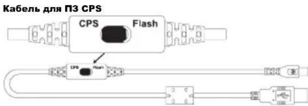
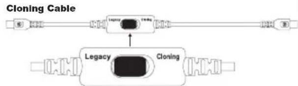
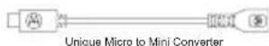
USB-nepexiHnK
KnohyBaHHpaioctaHciB 3a donomoroIO Ka6eIIO dJIa 3'EdHaHHaBox paioctaHciB (R2R) (OdaTkoBe o6naHaHHa
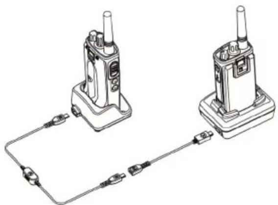
Ihcmpyku3 ekcnnyamaui
UCYHEHNA HECNPABHOCTEN
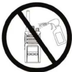
He BnKOpNCToBvIe CnIpT a6o MNUOci 3ac06n
Kaio do paioctaunii notpanna Boda...
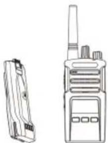
Bumkhitb padionpncptpi i Bnmitb akymyjatopn
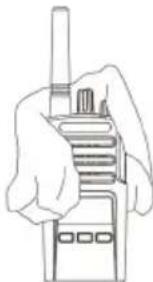
PpOpiB cyXoT KaHHoHO

He KopnctyTecra paoipncTpoem,doKu BIN IOBHICTIO He BUCOXHe
TABJIUNI YACTOT TA KOJIB
Y ubomy po3dihi Habedehi Ta6nuii i3 daHmN 0oO qactOT ta KoDiB. DaHI 3 uX Ta6nucb noTpi6hI DJIa BCTaHOBHeHHra 3B'ay3ky mix npictpoMn DBOcTOpOHbOrO paio3B'3ky cepii Motorola XT ta IHWMN KomepuHmnpaioCTaHciMa. BiNbSiCTb YacToTHnx KaHaJIb CnIBnadaHTb i3 KaHaJAmn paioctanci cepii XTNi.
CmahdapmHa yacmomHa cimka ma kodu wymo3aanyueHHA
© 2013 Motorola Solutions, Inc.
Yci npaba 3axuieni.
IOpndnueckoe yBeDomJIeHne O nporpaMMHom oBeCneueHn C OTKpbITbIM NCXODHBIM KODOM
ДанhoeиздениMotorola codepknT IO c OTkpblbIM nCXoHbIM KOdOM.
yBeOMJIeHnX 6 abTOpcknX npaBax n dpyrnx ycIOBnX NOIb3OBAHn
CM. DOKymeHTaUIO K DaHHOMy I3dJIINIO Motorola Ha Be6-caIte
http://businessonline.motorolasolutions.com
Cm. pa3dErl Resource Center (LcHTp pecypcoB) > Product Information
(Информацья обиздених) > Manual (Pyководстб) > Accessories (АкCEDСУAPы).
CODEPXXAHNE
CoepekHaHne 1
Abtopckne npaba
Ha KOMNbIOTepHoe npoPpaMMHOe
obecneueHne 4
B30NaCHOCTb 5
HOpMaun no Texnke
6e3oNaChOCTn npo6paueHn
c aKKymyIaTOpamN
H3apAHybIMN yCTpoiCTBaMn .6
Yka3aHnno6e3oNaChOH 3Kcnnyataun .8
O63op paAnocTaHcH.. 9
BHeuHn BnD n opraHbI ynpaBneHn .9
Peryjntop Bk./Bbikl./PomKocTb .10
Pyka BbI6opa KaHaNoB 10
Pa3bEm IINI NOIKNIOUeHnna akceccyapOB 10
3TnkeTka MoJeN 10
MinkpofoH 10
AHTeHHa 10
CBeToIIOHbI INHnKaTOp. 10
Bokobbie KhoIkn 10
Литун-ионны (Li-Ion) akkyмлгтор... 11
AkkymyIaTopbI
I 3apArdHbIe ycTpoiCTBa. 12
XapakTepeNCTnKn 3apRJa
aKKymyTopa 12
JIHTM-NOHHbIe aKKyMylrTopbl. 12
YCTaHOBkaJIHTn-NOHOro aKKymyIaTopa 13
I3BneHHeJIHTN-NOHHO aKKyMylTopa 14
CBeToIIOHbIE INdNkAToPbI
paiooctaHcnn 28
Pa6ota B pexkme hands-free/VOX. 29
IcnoJIb3OBAHne COBmecTnMbIX
akceccyapoB VOX. 29
YcTaHOBKa yPoBHa YyBCTBNTeJIbHOCTN
iVox. 30
Pexim "hands free" 6e3
INCNoB3OBAHnAkCeccyapOB
(iVox) 30
YcHHeMnKpOoHa. 30
BkHoueHne nn OTKJIoueHne
TOJIOCOBbIX 06bYBJIeHn B
peKIme IONb3OBaTeIra 31
ToHaJIbHbI CNrHaJI BkJIIOUeHnA
NITaHn 31
C6pocdo3aBODCKNXHacTpoeK. 31
Функци nporpaMMnpOBaHЯ 32
Advanced Configuration Mode
(Pexm pacunpeHHo KOnHpyaun). 32
BkIIOUeHnepeXIMapacuHepHoN
KoHΦnIpyaun Advanced
Configuration Mode 33
BbO3HaueHn YacToT 34
CHTbBaHne 3HaueHn CTCSS/DPL...34
CHTbBaHHe 3HaYeHH
abTOCKaHnpOBaHn 34
CoxpaheHne HacTpoek 35
Ppimep nporpaMMnpoBaHn3HaueHn. 38
Ppimep nporpaMMnpOBaHn
yactotbl 38
Ppimep nporpaMMnoBaHn
KoDa 39
Ppimep nporpaMMnpoBaHna
abTOckaHnpOBaHnra 40
YdaneHne MeShaOuJero KaHaJa .42
IOn DnI noJIb3ObaTeNbckoro
nporpaMMnpoBaHn (CPS). .43
TaNmep BbIKHueHn 44
CnHaJIbI Bbl30Ba 44
CkpeM6JInpoBaHne 44
O6paTHbI NmnyJbc 45
KJIOHINPOBaHne paAnocTaHcui .45
KJIOHINPOBaHHe c NOMOuBIO
MHOROMeCTHOrO 3aprHOrO
ycTpoNCTBa 46
Kabénn CPS n Kabénn dny
KJOHINPOBaHnA
ABTOPCKNE IPNABA HA KOMNbIOTEPHOE IPOPGAMMHOE OBECEPUEHNE
OncaHbIe B DaHOM pyKOoDCTBe n3deNn
Motorola moryt coepkaT 3aunuHbIe
ABTOPCKMn npabAMN KOMnbOTepHbIe
nporpaMMbl KOMnAHn Motorola Solutions,
XpaHauuecra Ha NOnynpOBoHDNKOBbx 3U nn
dpyrnx Hocnten. 3akOnbI CUSA n HeKOTopbIX
dpyrnx cTpan oBecneuHBaiOT HeKOTopbIE
3ckJIIO3NBhie npaba KOMnAHn Motorola
Solutions B OTHOseHN 3aunuHbIX
ABTOPCKIM npabOM KOMNbOTepHBIX nporpaMM,
BKJIOUaR, B qactHOCTn, npabo Ha KOIpOBaHne
n BOCPpON3BeDeHne B IIO60fOpMe
3aunuSeHHbIX aBTOpcKMn npabOM
KOMNbOTepHBIX nporpAMM. B CBz3n C 3TNM
HnKaKHe KOMNbOTepHbIe nporpaMMbl
KOMnAHn Motorola Solutions, coepxuaeeCBA
B n3deNax Motorola, onncanHbIX
B HAcTOrIeM pyKOBoDcTB, He pa3peWaeTcKoIInPoBaTb, BOCnPOn3BOdNtB, N3MeHЯTb,IOBBePrAtb INXKeHepHomy aHaJIIN3yДЛaCOZdaHnA aHaJOra IIN PaCnPoCTpaHЯTbKaKIM 6bl To Hn 6blIO cNoCo6om 6e3 RaBHoro\PncbMeHHOrO pa3peSeHnA KOMNaHn MotorolaSolutions.
Kpome Toro, npno6peTeHne npoDyKTOB
Motorola He npnbEeT, npraMo, KocBeHHo,
npoceccyaIbHO nn KaKIM-Jn60 INbIM
O6pa3OM, K nepeDaue JInCeH3n Ha aBTOpCKHe
npaBa, nATEHTbI nn 3aNaTeHTOBaHHbIe
npinloXeHna Motorola, Kpome o6bUHoi
HENCKJIIOuHTeJIbHOJnUcEH3nHa
INcNoIb3OBAHHe, KOToPA B03HnKaET NO
3aKOHy npn npodaJe npoDyKTA.
БЕЗПАСНСТБ
www.motorolasolutions.com/XTseries
ИнфОРMAцЯ ПOTEXНKE Б3ОПACHOCTNПРИ OБРALLEHINС AKKUMЛЯTOPAMNИ 3APДнblIMNYCTPOICTBAMN
B hactoIeM DOkymeHTe COdePkaTcB BaxHbIe HNCTpyKuIN NO 630nacHO NkCnIyatauIN. BHImaTeNbHO npOHTte 3TN INHCTpyKuIN I COxpaHITe dIaJIbHeIWeI ONCIOJIb3OBaHIn B KaueCTBe CnpaBKn.
Ipeed hauanom nCnoB3ObaHnna 3apndHoro yctpoiCTBa dIa aKKyMnyTopoB 03HaKOMbTeEc bCO BcEMN INHCTpyKzmaN I npEduynpeJxdeHnMaN, pa3MeueHHbIMn Ha
- 3apяДнOM yCTpoIcTBe,
aKKyMnyTOpE n
paNIOCTaHcHn, B KOToPoY yCTaHOBneH aKKyMylrTop.
1.ДЯ CHIXEHNI pNcKa TpaBM NcNoJIb3yIte 3apJHoe yCTpoiCTBO DnI 3apJKn TOJIbKO cepTnΦnIupOBaHHbIX aKKymJrTOPOB Motorola.3apJka aKKymJrTOPOB dpynx TINOB MOXET PnVBecTN K B3pBiBy n, KaK CJIeIcTBHe, TpaBMam I MaTePnaJIbHOMy yUepe6y.
2. Испосьзоваиме akceccуаров, He pekomehoBaHHbIX KomnaHnei Motorola Solutions, moKet ctaTb npuHnO noXapa, IopaxeHnA 3JIeKTPnueCKM TOKOM INI TpaBM.
3.ДЯ CHINKENI pNCKa nopaKeHNA 3JIeKTPnuecknM TOKOM OT BUNK IN Ka6eJIa OTKJUohAte 3apRdHOe yCTpoiCTBO OT 3JIeKTPnuecko CETu, yDepXNBaR Ka6eJIb 3a BUNKy.He TAnHe 3a Ka6eJIb.
- ИспόньзуITE ydINHITeNBbI KAbToNko TOrda, KOrda 3TO DeIcTBtENbHO Heo6xOIMo.Испόнь3OBaHne ydINHITeNBHO Ka6eNc HeDOnyCTnMbIMn napamETpAMM MoKet cTaTb npuHNoI NOkapa I nopaxKeHnE 3JIeKTPnueckm TokOM. EcIn BO3HKnla Heo6xOIMOCb YCpONb3OBA Tb ydINHITeNBbI Ka6eNb, y6eINTecb, YTO INcNoB3yeTcR Ka6eNb COOTBeTCTByUoJcero pa3Mepa. EcIn dInHa Ka6eRr He npeBbIaet 30,48 M,doJxHe NcNoB3OBaTcR Ka6eNb pa3Mepa >1 MM,a npi dInHe Ka6eRr do 45,72 MdoJxHe INcNoB3OBaTcR Ka6eNb pa3Mepa >1,5 MM.
-
Дя снженя риcka BO3HKNHOBEHЯ noxapa, nopaженя злжКТчecKM TOKOM nIN nOlyeHЯ TpaBM He NCNoIb3yIte 3apJdHoe yctpoiCTBO, ecn B Hem IMeIoTc KaKHe-JI6o HeNoIaKn IIN NOBpeXdeHЯ. IpepaIte erO KBaIIuФицрOBaHHOMy IpeIcTaBNTeIIO cepBucHoi cnyk6bl KOMpAHIn Motorola Solutions.
-
He pa3bpaIte 3apJHoe yctpoCTBO: OHO He IODJIeKNT peMOHTy, n 3aIaChIe DeTaIIN K HEmY He npEydCMOTpeHbI. Pa36Opka 3apJdHorO yctpoIcTBA MOKeT npIBecTn K nopaxKeHIO 3JIeKTpUcEckIM TOKOM IIN BO3HNIKHOBEHNIO NOkapa.
- Дя снжehн риcka npaжehн
эл ektpиескIM TOKOM obecToHte yctpoiCTBO
перд поведенm кakux-лбо опетаи по
обсnyЖваню пичтke
Pyka BbI6opa KaHaJIOB
IcnoJb3yeTcAДЯпepeKJIIOUeHnMaMeKdypa3NHybIMKaHaJaAMnpaDIOCTaHcUN.
Pa3bem nIy noKnIoueHnA kCeccCyapOB
IcnoJb3yeTcA DnI NOKJIIOUeHnI COBMeCTUMbIX akceccyapOB.
3TnKeTka MoeJIIM
PpeDCTaBnAeT MoDEnb paAnOCTaHcNn.
MnKpOoH
Pn Otnpabke coo6uHn Heo6xOIMO roBOpNTb B MmKpofoH YETKO n pa360pUBO..
AHTeHHa
B MoJeIpaNIOCTaHcIIN XT420 aHTeHHa He CHIMaeTcR.
CBeToDnOHDhINHdNkTop
IcnoJb3yeTcA DnA O6O3HaueHnA COCToHnA kKymyIaTopa, BKNIOUeHnA, INΦOpMauN O Bbl3OBe N COCToHnA CKaHIpOBaHnA.
Бokobbie KhoNkn
Khonka PTT (Push-To-Talk)
HaKMMTe n yIepKnBaTne KhoNky PTT npa3roBopa n OTNyCTnTe ee dIy npocnyuBaHna.
Bokoea Khoja 1 (SB1)
- BOKOBaK HONKa 1 ABnEeTc8 O6uey KHNKO, KOToPA MoKeT 6bITb HAcTpoeHa c NOMoUsbIO PO IINb3OBaTeNbckOro IporpaMMIpOBaHna (CPS).I0 yMOJUaHIno KHNKa SB1 HAcTpoeHa HaФyHKcNIO "MoHHTOpnHr".
Bokobar KhoIIka 2 (SB2)
Bokobar KhoNka 2 RaBnaTc8 o6uei KhoNkoi, KOtopa MoKet 6bITb HacTpoeHa c NOMOuBIO CPS. IyoMOnuHaHIO KhoNka SB2 HacTpoeHa Ha cyHKnIO "CkAnHpOBaTB/YdaJIntb KaHaIc nomexo".
YcTaHOBKa NHTn-NoHOro aKKyMyJTopa
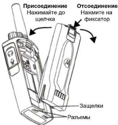
- BbIKIOHTe paIIOCTaHcHIO.
- PacnoJoxKeTaeakMyJrTop TaK,HTo6blIIOrToN Motorola 6bI HnPaBJeH BBePx, IN BCTaBbTe 3aueKN B HxKHeuactn akMyJrTopa B pa3beMbl, pacnoJoxKeHHbE B HxKHeuactn Kopnyca padnoctAHcun.
- HadaBNTe Ha BepxHIOU qactb aKKyMylrTopa do uenka, yTO6bl BCTABNTb eRO B KOpNyc paAnocTaHcnn.
Примechан. Поробпee ob ocobehoc'tax pa6otbI INTN-NOHbIX aKKMyJrTOpOB cM. "IHTN-NOHHbIe aKKMyJrTOpbl"Ha cTp.12.
N3BneHHe NHTn-NOHOro AKKMyJrTopa
- BbiknHouHTe paIIOCTaHcNIO.
- Haxmnte Ha qKcaTop aKcMyIaTopa n ydepknBaIte eRO B 3TOM NIOJXeHN.
- 13BJIeKeIte aKKyMylTOp n3 paNocTaHcII.
Ta6n.1:XapaKTepeNCTnKN JNTn-NOHORO aKKymyJIaTopa C MoUHOCTbIO nepeDaun B0,5BT
Ta6JI. 3: CBeToNoHbI INHdNkATop aKKymyJrTopa
CBeToIIOHaHnHnKaunOTCyTCTByeT:
- Поверьт, паиньно Лп радиocтанцясakуmyЯTopOM nln akkymyЯTOp OTdienbHo yctaHO yCTaHOBJIeHbI B 3apJHoe yctpoiCTBO. (cM. war 4В pa3dene "3apJka c nCnoJb3OBaHNem ODHomeCTHoro 3apJHoro yctpoiCTBa c noDCTaBko" Ha ctp. 16)
-
- 6eHnTecb, yTo aKkMyJrTop, nCNoJIb3yEmbI B ycTpoiCTBe, yKa3aH B Ta6n. 2 Ha cTp. 17.
Pn6JIn3nteJbHoeBpeMzapdKn
Ta6JI. 5: CBeToOnoHbI INHdNkaTOp aKKyMylTopa
CBeToNoDHaNnHnKaunOTCyTCTByeT:
- IpoBepbTe, npaBnIbHO Jn paIIOCTaHcNc aKKyMylrTOpOM HIN aKKyMylrTOp OTJeIbHO yCTaHO bB 3apJdHoe yCTPOiCtBO. (CM. "3apJdKa paIIOCTaHcNm N aKKyMylrTOpOB C nCNoJIb3OBAHNEM MHoromeCTHOrO 3apJdHOrO yCTPOiCtBa (DOnOpHInTeNbHbI akceccyap)" Ha cTp. 20)
- Y6eIntecb, yTo Ka6eIb nHTaHnHaJedXHo nOdkJIIOueH K pa3bemy 3apdHOro yCTpoiCTBa N K COOTBeTCTByUoJe p03eTKe nepemeHHoro Toka, a TAKKe YTO K PO3eTKe nOdBedeH TOK.
- 6eTecb, yTo aKymyIaTOp, nCIOJIb3yeMbI B ycTPOiCTBe, yKa3aH B Ta6n. 2 Ha cTp. 17.
HauJIO PABOTbl
CBeToIOHbI INHdIKaTOP ODHOKpaTHO Mnraet KpacHbIM CBeTOM.
ДлЯ ВьIKПЮЧЕня радиocтAHцИ
nobopaunBaIte peRyJIaTOp BkN./BbIKN./
ГрмКоCTь пOTиВ чAOВ сТpeKN Do tex
nop, nOKa He yCblIuNTe шeJNoK, И He
ВьIKПЮчITc CBETODINODHbI INHdNKaTOp.
PEIYINPOBKA IROMKOCTN
UTo6bI yBENuHTb rPOMKoCTb, NOBepHnTe peYJrTOp BkN./BbIKN./rPOMKOcTB no YacOBo CTpeJIke; UTo6bI yMeHbUHTb rPOMKOcTB, NOBepHnTe peYJrTOp npOTNB YacOBo CTpeJIKN.
Примechаим. He cneyuET DepeXaTb paAnocTaHcUHO cnNtKoM 6n3KO K yxy, Korda OHa HAcTpoEHa Ha 6ObluYrPoMKoCTb IIN BO Bpemr peYnpOBKn rPoMKoCTn.
BbIBOP KAHAJIA
YTo6bI BbIbpaTb KaHaN, NOBopauNBAaTe pyKy Bbl6opa KaHAnOB Do Tex NOp, Noka He HaNDeTe HyxHbI HOMep KaHaJa. NepeKJIIOUeHne KaHaJIOB COpOBoXdAeTCra rONOCOBIM ONOBSeHHeM.
Y KaJDoRo KaHaJa eCt b CBoN HAcTpoiKn
yactOTbI, KoJa ycTpoiCTBa dIJI NCKJIIOUeHnA
nomex n cKaHInoPoBaHnI.
PA3ROBOPMOHHTOPNHT
Ipeed hauaHOM nepedaun Heo6xOIMOBbINOHNb MOHHTOpHr TpaΦnka, YTO6bI36exaT "napaJIeJbHO rpoa3roBopa"c noJIb30BaTeJeM, KOToPbI yKe BeetnepeaCy.
YTo6bI nonyuHTb DoCTyn K TpaΦnky KaHana
HaChaTb MOHnTOPuHr, HaxMMTe N yDepxNBAitE
KhONKy SB1(*). Ecnn HnKaKoJ aKTNBHOCTn HeT,
Bbl YcJIbIShTE cTaTnueCKne nomExn. YTo6bI
PpeKpaTntb MOHnTOPuHr, CHOBa HaxMMTe
KhoNkSy SB1. PocNe OuncTK n TpaΦnka KaHana
PpOdoJXnTE cBOB Bbl3OB NyTEM HaxKaTna
KhoNk PTt. Ppr nepeJaue cBeToDnOHDhbl
HNdkaTOP NOCToRHHO rOpNT KpaChbIM ZBeTOM.
Примочаня:
- UTo6bl npocnywaTb Bc0 aKTHBHOCTb Ha Tekyuem KaHane, Kopotko haxmnte KhoNky SB1, UTo6bl yctahOBNTb 3NaueHne "0" dJa KoDa CTCSS/DPL. 3Ta fynkun HocnT Ha3BaHne "O6napyKeHne CTCSS/DPL (3NaueHne "BE33BYHbI" dJa HactpoKn noDaBHeHna).
(^*) IpeDnonaraetc, yTo KhONka SB1 He 3anporpamMnpoBaHa dIydpYrO pexIma.
ПРИЕМ ВьI3ОВА
- BbI6epnte Heo6xOaIMbI KaHaI, IOBopauVBa pyKy Bbl6opa KaHaIOB. IpeeknIOueHne KaHaIOB COpOBOXdaetcra TOnOCOBbIM ONoBEuHeHem.
- Y6eIITecb B TOM, yTO KHOIIKa PTT OTnyuIeHa, INKdTe roJIOCOBn AKTNBHOCTN.
- Bo Bpemn npneMa BbIIOBa CBeToNOIOHbI INHdNKaTOp rOpNT KpaChbIM LBeTOM.
- UTo6bI npHnABy BbI3OB, DepeXnTe paAnocTaHcNIO BepTKaJIbHO Ha pacCToAHn npImepHo 2,5-5 cm OTO pTa. HaxmTe KhoNky PTT dIpa3roBopa n OTnyctnte ee dI npocnyuBaHn.
Приимейанne.
KoDbI yCTpoiCTBa IJRA NCKJIIOHEnI NOMEx MOrYT TaKKe Ha3bIBaTbcra Koamn CTCSS/DPL uIN PL/DPL.
ДИАПА3OH PA3ГОВОРА
PaiooctaHcHn cepH NT pa3pa6oTaHbI dIy oBecpeHn MaKcImaIbHbIX pa6OuHX xapaKTepnCTnK n yUyWeHn DaIaHa3OHa nepeDaH B noJIeBbIX ycNoBnx. Bo n36exAHne NOMEX He peKOMeHdyetc IcIOJb3OBaTb paioocTaHcHn Ha pacCToHn 6nHexe1,5 MeTPOB. 30Ha nokpItna paioocTaHcHn XT420 coCTabnEET 16,25 KB. M., 13 3tajKe Hn 9 KM Ha POBHO MeCTHOCTN.
Диana3OH pa3roBopa 3aBnCHT OT peIbeΦa MeCTHOCTN. Kpome TOrO,Ha HeTo MOryT IOBJIYrTB 6eTOHHbIe KOHcTpyKUIN, rCyTaNCTBa N3KcPnyatauJa PAAnocTaHcN BHyTpN IOMeUHeH INI TpaHCnOpTHbIX CpeDCTB. ONTImaJIbHbIy Diana3OH paccuHTAH Ha NCIOJIb3OBaHHe B yCNOBnX PLOCKNX OTKpbITbIX MeCT IN COCTaBnE T Do 9 KInOMeTPOB. EcIn Ha NYTu BCTpeuOTcA 3daHnI INI DepeBbI, TO IIpIMeHm CpeHNI Diana3OH.
Дя yctaHOBJIeHn npabINbHOJ DByCTOpOHHe CB3n HAcTPOkK KaHaJa, YacTObI N KOIOB yCTPOiCTBa IJN NCKJIIOUeHn IOMEx DOJIKNbI 6bITb ODiNaKOBbI Ha OBeNX paNoocTaHcIax. 3To 3aBNCt OT COxpaHeHHOr IpOΦnJI, KOTOpbI 6bl 3anporpaMMIpOBaH ha paNoocTaHcIIN:
- KaHAn. TeKyuN KaHaJI, KOToPbI NcNoJIb3yET paAnocTaHcUra, B 3aBnCmOcTn OT MoJeIN paAnocTaHcUin.
-
Yactota. Yactota, IncnoIb3yema paiaoctaHnei dIe nepeaHnnpema.
-
KoJ ycTpoNCTBa dIa NCKJIIOUeHn IOMex.
3TN KObl NOMORAOT MHHMn3npoBaTb NOMEXI nyTeM Bbl6opa pa3JIuHbIX KOM6HaCNI KOIOB.
- Kod ckpeM6npoBaHna. KoIbI, KOTOpbIe I03B0JIoT NcKa3NtB nepedAbaembl CnHaJI TaK, YTO6bI erO HeJIb3a 6blIO npocnywaTb CpaIIOCTaHcN, He HAcTpoEHNo Ha 3OT KOId.
Для полуеня поробно Инфорmaци O настюке частоти КODOB CTCSS/DPL Ha kaHaJax cm. "Вкlioчени ржIMa paширеньй конфигурази Advanced Configuration Mode" Ha ctrp. 33.
CBETOIOHOHbIE INHINKATOPbI PAIDNOCTAHcN
YcTaHOBka ypOBHryBCTBNTbHOCTn iVOX
UyBCTBNTeJIbHOCTb aKCECCyapOB nIN MmKpOfoHa paIIOCTaHcUN MOxHO n3MeHrTb B 3aBnCIMoCTn OT yCNOBni pa60TbI yCTpoiCTBa. UyBCTBNTeJIbHOCTb iVOX MoxHO 3anporpaMMnpOBaTb c NOMOujo IO CPS.
No yMOJUaHnIO yPOBeHb YyBCTBNTeJIbHOCTn paBeH 3. Heo6xOJIMo N3MeHHTb yPOBeHb YyBCTBNTeJIbHOCTn iVOX.
1=Hn3Kyn ypoBeHb YBCTBNTeJbHOCTN
2 = CpeHn ypoBeH yBCTBNTeJIbHOcTn
3 = BbICOKn ypoBeHb yBcTBNTeNbHOCTN
Pexim "hands free" 6e3 nCnoIb3OBAHnA kCeccyapOB (iVOX)
BknIOHTe iVOX,naKab KhoNky PTT npn BkIIOUeHnn paAdIOCTaHcHn.
iVOX MoXHO OTKIIOHHTb Ha BpeMra, HauKaB KhoNky PTT.
KopoTkoe HaxaTne Ha KhoNky PTT CHOba aKTbBnpye iVOX.
Mekdy MOMeHTOM, KOrda noIb3ObaTeJIb HauHnaet ROBOpITb, N MOMeHTOM, KOrda paAnocTaHcIIa HauHnaet nepeJaCy, eCTb He6oJIbwo npomexyTOK BpemEni.
YcHneHne MnkpofoHa
UyBCTBnTeIbHOCTb MmKpOfoHa paAnocTaHcIMMOXHO N3MeHrTb B 3aBNCUMOCTN OTNOTpe6HOCTeI NOIb3OBaTeIeI IIN ycNoBn pa6oTb yCTpoIcTba.
3TyФyHKUHMOXHO HAcTPONTb TOJIbKO C NOMOUsIO IIO CPS. IOn yMOJuaHNIO MKNPOoOH HAcTpoeH Ha yPoBeHb 2 (cpeDHee ycInJeHne).
BkIIOUeHne nII N OTKIOUeHne roIocOBbIX 06bIaHEHn B pexIme noJIb3OBATeJIa
KopoTkoe haxaTne KhoNk SNB1 npn BKIOUcHnn paIIOCTaHcN IN BKIOUcHaET NIN OTKIOUcaET rOIOCOBbIE O6bRAJIeHnB peKIMe IOnb3OBaTeJI (NO yMOJuaHIO rOIOCOBbIE O6bRAJIeHnBAKIOUcHbl).
ToHaIbHbI cHrHaB KJIIOUeHnN NtAHn
YTO6bI BKNIOUHTb IIN BBIKIOUHTb TOHaJIbHbI CNrHaJI BKNIOUChEHN IITAHNIA, OJHOBpeMeHHO HAnKMITE KHOJKN SB1 n SB2 n ydepxnBaIte INx 2-3 cekyHdbI npn BKNIOUeHN paIIOCTaHcUN, NOKa He ycblIiNTe npedBapntelbHO 3anporpamMnpOBaHHbI TOHaJIbHbI CNrHaJI BKNIOUChEHN. Bbl MOKeTe Bbl6paTb ODNH n3 3doCTyINhBX 3ByKOBbIX CNrHaIIOB.
C6pocdo3aBoDcKnxHacTpoeK
3TaФункиЯ NO3BOJЯET BOCCTaHOBHTb BCE NCxODHbIe 3aBOdCKIe HAcTpoiKn paNocTaHcIIN. Yo6bl C6pOcNTb HAcTpoIKN, OndHOBpeMeHNO HaxMITE KHOJIKN PTT, SB1 nSB2 BO BpeM BkJIuOHeHnpaNocTaHcIIN ydePknBaITe Ix, NOKa He ycblIuNTe 3ByKOBoI CNrHaI BbICOKOI ToHaJIbHOCtN.
- BBi6Op yactoTbI,
- KoДы (CTCSS/DPL),
- abTockaHnpoBaHne.
Функцня Frequencies Select (Bb6op
чactOTbl) NO3BOJЯET BbI6paTb HUxHbIe ChactOTbl
ИЗ п徳ВарптIELНо 3аданHOrO спнcka.
Interference Eliminator Code (KoJ yctpoicTbA dIa NckJIoueHnra NOMex) (CTCSS/ DPL) cnooc6CTByeT MInHMn3aunn NOMex, IpeOCTaBnra Ha BbIbOp HeckoJIbKO KOMbHaucn KoIOB, KOtOpbIe pNJIbTpuyOT aTMocepHbIe NOMEXI, Wym HHexKeJaTeNbHbIe COO6UeHn.
Функця Auto-Scan (ABTOCKaHnpOBaHne) NO3BOJnEeT 3aDaTb aBTOMaTHueckN 3aNyCK cKaHnpOBaHn Ha KOHKpeTHOM KaHaJIe npi KaXdOM erO bIbope.
BkIIOUeHnepeKIMpaacupeHHoN KOHnRypaun Advanced Configuration Mode
PeJaKTHIpOBaHHe cNtCKa cKaHIpOBaHnA
Cnncok cKaHnpoBaHnMoXHo
OTpeJaTnpoBaTb c NOMOuIIO CPS.ДЯ
NOLyueHnI DOONHInTeJbHoN INΦOpMaun
CM."ПОДЯ NOLb3OBaTeJbCKOrO
NporpamMnpoBaHnI (CPS)"Ha cTp.43.
YdaJIeHne MeIaIooero KaHaJa
YdaJIeHHe MeIaIOUeRO KaHaJa No3BOJAreT BpeMeHNo YdaJIITb KaHaJIbI N3 CnNcKa cKaHnpOBaHn. 3To fynKuIy IOne3Ha B Tex CNTyaUx, KOrDa HeCyUeCTBeHHbI e nepeRoBOpbl Ha "MeIaIOUeM" KaHaJe MeIaIOT 3ΦΦeKTINBHomy cKaHnpOBaHnI.
YTo6bI ydaNtB KaHaJIb I3 CnNcKaCKaHIpOBaHn:
3anyctntepeximcKaHnpOBaHnHa,HaXaB 3anporpaMMnpOBaHHyHa cKaHnpOBaHne KhoNky SB1 nIb SB2.
- Пдождente, поka paДиocTанцЯ He npeKpaTnТ npiem Ha kaHane, KOtOpbI Bbl XOTnte ydaNTb. HaxmTe u ydepXnbAte KhoNky SB2 dJa ydaJIeHna KaHana. Bbl He moKete ydaNTb KaHaC CBKJIoueHHbIM cKaHnpOBaHneM (domaunn KaHaJ).
- CkaHnPOBaHHe Ha KaHane He 6yJeT npOBODITbCra Do Tex Nop, NOKa Bbl He BblJeTe n3 peKIMa cKaHnPOBaHnA, CHOBA HaxKaB KHOJky SB1 nII SB2 (3anporpaMMnpoBaHHyo Ha cKaHnPOBaHne), nII nOKa paIIOCTaHcNIA He 6yJeT BBkJIooYeHa n CHOBA BKlIOUeHa.
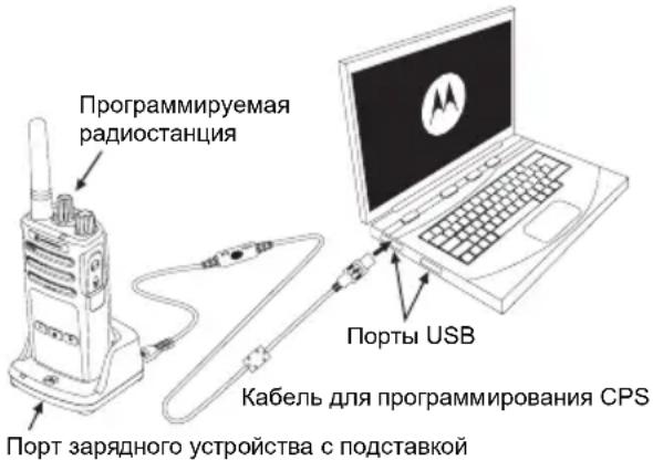
ПОДЛЯ ПОЛьЗOBATEЛБСКОТО
ПОГРAMMЛPOBAHA经(CPS)
Puc.1: Hacmpouka paoduocmauauu dna paobombc IIO CPS
www.motorolasolutions.com/XTseries
Bonee noopohnyu nHOpmauio O KIOHnOBAHN MOxHO HaHTN B INHCTpyKux, npIraHouxxCa MHOrOMeCTHOMy 3apdHOMy yCTpoiCTBy.
ПризakaseMHOROMeCTHOrO3apAnHOrO yctpoiCTBaIcnoJIb3yIteHomepNoKaTaNOry PMLN6384_.
Приимechanical:
B cnyuae Heydaunoro KnoHnpoBaHnca m. "Ecnn KnoHnpoBaHnne npoiNo Heydaunho" Ha cTp. 51.
- YTO6bI KNoHIpOBaHne npoJIo yCneJHo, Heo6xOdImo, YTO6bI cOnocTaNHeHHbIe IcXoHaNn U cIeBae paNDocTaNn pInHaJIeKajN K ODNHO TYu YactOTHO rAnana30Ha.
Hymepaia pa3beMOB MHOROMeTHoro 3apAnHO r yCTPOIcTBA npOn3BOIDTCa CneBa HnpaBo O T Norotuna Motorola.
Ka6eN CPS n Ka6eN dJa KNoHnpOBaHn (doonHnteIbHbI akceccyap)
Ka6eHn CPS n Ka6eHn dIy KNoHnpoBaHn npedHa3HaYeHbI dIy IcnoJb3ObaHn cpaiaocTaHcIaMn cepn XT nIu XTNi. Ka6eHn dIy KNoHnpoBaHn noIepKbBAIoT pa3NHyIbe moJeHn cepn XT n XTNi.
Kabenn CPS npedHa3HaeHbДлЯ
прогамmarpoваня радиocTaHcHcHcHcHcHcHcHcHcHcHcHcHcHcHcHcHcHcHcHcHcHcHcHcHcHcHcHcHcHcHcHcHcHcHcHcHcHcHcHcHcHcHcHcHcHcHcHcHcHcHd
Y6eHTecb, YTO nepeKJIIOUaTeIb Ka6eIa
HaxoITcB bNoIOKeHH "Flash" uIN "CPS".
Пуnpогамmarpoваня радиocTaHcHcHcHcHcHcHcHcHcHcHcHcHcHcHcHcHcHcHcHcHcHcHcHcHcHcHcHcHcHcHcHcHcHcHcHcHcHcHcHcHcHcHcH
XTNi c NOMOuTo Ka6eIa CPS y6eHTecb, YTO
peKJIIOUaTeIb Ka6eIa HaxoITca B NoIOKeHH
"CPS" u K HeMy noIDcoEInHeN ppeO6pa3OBaTeIb
USB n3 KomnNeKta Ka6eIa CPS.
Ka6eIb IaI KnoHnpoBaHn IopIepKuBaET KNoHnpoBaHne:
-paiaoctaHcnpXT.Y6eHTecb, UTOpekeKIOUATEJIb Ka6eIaHaoNTcB B NOIOXeHn "KIOHUPOBAHne" IIN "CoBMeCTIMOCTb".
- padnoctaHcH cepHHXTNi. Y6eHntecb, yTo nepeKIOuATeHb HaxOHTcB B NOLOKeHN "CoBmecTImocTb", n K KaJdOMy KOHcy Ka6eHn IJIa KNOHPOBaHnI POIDCOeINHeH npoe6pa3OBaTeJB USB.
-paiaoctaHcnpXTnXTNi.Y6eintecb, TTO npeeknquatelkab6enna HaxoNTcB BnoJooKHeNn "COBmecTImOCTb", Ncnoj3yIte npoe6pa3OBaTeNB USB nOHNomeCTHO 3apAHorO yctpoiCTBa XTNi. B KOMnKeKT Ka6eIaNKnOHpOBaHH BxOHT 1 ppe6pa3OBaTeNB USB.
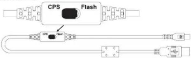
Ka6enb CPS
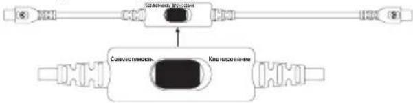
Ka6eIbIa KIOHnpOBaHn
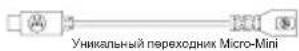
Npeo6pa30BaTeB USB
KloHnpOBaHne paNocTaHcni c NcNoJIb3OBAHnem Ka6eIaJ KIOHnpOBaHnra (dONoJIHnTeJIbHbI akceccyap)
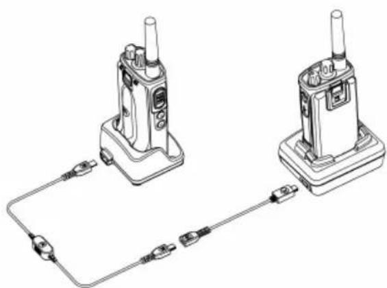
Hcmpkykuu no 3kcnnyamaquu
He norgykaaTe yCTPOINCTBO B BOdy
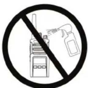
He donyckaetc npimehene cnpTa nnn uNCTaux CpeDCTB
Ecn paioctaunnona B Body...
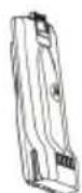
BbIKIIOUHTe paAnIOCTaHcIIO nN3BJIeKNTe aKKyMylTOpbl
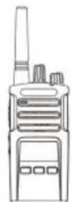
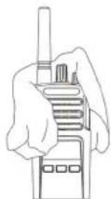
PpOtpnTe MmKoI cyXoT KaHbIO

He nCnoB3yIte yCtpoIcTBO 10 NOHOro BbICbIXaHn
TABJIINZI KOIOB I YACTOT
TbIuB B 3tOM pa3dene npedocTabnIO nHOpMaUO O yactotax N KoJax. OHy uObbl npi IcNoB3OBaHm npneMonepedaoux paNocTaHm Motorola cepnn XT c npoHm KopnpaTHBbIMn paNocTaHm. BolshnCTBO 3NaueHn YactOT COBnadaIoT CO 3NaueHnMy dJa paNocTaHm cepnn XTNi.
Yacmoma kaHana u kOy ycmpoUcmea dna uCKnueHu nomEx no yMOnuHaHIO
3APYdHbIE YCTPOIcTBA
| Homep no
kaTalony | OnncaHne |
| PMLN6385_ | Стадартуй компльekt
ОдномecтHoro зapяд Horo
устриства с постов(
(Bелкообр发布时间/EC) |
| PMLN6393_ | Стадартуй компльekt
МногомecтHoro зapяд Horo
устриства с постов INT
(Bелкообр发布时间/EC) |
AKCECCYAPblI JJIPEHEOCKN
Motorola Solutions, Inc.
1303 E. Algonquin Rd.
Schaumburg, IL 60196-1078, U.S.A.
http://www.motorolasolutions.com

68012009070-A