
ALIZE 3000 2800W - Generator SDMO - Free user manual and instructions
Find the device manual for free ALIZE 3000 2800W SDMO in PDF.
User questions about ALIZE 3000 2800W SDMO
0 question about this device. Answer the ones you know or ask your own.
Ask a new question about this device
Download the instructions for your Generator in PDF format for free! Find your manual ALIZE 3000 2800W - SDMO and take your electronic device back in hand. On this page are published all the documents necessary for the use of your device. ALIZE 3000 2800W by SDMO.
USER MANUAL ALIZE 3000 2800W SDMO
UNDERHALLSMANUAL FÖR
GENERATORAGGREGATEN
CS
NÁVOD K POUZITÍ ELEKTROGENERÁTORU
HU
ÁRAMTERMELÖ EGYSEGEK
FELHASZNALOI ES
KARBANTARTASI
KÉZIKÖNYVE
EN
GENERATING SET USER
AND
MAINTENANCE MANUAL
PT
GENERATORAGREGAATIDE
KASUTUS-JA
HOOLDUSJUHEND
PL
INSTRUKCJA OBSLUGI I
KONSERWACJI ZESPOŁOW
PRADOTWORCYCH
ES
MANUAL DE USO Y
DE MANTENIMIENTO
DELOS
GRUPOS ELECTROGENOS
NL
HANDBOEK VOOR GEBRUIK
EN ONDERHOUD
VAN DE AGGREGATEN
DA
BRUGER-OG
VEDLIGEHOLDELSESMANUAL
FOR
GENERATORAGGREGATER
LV
GENERATORAGREGATU
LIETOSANAS UN
UZTUREŠANAS
INSTRUKCIJA
SK
NAVOD NA POUZIVANIE A
UDRZBU
ELEKTROGENERÁTOROV
DE
BETRIEBS
UND
WARTUNG SANLEITUNG
RU
PYKOBOJCTBOIIO
3KCIJIYATAIINI
OBCLYKIBAHNIO
THEHEPATOPHBIXBJIOKOB
EL
EIXEPIIΔIO XPHΣHΣ KAI
SYNTHPHESTQN
HAEKTPOTENNHTPIΩN
LT
GENERATORI
NAUDOJIMO IR
TECHINIO APTARNAVIMO
INSTRUKCIJOS
SL
PRIROCNIK ZA UPORABO
IN VZDRZEVANJE
ELEKTRICNIH AGREGATOV


33522130101_2_1
A
A
A
B
C
D
E
F
G
| Contents | |
| 1. Preface 2. General description 3. Preparation before starting 4. Using the generator set 5. Safety features (if fitted, see specifications table) 6. Maintenance schedule | 7. Maintenance procedures 8. Storing the generating set 9. Fault finding 10. Specifications 11. Cable sizes 12. EC Declaration of conformity |
1. Preface
1.1. Recommendations
Thank you for buying one of our generating sets. We recommend that you read this manual carefully and follow the safety and maintenance advice and user instructions for your generating set very closely.
The information contained in this manual is taken from technical data available at the time of print. In the intention of permanently improving the quality of our products, this information may be amended without warning.
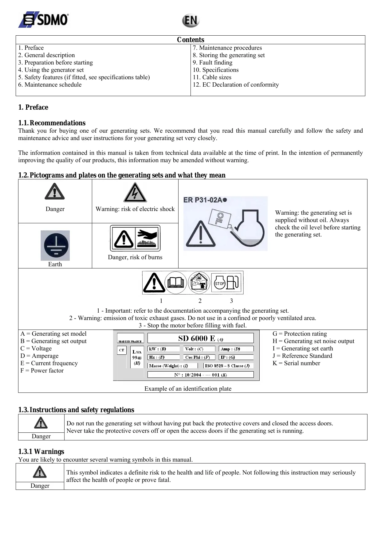
1.2. Pictograms and plates on the generating sets and what they mean
| Danger | Warning: risk of electric shock | ER P31-02A Warning: the generating set is supplied without oil. Always check the oil level before starting the generating set. | ||
| Earth | Danger, risk of burns | |||
| 1 2 3 1 - Important: refer to the documentation accompanying the generating set. 2 - Warning: emission of toxic exhaust gases. Do not use in a confined or poorly ventilated area. 3 - Stop the motor before filling with fuel. | ||||
| A = Generating set model B = Generating set output C = Voltage D = Amperage E = Current frequency F = Power factor | MADE IN FRANCE CE LWA 99dB (H) | SD 6000 E (4) kW : (B) Volts : (C) Amp : (D) Hz : (E) Cos Phi : (F) IP : (G) Masse (Weight) : (I) ISO 8528 - 8 Classe (J) N° : 10/2004 -- 001 (K) | G = Protection rating H = Generating set noise output I = Generating set earth J = Reference Standard K = Serial number | |
| Example of an identification plate | ||||
1.3. Instructions and safety regulations
| Danger | Do not run the generating set without having put back the protective covers and closed the access doors. Never take the protective covers off or open the access doors if the generating set is running. |
1.3.1Warnings
You are likely to encounter several warning symbols in this manual.
| ! | This symbol indicates a definite risk to the health and life of people. Not following this instruction may seriously affect the health of people or prove fatal. |
| Danger |

Warning
This symbol draws attention to the potential risk to the health and life of people. Not following this instruction may seriously affect the health of people or prove fatal.

Warning
This symbol indicates a dangerous situation if the warning is not heeded. Not following this instruction could result in non-serious injury or damage.
1.3.2 General advice
One of the fundamental safety considerations is observation of the interval between maintenance procedures (see maintenance schedule). Furthermore, never attempt to carry out repairs or maintenance procedures without the necessary experience and/or tools.
When you take delivery of your generating set, check that it is complete and not damaged in any way. A generating set should be handled gently, avoiding sudden movements, and the place where it is to be stored or used should be carefully prepared beforehand.

Warning
Before use, it is essential that you know how to stop the generating set immediately and that you thoroughly understand all the controls and operations.
Never let other people use the generating set without giving them all necessary instructions beforehand.
Never let children touch the generating set, even when it is not in operation. Do not operate the generating set near animals (as it could cause them to panic).
Never start the motor without an air filter or exhaust.
Never invert the positive and negative battery terminals (if fitted) when connecting them. Such an inversion can lead to severe damage to the electrical equipment.
Never cover the generating set with any type of material while it is in operation or just after it has been turned off. Wait until the motor is cold.
Never coat the generating set with oil in an attempt to protect it from corrosion. Some preservative oils are flammable. Also, some are dangerous to inhale.
In all cases, respect the local regulations currently in place concerning the use of generating sets.
1.3.3 Safety guidelines to prevent electrocution

Danger
While they are in operation, generating sets produce electric current.
Connect the generating set to earth each time you use it, in order to prevent electrocution.
Never touch stripped cables or disconnected connectors. Never handle a generating set with wet hands or feet. Never expose the equipment to liquid splashes or rainfall, and do not place it on wet ground. Always keep the electrical cables and the connections in good condition.
Do not use equipment in a poor state of repair which could lead to electrocution or damage to the equipment.
Use a differential protection device between the generating set and the appliances if the cable or cables used are more than 1 metre in length. This device must be positioned at a maximum distance of 1 metre from the generating set electrical sockets. Use flexible, durable cables, with rubber sheathing, conforming to the IEC 60245-4 standard or equivalent cables. Do not connect the generating set to other power sources, such as the mains. In specific cases where there is provision for a reserve connection to existing electrical networks, this must only be carried out by a qualified electrician, who should take the operating differences of the equipment into account, according to whether the public distribution network or generating set is being used.
Special circuit breakers designed for use with generating sets are used to prevent electrocution. If these circuit breakers need to be replaced, circuit breakers with identical nominal ratings and specifications must be used.
1.3.4 Safety guidelines to prevent fire

Danger
Keep all inflammable materials (e.g.: petrol, oil, fabric etc.) out of the way when the generating set is in operation. The motor should not be operated in areas containing explosive products. There is a risk of sparks forming where all electrical and mechanical components are not shielded. Never cover the generating set with any materials while it is operating or just after it has been switched off (wait for the motor cool down).
1.3.5 Safety guidelines for exhaust gases

Danger
Exhaust gases contain carbon monoxide, which is a highly toxic substance. This substance can cause death if it is present in excessive concentrations in the air inhaled.
For this reason, always use the generating set in a well ventilated area, where gases will not be able to accumulate.
Good ventilation is required for your generating set to work properly. Without this, the motor would very quickly run at too high a temperature, which could lead to accidents or damage to the equipment and to surrounding items. However, if it is necessary to operate it inside a building, adequate ventilation must be provided, so that people and animals are not affected. It is imperative that exhaust gases are discharged outside.
1.3.6 Filling with fuel
| The fuel is highly flammable and its vapours are combustible. Smoking, using a naked flame or producing sparks are forbidden while the fuel tank is being filled. Filling should be carried out with the motor turned off. All traces of fuel should be wiped off with a clean cloth. | |
| Danger | |
Always place the generating set on a flat, level and horizontal surface to avoid fuel spillage from the tank onto the motor. Storage and handling of petroleum products must be carried out in accordance with the law. Close the fuel tap (if fitted) each time the tank has been filled. Fill the tank using a funnel, taking care not to spill any fuel. Then screw the petrol cap back on to the fuel tank as soon as filling is complete. Never top up fuel when the generating set is in operation or hot.
1.3.7 Safety guidelines against burns
| Warning | Never touch the motor or the silencer while the generating set is in operation, or when it has just stopped. |
Hot oil burns, avoid contact with the skin. Check that the system is no longer pressurised before carrying out any procedures. Never start or run the motor when the oil filler cap is off as oil may splash out.
1.3.8 Safety guidelines for handling batteries
| Danger | Never place the battery close to a flame or fire Use only insulated tools Never use sulphuric acid or acid water to top up the electrolyte level. |
1.3.9 Protecting the environment
Never drain or discard used oil onto the ground, but put it into a designated container. As far as possible, try to avoid sound reverberating through walls and buildings, as the noise will be amplified. If the exhaust silencer of your generating set is not fitted with a spark arrester and you need to use it in wooded, bushy or uncultivated areas, be extremely careful and make sure that sparks do not cause a fire (clear vegetation from a fairly large area where you wish to place your generating set).
1.3.10 Danger of moving parts
| Warning | Never go near a moving part that is in operation if you have loose clothing or long hair that is not enclosed in a protective hair net. Do not try to stop, slow down or impede a moving part when it is in operation. |
1.3.11 Capacity of the generating set (overload)
Never exceed the rated load of the generating set (in Amps and/or Watts) when it is running continuously.
Before connecting and operating the generating set, calculate the electrical power required by the electric appliances (in Watts). This electrical power rating is usually found on the manufacturer's plate on bulbs, electrical appliances, motors etc. The sum total of power required by these appliances should not exceed the nominal power rating of the generating set.
1.3.12 Operating conditions
The stated outputs of the generating sets are obtained in example conditions according to ISO 3046-1:
+27°C, 100 m above sea-level, humidity level equal to 60% or
+20^, 300 ~m above sea-level, humidity level equal to 60% .
Performance is reduced by approximately 4% for every additional 10^ and/or approximately 1% for every additional 100m in altitude.
2. General description
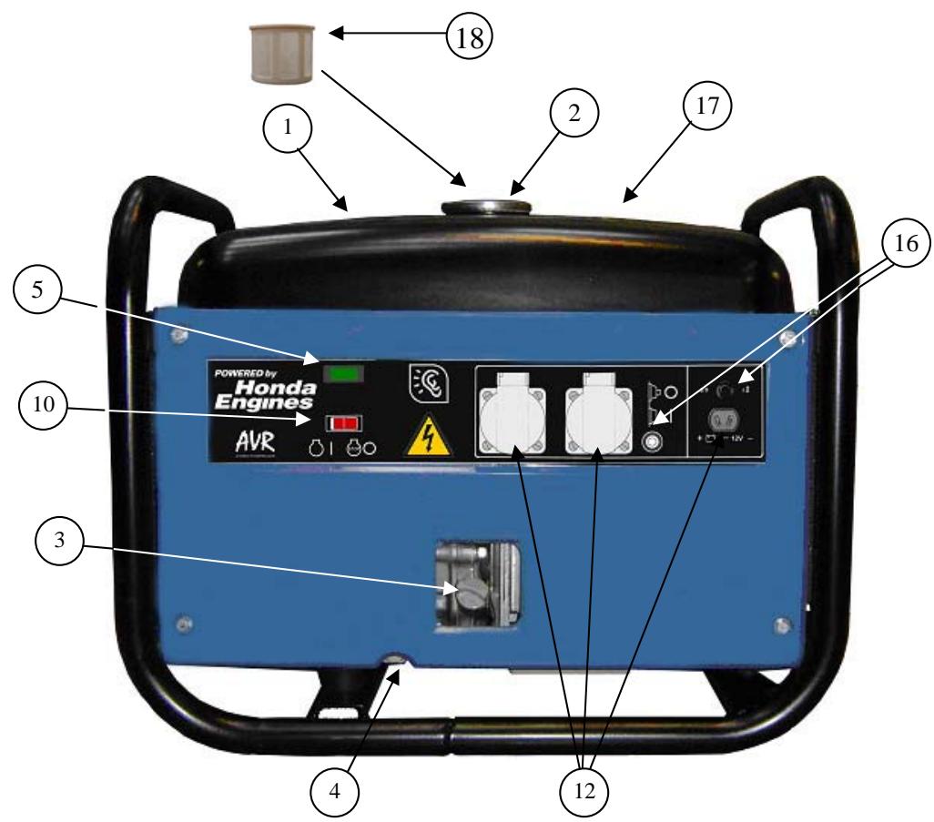
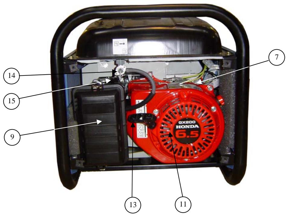
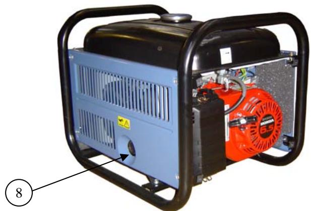
2.1.Description
| Fuel tank (no. 1, diag. A) | Motor (no. 7, diag. A) | Starting handle (no. 13, diag. A) |
| Fuel tank cap (no. 2, diag. A) | Silencer (no. 8, diag. A) | Fuel tap (no. 14, diag. A) |
| Oil filler cap (no. 3, diag. A) | Air filter (no. 9, diag. A) | Choke (no. 15, diag. A) |
| Oil drain plug (no. 4, diag. A) | Ignition switch (no. 10, diag. A) | Circuit breaker (no. 16, diag. A) |
| Voltage present indicator light (no. 5, diag. A) | Starter recoil reel (no. 11, diag. A) | Fuel level indicator (no. 17, diag. A) |
| Alternator (no. 6, diag. A) | Mains sockets (no. 12, diag. A) | Fuel strainer (no 18, diag A) |
3. Preparation before starting
3.1. Checking the oil level
| ! | Always check the engine oil level before starting. |
Tasks such as topping up the oil should be carried out with the generating set on a horizontal surface.
1 Remove cap (no. 3, diag. A) by unscrewing it.
Check the level and top it up if necessary.
Fill the oil sump to the top using a funnel.
Screw the cap tightly back onto the filler tube.
Check that there are no leaks.
Wipe off excess oil with a clean cloth.
3.2. Checking the fuel level
| Danger | Stop the motor before filling up with fuel and fill up in a well-ventilated area. Do not smoke, or bring naked flames or sparks near to the area where you are filling up with fuel or where the fuel is stored. Only use clean fuel without any water. Do not overfill the tank (there should not be any fuel in the filler neck). When you have filled up, ensure that the tank cap is closed correctly. Take care not to spill any fuel when filling the tank. Before starting up the generating set, and if any fuel has been spilt, make sure that it has dried and that the vapours have cleared away. |
Check the level of fuel on the fuel indicator (no. 17, diag. A) and fill with fuel until "F" is displayed:
1 Unscrew fuel tank (no. 1, diag. A) cap (2, diag. A).
2 Fill tank (no. 1, diag. A) using a funnel, taking care not to spill any fuel.
Screw the fuel filler cap back onto the fuel tank.
3.3. Earthing the generating set
To earth the generating set, use a 10mm^2 copper wire attached to the generating set earth connection and to an earthing rod of galvanised steel set in the ground to a depth of 1 metre. This also dissipates the static electricity that builds up in the electrical machines.
3.4. Positioning the generating set for operation
Place the generating set on a flat, horizontal surface which is firm enough to prevent the set sinking down (under no circumstances should the set tilt any direction by more than 10^ ).
Choose a site that is clean, well-ventilated and sheltered from bad weather, and store the additional supplies of oil and fuel within close proximity, although respecting a certain distance for safety.
4. Using the generator set
4.1. Starting procedure
1 Open the petrol tap (no. 14, diag. A).
2 Place the knob of the choke (no. 15, diag. A) on closed position.
Note: Do not use the choke when the engine is warm or when the atmospheric temperature is high.
3 Place the engine switch (no. 10, diag. A) on "ON" or "T".
4 Seize the starting handle (no. 13, diag. A) correctly and pull it slowly until some resistance is felt, then let it return gradually.
Take the starting handle again correctly, then pull the cord sharply and rapidly (pull it right out, using both hands if necessary). Allow the handle to return slowly by hand. If the motor has not started, repeat the procedure until the motor starts by gradually opening the choke.
6 When the engine has started, gradually open the choke (no. 15, diag. A).
4.2. Operation
4.2.1 Alternating current operation
When the running speed of the generating set has stabilised (3 mins):
1 Check that the circuit breaker (no. 16, diag. A) is connected.
Connect the plug(s) to the generating set socket(s).
4.2.2 Direct current operation
The 12V direct current is only used for charging car batteries.
| Warning | The generating set should be switched off before connecting the electric cables. Do not try to start a car engine if the generating set is connected to the battery. |
1 Connect the cables to the battery terminals then to the generating set alternating current sockets observing the polarities (the generating set + cable to the battery + cable and the generating set - cable to the battery - cable)
2 Start the generating set to charge the battery.
4.3. Switching off
| Warning | When the generating set is turned off, the engine continues to give off heat. Appropriate ventilation should be provided after the generating set is turned off. To stop the generating set urgently, place the engine switch on "OFF" or "O". |
1 Take the plugs out of the sockets and allow the engine to run without any charge for 1 to 2 minutes.
Place the engine switch (no. 10, diag. A) on "OFF" or "O" and the set will stop.
Close the fuel tap (no. 14, diag. A).
5. Safety features (if fitted, see specifications table)
5.1.Oil cut-out
This mechanism is designed to prevent any damage to the motor resulting from lack of oil in the motor sump. It automatically cuts out the motor. If the motor stops and will not restart, check the motor oil level before looking for any other cause of the problem.
5.2. Circuit breaker
The electrical circuit of the set is protected by several magnetothermal, differential or thermal cut-out switches. Any overload and/or short circuits cause the supply of electrical energy to be cut.
6. Maintenance schedule
6.1. Reminder of use
The maintenance interval frequency and the operations to be carried out are outlined in the maintenance programme.
However, it should be added that it is the environment in which the generating set is operating which determines this programme. Accordingly, if the set is used in extreme conditions, shorter intervals between maintenance procedures should be adopted.
These maintenance schedules apply only to generating sets running on fuel and oil, that conform to the specifications given in this booklet.
6.2.Maintenance table
| Part\Carry out these maintenance procedures atwhichever of the two intervals isreached first | Each time it isused | After thefirst 20hours of use | Every 3months or50 hours | Every 6months or100 hours | Every 12months or300 hours | |
| Engine oil | Check the level | ● | ||||
| Change | ● | ● | ||||
| Air filter | Check | ● | ||||
| Clean | ● (1) | |||||
| Fuel filter | Clean | ● | ||||
| Spark arrester | Clean | ●(*) | ||||
| Spark plugs | Check / clean | ● | ||||
| Valve clearance | Check / adjust | ● (*) | ||||
| Strainer and petrol tank | Clean | ● (*) | ||||
| Cleaning the generating set | ● | |||||
| Fuel line | Check (replace if necessary) | Every 2 years (*) | ||||
Note: * This operation should be carried out by one of our agents
(1): Perform air filter maintenance more frequently for operation in dusty locations.
7. Maintenance procedures
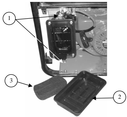
7.1. Cleaning the air filter
| Danger | Never use petrol or solvents with a low flash point for cleaning the air filter element as this could result in a fire or explosion. |
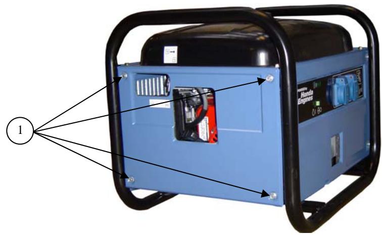
1 Undo the four 10mm bolts holding the closure panel in place starter end, and remove the panel (diag. B).
Unfasten both retaining clips (no. 1, diag. F) from air filter cover (no. 2, diag. F) and remove the cover.
3 Remove foam element (no. 3, diag. F). Check carefully that it has no rips or holes. Replace it if it is damaged.
④ Wash the element in a solution of household cleaning product and warm water, then rinse thoroughly, or wash it in non-flammable solvent or solvent with a high flash point. Leave the element to dry fully.
Soak the element in clean motor oil and remove the excess oil. If too much oil remains in the foam, the motor will smoke when it is first started.
⑥ Refit the filter cover and ensure that it is clipped securely in place.
7 Refit the closure panel and ensure that it is held in place.
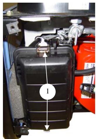
7.2. Renewing the motor oil
Change the oil when the motor is still warm, to ensure that drainage is rapid and complete.
1 Undo the four 10mm bolts holding the closure panel in place exhaust end, and remove the panel.
2 Remove filler cap (no. 1, diag. C) and drain plug (no. 2, diag. C) and drain the oil into a suitable container.
3 On completion, retighten drain plug (no. 2, diag. C).
4 Fill the motor oil sump with the recommended oil, then check the level.
Fit and tighten the filler cap (no. 1, diag. C).
After filling, check that there are no oil leaks.
Wipe off any traces of oil with a clean cloth.
Refit the panel exhaust end and ensure that it is held in place.
7.3. Cleaning the fuel filter
| ! | Fuel is a highly flammable substance which may combust in certain conditions. Do not smoke or bring fuel near to naked flames or sparks. After refitting the filter, check that there are no leaks and that the area is dry before starting the generating set. |
| Danger |
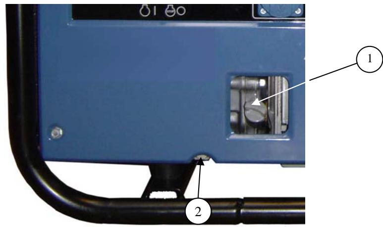
1 Close the fuel tap (no. 1, diag. D).
2 Undo the four closure panel mounting bolts exhaust end and starter handle end, and remove the panels.
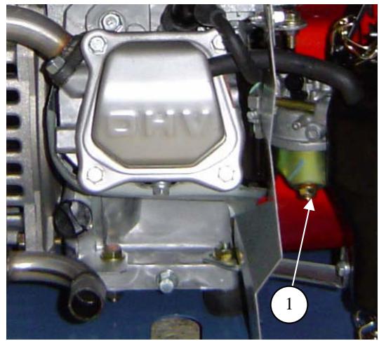
Place a suitable container underneath the carburettor then undo the carburettor drain screw fully (no. 1, diag. E).
Open the fuel tap (no. 1, diag. D) to empty the contents of the tank into the container. Refit and retighten the carburettor drain screw (no. 1, diag. E) when empty.
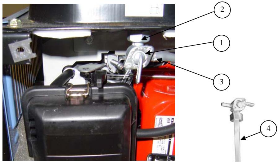
Remove the retaining circlip (no. 3, diag. D) from the fuel supply pipes (no. 3, diag. D) on the tap (no. 1, diag. D), and disconnect the pipes.
Disassemble the fuel tap with its filter then remove and clean the filter (no. 4, diag. D) using a low pressure air gun.
7 Refit the filter (no. 4, diag. D) to the fuel tap (no. 1, diag. D) then refit and tighten the fuel tap.
Refit the fuel pipes and make sure that they are held in place by the circlip (no. 3, diag. D).
9 Add a little fuel to the tank and open the tap to check for leaks.
10 Refit the closure panels and ensure that they are held in place.
7.4. Cleaning the fuel strainer
| ! | Fuel is a highly flammable substance which may combust under certain conditions. Do not smoke or bring naked flames or sparks near to it. |
| Danger |
1 Unscrew fuel tank cap (no. 2, diag. A).
2 Remove fuel strainer (no. 18, diag. A) and remove any impurities by washing it with solvent.
3 Refit the fuel strainer through the tank filler cap opening.
4 Refit the fuel tank cap.
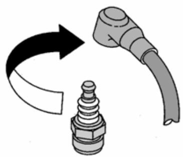
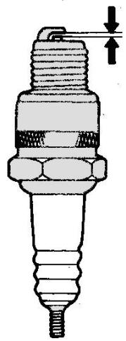
7.5. Checking the spark plug
1 Undo the four 10mm bolts holding the closure panel in place exhaust end, and remove the panel.
2 Remove the spark plug cap and use a spark plug spanner to remove the spark plug.
3 Inspect the spark plug and discard it if the electrodes are worn or if the insulation is melted or chipped. If it is to be re-used, clean the spark plug with a metallic brush.
Measure the electrode gap with a feeler gauge. The electrode gap should be from 0.70 to 0.80mm . Check that the spark plug washer is in good condition and screw the spark plug in by hand, in order to avoid damaging the threads.
After fitting the spark plug, tighten it with a spark plug spanner to compress the washer.
Note: When fitting a new spark plug, tighten it by 1/2 turn after it is seated, in order to compress the washer. If refitting an old spark plug, tighten it by a 1/8 - 1/4 turn when it is position, in order to compress the washer.
⑥ Refit the closure panel exhaust end and ensure that it is held in place.
7.6. Checking bolts, nuts and screws
Daily, detailed checks of all nuts, bolts and screws are essential in order to prevent any accidents or breakdowns.
1 Inspect the generating set as a whole before and after each use.
2 Tighten any loose nuts or screws.
NB: the tightening of cylinder head bolts should be carried out by a specialist. Contact your local agent.
7.7. Cleaning the generating set
1 Remove all dust and debris from around the exhaust and clean the generating set using a cloth and a brush (cleaning with a water jet is not recommended, and cleaning with high-pressure cleaning equipment is forbidden).
2 Carefully clean the motor air inlets and outlets and the alternator.
3 Check the general condition of the generating set and, if necessary, replace any faulty parts.
8. Storing the generating set
Generating sets which are to remain unused for a long period of time must undergo certain procedures, in order to keep them in good condition. Ensure that the storage area is not dusty or humid. Clean the exterior of the generating set and apply a rustproofing product.
1 Remove the closure panels exhaust end and starter end ( 10mm bolts).
Open the fuel tap and drain the fuel from the tank into a suitable container.
3 Drain the carburettor by loosening the drain screw. Recover the fuel in a suitable container.
Change the motor oil.
Remove the spark plug and pour approximately 15ml of oil into the cylinder, then refit the spark plug.
⑥ Refit the closure panels exhaust end and starter end.
7 Leave the motor running at several speeds to distribute the oil in the cylinder.
Clean the generating set and cover the motor to protect it from dust.
Store the generating set in a clean, dry place.
- Fault finding
| The engine will not start | Probable causes | Remedial action |
| The generating set is being charged during start-up | Take it off charge | |
| Fuel level too low | Fill up with fuel | |
| The fuel tap is closed | Open the fuel tap | |
| Fuel supply blocked or leaking | Have the system repaired | |
| Blocked air filter | Clean the air filter | |
| Control on "OFF" | Place the control on "ON" | |
| Defective spark plug | Replace the spark plug | |
| The engine cuts out | Probable causes | Remedial action |
| Blocked ventilation inlets | Clean the air inlet and outlet guards | |
| Probable overcharge | Check the charge | |
| No electric current | Probable causes | Remedial action |
| Circuit-breaker tripped | Reset the circuit breaker | |
| Circuit-breaker faulty | Have it checked, repaired or replaced | |
| Faulty socket | Have it checked, repaired or replaced | |
| Faulty appliance supply lead | Change the lead | |
| Faulty alternator | Have it checked, repaired or replaced | |
| Circuit breaker trips out | Probable causes | Remedial action |
| Faulty equipment or lead | Have it checked, repaired or replaced |
- Specifications
| Model | ALIZE 3000 |
| Engine type | HONDA GX 200 |
| Output (Watts) | 2800 |
| Direct current | 12V / 10A |
| Alternating current | 230V/12.2A |
| Socket type | 2x10/16A 230V |
| Circuit breaker | ● |
| Oil guard | ● |
| Battery | X |
| Acoustic pressure at 1 m | 82 dB(A) |
| Weight in kg (without fuel) | 55 |
| Dimensions 1 x w x h in cm | 57x45x46 |
| Recommended oil | SAE 15W40 |
| Oil sump capacity in L | 0.6 |
| Recommended fuel | Unleaded petrol |
| Fuel tank capacity in litres | 12 |
| Spark plug | NGK-BPR6ES / DENSO : W20 EPR-U |
: standard o: optional X: impossible
- Cable sizes
| Rated current (A) | Cable lengths | ||
| 0 - 50 metres | 51 - 100 metres | 101 - 150 metres | |
| 6 | 1.5 mm² | 1.5 mm² | 2.5 mm² |
| 8 | 1.5 mm² | 2.5 mm² | 4.0 mm² |
| 10 | 2.5 mm² | 4.0 mm² | 6.0 mm² |
| 12 | 2.5 mm² | 6.0 mm² | 10.0 mm² |
| 16 | 2.5 mm² | 10.0 mm² | 10.0 mm² |
| 18 | 4.0 mm² | 10.0 mm² | 10.0 mm² |
| 24 | 4.0 mm² | 10.0 mm² | 16.0 mm² |
| 26 | 6.0 mm² | 16.0 mm² | 16.0 mm² |
| 28 | 6.0 mm² | 16.0 mm² | 16.0 mm² |
12. EC Declaration of conformity
Name and address of manufacturer
SDMO, 12 bis rue de la Villeneuve, CS 92848, 29228 BREST CEDEX 2
Description of the equipment
| Product | Generating set |
| Make | SDMO |
| Type | ALIZE 3000 |
| Electrical output supplied Rated output: 2240 W | |
G. G. Le Gall, the manufacturer's authorised representative, hereby declares that the product conforms to the following EU Directives: 98/37/EC / Machinery Directive.
73/23/EEC / Low Voltage Directive (modified by Directive 93/68/EEC)
89/336/EEC / Directive on Electromagnetic Compatibility (modified by directives 92/3/EEC and 93/68/EEC)
2000/14/EC / Directive relating to the Noise Emission of Outdoor Equipment
For Directive 14/2000/EC
- Notified Body:
CETIM SERVICE DIFFUSION
BP 67 F60304 - SENLIS
-
Compliance procedure: Appendix VI
-
Sound pressure level guaranteed (Lwa):95 dBA
References to harmonized standards used
EN12601/EN1679-1/EN 60204-1
03/2006
G. Le Gall

PnIOJyueHHn rHeepaTOHOn yCTaHOBKn IPOBepbTe ee COCTOHN He KOMIIIEKTHOCt bIOCTaBKn. IpeMeIeHN HeHEpaTOpHOYcTAHOBKn DOJIHKo OcyIeCTBJIaTbcra C OCTOPOKHOCTbIO H63 pblKBoC IIpeBaHPteJIbHO IOIITOTOBKO MeCTa IJIe ee XpaHeHHN HIN 3KCIJIyaTaIHN.
| П配电柜 | П配电柜 П配电柜 П配电柜 П配电柜 П配电柜 П配电柜 П配电柜 П配电柜 П配电柜 П配电柜 П配电柜 П配电柜 П配电柜 П配电柜 П配电柜 П配电柜 П配电柜 П配电柜 П配电柜 П配电柜 П配电柜 П配电柜 П配电柜 П配电柜 П配电柜 П配电柜 |
HnkOrda He IOnyckaiTe K 3KcIIpyataunn rehepaTOPOHou yCTaHOBN JINU, He IIpoIeIINHX Heo6XOIMbI HNCTpyKTaJ.
HnKoIa He IOnyckaIte TeTei K rHepeaTopHO uCTaHOBKe, IaKe ecJIn OHa He pa6Otae. H36eraIte pa6Otbl rHepeaTopHO yCTaHOBKn B npHCyTcTBHN JXHBOTHbIX, KOToPbIe MOrY THePBHHaTb, IIrTaTbCn T. I.
HnKoTgHa He 3aIyckaiTe DbIraTeIb yCTaHOBKn 6e3 Bo3dYIIHORO fHJIbTpA H/INN BbIpyCKHORO KOJIIEKTopa.
PnIOKJIIOUeHHN HNKoTgA He MeHJTe MecTaMn IOIOXHTeJIbHyIO H OTRIaTeJIbHyIO KJIeMMbI aKKyMyJIaTOpHO BaTaPeH (ecJIN OHa BXOJNTB KOMJIeKT IocTaBKN). 3TO MoKET PnHBecTN K cepBe3HbIM IOBpeKJIeHHN MJIeKTPOO6OpYIOBaHN.
HnKoIa He hakpbIbAitre rehepaToHyIO yCTaHOBky cem 6bI TO HN 6bJIIO BO BpEme ee pa6OTbI HIN HeIOcpeIcTBeHHO IocJIe OCTaHOBKn (IOxJITecb, KOrJa DBnIaTeJIb OCTbIHet).
HnKOrIa He HaHOCHTe Ha rHepaTOpHyO uCTaHOBky MaCIO C IeJIbIO 3aIIHTbI OT Koppo3HN. HeKOTOpbIe IIpHMeHЯeMbIe IJIa JERKBO BOCIIJIaMeHЯOTc. HcnapeHHaHEKOTOpbIX MaceJI ONaChbI IIpN BdIXaHH.
BcerJa co6JIOdaIte MeCTHoe 3aKHOdaTeJIbCTBO, KacaIOuEec8 9cIIyataunrheHaTOPbIX yctAHOBOK.
1.3.3 3aunhta ot ydapa 3JIeKtpnueckn TMOKOM
1.3.5 MepbI 3aIHTbI OT Otpa6oTaBIIHX ra3OB
YcTaHOBHe rHepaToPHyO yCTaHOBky Ha pOBHyIO rOpH3OHaJIbHyIO IOBePxHO t, IOCTaTOUHO IIPOHyIO, YTO6bI BbIepeKaTb BEc yCTaHOBKn (HaKIOH yCTaHOBKn Hn B KOem cIyae He IOnJKeH IIpeBbIaTb 10^
Bb6epHTe YHcToe, IPOBETPNBaEMOE H 3aIINIIeHHoe OT HeIIOrOJIbI MeCTo, IpeIyCMOTpHTe 3aIac MacJa H TOIIINBa Ha 6e3OIIacHom pacCTOHHN OMeCTa 3KcIIyatauHN rHepaTOpHO yCTAHOBKN.
4.3KcIIpyataaHraIrehepartopHOyctahOBKN
4.3. BbIKJIIOUeHHe yCTaHOBKn
| П配电柜 | Послес octановки двигателегератогон установки пождлжаягь вдддддддддддддддддддддддддддддддддддддддддддддддддддддддддддддддддддддддддддддддддддддддддддддддддддд徳пспчпчпчпчпчпчпчпчпчпчпчпчпчпчпчпчпчпчпчпчпчпчпчпчпчпчпчпчпчпчпчпчпчпчпчпчпчпчпчпчпчпчпчпчпчпчпчпчпчпчпwhite | |
| П配电柜 | П配电柜 П配电柜 П配电柜 П配电柜 П配电柜 П配电柜 П配电柜 П配电柜 П配电柜 П配电柜 П配电柜 П配电柜 П配电柜 П配电柜 П配电柜 П配电柜 П配电柜 П配电柜 П配电柜 П配电柜 П配电柜 П配电柜 П配电柜 П配电柜 П配电柜 П配电柜 | П配电柜 П配电柜 П配电柜 П配电柜 П配电柜 П配电柜 П配电柜 П配电柜 П配电柜 П配电柜 П配电柜 П配电柜 П配电柜 П配电柜 П配电柜 П配电柜 П配电柜 П配电柜 П配电柜 П配电柜 П配电柜 П配电柜 П配电柜 П配电柜 |
1 OTKIIOHHTe pO3ETKn, YTO6bI yCTaHOBka IOPa6oTaIa 6e3 HArpy3Kn B TeueHHe OJHO-IByX MNHyT.
2 YctaHOBHTe BbIKIOHATeJI bINrAteJIb NIOJIOKeHHe OFF IINI O> IBNrAteJIb ocTaHOBTcI.
3aKpoIte TOnJIINHBHbI KpaH (no3.14, pnc.A).
5. 3aunthhble yctpojctBa (ecJH OHN BXOJAT B KOMJIeKT HocTAbKN, cm. Ta6JHcY c XapaKTePheCTHKAMH)
5.1. YctpoiCTBO 6e3oIaChOcTH cHCTeMbI cMa3KN
To yctpoiCTBO IpeIOIbpaIaet IOBpeJdeHne IBnIateJIg BCJIeCTBHe HeIOCTaTka MacJa B KapTepe IBnIateJIy. YcTPOIcTBO ATOMATueckn OCTaHaBJIbHaer IBnIateJIb. Ecln IBnIateJIb OCTaHOBHJIcN He 3aIyckaertc, IpOBepbTe ypOBeHb MOTOPHO MTGnO MaCLa, IpexJe Yem IIpHCTyPiTaB K PONCKy IpyrHx HncipabHocTei.
5.2.BbIKJIIOHaTeJIb
3JIeKtpnuecka 1Ib reHepaTOpHO yCTaHOBKN 3aIIINHeHa HeCKOJIbKHM TePMOMaHHTBIMN, IINΦΦepeHuaJIbHbIMN HIN TEJIIOBBIMN BbIKIOHAteJMAH. Bo3MOxHaa IIepepy3Ka H/IN KOPOTKoe 3aMbIkaHne IpNBEdT K OTKIIIOUeHHIO IOaAH NJIeKTPo3HeprHN.
7.6.IIpoBepka BnHTOBbIX coeINHHeHH
IJIpeIOITbpaIeHnH HeCuaCTHO CJIyAa HJIN IOJLOMKn HeO6xoIIM EKeJHeHBHy TIIaTeJIbHbIK KOHTPOJIb BCEx BHNTOBbIX CoEINHeHNI.
OcmaTnBaIte rHepeaTOPHyIO yCTaHOBky Ipee KaJbIM 3aIyckOM HIOcJIe KaKdOro HCIOJIb3OBAHH.
IIOITRAHBAITE BHNTOBbIE COeINHeHHa,3aTJkKa KOTOpbIX ocJa6la.
IIpHMeUaHHe: 3aTJKKa 6OJIToB roJIOBKn 6JIOka uJIHHdPoB IOJIKHa BbIIOJIHrTbcra CneuHaJIHcTOM. O6paHTeCb K HaIeMy perHOHaJIbHOMy IIpeCTaBHTeJIHO.
7.7. Ouchstka rehepatopho yctahOBkn
1 YdaJIHTe IIbIb N rpy3b BOKpyr BbIIyCKHoro KOJIIEKTopa H OunchTHe reHepaTOpHyO yCTaHOBky TpyIKoH IeTKoH (He peKOMeHNdyETcM MItbe ee cTpye BOIb, 3aIIpeIaETcH cIOJIb3OBaBT yCTPOHCTBA IOJaH BOIb IOI BbICOKHM DaBJHeHEM).
TtataTeIbHo OuchntHe OTBepCTnIe BlyNcKa H BbIyNcKa BO3dyXHa N DBHrataTeIe I reHepaTope.
3 IpoBepbTe o6iuee coCToHHe rHePAToPbHO uTaHOBKn H 3aMeHNte HeCNpBaBHbIe DeTajH.
8. XpahenHe rehepaTopho yctahOBKn
Ecn Hepaopnha yctahOBka He 6ydt EKcIIpyaTHPOBaTbCBA TceHHe IINTEJIbHO BpeMeHH, ee CJeIyET CNEHaJIbHO IIOITROBtB K xpaHHeHIO.
Y6eIHTecb TOM, YTO B 30He XpaHeHn HET H36bITKa IIbIIIN IJIIN BlaIgN. OUnCTHrE BHeIIHHe IOBepXHOCTn rHEpaTOpHOJ yCTaHOBKn HHaHeCNTe cpeCTBO IIpoTHB pKAbHHbI.
1 CHNIMITEIaHeJIINcoSTOpObIcHCTeMbI BbIIyckaOTpa6oTAbIHxra3OBi CTapTepa(10MM).
2 OTKpoIte TOJIINBHHK pKaH n CJIeIte TOJIINBO B COOTBeTCTBYIOUYO eMKoCTb.
CJIeIte 6eH3HH H3 KAP6IOpaTopa, OTBnHTHB BnHT CJIbBa. Co6epHTe TOnJIHBO B COOTBeTCTBYIOUYO eMKoCTb.
3aMeHHTe MOTOPHOe MacIO.
5 I3BJIeKHTe Cbey H 3aJIeIte B UINIIINJp OKIo 15 MJI MacJa; 3aTeM yCTaHOBHTe CBeuy He MeCTO.
6 YctaHOBHTe Ha MeCTO I 3aKpeINrTe PAnHeJIc CO CTOpOHb CnCTeMb bYIIuCsKa OTPa6oTbIiXr Ra3OB H cTApTepa.
7 IpiokpyTHte DnBnTaTeJIb HeckoJIbKO pa3, YTO6bI paCIIpeJeHtB MaCJO IO nIHINHIpY.
OuNCTHTre reHepaTOpHyIO yCTaHOBky HnakpoITe DnBraTeJIb, YTO6bI 3aunHTb eO OT IIBJIN.
XpaHnTe rHepeTaOpHyO yCTaHOBky B uHCTOM, cyXOM MecTe.
- YctpaHHeHHe He3HaHTeJIbHbIX HeHCIIpaBHOCTei
Ha3BaHne H aJpcn H3rOToBHTeJIa
SDMO, 12 bis rue de la Villeneuve, CS 92848, 29228 BREST CEDEX 2
OncaHne o6opyIOBaHn
1 Otevretek kohoutek privodu paliva (c. 14,OCR.A).
Uzavrte starter (c. 15,OCR.A).
CETIM - CENTRUM TECHNIKY PRÜMYSLOVÉ MECHANIKY
BP 67 F60304 - SENLIS