
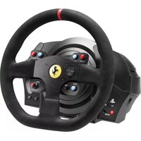
T248X - Joystick THRUSTMASTER - Free user manual and instructions
Find the device manual for free T248X THRUSTMASTER in PDF.



| Product type | Force feedback racing wheel and T3PM pedal set |
| Brand and model | Thrustmaster T248X |
| Power supply | Power adapter 100-240 V, 50-60 Hz; output 18.5 V DC, 2.6 A |
| Rotation angle | 270°, 360°, 540°, 720°, 900° or automatic |
| Force feedback | Yes, with 3 FFB profiles (linear, boosted) |
| Integrated display | T-RDD (Thrustmaster Race Dash Display) for telemetry (PC compatible only) |
| Connectivity | USB-C (wheel) to USB-A (console/PC); RJ12 connector for pedal set; mini-DIN for accessories |
| Shift paddles | 2 magnetic paddles (up/down) |
| Buttons and controls | Directional buttons, MODE, DISPLAY, MENU, VIEW, Xbox, rotary encoder with push |
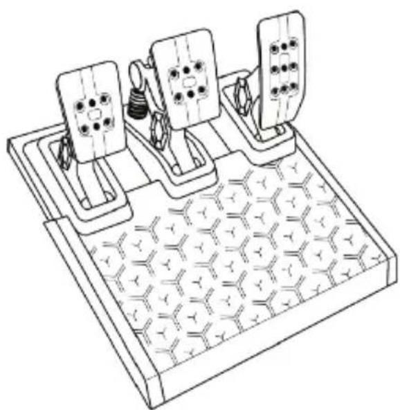
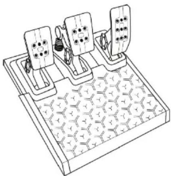
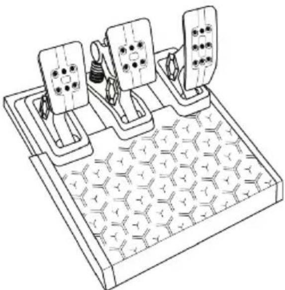
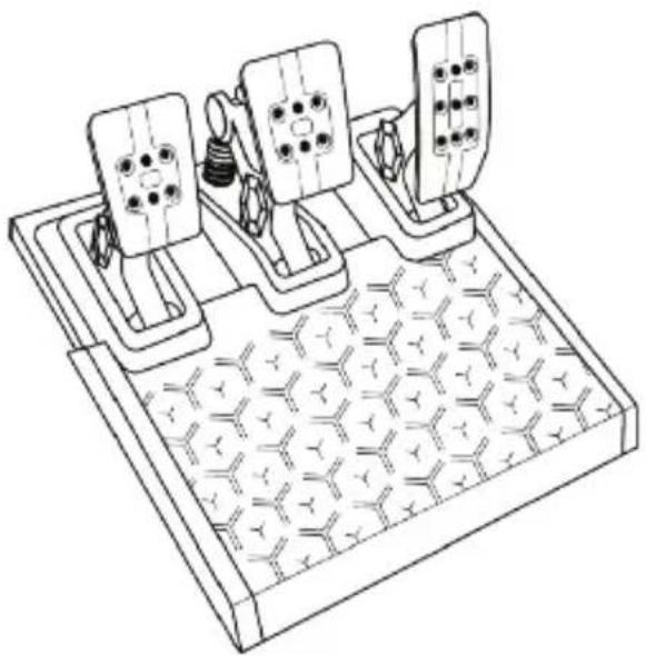
| Pedal set | T3PM: 3 pedals (accelerator, brake, clutch) with height, spacing and tilt adjustments |
| Additional brake spring | Yes, included kit allowing 4 configurations (soft, medium, hard, extra-hard) |
| Compatibility | Xbox One, Xbox Series X|S, PC (Windows 10/11) |
| Mounting | On table/desk (clamping system + metal screw) or on cockpit (M6 screws not included) |
| Maintenance | Clean with a soft, dry cloth; do not use solvents |
| Safety | Do not open the device; play with shoes; avoid prolonged repetitive movements |
| Warranty | 2 years (EU) from delivery; legal conformity warranty |
| Spare parts and repairability | Brake spring kit included; other parts not provided; repair by manufacturer only |
| Dimensions (base) | Approximately 30 x 25 x 20 cm (estimate) |
| Weight (wheel + pedal set) | Approximately 5 kg (estimate) |
Frequently Asked Questions - T248X THRUSTMASTER
User questions about T248X THRUSTMASTER
0 question about this device. Answer the ones you know or ask your own.
Ask a new question about this device
Download the instructions for your Joystick in PDF format for free! Find your manual T248X - THRUSTMASTER and take your electronic device back in hand. On this page are published all the documents necessary for the use of your device. T248X by THRUSTMASTER.
USER MANUAL T248X THRUSTMASTER

WARNING:
To ensure that your T248 racing wheel functions correctly with Xbox One, Xbox Series X|S and PC games, you may be required to install the game's automatic updates (available when your console or PC is connected to the Internet).
TECHNICAL FEATURES

1 T248 base 2 Wheel rim 3 T-RDD (Thrustmaster Race Dash Display) screen 4 Encoder selector switch and encoder push function 5 + and - encoder selector switch 6 2 magnetic paddle shifters (Up and Down) 7 Directional buttons 8 VIEW button on Xbox consoles 9 MODE button
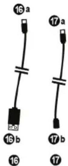
10 Xbox button 11 DISPLAY button 12 MENU button on Xbox consoles 13 Attachment system 14 Metal fastening screw 15 Power cable (EU/US or UK...) (15a) and power adapter (15b) 16 USB-C (16a) - USB-A (16b) cable 17 Quick release USB-C cable – male (17a) to female (17b))

18 Large threaded hole (for attachment system and fastening screw) 19 Threaded holes for attachment to a racing cockpit (not included) 20 Hook-and-loop fastener cable holder 21 Power adapter connector
22 Racing wheel's USB-C connector 23 Mini-DIN connector for Thrustmaster shifter, handbrake or hub (sold separately) 24 RJ12 connector for pedal set
WARNING
Before using this product, please read this manual carefully and save it for later reference.

Warning – Electrical shock
* Keep the product in a dry location and do not expose it to dust or sunlight. * Do not twist or pull on the connectors and cables. * Do not spill any liquid on the product or its connectors. * Do not short-circuit the product. * Never dismantle the product; do not throw it onto a fire and do not expose it to high temperatures. * Do not use a power supply cable other than the one provided with your racing wheel. * Do not use the power supply cable if the cable or its connectors are damaged, split or broken. * Make sure that the power supply cable is properly plugged into an electrical outlet, and properly connected to the connector at the rear of the racing wheel's base. * Do not open up the racing wheel: there are no user-serviceable parts inside. Any repairs must be carried out by the manufacturer, its authorized representative or a qualified technician. * Only use attachment systems/accessories specified by the manufacturer. * If the racing wheel is operating abnormally (if it is emitting any abnormal sounds, heat or odors), stop using it immediately, unplug the power supply cable from the electrical outlet and disconnect the other cables. * If you will not be using the racing wheel for an extended period of time, unplug its power supply cable from the electrical outlet. * The electrical outlet must be located near the equipment and must be easily accessible.

Use only the power supply listed in the user instructions.
Information for power supply adapter
| Information published | Value | Unit |
| Manufacturer's name or trademark, commercial registration number and address | GUILLEMOT CORPORATION S.A.414 196 758 RennesPlace du GranierBP 9714335571 Chantepie CedexFrance | |
| Model identifier | A481-1852590D | |
| Input voltage | 100 - 240 | V |
| Input AC frequency | 50 - 60 | Hz |
| Output voltage | 18.5 | V DC |
| Output current | 2.6 | A |
| Output power | 47.9 | W |
| Average active efficiency | 87.8 | % |
| Efficiency at low load (10%) | 87.8 | % |
| No-load power consumption | 0.10 | W |

Air vents
Make sure not to block any of the air vents on the racing wheel's base. For optimal ventilation, make sure to do the following:
* Position the wheel's base at least 10 cm away from any wall surfaces. * Do not place the base in any tight spaces. * Do not cover the base. * Do not let any dust build up on the air vents.

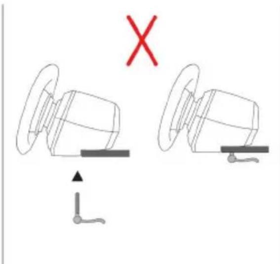
For safety reasons, never use the pedal set with bare feet or while wearing only socks on your feet.
THRUSTMASTER® DISCLAIMS ALL RESPONSIBILITY IN THE EVENT OF INJURY RESULTING FROM USE OF THE PEDAL SET WITHOUT SHOES.

Warning – Injuries due to Force Feedback and repeated movements
Playing with a Force Feedback racing wheel may cause muscle or joint pain. To avoid any problems:
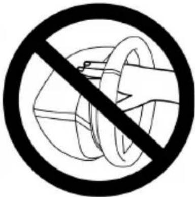
* Avoid lengthy gaming periods. * Take 10 to 15-minute breaks after each hour of play. * If you feel any fatigue or pain in your hands, wrists, arms, feet or legs, stop playing and rest for a few hours before you start playing again. * If the symptoms or pain indicated persist when you start playing again, stop playing and consult your doctor. * Keep out of children's reach. * During gameplay, always leave both hands correctly positioned on the wheel without completely letting go. * During gameplay, never place your hands or your fingers under the pedals or anywhere near the pedal set. * During calibration and gameplay, never place your hand or your arm through the openings in the racing wheel. * Make sure that the racing wheel's base is properly secured, as per this manual's instructions.

Product to be handled only by users 14 years of age or older
HEAVY PRODUCT
Be careful not to drop the product on yourself or on anyone else!
ALWAYS NEVER NEVER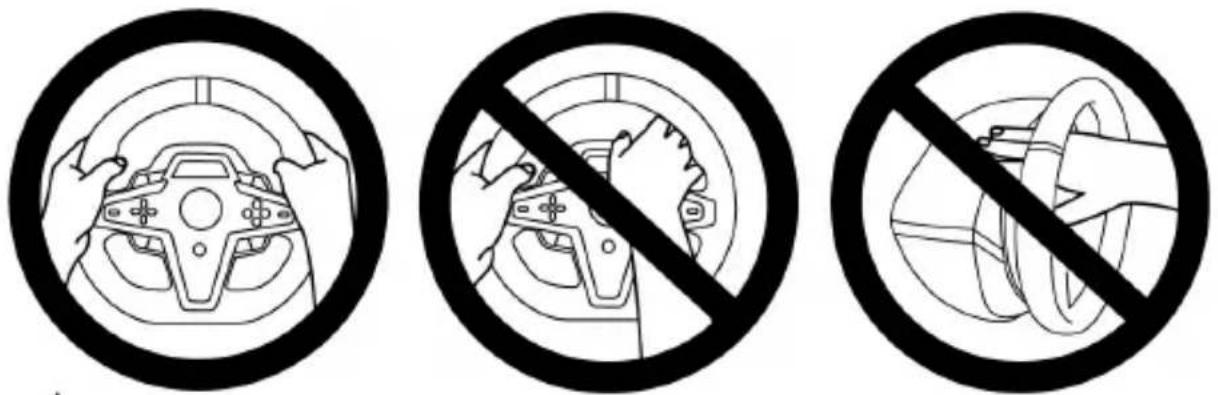
Warning – Pedal set pinch hazard when playing
* Keep the pedal set out of children's reach. * During gameplay, never place your fingers on or anywhere near the sides of the pedals. * During gameplay, never place your fingers on or anywhere near the pedal's rear base. * During gameplay, never place your fingers on or anywhere near the pedal's front base.
NEVER NEVER NEVER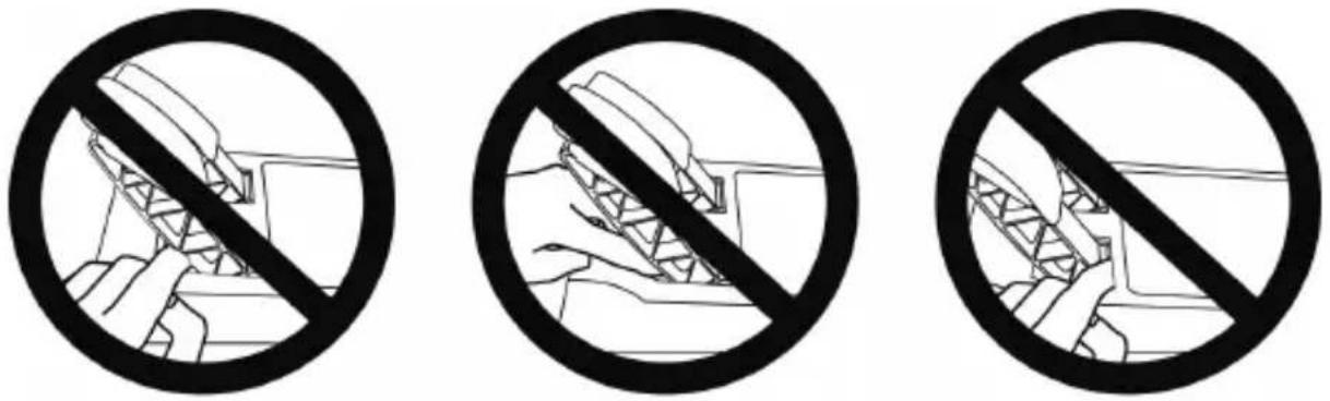
Warning – Pedal set pinch hazard when not playing
* Store the pedal set in a safe place, and keep it out of children's reach.
ATTACHING THE RACING WHEEL
Attaching the racing wheel to a table or a desktop
Start by connecting on the underside of the wheel:
- the power adapter (21);
- the quick release USB-C cable (17a) to the USB-C connector (22);
- the T3PM pedal set (24).
Make sure to follow the paths for the different cables, and attach the cables using the hook-and-loop fastener cable holder (20).

- Place the racing wheel on a table or any other horizontal, flat and stable surface.
- Insert the fastening screw (14) in the attachment system (13), then tighten the device by turning the screw counterclockwise, so that it feeds into the large threaded hole (18) located beneath the racing wheel, until the wheel is perfectly stable.


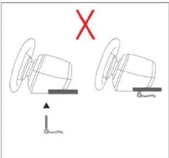
WARNING: Never tighten the screw alone without the attachment system in place! This could damage the racing wheel.
| ATTACHMENT / REMOVAL | DIRECTION |
| To tighten:Turn the screw counterclockwise |   |
| To release:Turn the screw clockwise |  |
Attaching the racing wheel to a racing cockpit (not included)
- Place the base of the racing wheel on the cockpit's shelf.
- Screw two M6 screws (not included) into the cockpit's shelf and into the two threaded holes on the underside of the racing wheel (19).
Important
The length of the two M6 screws must not exceed the thickness of the shelf by more than 0.47 inches/12 mm; longer screws could cause damage to internal components located in the racing wheel's base.
- If necessary, you can also screw the standard attachment system (13, 14) into the large threaded hole (18).
The T248 racing wheel's setup diagrams for cockpits and other supports are available at https://support.thrustmaster.com: click Racing Wheels / T248, and then Template - Cockpit Setup.
INSTALLATION
AUTOMATIC RACING WHEEL AND PEDAL SET CALIBRATION
The wheel automatically self-calibrates when you plug the racing wheel into an electrical outlet and connect the racing wheel's USB connector to the Xbox console or to the PC.
During this phase, the racing wheel will rotate quickly towards the left and the right, covering a 900-degree angle, before stopping at the center.

WARNING:
Never touch the racing wheel during the self-calibration phase! This could result in improper calibration and/or personal injuries.
Never connect the pedal set to the racing wheel's base (or disconnect it from the base) when it is connected to the system or during gameplay (this could result in improper calibration).
Always connect the pedal set before connecting the racing wheel to the system.
Once the racing wheel's calibration is complete and the game has been started, the pedals are automatically calibrated after a few presses.

WARNING:
Never press the pedals during the racing wheel's self-calibration phase or while a game is loading!
This could result in improper calibration.
If your racing wheel and/or pedal set do not function correctly, or if they seem to be improperly calibrated:
Power off your console or PC and completely disconnect the racing wheel. Then reconnect all cables (including the power supply cable and the pedal set), and restart your console (or PC) and your game.
INSTALLATION ON XBOX CONSOLES
- Connect the T3PM pedal set to the RJ12 connector (24) of the base.
- Plug the power cable and power adapter into an electrical outlet.
- Connect the USB-C cable (17) to the USB-C port (22) of the base.
- Connect the USB-C/USB-A cable (16) to the USB-C cable (17) and to a USB-A port on the Xbox console. Once the console is powered on, your racing wheel will self-calibrate automatically.
![graph TD A["Power Supply"] --> B["Switch"] B --> C["Coiled Cable"] C --> D["Device 17"] C --> E["Device 16"] D --> F["Terminal Block 17"] E --> G["Terminal Block 16"] F --> H["Terminal Block 17"] G --> I["Terminal Block 16"] style A fill:#f9f,stroke:#333 style D fill:#ccf,stroke:#333 style F fill:#c…](/content/2026/05/1099726/images/04dc50ea30ae012f745cc28b7ce2ee334f9f36926d96f9e517dd86a75793f6fc.jpg)
You are now ready to play!
Please note:
- The list of games compatible with the Xbox console and the T248 racing wheel is available here: https://support.thrustmaster.com (in the Racing Wheels / T248 / Games Settings section). This list is updated regularly.
INSTALLATION ON PC
- Visit https://support.thrustmaster.com to download the drivers and Force Feedback software for PC. Click Racing Wheels / T248 / Drivers.
- Connect the T3PM pedal set to the RJ12 connector (24) of the base.
- Plug the power cable and power adapter into an electrical outlet.
- Connect the USB-C cable (17) to the USB-C port (22) of the base.
- Connect the USB-C/USB-A cable (16) to the USB-C cable (17) and to a USB-A port on your PC.
![graph TD A["Power Input"] --> B["Switch"] B --> C["Analog Circuit"] C --> D["Computer Interface"] D --> E["Display/USB Icon"] C --> F["Component 16"] C --> G["Component 17"] style A fill:#f9f,stroke:#333 style D fill:#ccf,stroke:#333](/content/2026/05/1099726/images/223821cfd9423c555e0aad0de9384b57d8ad8c111f5b75c721dd4549eb8e121f.jpg)
You are now ready to play!
Please note:
- In the Control Panel and in games, the racing wheel is recognized under the name Thrustmaster Advanced Racer.
UPDATING THE RACING WHEEL'S FIRMWARE
Visit https://support.thrustmaster.com.
Click Racing Wheels / T248 / Firmware, and follow the instructions.
MAPPING FOR XBOX CONSOLES
Please note:
- The screen displaying telemetry information (T-RDD) is currently not compatible on Xbox consoles. It is only compatible on PC.
- Some features (encoders, number of action buttons) are limited by the console protocol.
- On Xbox, the LSB and RSB buttons on the racing wheel are only functional in some upcoming games. The list of games with this feature is updated regularly.
MAPPING FOR PC

| E1P=11↓ | E2P=12↓ | E3P=24↓ | E4P=25↓ |
| E1+=14↑ | E2+=17↑ | E3+=19↑ | E4+=21↑ |
| E1-=15↓ | E2-=16↓ | E3-=18↓ | E4-=20↓ |
USING THE E1 / E2 / E3 / E4 ENCODERS
You can select the active encoder by pushing the encoder selector switch (4) up. The active encoder is displayed on the screen: E1, E2, E3, E4 in succession, and then E1... and so on again.
When the encoder (E1, E2, E3 or E4) is selected, the associated functions are as follows:
- Push (P) by pressing the encoder selector switch (4) downward.
- by pressing the encoder selector switch on the right-hand side (5) upward.
- by pressing the encoder selector switch on the right-hand side (5) downward.
The corresponding action is displayed on the screen.
Please note:
- The E1, E2, E3, and E4 encoders function in most games.
- The screen displaying telemetry information functions in games compatible with the Thrustmaster SDK. The list of compatible games is available here: https://support.thrustmaster.com (in the Racing Wheels / T248 / Games Settings section). This list is updated regularly.
MODE BUTTON
DISPLAYING INFORMATION ON THE RACING WHEEL, AND CONFIGURING THE RACING WHEEL AND PEDAL SET
Press the MODE button (9) to enter the MODE menu.
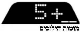
Only the first two segments are displayed when you are in this menu.
ABOUT
Use the directional buttons (7) in this menu as follows:
| Navigation | Screen | Information / Options | |
| 8 levels |  2 options 2 options | XBOX/PCSelect your system:Xbox console or PC | - Selection of Xbox console (by default)- Selection of PC systemNote: To validate your system choice, press the MODE button (9). Selection will be saved when EXIT appears on screen. |
 3 displays 3 displays | ABOUTGeneral information | - Firmware version of racing wheel base- Name of device connected to mini-DIN connector (23)- Type of pedal set connected to RJ12 connector (24) | |
 3 options 3 options | FFBSelect the Force Feedback profile(see FFB PROFILE DIAGRAM section) | - FFB 1- FFB 2 (by default)- FFB 3 | |
 6 options 6 options | FORCESelect the overall wheel's force effect level | ||
 6 options 6 options | ROT°Select the angle of rotation(only for games in which the angle of rotation is not automatic) | - 270°- 360°- 540°- 720°- 900°- AUTO = Automatic (by default) | |
 2 options 2 options | PEDALSelect the pedal set configuration | - FLOOR: floor position (by default)- INV.: suspended position(the accelerator and clutch pedals are reversed) | |
| 1 display | TEMPMotor temperature | Racing wheel's motor temperature displayed in real time | |
 1 option 1 option | RESETReset the racing wheel to default mode. | - N: No- Y: YesSelect Y, then press the MODE button (9). The racing wheel is reset when EXIT appears on screen. | |
FORCE
Allows to adjust in real time (= directly in race) all the racing wheel's force effects, from 20 to 100%.

FFB (FFB 1 / FFB 2 / FFB 3) PROFILE DIAGRAM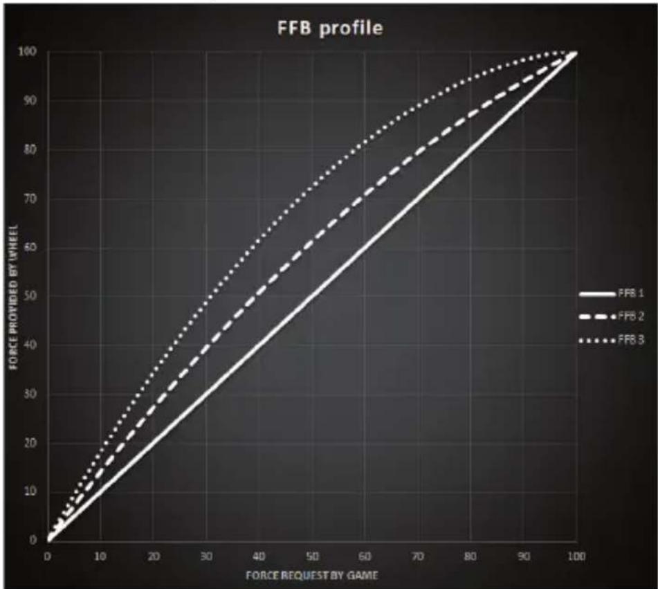
FFB 1
The FFB 1 effect provides linear Force Feedback. The force that you feel is 100% proportional to the force requested by the game.
FFB 2 and FFB 3
The FFB 2 and FFB 3 effects boost the Force Feedback in order to accentuate the force that you feel in relation to the force requested by the game.
Please note:
- Validate your choices by pressing the MODE button (9): EXIT is displayed before returning to your default screen.
- The directional buttons (7) are disabled in games and in the console's interface when the MODE button is enabled.
DISPLAY BUTTON
CONFIGURING THE DISPLAY OF TELEMETRY SETTINGS
(in games for PC compatible with the display)
Please note:
- The list of games for PC compatible with the T-RDD (Thrustmaster Race Dash Display) screen is available here: https://support.thrustmaster.com (in the Racing Wheels / T248 / Games Settings section). This list is updated regularly.
- The DISPLAY button only works in these games.
- The DISPLAY button is currently not compatible on Xbox consoles.
Press the DISPLAY button (11) to enter the DISPLAY menu.
Only the last two segments are displayed when you are in this menu.

Use the directional buttons (7) in this menu as follows:
| Navigation | Screen | Information / Options | |
  5 levels 5 levels | No |  Shifter Shifter | |
| No | SPEED Speed Speed | ||
  5 options for display across the segments 5 options for display across the segments | RPM RPM and choice of view across the 9 segments RPM and choice of view across the 9 segments | - REV >>: left to right- REV <<: right to left- REV ><: outside toward center- REV <>: center toward outside- REV --: no display on the segments | |
  2 options 2 options | POS Position Position | - DRI: position in the race- LAP: number of laps | |
  3 options 3 options | TIME Time Time | - PBL: best personal lap time- CL: current lap time- LL: last lap time | |
Please note:
- Validate your choices by pressing the DISPLAY button (11).
- The directional buttons (7) are disabled in games and in the console's interface when the DISPLAY button is enabled.
VARIOUS TIPS AND FAQs
Visit https://support.thrustmaster.com. Click Racing Wheels / T248, and then Manual or FAQ.
T3PM PEDAL SET

TECHNICAL FEATURES
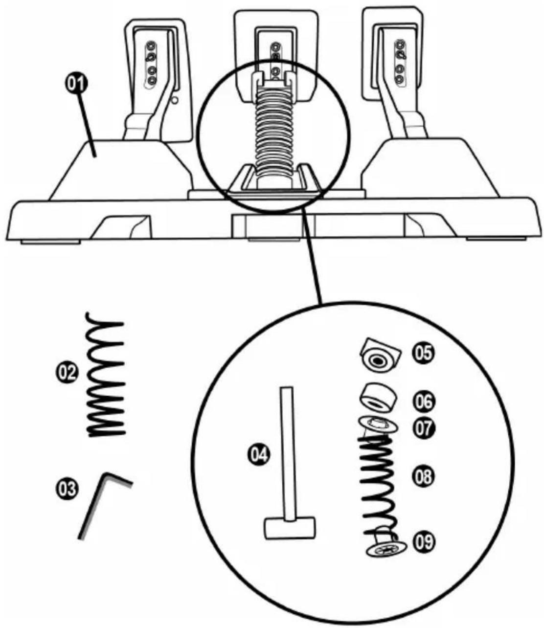
1 Pedal set 2 Additional hard spring (black) 3 2.5 mm Allen key 4 Spring retaining rod 5 Upper retaining head with washer
6 Elastomer cushioning ring (white – Shore 70) 7 Upper plastic spacer (red) 8 Soft spring (silver – installed by default) 9 Lower plastic spacer (red)
WARNING
Before using this product, please read this manual carefully and save it for later reference.

For safety reasons, never use the pedal set with bare feet
or while wearing only socks on your feet.
THRUSTMASTER® DISCLAIMS ALL RESPONSIBILITY IN THE EVENT OF INJURY RESULTING
FROM USE OF THE PEDAL SET WITHOUT SHOES.

Warning – Pedal set pinch hazard when playing
* Keep the pedal set out of children's reach. * During gameplay, never place your fingers on or anywhere near the sides of the pedals. * During gameplay, never place your fingers on or anywhere near the pedal's rear base. * During gameplay, never place your fingers on or anywhere near the pedal's front base.


AUTOMATIC CALIBRATION OF THE PEDAL SET

IMPORTANT
- Never connect the pedal set to the racing wheel's base (or disconnect it from the base) when it is connected to the Xbox console, or during gameplay (this could result in improper calibration).
- Always connect the pedal set before connecting the racing wheel to the console or to the PC.
- Once the racing wheel's calibration is complete and the game has been started, the pedals are automatically calibrated after a few presses.
- Never press the pedals during the racing wheel's self-calibration phase or while a game is loading! This could result in improper calibration.
If your racing wheel and/or pedal set do not function correctly, or if they seem to be improperly calibrated:
Power off your console and completely disconnect the racing wheel. Then reconnect all cables (including the power supply cable and the pedal set), and restart your console and your game.
ATTACHING THE PEDAL SET TO A SUPPORT OR COCKPIT
The pedal set can be attached to a variety of different compatible supports (sold separately) using the five M6-type threaded holes located underneath the base. To do so, screw at least two M6 screws (not included) through the support shelf, and into the threaded holes on the underside of the pedal set's base.

Important: the length of the M6 screws must not exceed the thickness of your support by more than 0.47 inches/12 mm, so as not to risk damaging the pedal set's internal components.

The pedal set's setup diagrams for cockpits and other supports are available at https://support.thrustmaster.com: click Racing Wheels / T3PM, and then Template - Cockpit setup.
ADJUSTING THE PEDAL SET
Each of the three pedals includes:
- A pedal arm (10) with two perforations.
- A plastic head support (11) (placed between the head and the arm) with four perforations.
- A metal head (12) with multiple perforations (nine for the accelerator – six for the brake – six for the clutch).

ATTENTION: To avoid any calibration problems, be sure to always disconnect your wheel's USB cable from the console or PC before making any adjustments to your pedal set.
Adjusting the HEIGHT of the gas pedal
- Using the included 2.5 mm Allen key (3), unscrew the two screws holding the metal head (12) and its support (11) in place.
- Select your preferred height position, then replace and re-tighten the screws so that the metal head (12) and its support (11) are held firmly in place.

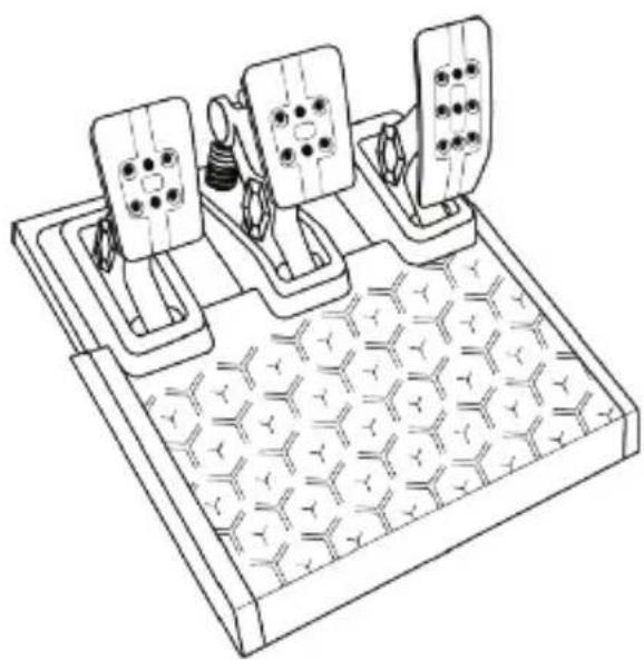
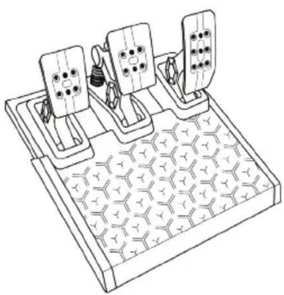
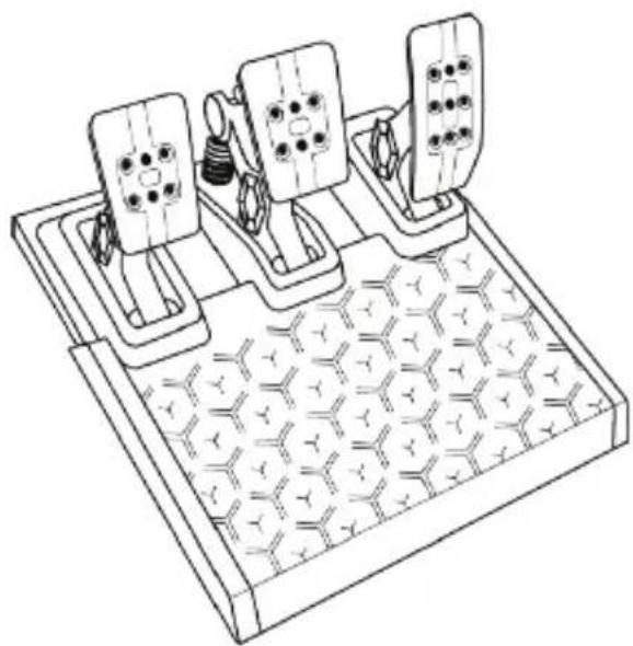
Low position

High position (default)
Adjusting the SPACING of the three pedals
- Using the included 2.5 mm Allen key (3), unscrew the two screws holding the metal head (12) and its support (11) in place.
- Select your preferred position (to the left, centered, or to the right), then replace and re-tighten the screws so that the metal head (12) and its support (11) are held firmly in place.
Examples illustrating the brake pedal:
Number of possible spacing positions per pedal:
- Three for gas pedal
- Three for brake pedal
- Three for clutch pedal
Adjusting the INCLINATION of the pedals
- Using the included 2.5 mm Allen key (3), unscrew the two screws holding the metal head (12) and its support (11) in place.
- Turn the plastic head support (11) 180°, then replace and re-tighten the screws so that the metal head (12) and its support (11) are held firmly in place.
Examples illustrating the gas pedal:
Less inclined position (default)

More inclined position
Number of possible inclination positions per pedal:
- Two for gas pedal
- Two for brake pedal
- Two for clutch pedal
4 possible configurations and settings for the brake pressure force
This mod lets you experience a different feel and resistance when braking.
You can choose to install it or not, according to your preferences.
| Brake resistance Soft | Medium(by default) | Hard Very hard | ||
| Recommended use Desk | Desk | Pedal set support | Cockpit | |
| Soft silver spring (8) | x | x | ||
| White elastomer cushioning ring (6) | x | x | ||
| Hard black spring (2) | x | x | ||
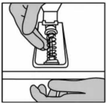
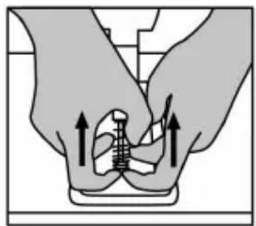
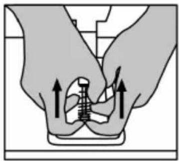
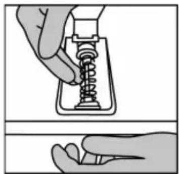
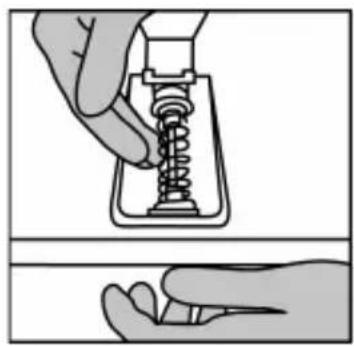
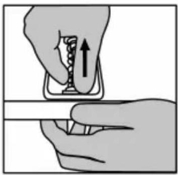
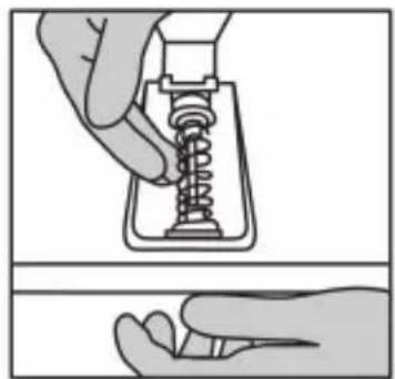
- Pull hard on the lower plastic spacer (9) to compress the spring and remove the spring retaining rod (4) from its location.
Method 1:


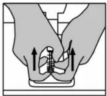
Method 2:


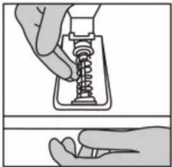
- Reposition the different elements on the spring retaining rod (4). Start with the lower plastic spacer (9), your choice of spring (2) or (8), and then the upper plastic spacer (7).
- After your selected configuration, install the elastomer cushioning ring (6).
- Adjust the upper retaining head with washer (5) and position it in its location.
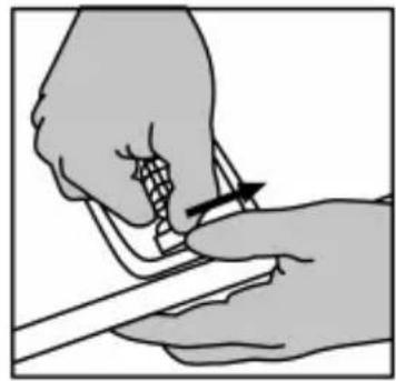
- Strongly compress the spring in order to place the spring retaining rod (4) in its location

A video showing how to change the spring is available at https://support.thrustmaster.com: click Racing Wheels / T3PM.
CONSUMER WARRANTY INFORMATION
Worldwide, Guillemot Corporation S.A., whose registered office is located at Place du Granier, B.P. 97143, 35571 Chantepie, France (hereinafter “Guillemot”) warrants to the consumer that this Thrustmaster product shall be free from defects in materials and workmanship, for a warranty period which corresponds to the time limit to bring an action for conformity with respect to this product. In the countries of the European Union, this corresponds to a period of two (2) years from delivery of the Thrustmaster product. In other countries, the warranty period corresponds to the time limit to bring an action for conformity with respect to the Thrustmaster product according to applicable laws of the country in which the consumer was domiciled on the date of purchase of the Thrustmaster product (if no such action exists in the corresponding country, then the warranty period shall be one (1) year from the original date of purchase of the Thrustmaster product).
Should the product appear to be defective during the warranty period, immediately contact Technical Support, who will indicate the procedure to follow. If the defect is confirmed, the product must be returned to its place of purchase (or any other location indicated by Technical Support).
Within the context of this warranty, the consumer's defective product shall, at Technical Support's option, be either replaced or returned to working order. If, during the warranty period, the Thrustmaster product is subject to such reconditioning, any period of at least seven (7) days during which the product is out of use shall be added to the remaining warranty period (this period runs from the date of the consumer's request for intervention or from the date on which the product in question is made available for reconditioning, if the date on which the product is made available for reconditioning is subsequent to the date of the request for intervention). If permitted under applicable law, the full liability of Guillemot and its subsidiaries (including for consequential damages) is limited to the return to working order or the replacement of the Thrustmaster product. If permitted under applicable law, Guillemot disclaims all warranties of merchantability or fitness for a particular purpose.
This warranty shall not apply: (1) if the product has been modified, opened, altered, or has suffered damage as a result of inappropriate or abusive use, negligence, an accident, normal wear, or any other cause unrelated to a material or manufacturing defect (including, but not limited to, combining the Thrustmaster product with any unsuitable element, including in particular power supplies, rechargeable batteries, chargers, or any other elements not supplied by Guillemot for this product); (2) if the product has been used for any use other than home use, including for professional or commercial purposes (game rooms, training, competitions, for example); (3) in the event of failure to comply with the instructions provided by Technical Support; (4) to software, said software being subject to a specific warranty; (5) to consumables (elements to be replaced over the product's lifespan: disposable batteries, audio headset or headphone ear pads, for example); (6) to accessories (cables, cases, pouches, bags, wrist-straps, for example); (7) if the product was sold at public auction.
This warranty is nontransferable.
The consumer's legal rights with respect to laws applicable to the sale of consumer goods in his or her country are not affected by this warranty.
Additional warranty provisions
During the warranty period, Guillemot shall not provide, in principle, any spare parts, as Technical Support is the only party authorized to open and/or recondition any Thrustmaster product (with the exception of any reconditioning procedures which Technical Support may request that the consumer carry out, by way of written instructions – for example, due to the simplicity and the lack of confidentiality of the reconditioning process – and by providing the consumer with the required spare part(s), where applicable).
Given its innovation cycles and in order to protect its know-how and trade secrets, Guillemot shall not provide, in principle, any reconditioning notification or spare parts for any Thrustmaster product whose warranty period has expired.
In the United States of America and in Canada, this warranty is limited to the product's internal mechanism and external housing. In no event shall Guillemot or its affiliates be held liable to any third party for any consequential or incidental damages resulting from the breach of any express or implied warranties. Some States/Provinces do not allow limitation on how long an implied warranty lasts or exclusion or limitation of liability for consequential or incidental damages, so the above limitations or exclusions may not apply to you. This warranty gives you specific legal rights, and you may also have other rights which vary from State to State or Province to Province.
Liability
If permitted under applicable law, Guillemot Corporation S.A. (hereinafter "Guillemot") and its subsidiaries disclaim all liability for any damages caused by one or more of the following: (1) the product has been modified, opened, or altered; (2) failure to comply with assembly instructions; (3) inappropriate or abusive use, negligence, an accident (an impact, for example); (4) normal wear; (5) the use of the product for any use other than home use, including for professional or commercial purposes (game rooms, training, competitions, for example). If permitted under applicable law, Guillemot and its subsidiaries disclaim all liability for any damages unrelated to a material or manufacturing defect with respect to the product (including, but not limited to, any damages caused directly or indirectly by any software, or by combining the Thrustmaster product with any unsuitable element, including in particular power supplies, rechargeable batteries, chargers, or any other elements not supplied by Guillemot for this product).
DECLARATION OF CONFORMITY
CANADIAN COMPLIANCE NOTICE: this Class B digital apparatus meets all requirements of the Canadian Interference-Causing Equipment Regulations.
USA COMPLIANCE NOTICE: this equipment has been tested and found to comply with the limits for a Class B digital device, pursuant to Part 15 of the FCC rules. Operation is subject to the following two conditions:
(1) This device may not cause harmful interference, and (2) This device must accept any interference received, including interference that may cause undesired operation. These limits are designed to provide reasonable protection against harmful interference in a residential installation. This equipment generates, uses, and can radiate radio frequency energy and, if not installed and used in accordance with the instructions, may cause harmful interference to radio communications. However, there is no guarantee that interference will not occur in a particular installation. If this equipment does cause harmful interference to radio or television reception, which can be determined by turning the equipment off and on, the user is encouraged to try to correct the interference by one or more of the following measures:
- Reorient or relocate the receiving antenna.
- Increase the separation between the equipment and receiver.
- Connect the equipment into an outlet on a circuit different from that to which the receiver is connected.
- Consult the dealer or an experienced radio/TV technician for help.

COPYRIGHT
©2022 Guillemot Corporation S.A. All rights reserved. Thrustmaster® is a registered trademark of Guillemot Corporation S.A. Manufactured and distributed by Guillemot Corporation S.A.
Microsoft, Xbox, Xbox "Sphere" Design, Xbox Series X|S, Xbox One, and Windows 10/11 are trademarks of the Microsoft group of companies.
All other trademarks and brand names are hereby acknowledged and are the property of their respective owners. Contents, design, and specifications are subject to changes without notice and may vary from one country to another. Photos and illustrations not binding. Designed in North America and Europe, made in China.

WARNING: this product can expose you to chemicals including Bisphenol A (BPA), which is known to the State of California to cause birth defects or other reproductive harm. For more information go to www.P65Warnings.ca.gov
ENVIRONMENTAL PROTECTION RECOMMENDATION

In the European Union, the UK and Turkey: At the end of its working life, this product should not be disposed of with standard household waste, but rather dropped off at a collection point for the disposal of Waste Electrical and Electronic Equipment (WEEE) for recycling.
This is confirmed by the symbol found on the product, user manual or packaging.
Depending on their characteristics, the materials may be recycled. Through recycling and other forms of processing Waste Electrical and Electronic Equipment, you can make a significant contribution towards helping to protect the environment.
Please contact your local authorities for information on the collection point nearest you.
For all other countries: Please adhere to local recycling laws for electrical and electronic equipment.
Retain this information. Colors and decorations may vary.
Plastic fasteners and adhesives should be removed from the product before it is used.
www.thrustmaster.com
*Applicable to EU, UK and Turkey only

T248
FOR XBOX ONE, XBOX SERIES X|S AND PC

WARNING:



FFB CURVES (FFB 1 / FFB 2 / FFB 3)
FFB 1
TECHNICAL SPECIFICATIONS
Low position


Method 2:


CONSUMER WARRANTY INFORMATION
www.thrustmaster.com
T248
FOR XBOX ONE, XBOX SERIES X|S AND PC
User manual


WARNING:

Visit https://support.thrustmaster.com.
FFB PROFILE DIAGRAM (FFB 1 / FFB 2 / FFB 3)
FFB 1
TECHNICAL SPECIFICATIONS

Low position


Method 2:


COPYRIGHT


WARNING:

Visit https://support.thrustmaster.com.
FFB PROFILE DIAGRAM (FFB 1 / FFB 2 / FFB 3)
FFB 1
TECHNICAL SPECIFICATIONS


Method 2:


www.thrustmaster.com

T248
FOR XBOX ONE, XBOX SERIES X|S AND PC
User manual

WARNING:

FFB PROFILE DIAGRAM (FFB 1 / FFB 2 / FFB 3)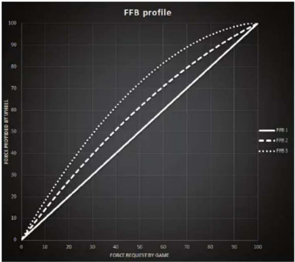
FFB 1
TECHNICAL SPECIFICATIONS
Low position


Method 2:


COPYRIGHT
www.thrustmaster.com

WARNING!

15

16 17


FFB PROFILE DIAGRAM (FFB 1 / FFB 2 / FFB 3)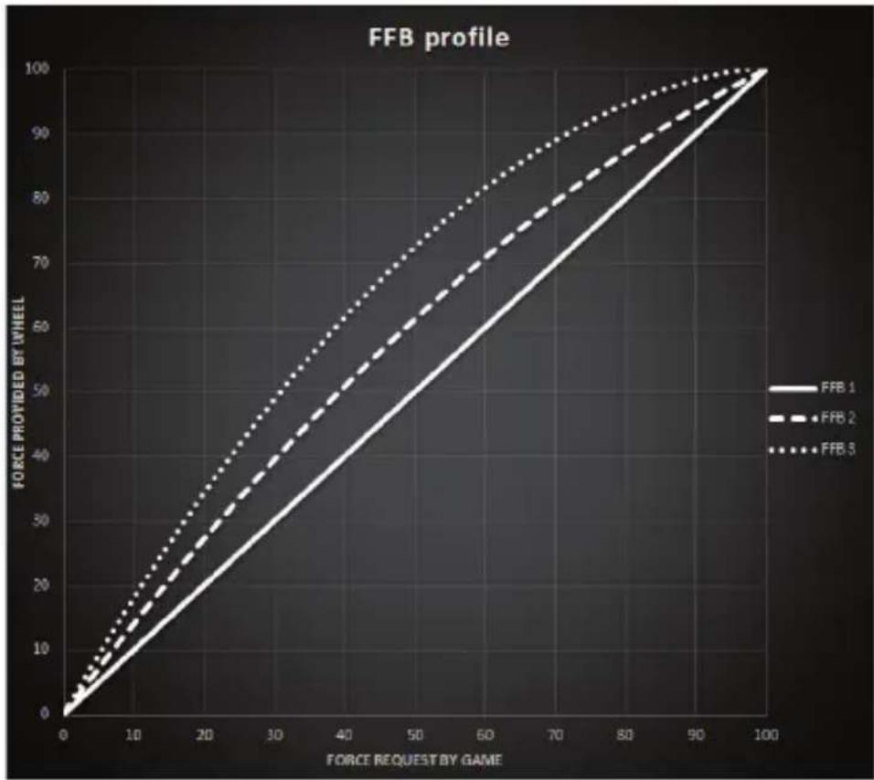
FFB 1
ADJUSTING THE PEDAL SET
Deep position

Right position


Method 2:


www.thrustmaster.com

WARNING:

15

16


FFB PROFILE DIAGRAM (FFB 1 / FFB 2 / FFB 3)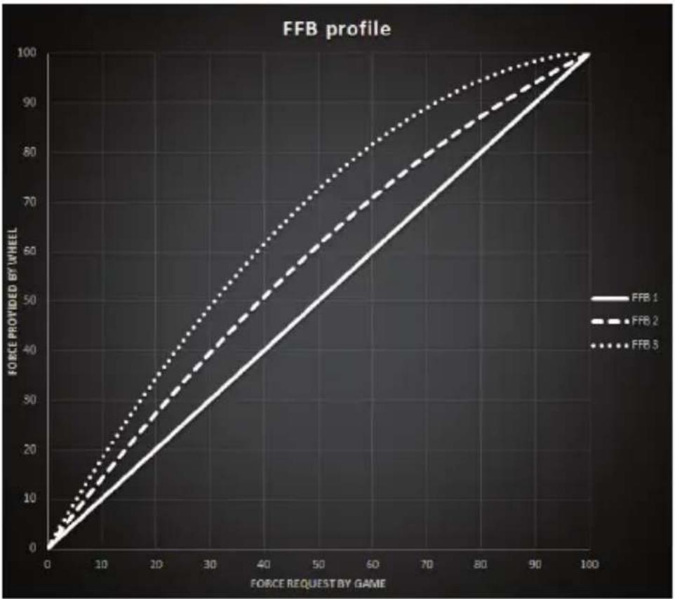
FFB


Method 2:


www.thrustmaster.com
WARNING:

Visit https://support.thrustmaster.com.
FFB PROFILE DIAGRAM (FFB 1 / FFB 2 / FFB 3)
FFB 1
TECHNICAL SPECIFICATIONS

Low position

Right position

Method 2:


https://support.thrustmaster.com

COPYRIGHT
www.thrustmaster.com
WARNING!
1 Pedal block
NEVER
NEVER
Low position


Method 2:


www.thrustmaster.com
EAC
T248
FOR XBOX ONE, XBOX SERIES X|S AND PC
User Manual


WARNING:

Warning – Risk of pinching in the pedal assembly while playing


Visit https://support.thrustmaster.com.
FFB PROFILE DIAGRAM (FFB 1 / FFB 2 / FFB 3)
FFB 1
TECHNICAL SPECIFICATIONS

ATTACHING THE PEDAL SET TO A SUPPORT OR COCKPIT
Low position


Method 2:


COPYRIGHT
www.thrustmaster.com

WARNING:


Visit https://support.thrustmaster.com.
TECHNICAL SPECIFICATIONS


Method 2:


COPYRIGHT
www.thrustmaster.com

WARNING:

15

16


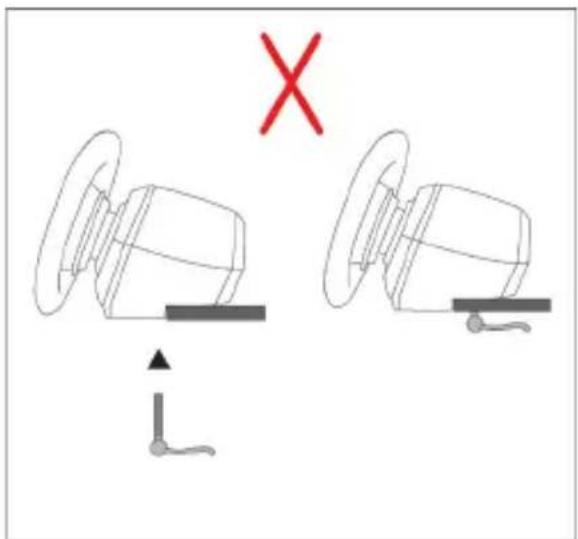
DIAGRAM OF FORCE FEEDBACK PROFILES (FFB 1 / FFB 2 / FFB 3)
COMPONENTS

Low position


Method 2:


https://support.thrustmaster.com

COPYRIGHT
www.thrustmaster.com

WARNING:
https://support.thrustmaster.com/ja/
TECHNICAL SPECIFICATIONS

Never do
Never do


Technical features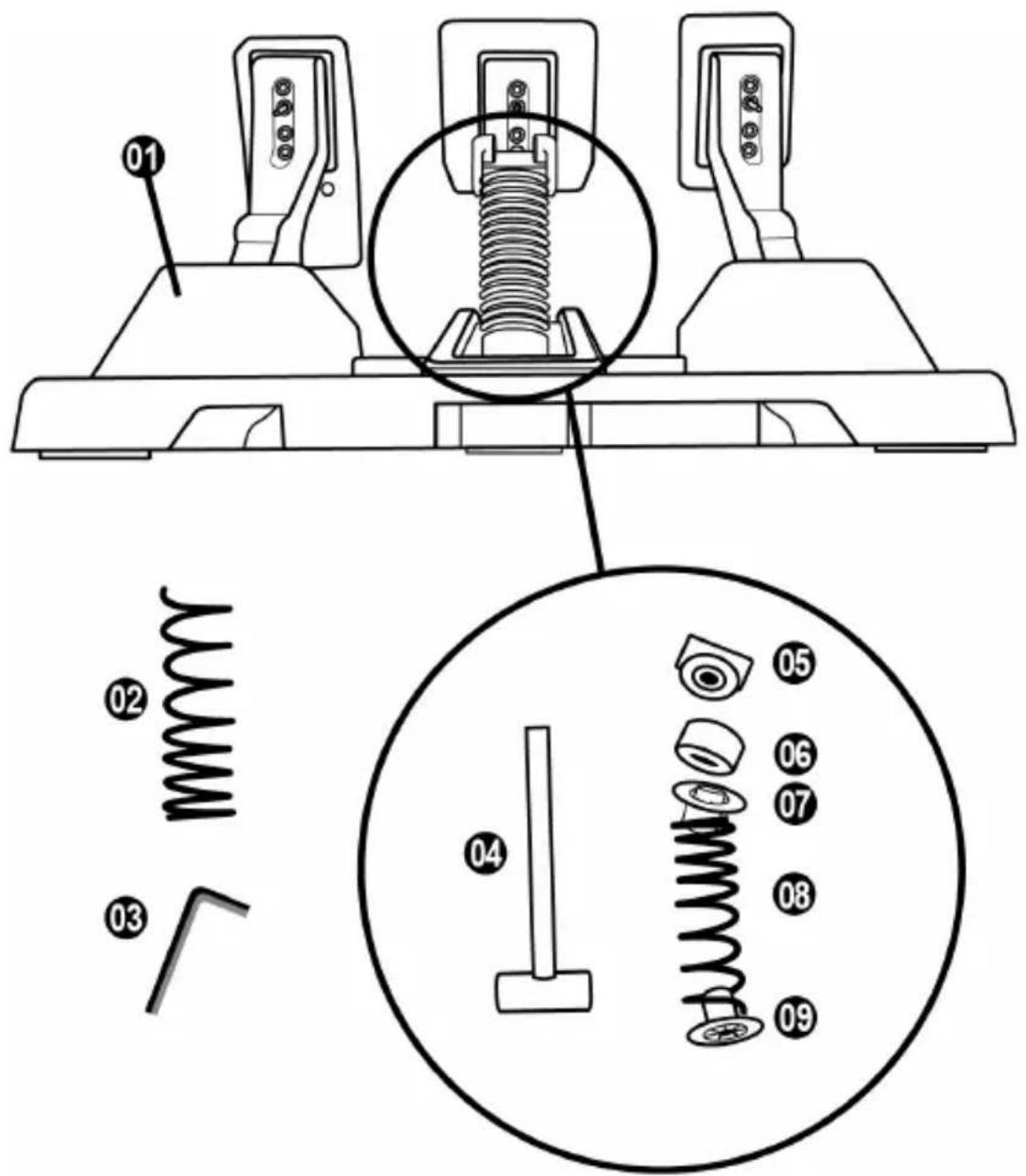
1 Pedal set
2 Additional hard spring (black)
3 2.5 mm Allen key
4 Spring retaining rod
5 Upper retaining head with washer
Never do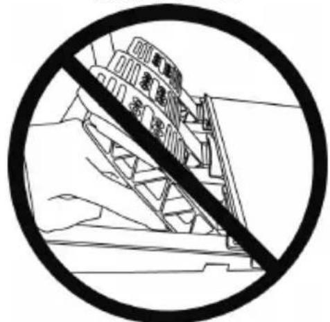
Never do
Automatic calibration of the pedal set

Important
Low position

High position (default)
Adjusting the spacing of the 3 pedals


Method 2:


www.thrustmaster.com
Made in China.

: outer box


T248

Warning:

FFB (FFB 1 / FFB 2 / FFB 3) curve graph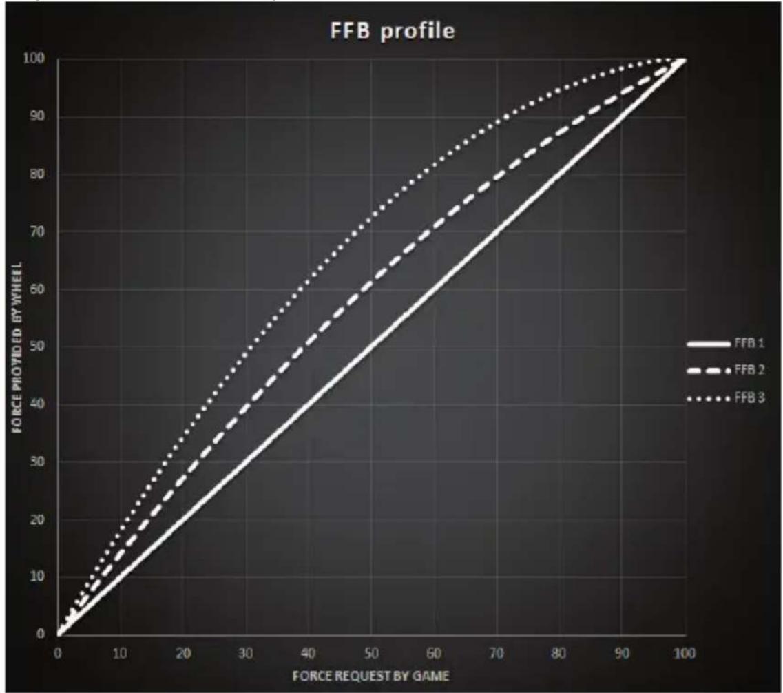
FFB 1
Use the directional pad buttons (7) as follows:
Technical specifications
Low position High position (default)
Adjust the spacing of the three pedals

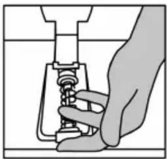
Method 2:


T248
Warning:

WARNING — Risk of pinching with the pedal assembly while playing

WARNING — Risk of pinching with the pedal assembly when not playing

FFB (FFB 1 / FFB 2 / FFB 3) curve diagram
FFB 1
Use the directional buttons (7) as follows:
Technical specifications
Low position High position (default)
Adjust the spacing between the three pedals
Left position Center position (default) Right position
Number of spacing positions available for each pedal:
Lower tilt position (default) Higher tilt position
Number of tilt positions available for each pedal:


Method 2:


WARNING:

NEVER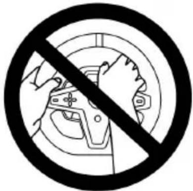
Absolutely forbidden
Absolutely forbidden
Absolutely forbidden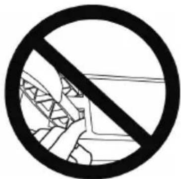

Technical characteristics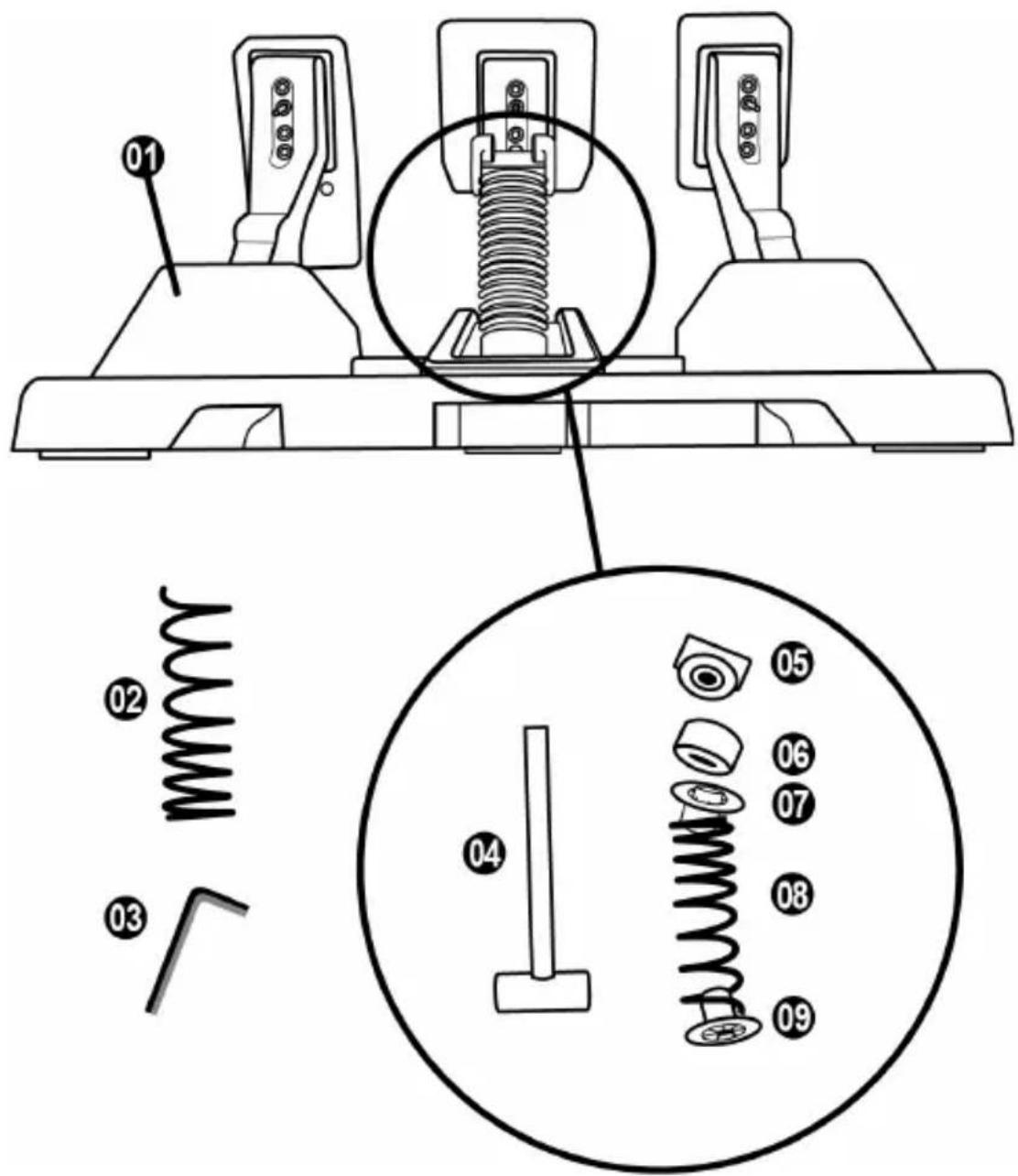
Absolutely forbidden
Absolutely forbidden
Automatic calibration of the pedal set

Important


Method 2:


www.thrustmaster.com


THRUSTMASTER®
Technical support
https://support.thrustmaster.com


T248


15
(Thrustmaster Race Dash Display)
Step 1
Step


Avoid this text
Avoid this text
: https://support.thrustmaster.com https://support.thrustmaster.com : https://support.thrustmaster.com Template - Cockpit setup, T3PM / (Racing Wheels) Racing Wheels above
Adjusting the DDS settings
Position to the right

Position to the left
Position more tilted


Method 2:


Racing Wheels : https://support.thrustmaster.com .T3PM / (Mounting Wheels)
https://support.thrustmaster.com

Copyright
www.thrustmaster.com

WARNING:

FFB CURVE (FFB 1 / FFB 2 / FFB 3)
FFB 1
VARIOUS TIPS, QUESTIONS AND ANSWERS
TECHNICAL PARTS

MOUNT THE PEDAL SET ON A SUPPORT OR A COCKPIT
Low position High position (standard)
Adjust the SPACE between the three pedals
Left position Central position (standard) Right position
Less tilted position (standard)

More tilted position

Method 2:


COPYRIGHT PROTECTED
www.thrustmaster.com
WARNING:

FFB PROFILE DIAGRAM (FFB 1 / FFB 2 / FFB 3)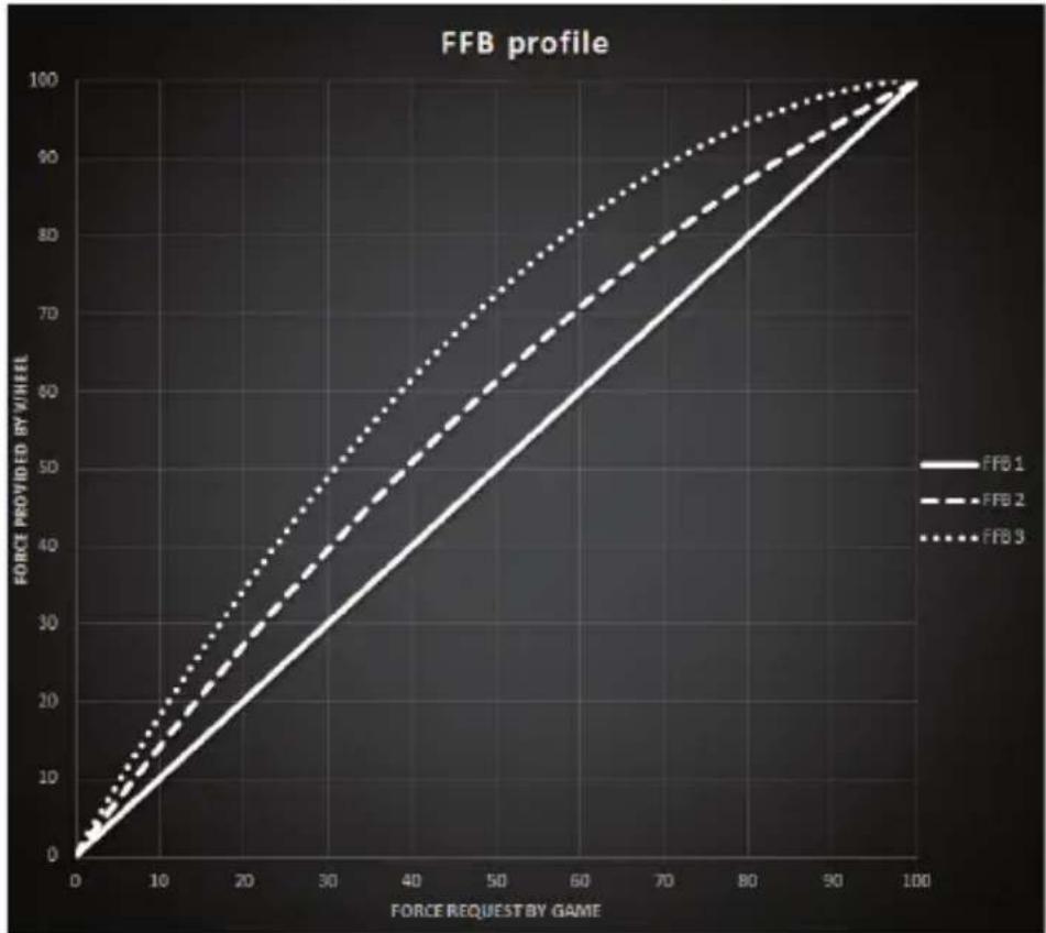
FFB 1
TECHNICAL SPECIFICATIONS
Low position High position (default)
Left position


Method 2:


https://support.thrustmaster.com



COPYRIGHT
www.thrustmaster.com
WARNING:

15

16 17
1 T248 base 2 Steering wheel 3 T-RDD (Thrustmaster Race Dash Display) screen 4 Encoder switch and encoder press function 5 Encoder switch + and - 6 2 magnetic paddle shifters (Up and Down) 7 Directional buttons 8 VIEW button on Xbox consoles 9 MODE button


Warning - Risk of pinching in the pedal while playing

Now you can play!
FFB PROFILE DIAGRAM (FFB 1 / FFB 2 / FFB 3)
TECHNICAL SPECIFICATIONS

Left position

Center position (default)

Right position


Method 2:


https://support.thrustmaster.com

COPYRIGHT
www.thrustmaster.com
WARNING:


FFB PROFILE DIAGRAM (FFB 1 / FFB 2 / FFB 3)
FFB 1

Low position

Tilts more


Method 2:


Copyright
www.thrustmaster.com
:7771N
(Thrustmaster Race Dash Display)
4
7
Xbox View 8
MODE 9

USB-C 22 Mini-DIN 23 Thrustmaster 24
18 (All) 19 20 21
.


https://support.thrustmaster.com
(All) / T248 Drivers / (All) Racing Wheels
.Thrustmaster Advanced Racer
https://support.thrustmaster.com
Racing Wheels https://support.thrustmaster.com:
(FFB 1 / FFB 2 / FFB 3) FFB 77
FFB 1
100%
FFB 3 -1 FFB 2
Thrustmaster Race Dash Display (T-RDD)
Games / T248 / Racing Wheels https://support.thrustmaster.com
| הכלה /הכלה | הכלה | הכלה | |
 | הכלה | ↑↓5 | |
 | הכלה | ||
| הכלה :<< REV- >> REV- >> REV- >> REV- >> REV- >> REV- >> REV- >> REV- >> REV- >> REV- >> REV- >> REV- >> REV- >> REV- >> REV- >> REV- >> REV- >> REV- >> REV- >> REV- >> REV- >> REV- >> REV- >> REV- >> REV- >> REV- >> REV- >> REV- >> REV- >> REV- >> REV- >> REV- >> REV- >> REV- >>REV- >> REV- >> REV- >> REV- >> REV- >> REV- >> REV- >> REV- >> REV- >> REV- >> REV- >> REV- >> REV- >> REV- >> REV- >> REV- >> REV- >> REV- >> REV- >> REV- >> REV- >> REV- >> REV- >> REV- >> REV- >> REV- >> REV- >> REV- >> REV- >> REV- >> REV- >> REV- >> REV- >> REV - >> REV- >> REV- >> REV- >> REV- >> REV- >> REV- >> REV- >> REV- >> REV- >> REV- >> REV- >> REV- >> REV- >> REV- >> REV- >> REV- >> REV- >> REV- >> REV- >> REV- >> REV- >> REV- >> REV- >> REV- >> REV- >> REV- >> REV- >> REV- >> REV- >> REV- >> REV- >> REV- >> REV- > >> REV- >> REV- >> REV- >> REV- >> REV- >> REV- >> REV- >> REV- >> REV- >> REV- >> REV- >> REV- >> REV- >> REV- >> REV- >> REV- >> REV- >> REV- >> REV- >> REV- >> REV- >> REV- >> REV- >> REV- >> REV- >> REV- >> REV- >> REV- >> REV- >> REV- >> REV- >> REV- >> REV->> >> REV- >> REV- >> REV- >> REV- >> REV- >> REV- >> REV- >> REV- >> REV- >> REV- >> REV- >> REV- >> REV- >> REV- >> REV- >> REV- >> REV- >> REV- >> REV- >> REV- >> REV- >> REV- >> REV- >> REV- >> REV- >> REV- >> REV- >> REV- >> REV- >> REV- >> REV- >> REV- >> REV- — REV- >> REV- >> REV- >> REV- >> REV- >> REV- >> REV- >> REV- >> REV- >> REV- >> REV- >> REV- >> REV- >> REV- >> REV- >> REV- >> REV- >> REV- >> REV- >> REV- >> REV- >> REV- >> REV- >> REV- >> REV- >> REV- >> REV- >> REV- >> REV- >> REV- >> REV- >> REV- >> REV- >>Rev- >> REV- >> REV- >> REV- >> REV- >> REV- >> REV- >> REV- >> REV- >> REV- >> REV- >> REV- >> REV- >> REV- >> REV- >> REV- >> REV- >> REV- >> REV- >> REV- >> REV- >> REV- >> REV- >> REV- >> REV- >> REV- >> REV- >> REV- >> REV- >> REV- >> REV- >> REV- >> REV- >> REV | RPM | ↔ ↔ ↔ ↔ ↔ ↔ ↔ ↔ ↔ ↔ ↔ ↔ ↔ ↔ ↔ ↔ ↔ ↔ ↔ ↔ ↔ ↔ ↔ ↔ ↔ ↔ ↔ ↔ ↔ ↔ ↔ ↔ ↔ ↔ ↔ ↔ ↔ ↔ ↔ ↔ ↔ ↔ ↔ ↔ ↔ ↔ ↔ ↔ ↔ ↔ ↔ ↔ ↔ ↔ ↔ ↔ ↔ ↔ ↔ ↔ ↔ ↔ ↔ ↔ ↔ ↔ ↔ ↔ ↔ ↔ ↔ ↔ ↔ ↔ ↔ ↔ ↔ ↔ ↔ ↔ ↔ ↔ ↔ ↔ ↔ ↔ ↔ ↔ ↔ ↔ ↔ ↔ ↔ ↔ ↔ ↔ ↔ ↔ ↔ ↔ ↔ ↘ | ↔ ↔ ↔ ↔ ↔ ↔ ↔ ↔ ↔ ↔ ↔ ↔ ↔ ↔ ↔ ↔ ↔ ↔ ↔ ↔ ↔ ↔ ↔ ↔ ↔ ↔ ↔ ↔ ↔ ↔ ↔ ↔ ↔ ↔ ↔ ↔ ↔ ↔ ↔ ↔ ↔ ↔ ↔ ↔ ↔ ↔ ↔ ↔ ↔ ↔ ↔ ↔ ↔ ↔ ↔ ↔ ↔ ↔ ↔ ↔ ↔ ↔ ↔ ↔ ↔ ↔ ↔ ↔ ↔ ↔ ↔ ↔ ↔ ↔ ↔ ↔ ↔ ↔ ↔ ↔ ↔ ↔ ↔ ↔ ↔ ↔ ↔ ↔ ↔ ↔ ↔ ↔ ↔ ↔ ↔ ↔ ↔ ↔ ↘ |
| DRI - DRI - DRI - DRI - DRI - DRI - DRI - DRI - DRI - DRI - DRI - DRI - DRI - DRI - DRI - DRI - DRI - DRI - DRI - DRI - DRI - DRI - DRI - DRI - DRI - DRI - DRI - DRI - DRI - DRI - DRI - DRI - DRI - DRI - DFI - DFI - DFI - DFI - DFI - DFI - DFI - DFI - DFI - DFI - DFI - DFI - DFI - DFI - DFI - DFI - DFI - DFI - DFI - DFI - DFI - DFI - DFI - DFI - DFI - DFI - DFI - DFI - DFI - DFI - DFI - DFI - DFI - DFI | POS | ↔ ↔ ↔ ↔ ↔ ↔ ↔ ↔ ↔ ↔ ↔ ↔ ↔ ↔ ↔ ↔ ↔ ↔ ↔ ↔ ↔ ↔ ↔ ↔ ↔ ↔ ↔ ↔ ↔ ↔ ↔ ↔ ↔ ↔ ↔ ↔ ↔ ↔ ↔ ↔ ↔ ↔ ↔ ↔ ↔ ↔ ↔ ↔ ↔ ↔ ↔ ↔ ↔ ↔ ↔ ↔ ↔ ↔ ↔ ↔ ↔ ↔ ↔ ↔ ↔ ↔ ↔ ↔ ↔ ↔ ↔ ↔ ↔ ↔ ↔ ↔ ↔ ↔ ↔ ↔ ↔ ↔ ↔ ↔ ↔ ↔ ↔ ↔ ↔ ↔ ↔ ↔ ↔ ↔ ↔ ↔ ↔ → | ↔ ↔ ↔ ↔ ↔ ↔ ↔ ↔ ↔ ↔ ↔ ↔ ↔ ↔ ↔ ↔ ↔ ↔ ↔ ↔ ↔ ↔ ↔ ↔ ↔ ↔ ↔ ↔ ↔ ↔ ↔ ↔ ↔ ↔ ↔ ↔ ↔ ↔ ↔ ↔ ↔ ↔ ↔ ↔ ↔ ↔ ↔ ↔ ↔ ↔ ↔ ↔ ↔ ↔ ↔ ↔ ↔ ↔ ↔ ↔ ↔ ↔ ↔ ↔ ↔ ↔ ↔ ↔ ↔ ↔ ↔ ↔ ↔ ↔ ↔ ↔ ↔ ↔ ↔ ↔ ↔ ↔ ↔ ↔ ↔ ↔ ↔ ↔ ↔ ↔ ↔ ↔ ↔ ↔ ↔ ↔ ↔ ↔ → |
| PBL - PBL - PBL - PBL - PBL - PBL - PBL - PBL - PBL - PBL - PBL - PBL - PBL - PBL - PBL - PBL - PBL - PBL - PBL - PBL - PBL - PBL - PBL - PBL - PBL - PBL - PBL - PBL - PBL - PBL - PBL - PBL - PBL - PBL - PBl - PBL - PBL - PBL - PBL - PBL - PBL - PBL - PBL - PBL - PBL - PBL - PBL - PBL - PBL - PBL - PBL - PBL - PBL - PBL - PBL - PBL - PBL - PBL - PBL - PBL - PBL - PBL - PBL - PBL - PBL - PBL - PBL - PBL = PBL - PBL - PBL - PBL - PBL - PBL - PBL - PBL - PBL - PBL - PBL - PBL - PBL - PBL - PBL - PBL - PBL - PBL - PBL - PBL - PBL - PBL - PBL - PBL - PBL - PBL - PBL - PBL - PBL - PBL - PBL - PBL - PBL -PBL - PBL - PBL - PBL - PBL - PBL - PBL - PBL - PBL - PBL - PBL - PBL - PBL - PBL - PBL - PBL - PBL - PBL - PBL - PBL - PBL - PBL - PBL - PBL - PBL - PBL - PBL - PBL - PBL - PBL - PBL - PBL - PBL -PPL - PBL - PBL - PBL - PBL - PBL - PBL - PBL - PBL - PBL - PBL - PBL - PBL - PBL - PBL - PBL - PBL - PBL - PBL - PBL - PBL - PBL - PBL - PBL - PBL - PBL - PBL - PBL - PBL - PBL - PBL - PBL - PBL - PBL 10000000000000000000000000000000000000000000000000000000000000000000000000000000000000000000000000000 | TIME | ↔ ↔ ↔ ↔ ↔ ↔ ↔ ↔ ↔ ↔ ↔ ↔ ↔ ↔ ↔ ↔ ↔ ↔ ↔ ↔ ↔ ↔ ↔ ↔ ↔ ↔ ↔ ↔ ↔ ↔ ↔ ↔ ↔ ↔ ↔ ↔ ↔ ↔ ↔ ↔ ↔ ↔ ↔ ↔ ↔ ↔ ↔ ↔ ↔ ↔ ↔ ↔ ↔ ↔ ↔ ↔ ↔ ↔ ↔ ↔ ↔ ↔ ↔ ↔ ↔ ↔ ↔ ↔ ↔ ↔ ↔ ↔ ↔ ↔ ↔ ↔ ↔ ↔ ↔ ↔ ↔ ↔ ↔ ↔ ↔ ↔ ↔ ↔ ↔ ↔ ↔ ↔ ↔ ↔ ↔ ↔ ↔ II | ↔ ↔ ↔ ↔ ↔ ↔ ↔ ↔ ↔ ↔ ↔ ↔ ↔ ↔ ↔ ↔ ↔ ↔ ↔ ↔ ↔ ↔ ↔ ↔ ↔ ↔ ↔ ↔ ↔ ↔ ↔ ↔ ↔ ↔ ↔ ↔ ↔ ↔ ↔ ↔ ↔ ↔ ↔ ↔ ↔ ↔ ↔ ↔ ↔ ↔ ↔ ↔ ↔ ↔ ↔ ↔ ↔ ↔ ↔ ↔ ↔ ↔ ↔ ↔ ↔ ↔ ↔ ↔ ↔ ↔ ↔ ↔ ↔ ↔ ↔ ↔ ↔ ↔ ↔ ↔ ↔ ↔ ↔ ↔ ↔ ↔ ↔ ↔ ↔ ↔ ↔ ↔ ↔ ↔ ↔ ↔ ↔ ↔ II |
:
(11) DISPLAY
T248, Racing Wheels https://support.thrustmaster.com. FAQ Manual
T3PM


T3PM

T3PM


:2


Racing: https://support.thrustmaster.com T3PM/ (included) Wheels
https://support.thrustmaster.com

All rights reserved. ©2022 Guillemot Corporation S.A.
Guillemot Corporation S.A. All rights reserved. Guillemot Corporation S.A.
Compatible with Windows 10/11, Xbox One, Xbox Series X|S, Xbox. Microsoft, Xbox
www.thrustmaster.com
- WARNING
- TECHNICAL FEATURES
- WARNING – ELECTRICAL SHOCK
- AIR VENTS
- WARNING – INJURIES DUE TO FORCE FEEDBACK AND REPEATED MOVEMENTS
- ATTACHING THE RACING WHEEL
- ATTACHING THE RACING WHEEL TO A TABLE OR A DESKTOP
- ATTACHING THE RACING WHEEL TO A RACING COCKPIT (NOT INCLUDED)
- IMPORTANT
- INSTALLATION
- AUTOMATIC RACING WHEEL AND PEDAL SET CALIBRATION
- INSTALLATION ON XBOX CONSOLES
- PLEASE NOTE
- INSTALLATION ON PC
- UPDATING THE RACING WHEEL'S FIRMWARE
- MAPPING FOR PC
- USING THE E1 / E2 / E3 / E4 ENCODERS
- MODE BUTTON
- FORCE
- FFB
- FFB 2 AND FFB
- DISPLAY BUTTON
- CONFIGURING THE DISPLAY OF TELEMETRY SETTINGS
- VARIOUS TIPS AND FAQS
- T3PM PEDAL SET
- WARNING – PEDAL SET PINCH HAZARD WHEN PLAYING
- AUTOMATIC CALIBRATION OF THE PEDAL SET
- ATTACHING THE PEDAL SET TO A SUPPORT OR COCKPIT
- ADJUSTING THE PEDAL SET
- ADJUSTING THE HEIGHT OF THE GAS PEDAL
- ADJUSTING THE SPACING OF THE THREE PEDALS
- ADJUSTING THE INCLINATION OF THE PEDALS
- POSSIBLE CONFIGURATIONS AND SETTINGS FOR THE BRAKE PRESSURE FORCE
- CONSUMER WARRANTY INFORMATION
- ADDITIONAL WARRANTY PROVISIONS
- LIABILITY
- DECLARATION OF CONFORMITY
- COPYRIGHT
- ENVIRONMENTAL PROTECTION RECOMMENDATION
- T
- TECHNICAL SPECIFICATIONS
- WARNING – RISK OF PINCHING IN THE PEDAL ASSEMBLY WHILE PLAYING
- COMPONENTS
- ADJUSTING THE SPACING OF THE 3 PEDALS
- ADJUST THE SPACING OF THE THREE PEDALS
- WARNING — RISK OF PINCHING WITH THE PEDAL ASSEMBLY WHILE PLAYING
- WARNING — RISK OF PINCHING WITH THE PEDAL ASSEMBLY WHEN NOT PLAYING
- ADJUST THE SPACING BETWEEN THE THREE PEDALS
- NUMBER OF SPACING POSITIONS AVAILABLE FOR EACH PEDAL
- NUMBER OF TILT POSITIONS AVAILABLE FOR EACH PEDAL
- ADJUSTING THE DDS SETTINGS
- VARIOUS TIPS, QUESTIONS AND ANSWERS
- TECHNICAL PARTS
- MOUNT THE PEDAL SET ON A SUPPORT OR A COCKPIT
- ADJUST THE SPACE BETWEEN THE THREE PEDALS
- COPYRIGHT PROTECTED
- WARNING - RISK OF PINCHING IN THE PEDAL WHILE PLAYING
- N
- T3PM
Brand : THRUSTMASTER
Model : T248X
Category : Joystick