
STEB 70 QUICK - Jigsaw METABO - Free user manual and instructions
Find the device manual for free STEB 70 QUICK METABO in PDF.
| Product type | Jigsaw |
| Brand | Metabo |
| Model | STEB 70 QUICK |
| Power supply | Mains (power cable) |
| Nominal voltage | 230 V ~ (check rating plate) |
| Nominal frequency | 50 Hz |
| Protection class | II (double insulation) |
| No-load speed | Adjustable by wheel (0 to max.) |
| Pendulum stroke | 4 positions (0 to III) |
| Bevel cut | Yes, up to 45° |
| Max. cutting capacity (wood) | See technical manual (page 3) |
| Max. cutting capacity (non-ferrous metals) | See technical manual (page 3) |
| Max. cutting capacity (steel sheet) | See technical manual (page 3) |
| Chip blower | Switchable (on/off) |
| Extraction connection | Diameter 30 mm |
| Base plate | Adjustable in angle and position (cutting near walls) |
| Blade tension lever | Tool-free |
| Continuous run lock | Yes (continuous run button) |
| Protection against accidental contact | Protection bracket (11) |
| Protective cover | Removable for extraction |
| Suitable materials | Wood, non-ferrous metals, sheet steel, plastics and similar |
| Maintenance | Regular cleaning of ventilation slots; occasional lubrication of blade support disc |
| Included accessories | Splinter guard, flat wrench, protective cover (depending on version) |
| Optional accessories | Circular and parallel guide, Metabo dust extractor |
Frequently Asked Questions - STEB 70 QUICK METABO
User questions about STEB 70 QUICK METABO
0 question about this device. Answer the ones you know or ask your own.
Ask a new question about this device
Download the instructions for your Jigsaw in PDF format for free! Find your manual STEB 70 QUICK - METABO and take your electronic device back in hand. On this page are published all the documents necessary for the use of your device. STEB 70 QUICK by METABO.
USER MANUAL STEB 70 QUICK METABO
natural_image
Black metabo excavator with visible blade and handle, no text or symbols on body
natural_image
Close-up of a hand holding a metalloped ski gear with visible branding (no text or symbols on the gear itself)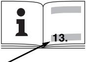 | STEB 70 Quick | STEB 80 Quick | |
| M | Nm (inlbs) | 6 (53.1) | 6 (53.1) |
| T_1 [IMAGE] | mm (in) | 70 (2^3/_4) | 80 (3^5/_32) |
| T_2 | mm (in) | 20 (^25/_32) | 25 (1) |
| T_3 | mm (in) | 6 (^1/_4) | 8 (^5/_16) |
| n_0 | min ^-1 (rpm) | 3300 | 3300 |
| P_1 | W | 570 | 590 |
| P_2 | W | 335 | 350 |
| m | kg (lbs) | 2,0 (4.4) | 2,0 (4.4) |
| a_h,CM/K_h,CM | m/s ^2 | 8,5 / 2 | 8,5 / 2 |
| a_h,CW/K_h,CW | m/s ^2 | 12 / 2 | 12 / 2 |
| L_pA/K_pA | dB(A) | 89 / 3 | 89 / 3 |
| L_WA/K_WA | dB(A) | 100 / 3 | 100 / 3 |

EN 60745
2006/42/EG, 2004/108/EG, 2011/65/EU

2012-04-03
Volker Siegle
Director Product Engineering & Quality
Responsible Person for Documentation
Metabowerke GmbH, 72622 Nürtingen, Germany
A
natural_image
Close-up of a hand using a power tool to cut a piece of material, with labeled components (no text or symbols visible)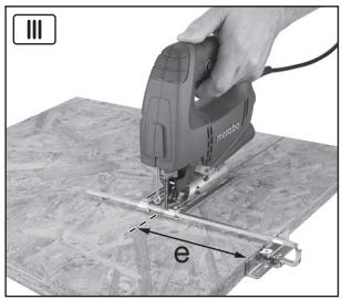
natural_image
Hand operating a hand tool on a wooden surface, with a labeled arrow indicating 'e' (no text or symbols on the object itself)Original instructions
1. Conformity Declaration
We, being solely responsible, hereby declare that these jigsaws conform to the standards and directives specified on page 3.
2. Specified Use
The machine is suitable for sawing non-ferrous metals and sheet steel, wood and similar materials, plastics and similar materials. Any other use is not permitted.
The user bears sole responsibility for damage caused by improper use.
Generally accepted accident prevention regulations and the enclosed safety information must be observed.
3. General Safety Instructions

For your own protection and for the protection of your electrical tool, pay attention to all parts of the text that are marked with this symbol!

WARNING – Reading the operating instructions will reduce the risk of injury.

WARNING Read all safety warnings and instructions. Failure to follow all safety warn-and instructions may result in electric shock, nd/or serious injury.
Keep all safety instructions and information for future reference.
Pass on your electrical tool only together with these documents.
4. Special Safety Instructions
Hold power tool by insulated gripping surfaces, when performing an operation where the cutting accessory may contact hidden wiring. Cutting accessory contacting a "live" wire may make exposed metal parts of the power tool "live" and could give the operator an electric shock.
Ensure that the spot where you wish to work is free of power cables, gas lines or water pipes (e.g. using a metal detector).
Dust from material such as paint containing lead, some wood species, minerals and metal may be harmful. Contact with or inhalation of the dust may cause allergic reactions and/or respiratory diseases to the operator or bystanders.
Certain kinds of dust are classified as carcinogenic such as oak and beech dust especially in conjunction with additives for wood conditioning (chromate, wood preservative). Material containing asbestos must only be treated by specialists.
- Where the use of a dust extraction device is possible it shall be used.
- To extract dust more efficiently, use the protective cap (9) and a suitable Metabo vacuum cleaner together with this tool.
- The work place must be well ventilated.
- The use of a dust mask of filter class P2 is recommended.
Follow national requirements for the materials you want to work with.
During work, the workpiece must lay flat and be secured against moving, e.g. using clamps.
Do not try to saw extremely small workpieces.
When sawing, the footplate must make secure contact with the workpiece.
When interrupting a cut for any reason, release the trigger and hold the saw motionless in the material until the saw blade comes to a complete stop. Never attempt to remove the saw from the workpiece while the saw blade is in motion or kickback may occur.
Do not switch the machine on while the saw blade is touching the workpiece. Let the saw blade reach full speed before making a cut.
When restarting a saw in the workpiece, centre the saw blade in the kerf and check that saw teeth are not engaged into the material. If the saw blade seizes, it may kickback from the workpiece when the saw is restarted.
Keep hands well away from the sawing area and the saw blade. Do not reach underneath the workpiece.
Remove chips and similar material only with the machine at standstill.
Pull the plug out of the socket before making any adjustments, converting or servicing the machine.
Danger of injury due to the sharp jigsaw blade. After stopping work, the jigsaw blade may still be hot. Wear protective gloves.
5. Overview
See page 2.
1 Clamping lever for securing the saw blade
2 Saw blade support roller
3 Saw blade
4 Screw for adjusting the footplate
5 Footplate
6 Switch button on the chip blower
7 Adjustment lever for pendulum motion
8 Anti-splintering footplate insert
9 Protective cap
10 Saw blade clamping fixture
11 Protective rod for preventing unintentional contact with the saw blade
12 Setting wheel for speed adjustment
13 Trigger
14 Lock button for continuous activation
15 Hexagon spanner
16 Extractor connection piece
17 Curved support plate indicating preset cutting angle
6. Commissioning

Before plugging in, check to see that the rated mains voltage and mains frequency, as stated e rating label, match your power supply.

Never operate the machine without a saw blade.
6.1 Fitting the anti-splintering footplate insert

Danger of injury due to the sharp jigsaw blade. Remove the saw blade before fitting (8) the anti-tering footplate insert.
Turn the machine over so that the footplate faces upwards. Insert the anti-splintering footplate from the front, ensuring the following:
- The smooth side of the footplate faces upwards.
- The slot is facing to the rear (towards the mains cable).
If you wish to work with the protective plate attached (see chapter Accessories 10.), fit the anti-splintering footplate insert in the protective plate.
6.2 Inserting the saw blade

Danger of injury due to the sharp jigsaw blade. After stopping work, the jigsaw blade may still not. Wear protective gloves.
Use a saw blade that is suitable for the material being sawn.
- Push the clamping lever (1) forwards up to the stop and release (the clamping lever remains open).
- Insert the saw blade (3) up to the stop. Ensure that the saw teeth are facing forwards and the blade is seated correctly in the groove on the saw blade support roller (2).
- Push back the clamping lever (1) to its original position (the saw blade is now clamped securely in position).
6.3 Attaching / Removing the protective cap
Attachment: Push on the protective cap (9) from the front until it engages
Removal: Grip both sides of the protective cap (9), lift slightly, then pull forwards and remove.
6.4 Sawing with dust extraction
- Connect a suitable extraction device to the extractor connection piece (16). Use a suction hose with a 30 mm connector diameter.
- Attach the protective cap (9) for maximum extraction efficiency.
- Switch off the chip blower (see chapter 7.1).
6.5 Sawing without dust extraction
- Work with the protective cap (9) removed (see Removal chapter 6.3).
6.6 Diagonal cuts
Remove the protective cap (9), anti-splintering footplate insert (8) and extraction hose. These parts cannot be used for diagonal cuts.
- Slacken the screw (4).
- Slid the footplate (5) forwards slightly and turn.
- Then slide the footplate (5) forwards or backwards and engage in one of the detents (the detents can be viewed through the semicircular opening at the rear of the footplate (5).) The preset angle is indicated on the curved support plate (17) on the footplate. Adjust to different angles using an angle gage.
- Tighten the screw (4) again.
6.7 Sawing close to the wall
Remove the protective cap (9), anti-splintering footplate insert (8), circular-cutting and parallel guide. These parts cannot be used when sawing close to the wall.
- Slacken the screw (4) until the footplate (5) can be raised slightly.
- Raise the footplate (5) slightly and slide backwards up to the stop.
- Tighten the screw (4) again.
7. Use
7.1 Chip blower
Optional blower for a clear view of the cutting line.
On: press in the switch button (6) on the right side of the machine. (look for the ➞ symbol).
Off: press in the switch button (6) on the left side of the machine. (look for the ✗ symbol).
7.2 Adjusting the pendulum motion
Set the required pendulum motion using the adjustment lever (7).
Position "0" = pendulum motion is switched off
Position "III" = maximum pendulum motion See page 3 for recommend setting values.
The best way to determine the ideal setting is through a practical trial.
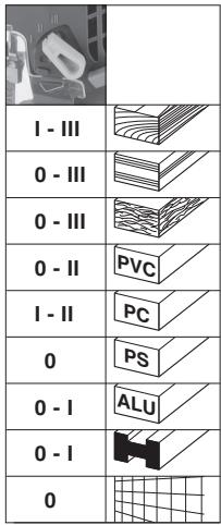
7.3 Setting maximum speed
Set the machine to maximum speed using the setting wheel (12). This is also possible during operation.
See page 3 for recommend setting values.
The best way to determine the ideal setting is through a practical trial.
7.4 Switching on and off, adjusting the speed, continuous operation
On: press the trigger (13). Press the trigger more to increase the speed (up to preset maximum speed, see chapter 7.3).
Off: release the trigger (13).
Continuous operation: For continuous operation, the pressed trigger (13) can be locked using the lock button (14). To stop the machine, press the trigger (13) again.

In continuous operation, the machine continues running if it is forced out of your
hands. Therefore always hold the machine with both hands using the handle provided, stand securely and concentrate.
8. Cleaning, Maintenance
Clean the machine regularly. This includes vacuum cleaning the ventilation louvres on the motor.
Clean the saw blade clamping fixture regularly and thoroughly by blowing with compressed air.
If necessary, clean the openings behind the saw blade support roller (2).
Apply a drop of oil to the saw blade support roller (2) from time to time.
9. Tips and Tricks
Plunging
The jigsaw blade can plunge into workpieces made from thin, soft materials without the necessity of drilling a hole beforehand. Only use short saw blades. Only at 0^ angle setting.
See illustration on page 2. Set the adjustment lever (7) to position "0" (pendulum motion is switched off). Position the jigsaw with the front edge of the footplate (5) on the workpiece. Hold the operating jigsaw firmly and guide slowly downwards. Once the saw blade has penetrated the workpiece, the pendulum motion can be activated.
In thicker workpieces, a hole for inserting the saw blade must be drilled first.
10. Accessories
Use only genuine Metabo accessories.
Use only accessories which fulfil the requirements and specifications listed in these operating instructions.
Fit accessories securely. Secure the machine if it is operated in a bracket. Loss of control can cause personal injury.
See page 4.
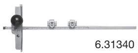
A Circular-cutting and parallel guide For complete range of accessories, visit www.metabo.com or refer to the main catalogue.
10.1 Attaching the circular-cutting and parallel guide
For sawing circles (dia. 100 - 360 mm) and making cuts parallel with edges (max. 210 mm).
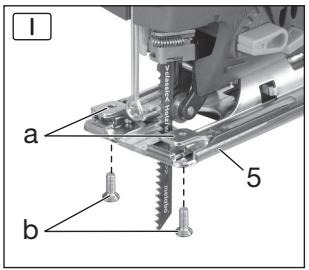
Attaching clamping elements (page 4, Fig. I)
Place the clamping elements (a) on the footplate (5) with the opening facing forwards and the threaded hole facing up. Insert the screws (b) from underneath.

Remove the clamping elements after use otherwise the saw blade clamping fixture (10)
may be damaged when diagonal cuts are made.
At a 45^ diagonal cut angle, tilting the jigsaw to the right will damage the saw blade clamping fixture (10).
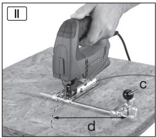
Attaching the circular-cutting guide (page 4, Fig. II)
Attaching the parallel guide (page 4, Fig. III)
- Slide the rod on the circular-cutting and parallel guide sideways into the clamping elements (a) (centre point (c) faces downwards).
- Set the desired radius (d).
- Tighten the screws (b).
- Slide the rod on the circular-cutting and parallel guide sideways into the clamping elements (a) (centre point (c) faces upwards).
- Unscrew the centre point (c).
- Set the dimension (e)
- Tighten the screws (b).
11. Repairs

Repairs to electrical tools must be carried out by qualified electricians ONLY!
If you have Metabo electrical tools that require repairs, please contact your Metabo service centre. For addresses see www.metabo.com.
You can download spare parts lists from www.metabo.com.
12. Environmental Protection
Observe national regulations on environmentally compatible disposal and on the recycling of disused machines, packaging and accessories.

Only for EU countries: Never dispose of power tools in your household waste! In accordance with European Guideline 2002/ on used electronic and electric equipment implementation in national legal systems, power tools must be collected separately and in for environmentally compatible recycling.
13. Technical Specifications
Explanatory notes on the specifications on page 3. Changes due to technological progress reserved.
| M | =Torque |
| T_1 | =Maximum material thickness in wood |
| T_2 | =Maximum material thickness in non-ferrous metals |
| T_3 | =Maximum material thickness in sheet steel |
| n_0 | =Stroke rate at idle speed |
| P_1 | =Nominal power input |
| P_2 | =Power output |
| m | =Weight without mains cable |
Measured values determined in conformity with EN 60745.
□ Machine in protection class II
\~ Alternating current
The technical specifications quoted are subject to tolerances (in compliance with the relevant valid standards).

Emission values
These values make it possible to assess the emissions from the power tool and to compare different power tools. Depending on the operating conditions, the condition of the power tool or the accessories, the actual load may be higher or lower. For assessment purposes, please allow for breaks and periods when the load is lower. Based on the adjusted estimates, arrange protective measures for the user e.g. organisational measures.
Vibration total value (vector sum of three directions) determined in accordance with EN 60745:
$$ \begin{array}{l} \begin{array}{r l} a _ {h, C M} & = \text { Vibration emission value } \ & \text {(sawing sheet metal)} \end{array} \ \begin{array}{r l} {a _ {h, C W}} & {= \text { Vibration emission value }} \ & {\text {(sawing wood)}} \end{array} \ K _ {h, \dots} = \text { Uncertainty (vibration) } \ \end{array} $$
Typical A-effective perceived sound levels:
$$ L _ {p A} = \text { Sound pressure level } $$
$$ L _ {W A} ^ {\prime} = \text { Acoustic power level } $$
$$ K _ {p A}, K _ {W A} = \text { Uncertainty } $$

Wear ear protectors!
Notice originale
L_pA =äänenpainetaso
L_WA =