59G801 - Saw Graphite - Free user manual and instructions
Find the device manual for free 59G801 Graphite in PDF.


| Product Type | Saw |
| Brand | Graphite |
| Model | 59G801 |
| Power Source | Electric (corded) |
| Voltage | 230 V |
| Frequency | 50 Hz |
| Power Input | 1200 W (typical) |
| Blade Diameter | 190 mm (typical) |
| Max Cut Depth at 90° | 55 mm (typical) |
| No-Load Speed | 5000 rpm (typical) |
| Weight | 3.5 kg |
| Dimensions (L x W x H) | 300 x 200 x 250 mm |
| Main Functions | Cutting wood, plastic, metal; adjustable cutting depth; parallel guide; dust extraction port |
| Safety Features | Blade guard, spindle lock, double insulation, safety switch |
| Maintenance | Regular cleaning of ventilation slots, lubrication of moving parts, carbon brush replacement |
| Spare Parts Available | Blades, carbon brushes, saw blade wrench, parallel guide |
| Repairability | User-serviceable parts: blade, brushes; professional repair for motor |
| Accessories Included | Rip fence, blade wrench, dust bag (optional) |
Frequently Asked Questions - 59G801 Graphite
User questions about 59G801 Graphite
0 question about this device. Answer the ones you know or ask your own.
Ask a new question about this device
Download the instructions for your Saw in PDF format for free! Find your manual 59G801 - Graphite and take your electronic device back in hand. On this page are published all the documents necessary for the use of your device. 59G801 by Graphite.
USER MANUAL 59G801 Graphite
SR UNIVERZALNA TESTERA
natural_image
Mechanical device with mounted components and a central dial (no visible text or symbols)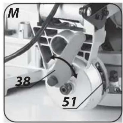
natural_image
Diagram of a mechanical spring assembly with a central component, no text or symbols present
INSTRUKCJA ORYGINALNA (OBSŁUGI)
PILARKA UNIWERSALNA 59G801
UWAGA: PRZED PRZYSTĄPIENIEM DO UŻYTKOWANIA ELEKTRONARZĘDZIA NALEŻY UWAŻNIE PRZECZYTAĆ NINIEJSZĄ INSTRUKCJĘ I ZACHOWAĆ JĄ DO DALSZEGO WYKORZYSTANIA.
SZCZEGÓŁOWE PRZEPISY BEZPIECZEŃSTWA
PILARKA UNIWERSALNA, OSTRZEŻENIA DOTYCZĄCE BEZPIECZEŃSTWA
/The above listed product is in conformity with the following UE Directives:/
GTX
SERVICE
Paweł Kowalski
/GRUPA TOPEX Quality Agent/
CAUTION: BEFORE USING THE POWER TOOL READ THIS MANUAL CAREFULLY AND KEEP IT FOR FUTURE REFERENCE.
DETAILED SAFETY REGULATIONS
SAFETY WARNINGS FOR FLIP OVER SAW
- When operating the saw strictly follow applicable regulations regarding occupational health and safety.
- Use only cutting blades recommended by the manufacturer, conforming with the standard EN 847 1.
- When replacing cutting blade remember that its width must not exceed width of the riving knife.
- Make sure the cutting blade is suitable for material that you plan to cut.
- Do not use cutting blades made of high speed steel (HSS). Blades made of HSS steel can break easily.
- Make sure direction of cutting blade rotation matches indicated direction of the saw motor.
- Use only cutting blades with allowable maximum speed greater than maximum speed of the table saw spindle.
- Use only sharp cutting blades, free from cracks and deformations.
- Cutting blade of the saw should be free to rotate.
• Always use well positioned riving knife and properly adjusted upper guard of the cutting blade.
- Before using the saw make sure the blade guard is free to move. Position the blade guard so it lightly rests on the processed material. Never fix the guard in open position.
- Put the processed piece to the blade when it is rotating. Switching on the blade rotation with processed piece already pressed against it may cause blade jamming in the processed piece or result in kick back.
- In case the blade jams in material switch off the tool and firmly hold the processed piece. To avoid kick back, you can move the processed piece only when the blade comes to complete stop. Resolve the cause of blade jamming before starting it again.
- Use a push stick to feed material towards the cutting blade.
- When cutting wood that has already been used, ensure it is free from unwanted objects, such as nails, screws etc.
• Always use anti-splinter goggles, hearing protection and anti-dust mask.
• Always wear proper clothing for your work! Loose items of clothing or jewellery might get caught by rotating cutting blade.
- Before each adjustment, measurement, cleaning or removing jammed pieces of wood disconnect the tool from power supply with the switch and remove the plug from mains socket!
- After repair or maintenance is carried out, install all guards and protective parts before switching on the flip over saw.
- Power supply voltage must match value marked on the rating plate of the saw.
- Connect the saw only to electrical system equipped with residual current circuit breaker that will cut the power off in less than 30 ms when earth leakage current exceeds 30 mA.
- When working outdoors use only extension cords designed for outdoor use.
- Do not use the saw for cutting firewood.
- Never keep your hands in position, where there is a risk of unexpected sliding and contact with the cutting blade.
- Never remove saw dust from the saw workplace when the saw is switched on.
• Always fix working piece. Do not process pieces too small to fix securely. - Do not start working with the saw when tired or under influence of medicines.
- It is vital that all persons who operate the saw are properly trained for operation, adjustments and using the saw.
- Do not operate or leave the saw in places exposed to rain or humidity.
- Never use the saw close to explosive liquids or gases.
- Saw operator should be an adult person.
- Bystanders should not stay close to connected or operating saw.
- Check technical condition of the power cord periodically. Never use the saw with damaged power cord.
- Never attempt to repair the saw by yourself. In case of damage take the saw to authorised service shop for repair.
- Replace damaged protective parts immediately.
- Never overload the saw, causing blade rotational speed to drop down considerably.
- Keep the workplace clean. Remove waste wood material and unnecessary objects before starting to work.
- Keep the workplace well illuminated.
- Do not distract person who is working with the saw.
- Avoid contact with earthed parts, pipes, heat radiators, cookers, refrigerators when working with the saw.
• After the motor is switched off with the switch, never attempt to stop the cutting blade by applying side pressure.
- Immediately replace damaged cutting blade.
- Use protection gloves for cutting blade replacement.
- Never use cutting blades with parameters different from specified in this manual.
- Never attempt to remove or disconnect protection parts of the saw.
- When you need a break, finish current cutting and switch off the saw.
- When a break in work and leaving the workplace is necessary, switch off the saw with the switch and disconnect it from power supply by removing the plug from mains socket.
- Do not touch the blade after cutting until the blade cools down. The blade heats up very quickly during operation.
- Check technical condition of the saw before operation:
- all protection parts must be in good working condition and operate as supposed to,
- screws and other fixing parts must not be loosened,
- all unwanted objects, like keys used for blade assembly, must be removed from the saw working area.
- Do not store material or tools above the saw.
- Always ensure the processed material adheres to the work table of the saw with its whole surface.
- When cutting long objects use appropriate supports, so the cutting blade does not jam in the material.
- When cutting round pieces of material use clamps to prevent material from rotating when making a cut.
- Never cut several pieces of material at a time.
- When cutting narrow pieces of material use included push stick. Do not cut material that you cannot hold safely.
- Never attempt removing pieces of material, sawdust or other objects when cutting blade of the saw is rotating.
- External dust extraction system should be connected when the saw is operating.
- Do not unplug the saw from mains socket by pulling the cord. Protect the power cord against excessive heat, oil and sharp edges.
- When operating the saw keep your body in firm, standing position.
- All parts of the saw must be properly fixed.
- Do not make profile or plunge cuts with the saw.
- When carrying the tile saw, hold only by carrying handles, do not hold by saw guards.
- Upper part of the cutting blade must be covered with the guard when carrying the saw
Safety conditions for flip over saw
- When operating the saw strictly follow applicable regulations regarding occupational health and safety.
- Use only cutting blades recommended by the manufacturer, conforming with the standard PN-EN 847-1.
- When replacing cutting blade remember that its width must not exceed width of the riving knife.
- Make sure the cutting blade is suitable for material that you plan to cut.
- Use only cutting blades with allowable maximum speed greater than maximum speed of the saw spindle.
- Do not use cutting blades made of high speed steel (HSS) or with parameters different from specified in this manual.
- Use only sharp cutting blades, free from cracks and deformations.
- Immediately replace damaged cutting blade.
- Make sure direction of cutting blade rotation matches indicated direction of the saw motor.
- Cutting blade of the saw should be free to rotate.
- Always use well positioned riving knife and properly adjusted upper guard of the cutting blade.
- Use a push stick to feed material towards the cutting blade.
- When cutting wood that has already been used, ensure it is free from unwanted objects, such as nails, screws etc.
- Always use anti-splinter goggles, hearing protection and anti-dust mask.
- Use gloves when handling cutting blades and to protect against other rough and sharp materials. (When replacing a cutting blade hold it by its hole whenever possible.)
- Always wear proper clothing for your work! Loose items of clothing or jewellery might get caught by rotating cutting blade.
- Before any adjustment, measurement, cleaning or removing jammed pieces of wood always disconnect the tool from power supply with the switch and remove the plug from mains socket!
- After repair or maintenance is carried out, install all guards and protective parts before switching on the saw.
- Power supply voltage must match value marked on the rating plate of the saw.
- Connect the saw only to electrical system equipped with residual current circuit breaker that will cut the power off in less than 30 ms when earth leakage current exceeds 30 mA.
- When working outdoors use only extension cords designed for outdoor use.
- Do not use the saw for cutting firewood.
- Do not keep your hands in position, where there is a risk of unexpected sliding and contact with the cutting blade.
- Do not start working with the saw when tired or under influence of medicines.
- It is vital that all persons who operate the saw are properly trained for operation, using and adjustments of the saw.
- Do not operate, store or leave the saw in places exposed to rain or humidity.
- Never use the saw close to explosion hazardous liquids or gases.
- Saw operator should be an adult person.
- Bystanders should not stay close to connected or operating saw.
- Check technical condition of the power cord periodically.
- Do not use the saw if the power cord is damaged.
- Replace damaged protective parts immediately.
- Do not overload the saw, causing rotational speed to drop down considerably.
- Keep the workplace clean.
- Remove waste wood material and unnecessary objects before starting to work.
- Keep bystanders away from the saw workplace.
- Keep the workplace well illuminated.
- Do not distract person who is working with the saw.
- Avoid contact with earthed parts, pipes, heat radiators, cookers, refrigerators when working with the saw.
• After the motor has been switched off with the switch, do not attempt to stop the cutting blade by applying side pressure.
- Do not attempt to remove or disconnect protection parts of the saw.
- When you need a break, finish current cutting and switch off the saw.
- When a break in work and leaving the workplace is required, switch off the saw with the switch and disconnect it from power supply by removing the plug from mains socket.
- Do not unplug the saw from mains socket by pulling the cord.
- Protect the power cord against excessive heat, oil and sharp edges.
- Attach the saw firmly to a workbench (if adapted).
• The saw cannot be used for grooving.
- Check technical condition of the saw before starting to operate, in particular:
- all protection parts must be in good working condition and operate as supposed to,
- screws and other fixing parts must not be loosened,
- all adjustment keys must be removed from the tool.
- Do not store material or tools above the saw.
- Always ensure the processed material adheres to the work table of the saw with its whole surface.
- When cutting long objects use appropriate supports, so the cutting blade does not jam in the material.
- When cutting round pieces of material use clamps to prevent material from rotating when making a cut.
- Do not cut several pieces of material at a time.
- Do not cut material that you cannot hold safely.
- Never attempt to remove pieces of material, sawdust or other objects when cutting blade of the saw is rotating.
- External dust extraction system should be connected when the saw is operating.
- When operating the saw keep your body in firm, standing position.
- All parts of the saw must be properly fixed.
- Do not hold the saw guards when carrying the saw.
- During transportation the cutting blade must be covered with the guard.
- If the saw is equipped with laser, replacement with laser unit of another type is forbidden.
- Do not attempt to repair the saw by yourself.
- Repairs should only be carried out by qualified person in authorized service workshop and with use of original spare parts.
- Make sure that upper part of the cutting blade is completely guarded when operating in mitre saw mode.
CAUTION! This device is designed to operate indoors.
The design is assumed to be safe, protection measures and additional safety systems are used, nevertheless there is always a small risk of injuries at work.
Explanation of used symbols

1
2
3
4

5

6
7
8
- Read instruction manual, observe warnings and safety conditions therein.
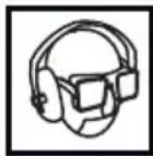
- Use personal protection measures (protective goggles, earmuff protectors, anti-dust half mask).
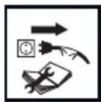
- Disconnect the power cord before starting maintenance or repair.
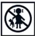
- Keep the tool away from children.
- Protect against rain.
- Protection class 2.
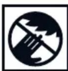
- Keep hands away from the work area of the saw.
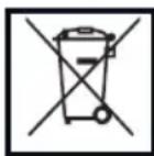
- Segregated waste collection.
CONSTRUCTION AND USE
Flip over saw is designed for cutting wood and wood-like materials. The tool can be used in table saw mode or mitre saw mode. Quick and tool free change of function facilitates operation. Output power allows to cut hard and soft wood, chipboards and fibreboard. When operating in table saw mode do not cut aluminium or other non-ferrous metals. Do not use the saw for cutting firewood. Use the table saw only with appropriate cutting blades with teeth with solid carbide inserts. Flip over saw is designed for light duty works in service workshops, repair and construction tasks and all individual, amateur activities (tinkering).

Use the tool only in accordance with its purpose.
DESCRIPTION OF DRAWING PAGES
Below enumeration refers to the device elements depicted on the drawing pages of this manual.
TABLE SAW (ITEMS)
- Riving knife
- Cutting blade guard
- Work table
- Ripping fence
- Preview window
-
Ripping fence fixing lever
-
Switch
- Saw dust extraction insert
- Fixing holes
- Saw dust extraction outlet
- Knobs for lifting/lowering work table
- Spindle lock button
- Cutting blade
- Riving knife fixing screws
- Crosscut fence
- Mitre gauge slot
- Angle scale
- Angle indicator
- Locking knob of the mitre gauge
- Locking knobs of the crosscut fence
- Locking knob for angle setting
- Mitre gauge
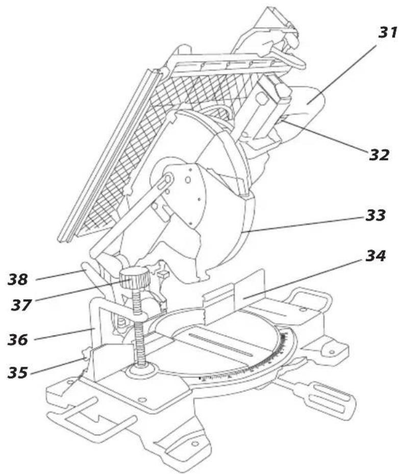
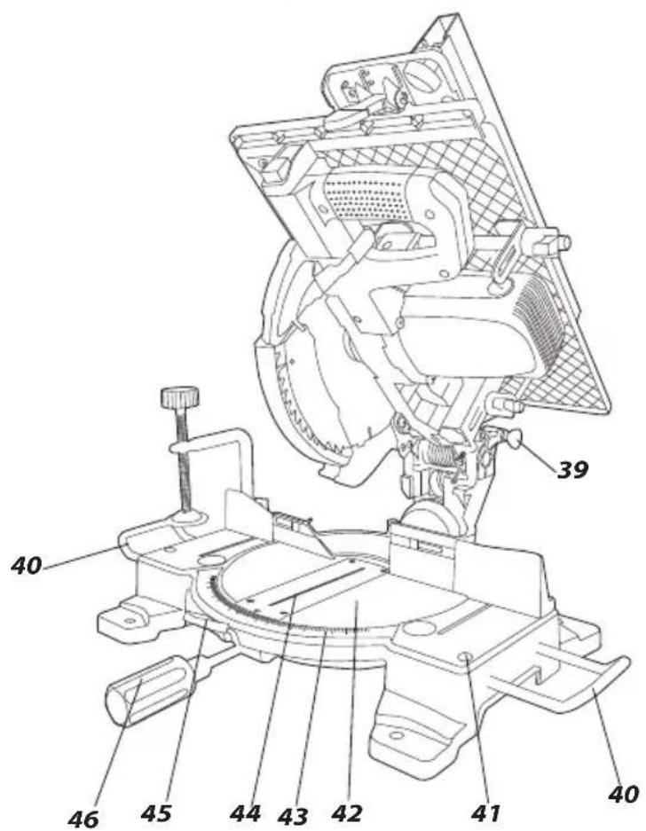
MITRE SAW (ITEMS)
- Handle grip
- Moving guard locking lever
- Movable guard
- Fence
- Vertical clamp arm locking knob
- Vertical clamp
- Vertical clamp locking knob
- Head tilt locking lever
- Head locking pin
- Turntable extension
-
Locking screw of table extension
-
Turntable
-
Angle scale of turntable
-
Turntable insert
-
Turntable lock button
-
Turntable locking knob
-
Dust extraction outlet
-
Stopping fender
-
Adjustment screw
-
Lock nut
-
Angular scale of head tilt
-
Adjustment screw for 90° angle
-
Nut
-
Adjustment screw for 45^ angle
-
Nut
-
Screw
-
Cover
-
Fixing bolt for cutting blade
-
Outer flange
-
Carbon brush cover
* Differences may appear between the product and drawing.
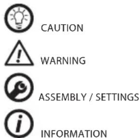
MEANING OF SYMBOLS
EQUIPMENT AND ACCESSORIES
| 1. Vertical clamp | - | 1 | pce |
| 2. Mitre gauge + crosscut fence | - | 1 | pce |
| 3. Ripping fence | - | 1 | pce |
| 4. Saw dust extraction insert | - | 1 | pce |
| 5. Pusher | - | 1 | pce |
Ensure the flip over saw is disconnected from power supply before starting any installation or adjustment.
FLIP OVER SAW INSTALLATION ON A WORKSHOP BENCH

It is recommended to fix the saw to a workbench or a stand with the use of fixing holes (9) designed for such purpose. They are located on the saw base and guarantee safe operation and eliminate risk of unwanted machine shifts during operation. The fixing holes allow to use coach bolts or bolts with hexagonal head and 8 mm in diameter.

When fixing the mitre saw to a workbench ensure that:
• Workbench top surface is flat and clean.
- Bolts are tightened equally and with moderate force (fixing bolts must be tightened so the base is not under stress or deformed). In case of over-stress there is danger of cracking the base.
TRANSPORT

Before moving the tool follow the procedure:
- Set up the tool in table saw mode.
- Carry when holding the base with two hands.
Ensure the saw is disconnected from power supply network before starting any adjustment. To ensure safe, precise and efficient saw operation, proceed with all adjustment procedures as a whole.
After finishing all the setting and adjustment procedures ensure that all adjustment keys are collected. Check that all joining elements are properly fitted.
When making adjustments ensure that all external parts work properly and conform with all conditions necessary for proper operation. Any worn out or damaged part must be replaced by qualified personnel before starting to use the saw.
INSTRUCTIONS FOR CUTTING

- It is recommended to make a try cut after each adjustment to make sure the new settings are correct and to check dimensions.
• After switching the saw on, wait until cutting blade reaches its top maximum speed while running idle, only then you can proceed with cutting.
- Secure long objects from falling after cutting (e.g. with a roller support).
- Be very careful when starting a cut!
- When cutting wood that has already been used, ensure it is free from unwanted objects, such as nails, screws etc.
- Wait until cutting blade comes to a complete stop, only then you can remove cut off pieces.
- Always hold main part of the processed material. Never hold the part that is being cut off.
USE IN TABLE SAW MODE
DUST EXTRACTION

To prevent accumulation of saw dust and provide maximum cutting efficiency:

- Lift the saw arm to maximum height in mitre saw mode.
- Put saw dust extraction insert (8) on the turntable (42) in the mitre saw mode so the insert stays in its clips.
- Lower and lock the saw arm in table saw mode.
- Connect industrial vacuum cleaner to the saw dust extraction outlet (10) in saw dust extraction insert (8).
CHECKING POSITION OF THE RIVING KNIFE
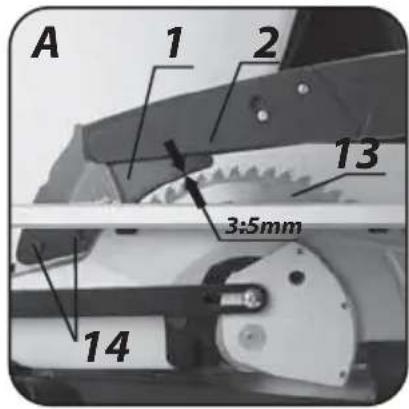
Set the riving knife (1) so the distance between the cutting blade (13) and the riving knife (1) is between 3 and 5 mm (the riving knife should be positioned exactly in line with the cutting blade) (fig. A). Check position of the riving knife after each replacement of cutting blade.
CUTTING BLADE GUARD
Attach the cutting blade guard (2) so it lifts as the material is fed towards the cutting blade (13) and freely falls after the cutting is finished.

RIPPING FENCE INSTALLATION
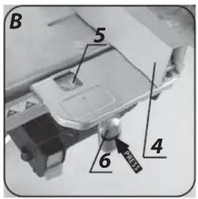
- Slide fixing of the ripping fence (4) into guide slot in the work table (3).
- Set up the ripping fence (4) in required position (use the preview window (5)) and secure with the ripping fence fixing lever (6) (fig. B).
- It is recommended to make a try cut, measure and if necessary readjust the ripping fence.

To prevent seizing of processed material you can shift the ripping fence (4) lengthwise when the ripping fence fixing knob and screw are loosened.

SWITCHING ON / SWITCHING OFF
The mains voltage must match the voltage on the rating plate of the saw. Switch on the saw only when the processed material is away from the cutting blade.

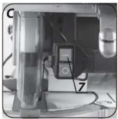
Switching on - press the button I of the switch (7) (fig. C).
Switching off – press the button O of the switch.

CUTTING DEPTH ADJUSTMENT
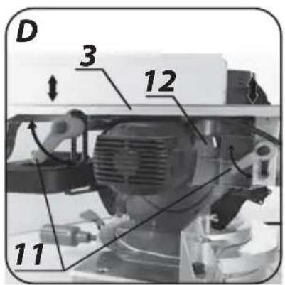
- Loosen the knobs for lifting/lowering work table (11).
- Set up the work table (3) to desired cutting depth.
- Lock the selected position with the knobs for lifting/lowering work table (11) (fig. D).


You can pull and release the work table to change placement of the lever of knob for lifting/lowering work table (11).
The saw should be adjusted so the highest point of the cutting blade is just above the surface of the material being cut.

MITRE CUTTING WITH USE OF THE MITRE GAUGE
The mitre gauge is installed on the left side of the work table.
- Remove the ripping fence (4) from the work table top (3).
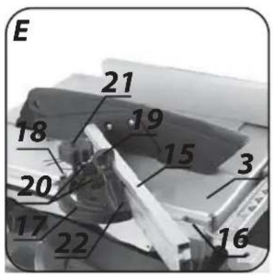
- Slide the mitre gauge (22) guide into the mitre gauge slot (16).
- Install the crosscut fence (15) to the mitre gauge (22) with the locking knobs of the crosscut fence (20). Use the angle scale (17) to set required cutting angle and secure with the locking knob for angle setting (21).
- Lock the mitre gauge (22) with the locking knob (19) (fig. E).
- Position the crosscut fence (15) so it cannot come into contact with the cutting blade (it is possible to shift the crosscut fence).
- Before starting the saw make sure that the crosscut fence (15) is approximately 2 cm away from the cutting blade.
- Firmly push processed material against the crosscut fence (15).
- Switch on the saw and feed the processed material towards the blade to make a cut.

Always move the material being cut far enough to complete the cutting.
When cross-cutting do not use ripping fence as a length limiter for piece of material being cut off, because this piece may jam between the ripping fence and the cutting blade, and cause kick back effect.

RIPPING

Ripping is cutting the material to desired width along its whole length.
- Set the ripping fence (4) to appropriate cutting width.
- Switch the saw on and wait until cutting blade reaches its full rotational speed.
- Press the material against the ripping fence (4) and move towards cutting blade to the end of the riving knife (1) (use the push stick when close to cutting blade).
- Leave the cut material on the work table until the cutting blade stops completely after switching off the saw.


It is recommended to make a try cut after each adjustment to make sure the new setting is correct. When making a cut stand to the side of the line of cutting.
CUTTING SMALL OBJECTS

- Set the ripping fence (4) to appropriate cutting width.
- Feed the material with both hands. When getting close to the cutting blade always use the push stick (included) to move the material or use additional piece of wood to push material being cut against the ripping fence (4).
• Always push the cut material to the end of the riving knife (1).


When cutting short and narrow objects, use the push stick from the beginning.
USE IN MITRE SAW MODE
USING THE EXTENSION ARM (HEAD)

There are two positions of the extension arm, upper and lower. To release the head from locked lower position, do as follows:
- Remove the ripping fence (4) and the mitre gauge (22).
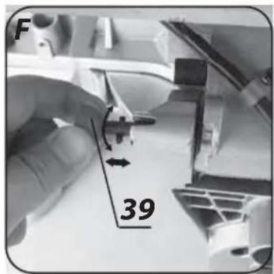
• Lightly press the handle grip (31) and hold. - Pull the head locking pin (39) away, so its safety bolt slides out of the locking hole.
- Turn the head locking pin (39) by 90^ and lock in the position (fig. F).
- Press in the moving guard locking lever (32).
- Hold the extension arm as it lifts to its upper position.
- You can lock the extension arm in lower position by following unlock procedure in reverse order after releasing the moving guard locking lever (32).

VERTICAL CLAMP

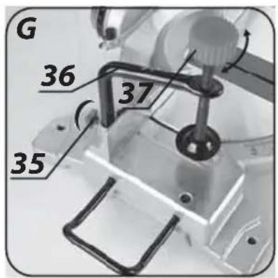
Vertical clamp (36) can be installed in the saw base at either side and is fully adjustable to size of the object to be cut. Do not use the saw without using vertical clamp (fig. G).

- Loosen the vertical clamp arm locking knob (35) at the side to install the vertical clamp.
- Slide the vertical clamp (36) into hole in the saw base to install it in place.
- Once the vertical clamp arm (36) position is adjusted to work piece, tighten the vertical clamp arm locking knob (35).
- Tighten the vertical clamp locking knob (37) so it presses the processed piece to the saw base.
• Make sure the work piece is secured.

Always fix processed material in place to guarantee optimal work safety. Do not cut objects too small to fix in place.
INSTALLATION AND REMOVAL OF THE TURNTABLE EXTENSIONS
Installation of additional turntable extensions improves working surface of the table and makes cutting long objects significantly easier. Turntable extensions can be installed at left and right side of the saw base.
- Loosen the locking screws of table extensions (41).
- Slide the bars of turntable extensions (40) into holes in the saw base.
- Set required length and tighten the locking screws of table extensions (41).
- Deinstallation is similar to the installation procedure in reverse sequence.
DUST EXTRACTION
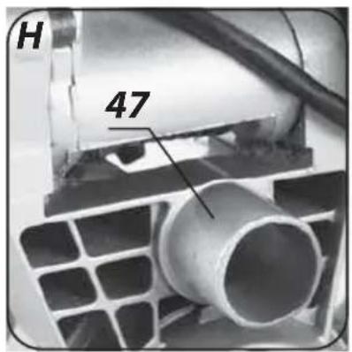
Whenever more efficient dust extraction is required for health hazardous carcinogenic dusts, attach hose of suction device to the dust extraction outlet (47) (fig. H).
CHECKING AND ADJUSTMENT OF CUTTING DEPTH
Before starting to work it is necessary to check maximal cutting depth, to make sure the cutting blade will not touch flip over saw base.
- Set the turntable (42) and the extension arm to 0^ position.
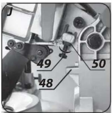
- Lower the extension arm and hold it in this position, pressed against the stopping fender (48).
- Turn the cutting blade by hand to make sure it is free to move.
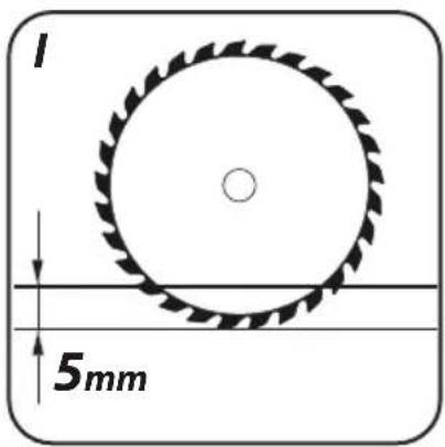
- Proper adjustment of full cutting depth should allow cutting blade to penetrate 5 mm below the upper surface of the turntable (42) (fig. I).
- In case the setting is wrong, loosen the lock nut (50) and turn the adjustment screw (49) clockwise or counter-clockwise until cutting blade penetration depth is appropriate (fig. J).
• After adjustment lock the adjustment screw (49) with the lock nut (50).
SWITCHING ON / SWITCHING OFF
The mains voltage must match the voltage on the rating plate of the saw. Switch on the saw only when cutting blade is away from the material that is to be cut.
Switching on
- Press the switch button I (7).
Switching off
- Press the switch button O (7).
CUTTING OFF NARROW PIECES OF MATERIAL
Cutting off is used mostly for narrow pieces of material. Before starting to cut ensure that the table rotation locking knob (46) and the locking lever for cutting blade tilt (38) are firmly tightened.
• Fix the material to the turntable, consider its size.
- Set desired cutting angle.
- Unlock the extension arm and the cutting blade guard.
- Press the switch button (7) (wait until cutting blade reaches its top rotational speed).
- Hold the handle grip (31) and slowly bring down the extension arm. Make a cut by applying moderate pressure.
- Switch off the saw and wait until the cutting blade stops completely.
- Slowly lift the extension arm.

Insufficient tightening of the table rotation locking knob may cause unexpected move of cutting blade to upper surface of the material. It puts operator in danger of being hit with piece of material.
SETTING THE TURNTABLE FOR MITRE CUTTING
The turntable (42) allows cutting material at any angle within range of 45^ left or right from the perpendicular position.
- Pull and turn the head locking pin (39) and allow the extension arm to lift slowly to upper position.
- Loosen the table rotation locking knob (46).
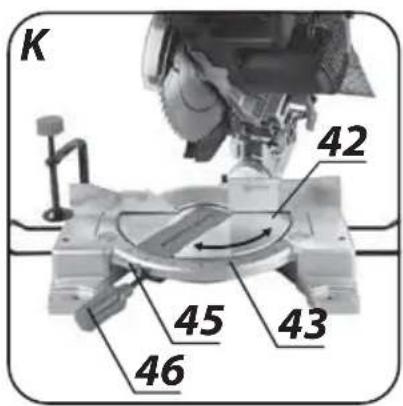
- Press the turntable lock button (45) and set the turntable (42) at desired angle. Use the angle scale of turntable (43) (fig. K).
- Lock by tightening the table rotation locking knob (46).

There are many grooves in the turntable (42) that are used to easily pick frequently used angles. Those are cutting angles that are used most often (0^, 15^, 22.5^, 30^, 45^ left or right). Any angle can be set precisely with the use of the angle scale of turntable (43) scaled every degree. Even though the scale is accurate enough for most of performed tasks, it is recommended to double check the cutting angle with protractor or other device for angle measurements.

When using standard angle quick setup, the pawl should clearly sound snapping into the groove.
SETTING THE EXTENSION ARM (HEAD) FOR BEVEL CUTTING

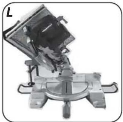
Extension arm can be tilted left at any angle from the range of 0^ to 45^ (left) for bevel cutting (fig. L).
- Pull the head locking pin (39) that releases the extension arm and allow the extension arm to lift slowly to upper position.
- Loosen the head tilt locking lever (38).
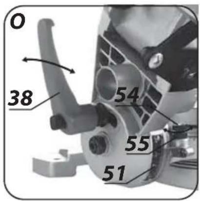
- Tilt the extension arm left to desired angle that you can read on the angular scale of head tilt (51) (fig. M).
- Tighten the head tilt locking lever (38).

If you need to set both angles (in both planes, horizontal and vertical) for compound cutting, always set the bevel angle first.
CHECKING AND ADJUSTMENT OF PERPENDICULAR POSITION OF CUTTING BLADE AND TURNTABLE
To guarantee precise cuts, check basic setup parameters of the saw after some time of operation and readjust if necessary.
- Loosen the head tilt locking lever (38).
- Set the head in the extreme right position (perpendicular to the turntable) and tighten the head tilt locking lever (38).
- Loosen the table rotation locking knob (46).
- Set the turntable (42) in 0^ position and tighten the table rotation locking knob (46).
- Press the moving guard locking lever (32) and lower the saw head to the extreme down position.
- Use the tool to check perpendicularity of cutting blade and the turntable (42).

When making measurements make sure that measurement device does not touch any cutting blade tooth, otherwise the measurement may be inaccurate due to thickness of sintered carbide insert.

In case the measurement angle is different than 90^ , the following adjustment is necessary:
- Tilt the saw head to the left.
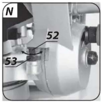
- Turn the adjustment screw (52) clockwise or counter-clockwise to increase or reduce head tilt angle. Lock with the nut (53) (fig. N).
- After perpendicular position of cutting blade and the turntable has been set, allow the head to return to its upper position.

Carry out similar adjustment for 45^ head bevel angle, using adjustment screw (54) and the nut (55) located on the opposite side of the extension arm (fig. O).

Unplug the power cord from mains socket before commencing any activities related to installation, adjustment, repair or maintenance.
CLEANING
- When the work is finished, remove thoroughly all pieces of material, shavings and dust from the work table, area around cutting blade and its guard.
- Optimally clean the saw with brush or stream of compressed air at low pressure.
- Never use water or other chemical liquids for cleaning the saw.
- Keep all handles and knobs clean.
- Clean ventilation holes regularly to prevent motor overheating.
- Store the saw in a dry place, beyond reach of children.
- Entrust replacement of power cord and other repairs only to authorized service workshop.

Regularly check that all bolts and fixing screws are tightened. They may get loosened after some time of the operation.
CUTTING BLADE REPLACEMENT
Replace the cutting blade when the tool is set up in mitre saw mode.
• Pull the head locking pin (39) to unlock the extension arm.
- Allow smooth return of the extension arm to upper position.
- Press and hold the moving guard locking lever (32).
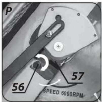
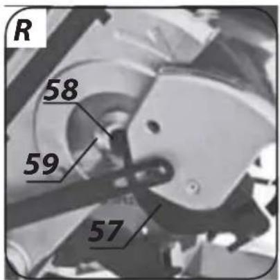
- Shift the movable guard (33) up, undo the screw (56) and push away the cover (57) (fig. P), to access the fixing bolt for cutting blade (58) (fig. R).
- Press and hold the spindle lock button (12) (turning the cutting blade may be necessary to lock the spindle).
- Use the key and undo the fixing bolt for cutting blade (58) clockwise (left hand thread).
- Release the spindle lock button (12) and remove screw that fixes cutting blade and outer flange (59).
- Clean all parts to be installed prior to installation.
- Put new cutting blade on, so it is pressed against surface of the inner flange and centred when seated on its neck.
- Position new cutting blade so blade teeth and arrow on the blade match direction of the arrow on the guard.
- Put the outer flange on, press and hold spindle lock button (12) and tighten the cutting blade fixing bolt counter-clockwise.
- Slide on the cover (57) and tighten the screw (56).
- Release the movable guard (33) to its default position (the guard must fully cover the cutting blade).
- Ensure the movable guard (33) is in correct position and moves freely when lifting or lowering the extension arm.
Be careful to keep appropriate direction of the cutting blade rotation (see arrow on the cutting blade and stationary guard). After cutting blade replacement make sure the blade is free to move by turning it with your hand.
REPLACEMENT OF CARBON BRUSHES

Immediately replace worn out (shorter than 5 mm), burnt or cracked motor carbon brushes. Always replace both carbon brushes at a time.

Replace carbon brushes when the tool is set up in mitre saw mode.
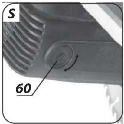
- Unscrew carbon brush covers (60) (fig. S).
- Remove worn out carbon brushes.
-
Remove any carbon dust with stream of compressed air at low pressure.
-
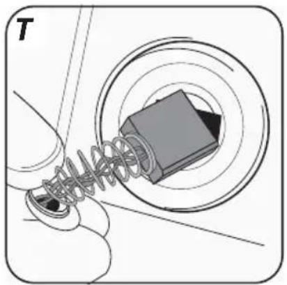
Insert new carbon brushes (brushes should easily move into brush-holders) (fig. T).
- Fix carbon brush covers (60).

After the carbon brushes are replaced, start the saw with no load and wait 1–2 minutes until the carbon brushes fit to the motor commutator. Entrust replacement of carbon brushes only to a qualified person. Use only original parts.

All defects should be repaired by service workshop authorized by the manufacturer.
TECHNICAL PARAMETERS
RATED PARAMETERS
| Flip Over Saw | |
| Parameter Value | |
| Supply voltage 230 V AC | |
| Power supply frequency 50 Hz | |
| Rated power 1600 W | |
| Cutting blade rotational speed (no load) 4800 min | -1 |
| Outer diameter of cutting blade 254 mm | |
| Inner diameter of cutting blade 30 mm | |
| Protection class II | |
| Weight 15 kg | |
| Year of production 2017 | |
| Table saw mode | ||
| Maximum thickness of cut material 38 mm | ||
| Mitre saw mode | ||
| Bevel cutting range 0^ ÷ 45^ | ||
| Mitre cutting range | ± 45^ | |
| Cutting capacity for angle / bevel cutting | 0^ × 0^ | 70 x 150 mm |
| 45^ × 0^ | 70 x 110 mm | |
| 45^ × 45^ | 40 x 110 mm | |
| 0^ × 45^ | 40 x 150 mm | |
NOISE LEVEL AND VIBRATION PARAMETERS
| Flip Over Saw | |
| Sound pressure | Lp_A = 89 dB(A) K=3 dB(A) |
| Sound power | Lw_A = 102 dB(A) K=3 dB(A) |
Noise and vibration information
Noise produced by the device is defined with: level of produced sound pressure Lp_A and level of sound power Lw_A (where K is measurement uncertainty). Vibrations produced by the device are defined with vibration acceleration value a_h (where K is measurement uncertainty).
Sound pressure Lp_A , sound power Lw_A and vibration acceleration ah specified in this manual have been measured in accordance with EN 61029. Specified vibration level a_h can be used to compare tools and for initial evaluation of exposition to vibrations.
Specified vibration level is representative for main applications of the device. When the device is used for other purposes or
with different working tools, the vibration level may change. Insufficient or too rare maintenance may increase vibration level. The abovementioned factors may lead to higher exposure to vibrations during whole working time.
To precisely define exposure to vibrations, include periods when the device is switched off and when it is switched on but not used for working. Once all factors have been carefully considered, total exposition to vibrations may be significantly lower.
To protect the user from results of exposure to vibrations, use additional safety measures such as: device and working tool periodic maintenance, proper hand temperature conditions, good work organisation.
ENVIRONMENTAL PROTECTION / CE
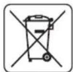
Electrical equipment must not be disposed off with household waste and, instead, should be utilized at appropriate facilities. Information on utilization can be provided by the product vendor or the local authorities. Waste electrical and electronic equipment contains substances that are not neutral to the natural environment. Equipment that is not recycled constitutes a potential hazard to the environment and to human health.
* Right to introduce changes is reserved.
"Grupa Topex Spółka z ograniczoną odpowiedzialnością" Spółka komandytowa with seat in Warsaw at ul. Pograniczna 2/4 (hereinafter Grupa Topex) informs, that all copyrights to this instruction (hereinafter Instruction), including, but not limited to, text, photographies, schemes, drawings and layout of the instruction, belong to Grupa Topex exclusively and are protected by laws accordingly to Copyright and Related Rights Act of 4 February 2004 (ustawa o prawie autorskim i prawach pokrewnych, Dz. U. 2006 No 90 item 631 with later amendments). Copying, processing, publishing, modifications for commercial purposes of the entire Instruction or its parts without written permission of Grupa Topex are strictly forbidden and may cause civil and legal liability.

MANIPULACE S VÝSUVNÝM RAMENEM (HLAVOU)
UPORABA KOT ZAJERALNA ŽAGA
DELO Z IZVLEČNO ROKO (GLAVA)

POSEBNI PROPISI O SIGURNOSTI
VIŠENAMJENSKA PILA, SIGURNOSNA UPOZORENJA
NAGIBNA PILA (ELEMENTI)
- Drška rukohvata
- Poluga blokade pomičnog štitnika
- Pomični štitnik
- Granični rubnik
- Gumb za blokadu ramena okomite stezaljke
- Okomita stezaljka
- Kotačić za blokadu okomite stezaljke
- Poluga za blokadu nagiba glave
- Svornjak za blokadu glave
- Produžni mehanizam okretnog stola
- Vijak za blokadu produžnog nastavka stola
- Okretni stol
- Kutna skala za okretni stol
- Uložak okretnog stola
- Gumb za blokadu okretnog stola
- Kotačić za blokadu okretnog stola
-
Nastavak za odvod prašine
-
Graničnik
-
Vijak za podešavanje
-
Kontra matica
-
Kutna skala nagiba glave
-
Vijak za podešavanje kuta 90°
-
Matica
-
Vijak za podešavanje kuta 45°
-
Matica
-
Vijak
-
Poklopac
-
Vijak za pričvršćivanje lista pile
-
Vanjska prirubnica
-
Poklopac ugljene četkice
* Moguće su razlike između crteža i proizvoda.
OPIS KORIŠTENIH GRAFIČKIH ZNAKOVA

POZOR

UPOZORENJE

MONTAŽA/POSTAVKE

INFORMACIJA
DIJELOVI I DODATNA OPREMA
-
Okomita stezaljka
-
Podesivi kutomjer + poprečna vodilica - 1 kom.
-
Paralelna vodilica
-
Posuda za odvod iverja - 1 kom.
-
Potiskivač
- 1 kom..
- 1
- 1
PRIPREMA ZA RAD

Prije početka svih radova na montiranju ili podešavanju pile, provjerite da li je pila isključena iz napajanja.
MONTIRANJE VIŠENAMJENSKE PILE NA RADIONIČKI STOL

AFVOEREN VAN HET STOF

AFVOEREN VAN HET STOF

- INSTRUKCJA ORYGINALNA (OBSŁUGI)
- PILARKA UNIWERSALNA 59G801
- SZCZEGÓŁOWE PRZEPISY BEZPIECZEŃSTWA
- PILARKA UNIWERSALNA, OSTRZEŻENIA DOTYCZĄCE BEZPIECZEŃSTWA
- DETAILED SAFETY REGULATIONS
- SAFETY WARNINGS FOR FLIP OVER SAW
- Safety conditions for flip over saw
- CAUTION! This device is designed to operate indoors.
- CONSTRUCTION AND USE
- Use the tool only in accordance with its purpose.
- DESCRIPTION OF DRAWING PAGES
- TABLE SAW (ITEMS)
- MITRE SAW (ITEMS)
- MEANING OF SYMBOLS
- TRANSPORT
- INSTRUCTIONS FOR CUTTING
- USE IN TABLE SAW MODE
- DUST EXTRACTION
- CHECKING POSITION OF THE RIVING KNIFE
- CUTTING BLADE GUARD
- RIPPING FENCE INSTALLATION
- SWITCHING ON / SWITCHING OFF
- CUTTING DEPTH ADJUSTMENT
- MITRE CUTTING WITH USE OF THE MITRE GAUGE
- RIPPING
- CUTTING SMALL OBJECTS
- USE IN MITRE SAW MODE
- USING THE EXTENSION ARM (HEAD)
- VERTICAL CLAMP
- INSTALLATION AND REMOVAL OF THE TURNTABLE EXTENSIONS
- CHECKING AND ADJUSTMENT OF CUTTING DEPTH
- Switching on
- Switching off
- CUTTING OFF NARROW PIECES OF MATERIAL
- SETTING THE TURNTABLE FOR MITRE CUTTING
- SETTING THE EXTENSION ARM (HEAD) FOR BEVEL CUTTING
- CHECKING AND ADJUSTMENT OF PERPENDICULAR POSITION OF CUTTING BLADE AND TURNTABLE
- CLEANING
- CUTTING BLADE REPLACEMENT
- REPLACEMENT OF CARBON BRUSHES
- TECHNICAL PARAMETERS
- Noise and vibration information
- ENVIRONMENTAL PROTECTION / CE
- MANIPULACE S VÝSUVNÝM RAMENEM (HLAVOU)
- UPORABA KOT ZAJERALNA ŽAGA
- DELO Z IZVLEČNO ROKO (GLAVA)
- POSEBNI PROPISI O SIGURNOSTI
- VIŠENAMJENSKA PILA, SIGURNOSNA UPOZORENJA
- NAGIBNA PILA (ELEMENTI)
- OPIS KORIŠTENIH GRAFIČKIH ZNAKOVA
- DIJELOVI I DODATNA OPREMA
- PRIPREMA ZA RAD
- MONTIRANJE VIŠENAMJENSKE PILE NA RADIONIČKI STOL
- AFVOEREN VAN HET STOF
Brand : Graphite
Model : 59G801
Category : Saw