
YT-85550 - Tractor Yato - Free user manual and instructions
Find the device manual for free YT-85550 Yato in PDF.

| Product type | Gasoline lawn tractor |
| Brand | Yato |
| Model | YT-85550 |
| Engine | 4-stroke, 1 cylinder, 432 cc, 8.8 kW, air cooled |
| Fuel | Unleaded gasoline E10 (octane rating ≥ 95) |
| Engine oil | SAE 15W-40, capacity 0.9 L |
| Starting | Electric |
| Battery | Lead, 12 V, 18 Ah |
| Cutting width | 760 mm |
| Cutting height | Adjustable from 20 to 90 mm (6 positions) |
| Grass collector capacity | 170 L |
| Wheel diameter | Front 10" (254 mm), Rear 15" (381 mm) |
| Weight | 174 kg |
| Sound level | Pressure 78.8 dB(A), Power 100.4 dB(A) |
| Vibration level | Hands 4.74 m/s², Whole body 0.64 m/s² |
| Safety | Operator presence sensor, parking brake, mulching cover |
| Maintenance | Oil change every 25h, air filter cleaning, spark plug replacement every 100h, blade replacement every 2 years or 50h |
| Included accessories | Grass collector, side discharge, mulching (assembly required) |
| Assembly | Requires assembly before first use (seat, steering wheel, battery, grass collector) |
| Warranty | Manufacturer warranty (refer to manual) |
Frequently Asked Questions - YT-85550 Yato
User questions about YT-85550 Yato
0 question about this device. Answer the ones you know or ask your own.
Ask a new question about this device
Download the instructions for your Tractor in PDF format for free! Find your manual YT-85550 - Yato and take your electronic device back in hand. On this page are published all the documents necessary for the use of your device. YT-85550 by Yato.
USER MANUAL YT-85550 Yato

PL EN DE RU UA LT LV CZ SK HU RO ES FR IT NL GR BG PT HR AR

PL EN DE RU UA LT LV CZ SK HU RO ES FR IT NL GR BG PT HR AR
flowchart
graph TD
    A["Start"] --> B{Loop 1}
    B --> C{Loop 2}
    C --> D{Loop 3}
    D --> E{Loop 4}
    E --> F{Loop 5}
    F --> G{Loop 6}
    G --> H{Loop 7}
    H --> I{Loop 8}
    I --> J{Loop 9}
    J --> K["End"]
    style A fill:#000,stroke:#000,color:#fff
    style K fill:#000,stroke:#000,color:#fff
    style B fill:#fff,stroke:#000
    style C fill:#fff,stroke:#000
    style D fill:#fff,stroke:#000
    style E fill:#fff,stroke:#000
    style F fill:#fff,stroke:#000
    style G fill:#fff,stroke:#000
    style H fill:#fff,stroke:#000
    style I fill:#fff,stroke:#000
    style J fill:#fff,stroke:#000
    style K fill:#fff,stroke:#000
    style_L["XXVI"] at bottom right corner
flowchart
graph TD
    A["Start"] --> B["Process Step 1"]
    B --> C["Process Step 2"]
    C --> D["Process Step 3"]
    D --> E["End"]
PL EN DE RU UA LT LV CZ SK HU RO ES FR IT NL GR BG PT HR AR
natural_image
Mechanical assembly diagram showing a hand operating a tool with a circular arrow indicating rotation (no text or symbols present)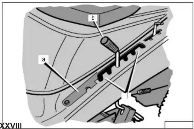
PL EN DE RU UA LT LV CZ SK HU RO ES FR IT NL GR BG PT HR AR
natural_image
Technical line drawing of a vehicle chassis with four wheels and suspension components (no text or symbols)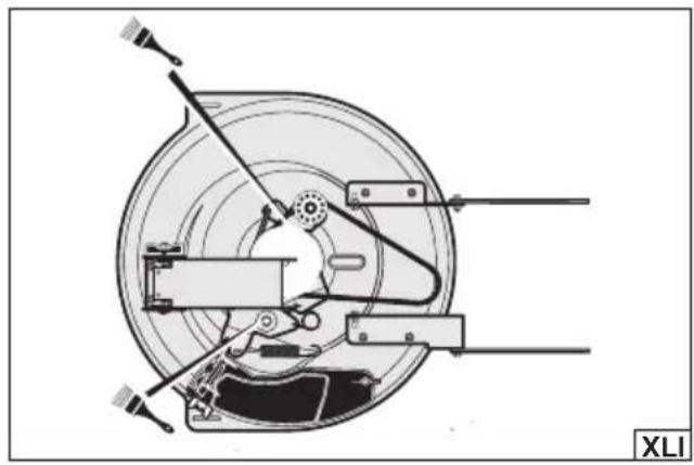
natural_image
Technical diagram of a mechanical assembly with labeled components (no readable text or symbols)PL
- seat
- seat base
- steering wheel
- steering column cover
- wheel
- grass catcher
- mower housing
- engine
- mulching cover
DE
Read the operating instruction
Attention - Do not touch the rotating blade!
Beware of ejected objects.
Danger – Do not operate the mower without the entire grass catcher or blade guard in place
natural_image
Two pictograms showing a person falling on a slope and another person sitting on a platform with boxes, labeled '21 XAM' (no text or symbols in the diagrams)Stay away from bystanders
The tractor – petrol mower is powered by a combustion engine. The mower is operated by the operator sitting on the machine. The machine is used to cut grass on lawns of considerable size. The adjustable grass cutting height allows for versatile use. Proper, reliable and safe operation of the appliance depends on appropriate use, that is why you should
Read this entire manual before the first use of the machine and keep it for future reference.
The supplier shall not be held liable for any damage or injury resulting from improper use of the machine, failure to observe the safety regulations and recommendations of this instructions manual. Using the machine for purposes other than those for which it was intended shall cause the loss of the user's rights to a warranty and statutory warranty.
ACCESSORIES
The mower is supplied complete but requires assembly before first use.
SPECIFICATIONS
| Parameter Unit Value | ||
| Part No. YT-85550 | ||
| Number of cylinders 1 | ||
| Number of strokes 4 | ||
| Fuel type E10 unleaded petrol | ||
| Type of oil SAE 15W-40 | ||
| Engine capacity [cm] | ^3 ] 432 | |
| Maximal power [kW] 8.8 | ||
| Maximum engine revolutions | [min ^1 ] | 3600 |
| Cooling | Air cooling | |
| Type of starting | Electric | |
| Fuel tank capacity | [I] | 4.2 |
| Oil tank capacity [I] | 0.9 | |
| Sparking plug type | RC12YC | |
| Air filter type | T381 | |
| Battery type | Lead acid | |
| Rated battery voltage | [V] | 12 |
| Battery capacity | [Ah] | 18 |
| Maximum grass cutting width | [mm] 760 | |
| Diameter of front, back wheels | ["/mm] | 10"/254, 15"/381 |
| Grass catcher capacity | [I] | 170 |
| Mowing height | [mm] | 20 – 90 |
| Weight | [kg] | 174 |
| Hand-to-hand vibration level | [m/s 12 ] | 4.74 ± 1.5 |
| Whole-body vibration level | [m/s 12 ] | 0.64 ± 1.5 |
| Noise level | ||
| sound pressure | [dB(A)] | 78.8 ± 3 |
| sound power | [dB(A)] | 100.4 ± 2.03 |
SAFETY INSTRUCTIONS
IMPORTANT! PLEASE READ THESE INSTRUCTIONS CAREFULLY BEFORE USE KEEP FOR FUTURE REFERENCE
Instructions
Read the manual carefully. Familiarise yourself with the controls and proper use of the machine. If the machine is passed on to another person, the operating instructions must be included. Always use the machine in accordance with the guidelines in the manual.
Do not allow children or anyone not familiar with the machine instructions to operate the machine.
Never mow when anyone else, especially children or pets, is around. Before starting work, designate a safety zone within which
EN
bystanders and pets will not be allowed. A space with a radius of at least five metres must be maintained from the working mower. Remember that it is the operator or the user who is responsible for accidents or hazards to other people or the environment.
Preparation
Always wear sturdy footwear and long trousers when working, and do not work with bare feet or in sandals.
Personal protective equipment such as safety goggles and ear defenders should be used during work. The use of personal protective equipment such as dust masks, eye protection, slip-resistant safety shoes, helmets and hearing protectors reduce the risk of serious personal injuries.
Keep hair, clothing and work gloves away from moving parts of the machine. Loose clothing, jewellery or long hair can catch on moving parts of the machine and be caught, which can cause serious injury.
Avoid wearing damaged clothing which is too loose or has hanging straps or ribbons. Loose clothing parts can be caught by the machine moving parts which can lead to injuries.
Before starting work, inspect the area where the device will be working carefully and remove any stones, branches, wires, bones, toys and other foreign objects. Caught objects can cause damage to the machine, or can be ejected at high speed, which poses a threat to the operator and the environment.
Before turning on the machine, remove any spanners and other tools that have been used to adjust it. A spanner left on rotating parts of the machine can lead to serious injury.
Check the area thoroughly before mowing. Working in unfamiliar territory can lead to dangerous situations. Do not work on uneven, potholed or bumpy terrain. Pay attention to protruding roots. Tall grass can hide bumps and obstacles. Uneven or bumpy terrain can lead to the machine tipping over with the operator, resulting in serious injury or even death.
Always check the blades and fixing screws for wear or damage before use. Replace worn blades and screws before starting work.
Check also whether the screw connections are not loose. Tighten the loose screws.
Operation
WARNING! Do not operate the machine indoors or in confined space where vapours of dangerous carbon monoxide may accumulate. Fuel fumes and vapours are toxic. Intoxication can lead to accidents and cause serious injury or even death.
Do not work while tired or under the influence of medication, alcohol or drugs. Even a moment's distraction while working can lead to serious personal injury.
Mow only in daylight or in good artificial lighting.
Do not mow in the rain. If possible, avoid mowing wet grass.
WARNING! Do not operate the machine when there is a risk of lightning.
Take special care when working on slopes and when changing direction on a slope. Do not suddenly change direction or speed when driving on slopes. Do not mow on excessively inclined slopes. Ensure that it is safe to operate the machine when driving on a slope. When driving on a slope, move slowly. When mowing on slopes, move up or down the slope, never across. Do not move or stop on the slope. If traction is lost on a slope, switch off the blade drive and then steer the machine slowly while moving down the slope. Never exceed the maximum permissible working angle on slopes.
The engine must be switched off if the machine is to be tilted when moving it over surfaces other than grass and when being transported to and from the mowing area.
Ensure that all interlocks and operator presence controls on the stand are working properly.
Do not use the mower without the complete grass catcher in place or the self-closing guards in the ejection opening.
Start the engine as instructed, ensure that the feet are away from the blades.
Keep hands and feet away from rotating parts. Keep an eye on the ejection port at all times to ensure that it is not blocked.
Stop the mower engine:
- each time an operator needs to leave his post
- before refuelling or topping up engine oil
- before cleaning the outlet
- before cleaning, checking, replacing accessories or repairing the machine
- before dismantling the grass catcher
- after it being hit by a foreign object. Check the mower for damage and repair if necessary before restarting it
- if the device starts to vibrate excessively (check immediately)
ATTENTION! After the engine is switched off, the blade continues to spin for some time. Wait for the blade to stop.
If the machine starts to vibrate excessively:
- check for damage,
- replace or repair any defective part,
- check and tighten loose parts.
Maintenance and storage
WARNING! Disconnect the spark plug before adjusting, changing accessories or storing the machine. This will allow for avoiding accidental turning on of the machine.
Allow the machine and all its components to cool completely before carrying out maintenance.
Keep all nuts, bolts and screws in good condition to ensure safe device operation.
EN
Do not store the mower with fuel in the tank.
Ensure that the storage area is away from fire sources.
Check the grass catcher frequently for wear or damage.
Always wear safety goggles when adjusting, maintaining and repairing the machine.
Replace worn or damaged parts to ensure safety.
Use caution when adjusting the machine to avoid fingers getting between its moving blades and fixed parts.
Do not change the sealed engine speed settings. Changing the factory engine speed settings can lead to damage to the machine or even a fire.
Regularly check that all start interlocks and operator presence controls are working properly. Improper operation of the machine's guards and safety components can cause accidents.
Maintain the mower regularly and keep it clean and in good working condition.
Do not disconnect or modify the machine guards. Improper operation of guards can cause accidents.
Use original spare parts and equipment only. The use of unsuitable equipment can lead to damage to the machine and/or serious injury.
Ensure that the correct type of blades are used.
ADDITIONAL SAFETY INSTRUCTIONS
Recommended fuel, unleaded petrol E10, with an octane number of at least 95.
Use four-stroke engine fuel and oil which are free from solid impurities. Premium quality products are recommended. They will extend the service life of the engine.
Check the oil level in the engine regularly. Operating the mower with too low or no oil level can lead to damage and even fire.
Ensure that the mower is properly assembled before starting work.
Do not expose the machine to moisture. Do not use the mower during precipitation or when there is a risk of lightning. Do not use the mower in a humid and wet environment.
Before using the machine, it is recommended to ask your dealer or specialist to demonstrate how to use it safely and effectively.
Do not modify the machine in any way. Do not use substitutes for blades other than the original.
Always start operation wearing work clothing, gloves, full footwear and safety glasses protecting against mechanical hazards.
If during work the operation of the mower seems suspicious (increased vibration, noise, odour, etc.), it should be immediately turned off and handed over to a repair centre.
After replacing the blade, ensure that the blade rotates freely and without obstruction before restarting the mower. The blade must be carefully balanced before installation.
For repairs and maintenance use only original spare parts.
The engine ventilation openings must be kept clear at all times.
Do not run the mower in enclosed or unventilated areas. The exhaust gases contain substances that are harmful to health and must not be inhaled.
The fuel feed system must be checked periodically. If you notice leaks, have the unit repaired by an authorised servicing centre.
Wait until the engine has reached its rated speed before mowing.
Do not cover the ventilation inlets and outlets Even when the mower is not running.
Before transporting the mower, it is necessary to empty the fuel tank.
Do not touch the engine surfaces that become hot during operation. This may cause burns.
The fuel is highly flammable! Do not fill the fuel tank during operation or when the machine is hot. Refuel outdoors. Do not refuel near an open flame. Do not spill fuel. In the event of a fuel spillage, dry up the spilled fuel thoroughly before starting the mower. Tighten the fuel filler cap firmly and securely.
If you leave the mower unattended, stop the machine, switch off the blade drive, move the gearshift lever to the neutral position marked "N", set the parking brake, then stop the engine and remove the ignition key.
Do not allow the grass catcher to overflow. The grass catcher should be emptied regularly.
When finished working, remove the ignition key and disconnect the spark plug wire to prevent bystanders from using the machine.
Do not modify the engine or other mechanisms of the mower in any way.
Do not operate the mower without the air filter correctly fitted.
MOWER ASSEMBLY
Preparation for assembly
Unpack the product by removing all packaging components. It is recommended to retain the packaging, which can be of use when transporting or storing the product.
Check that no part of the product has been damaged during transport. In case of damage detection, such as cracks or deformations, it will disqualify the product from further use until it is repaired or damaged components are replaced.
It is advisable to place the machine on a flat, hard and clean surface.
Use personal protective equipment such as protective gloves, eye protection, and protective clothing during assembly.
EN
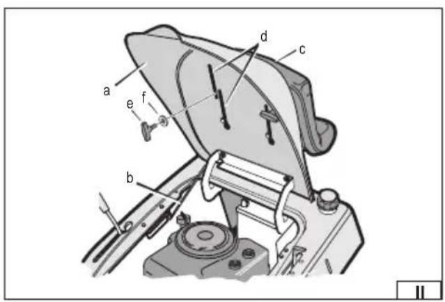
Assembly, seat adjustment (II)
Open the seat base (a) completely by grasping the handle and then secure its position with the posture holder support rod (b). Slide the lower seat hooks (c) into the rear holes of the guides (d) in the seat base (a), then lock the seat position (c) in the guides (d) with wing nuts (e) and washers (f). It is advisable to adjust the seat position appropriate to the operator's height once all the machine components have been completed. To adjust the distance of the seat from the steering wheel, loosen the wing nuts and then move the seat forwards or backwards. Lock the seat position by tightening the wing nuts. Ensure that the nuts are tightened firmly and securely and that the seat does not change its position during operation. Once the assembly or adjustment of the seat has been completed, unlock the rod holding the base handle and then close the seat base to the working position.
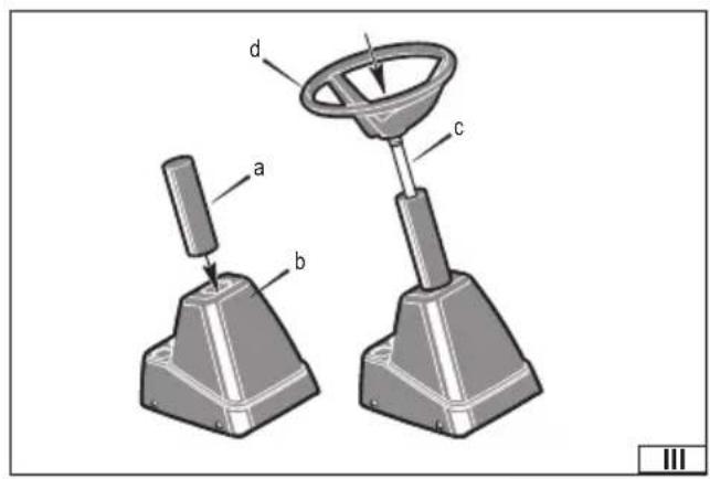
Steering wheel assembly (III)
Before fitting the steering wheel, ensure that the front wheels are aligned to the direction of travel straight ahead. Slide the column cover (a) into the hole located in the console (b). Ensure that the end of the column guard fits into the steering bushing. Slide the steering column (c) together with the steering wheel (d) into the hole located in the column cover and then push in the steering wheel. The steering wheel should lock into the pinion wheel. Pull on the steering wheel to ensure that its position is correctly locked in its mount and will not slip out during operation.
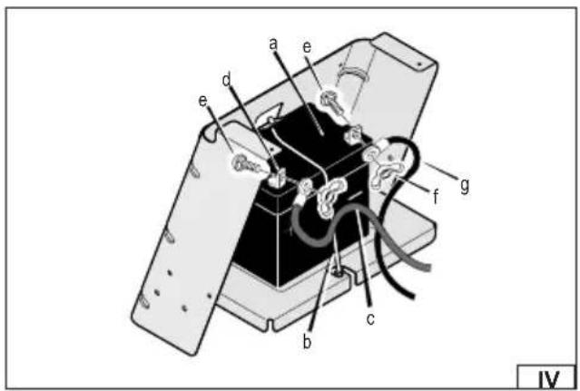
Connecting the battery (IV)
ATTENTION! Before fitting the battery, switch off the engine, allow all machine components to cool completely and then disconnect the spark plug wire.
ATTENTION! Special care must be taken during battery installation/removal operations to ensure that the terminals are not short-circuited.
To install the battery, open the seat base completely by grasping the handle and then secure its position with the posture handle support bar. Place the battery (a) in the base and then secure it to the base with the bracket (b) as shown in the figure (IV), so that the bracket locks into the top and then the bottom catch. Connect the cable terminal to the battery terminal in the following order: Connect the terminal of the red cable (c) to the battery terminal (d) marked “+” and fix with the screw (e) and wing nut (f), then secure with the protective cap.
Connect the black cable terminal (g) to the battery terminal (h) marked “-” and fix with the screw (e) and wing nut (f), then secure with the protective cap.
Once the battery has been installed, unlock the rod holding the base bracket and then close the seat base to the operating position.
Installation/removal of grass catcher
ATTENTION! If it becomes necessary to fit or remove accessories during operation, always stop the machine, switch off the blade drive, move the gearshift lever to the neutral position marked "N", set the parking brake, then stop the engine and remove the ignition key.
Allow all components to cool completely, then disconnect the spark plug wire.
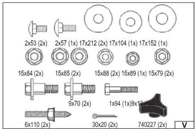
See figure (V) for a description of the parts needed to assemble the grass catcher.
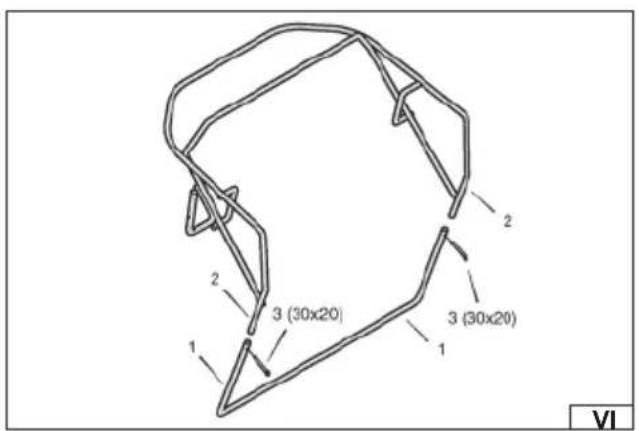
The installation of the grass catcher is shown in the figures:
(VI) – Slide the lower part of the catcher frame (1) onto the upper part of the frame (2), align the holes of the two parts, insert the pins (3) into the holes and then secure the connection by bending both legs of each pin.
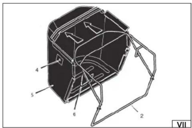
(VII) – First place the cutout (4) located on the right side of the catcher cover (5) near the handle bracket (6). Then slide the catcher cover (5) onto the frame (2).
(VIII) – Place the cover clamps (7) on the frame (2).
(IX) - Fasten the handle (8) to the handle bracket (6) with the screw (9) and nut (10).
The installation of the bracket that allows the grass catcher to be fitted to the machine is shown in the following figures:
(X) – Screw the two screws (11) into the rear mounting bracket (12), screw on the nuts (13) and then tighten the nuts. Remove the two screws at the bottom of the handle (12), replace them with studs (14) and then secure with nuts (18). The shorter threads of the screws (14) should be attached to the rear bracket (12). Remove the plastic cover (17) from the rear bracket (12).
(XI) – Align the holes (15) located in the catcher mounting plate with the upper bolts (11) of the rear mounting bracket on the machine, then press the catcher mounting plate against the rear mounting bracket and push down so that the bolts (11) lock into the holes (15) of the catcher mounting plate. Secure the lower part of the catcher fixing plate to the threads (14) using the knobs (16).
The method of fitting the grass catcher cover is shown in the figure (XII).
Insert the left end of the hinge rod (3) into the left opening of the cover (2) and then push the cover (1) to the right. Insert the right end of the hinge rod (3) into the right-hand hole of the lid (4), then slide the lid to the left so that the right end of the hinge rod (4) is in the right-hand hole of the lid (4). Fix the spring (7) holding the cover in the closed position to the cover mounting hole (1) using the fi xing screw (6), washer (5) and nut (8).
Note! Take care when fitting the spring holding the cover. Secure hands to avoid injury.
EN
The installation of the rear ejection duct is shown in the figures:
(XIII) – Unscrew the wing nuts (1) from the blade guard (2). Lift the mulching cover (3), fit the first part of the rear ejection duct (4) to the blade guard and then secure with the wing nut (1).
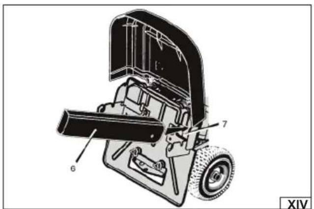
(XIV) – Insert the straight end of the second part of the rear ejection tube (6) into the hole of the catcher fixing plate (7). Ensure that the warning symbol is visible on the outside of the cable (6).
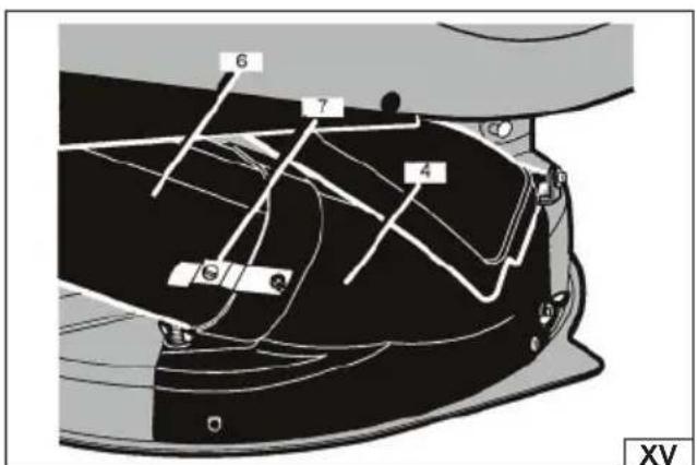
(XV) – Insert the end of the second part of the rear ejection duct (6) into the first part of the duct (4). Insert the fixing clamp holder (7) into the hole of the second part of the cable (6).
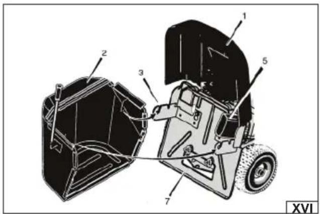
The method of fitting the grass catcher to the mower is shown in the figure (XVI).
Lift and hold the grass catcher cover (1) in the upper position. Place the grass catcher (2) in the handle slots (3) on the catcher mounting plate. Ensure that the grass catcher (2) is correctly mounted and positioned. Lower the grass catcher lid (1).
The installation of the handle attachment extension and the grass catcher plate baffle are shown in the figure (XVII).
Place the handle clip extension (1) on top of the rear handle (2) and the catcher plate baffle (8) on the underside of the rear handle (1). Use two bolts (3), washers (9) and two nuts (4). Be sure to place the washers (9) and nuts (4) under the catcher plate baffle (8). Secure the centre of the handle extension (1) with a bolt (5), washer (6) and nut (7). Tighten the fixing nut.
Recommendations for final assembly:
Check all fasteners. Ensure that all fasteners are properly assembled and tight.
Check assembly. Ensure that all parts are correctly assembled.
Note! Ensure that the grass catcher is properly assembled and correctly installed. The grass catcher must only be used when fully assembled and correctly installed in the machine handles.
Disassemble the grass catcher based on the following figures:
(XVI) – Lift the grass catcher cover (1) and then pull the grass catcher (2) from the handles.
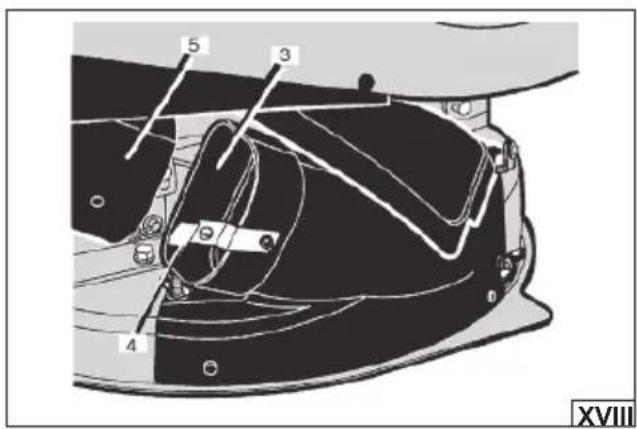
(XVIII) – Disconnect the fixing clamp (4) from the other part of the rear ejection cable (5).
(XVI) - Pull the second part of the rear ejection tube (5) out of the hole of the catcher fixing plate (7).
(XI) – Unscrew the two knobs (16) located at the bottom of the catcher fixing plate (15). Remove the grass catcher fixing plate (15) by sliding it upwards and then removing it from the screws (11).
(XIII) Unscrew the wing nuts (1) securing the first part of the rear ejection tube (4). Lift the mulching cover (3) and then pull out the first part of the rear ejection duct (4). Close the mulching cover (3) and then secure it to the blade guard (2) with the wing nut (1). (X) Cover the rear ejection window located in the rear handle of the machine with the plastic cover (17).
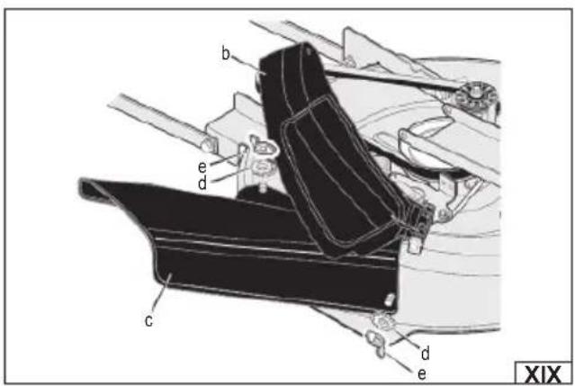
Side ejection assembly (IX)
ATTENTION! If it becomes necessary to fit or remove accessories during operation, always stop the machine, switch off the blade drive, move the gearshift lever to the neutral position marked “N”, set the parking brake, then stop the engine and remove the ignition key.
Allow all components to cool completely, then disconnect the spark plug wire.
The installation of a side discharge guard allows the machine to be prepared to spread grass cuttings along the path of the mower. Grass cuttings left on the lawn can be used as a natural fertiliser.
If a grass catcher is fitted to the machine, remove it as described above. The installation of the side ejection is shown in the figure (XIX). Unscrew the wing nut (a) securing the mulching cover (b). Lift the mulching cover (b). Place the side ejection guard (c) in the mountings, then fix with washers (d) and wing nuts (e). Ensure that the rear ejection window located in the rear handle of the machine is covered with a plastic cover.
Installing the mulching cover
ATTENTION! If it becomes necessary to fit or remove accessories during operation, always stop the machine, switch off the blade drive, move the gearshift lever to the neutral position marked "N", set the parking brake, then stop the engine and remove the ignition key. Allow all components to cool completely, then disconnect the spark plug wire.
Note! The mulching cover is a safety feature of the machine. Do not remove the mulching cover. The mulching cover forces the grass cuttings to spread towards the ground. If a side ejection guard or grass catcher with rear ejection duct is not fitted to the machine, ensure that the mulching cover is in place and correctly fitted before starting work.
The mulching cover allows the grass to be mulched. Mulching involves cutting the grass, shredding it and then leaving it on the lawn as a natural protective layer. If a grass catcher and rear ejection cable is fitted to the machine, it must be removed as described earlier in this manual; if a side ejection is fitted to the machine, it must be removed in reverse to the installation described above. Place the mulching cover in position, then fasten and secure with a washer and wing nut. Cover the rear ejection window located in the rear handle of the machine with a plastic cover.
OPERATING THE MOWER
Preparing for operation
ATTENTION! At the factory, the engine may only contain a small amount of oil to protect the engine during transport and storage. Check the oil level in the engine before the first start-up and top up the oil to the required level.
Prepare oil for four-stroke engines in viscosity class SAE 15W40.
Before replenishing the oil, place the machine on a flat surface, then unscrew the oil tank cover and wipe the oil bayonet attached to it dry. Fill the tank with oil. When filling, it is recommended to use a funnel or filler nozzle to avoid spilling oil. In case of spilling the oil, thoroughly wipe off its residues before starting the engine. Check that the level is appropriate. To do this, insert the bayonet into the inlet and screw the tank cover. Then unscrew it and check the oil level on the bayonet. The oil level should be between the maximum and minimum levels on the bayonet (XXXI). After making sure that the oil level is correct, close the inlet with a cap. ATTENTION! Check the oil level before each use. Never check the oil level while the engine is running.
After refilling oil, refill fuel. Use 95-octane unleaded petrol or better. To refuel, unscrew the fuel tank cover and pour the fuel into the tank. When filling fuel, it is recommended to use a filler nozzle or funnel to reduce the risk of fuel splashes. If the fuel is splashed, thoroughly wipe off its residues. Wait until the vapours have completely evaporated and carry out the start-up at a different place than at which the fuel was filled. Close the fuel tank inlet with the cover after filling.
The mower is equipped with inflatable wheels. The recommended tyre pressure is 14 psi/1.0 bar. Inflate the tyres before starting work. Do not exceed the recommended tyre pressure. Tyres should always be inflated to an even pressure level. Incorrect or uneven tyre pressure can cause uneven mowing and lead to dangerous situations such as the machine tipping over on its side, which can cause serious injury or even death.
ATTENTION! Check tyre pressure each time before starting work.
Before starting work, check that the machine is not damaged, is correctly assembled and that all safety components are correctly attached. If the machine is found to be incomplete or damaged, further work is prohibited!
Clear the work area of all visible stones, roots, wires, toys and other obstacles that can be picked up by the machine blades and thrown in a different direction. Particular attention must be paid to electrical cables to ensure that they do not enter the work zone. Leaving electrical cables in the work area can lead to damage to the wires, resulting in electric shock and even death.
Mower controls
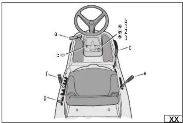
The figure (XX) shows the controls of the mower:
a. clutch/brake pedal – functions as a clutch as well as a brake.
b. ignition switch - used to start and stop the engine with the key in three positions: start (3), run (2), off (1).
c. parking brake – used to immobilise the machine when stationary.
d. blade drive lever – used to start or stop the blade drive.
e. gear shift lever – allows selection of the drive train ratio.
f. mowing height adjustment lever – allows the mowing height to be set.
g. throttle control lever – allows the engine speed to be increased or decreased.
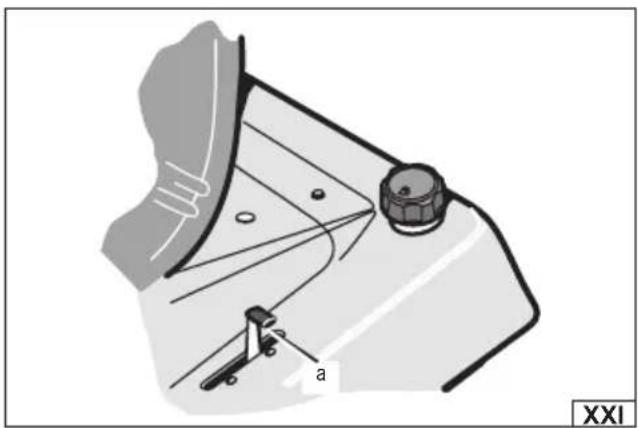
How to use the throttle control lever (XXI):
To start the cold engine, push the throttle lever (a) fully forward into the position marked with the choke symbol.
During normal operation and when mowing grass with the grass catcher fitted, increase the engine speed by moving the throttle lever (a) to the position marked with the hare symbol. To charge the battery and keep the engine running cooler, move the throttle lever (a) to the position marked with the hare symbol.
The maximum engine speed that can be set with the throttle lever is set at the factory to the maximum engine performance. Do not change the sealed engine speed settings. Increasing the factory-set engine speed can lead to damage to the machine's engine or even a fire.
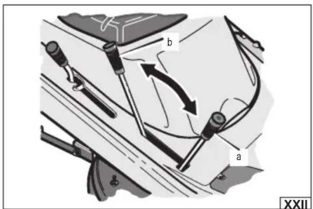
How to use the blade drive lever (XXII):
ATTENTION! Before starting the engine, ensure that the blade drive is switched off, the blade drive lever is in the STOP position. To start the blade drive, move the blade drive lever to the on position (a) – START. Starting the blade drive will cause the blades to rotate. To stop the blade drive, move the blade drive lever to the off position (b) – STOP. Switching off the blade drive will cause the blades to stop.
ATTENTION! The blades can still rotate a few seconds after the blade drive is switched off.
Warning! Always keep hands and feet away from rotating blades, the ejection port and moving engine parts. Always switch off the blade drive and ensure that the blade has stopped rotating before leaving the stand. Always switch off the blade drive before driving the machine on the pavement or road.
How to use the gearshift lever:
ATTENTION! Bring the machine to a complete stop before changing gear. To do this, press the clutch/brake pedal (a) forward.
Changing gears while driving can damage the gearbox.
Note! Make sure the area around the machine is clear of obstructions and bystanders before setting the reverse gear and starting to drive backwards. Do not turn near walls of buildings, trees or other fixed obstacles to avoid dangerous situations.
EN
To change the forward speed of the machine or to change the direction of travel, follow the instructions as shown in the figures:
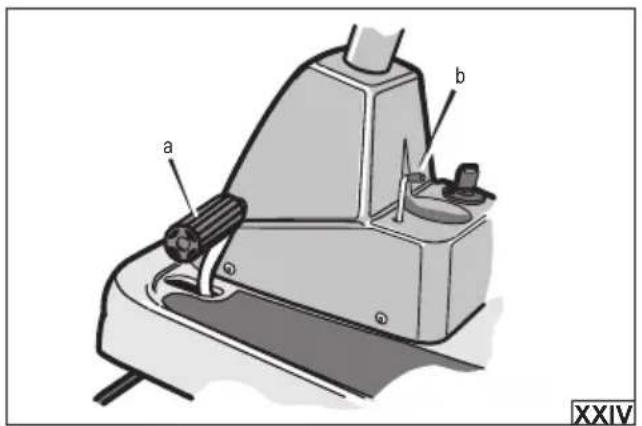
(XXIV) - Stop the machine by pressing the clutch/brake pedal (a) fully forward and hold it in this position.
(XXI) – Reduce engine speed by moving the throttle lever (b) to the position marked by the turtle symbol.
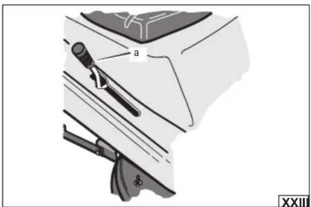
(XXIII) – To drive forward, move the gearshift lever (a) to one of the five positions. The position marked ‘1’ indicates the lowest forward speed, while the position marked ‘5’ indicates the highest forward speed. To drive in reverse, move the gearshift lever (c) to the position marked “R”.
In the next step, slowly release pressure on the clutch/brake pedal (a) once the correct gear has been set. Do not keep your foot on the pedal while driving.
(XXI) – Increase engine speed by moving the throttle lever (b) to the position marked by the hare symbol.
The table below shows the recommended shift lever position for the type of work being carried out:
| Shift lever position Work performed Throttle position | |
| 1 Grass mowing | |
| 1 or 2 Grass catching | |
| 1 or 2 Mulching | |
| 2 or 3 Normal movement | |
| 3 or 4 Easy movement | |
| 4 or 5 Transportation |
How to use the parking brake (XXIV):
To immobilise the machine when stationary, fully depress the clutch/brake pedal (a) and then lift up the parking brake lever (b). Fully release the clutch/brake pedal (a) and then release the parking brake lever (b). Ensure that the parking brake is applied and that the machine does not change its position when stationary. To release the parking brake, fully depress the clutch/brake pedal (a). The parking brake will automatically be released.
Warning! Before leaving the seat, stop the machine, switch off the blade drive, move the gearshift lever to the neutral position marked "N", set the parking brake, then stop the engine and remove the ignition key.
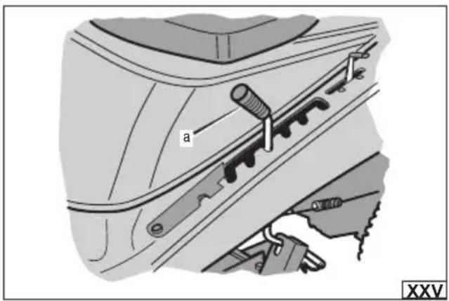
How to change the mowing height (XXV):
The mowing height is changed by changing the position of the mowing height adjustment lever (a). Setting the lever to the position marked '1' will set the minimum cutting height, while setting the lever to the position marked '6' will set the maximum cutting height. It is possible to set the cutting height at one of the 6 levels within the range shown in the technical data table.
Note! Before driving the mower on the road or pavement, set the maximum cutting height and switch off the blade drive.
Starting the combustion engine
WARNING! The mower's electrical system is equipped with an operator presence detection system. A sensor built into the seat will stop the engine if the operator leaves the seat while the blade drive is engaged or a gear is set in either direction of travel. For safety reasons, make sure this system is working properly before starting work.
Push the clutch/brake pedal fully forward and hold it in this position.
Move the gearshift lever to the neutral position marked "N".
Make sure that the blades' drive lever is in the upper position.
Push the throttle lever fully forward to the position marked with the choke symbol.
Place the key in the ignition switch. Turn the key to the start position marked – START and hold it in this position. Release pressure on the key immediately after starting the engine.
As the engine warms up, move the throttle lever to a position between the hare symbol for faster revs and the tortoise symbol for slower revs. Allow the engine to start running smoothly every time you reposition the throttle lever. The rate at which the throttle lever should be reversed depends on the ambient temperature in which you start the engine. The lower the ambient temperature, the slower the lever should be reversed. Allow the cold engine to run for a few minutes. Start work when the engine is warm.
Mowing
Use the height adjustment lever to set the mowing height.
Reduce engine speed by moving the throttle lever to the position marked by the turtle symbol.
Slowly move the blade drive lever to the on - START position.
Push the clutch/brake pedal fully forward and hold it in this position.
Use the gearshift lever to set the correct speed for the type of work being carried out. When mowing tall or dense grass or mowing with harvesting into a grass catcher, it is recommended to set the lowest speed.
Slowly release the clutch/brake pedal.
EN
Increase engine speed by moving the throttle lever to the position marked with the hare symbol.
If it is necessary to increase or decrease the driving speed during mowing, stop the machine completely, set a different driving speed and then continue working.
After cutting a small piece of grass, check the working area and make sure that the cutting height level is correct. If uneven mowing is noticed, the blade housing should be levelled as recommended in the section of the instructions "Levelling the blade housing".
Before driving the mower to another mowing area:
First stop the machine by depressing the clutch/brake pedal.
Move the blade drive lever to the off - STOP position.
Use the height adjustment lever to set the maximum cutting height.
Move the throttle levers to a position between the hare symbol for faster revs and the tortoise symbol for slower revs.
To increase speed, stop the machine by depressing the clutch/brake pedal. Use the gearshift lever to change the speed setting to a higher gear and then continue driving.
Stopping the engine
Stop the machine following below steps:
Press the clutch/brake pedal fully forward to stop the machine.
Move the blade drive lever to the off - STOP position.
Move the gearshift lever to the neutral position marked "N".
Immobilise the machine with the parking brake. Ensure that the parking brake is applied and that the machine does not change its position when stationary.
Stop the engine by turning the ignition key to the OFF position and then remove the key from the ignition.
Recommendations when using the mower
Before starting work, prepare the grass mowing area. Check that there are no obstacles in the mowing area that could be caught by the blade and damage the lawnmower, or be ejected and pose a risk to an operator or bystanders.
Check that there are no electrical cables in the work area that could be cut by the blade. Damage to an electrical cable presents a risk of electric shock, which can lead to serious injury or death.
Make sure that there are no bystanders or pets in the work area. If such persons appear during operation, stop the lawnmower immediately and only then warn people of the danger.
Check the grass length and adjust the cutting height. If the grass is very long or thick, it should be cut in stages. Never cut more than 1/3 of the grass length. Mowing must be carried out regularly to ensure that the grass length does not exceed the capabilities of the lawnmower.
Never cut wet grass. Wet grass tends to stick inside the product, which interferes with its accumulation in the catcher.
For better mowing performance and quality, it is recommended to set one of the lowest driving speeds and the highest engine speed.
Ensure that the area around the machine is clear of obstructions and bystanders before reversing. Do not turn near walls of buildings, trees or other fixed obstacles to avoid dangerous situations. Use extreme caution when driving backwards.
Check all lawnmower components before starting work. In case the damage is detected, do not start work before removing the damage or replacing the damaged components with new ones. Make sure that the ventilation openings are clear. If necessary, clean them with a soft cleaning tool or brush. Do not use sharp or metal objects for cleaning the product ventilation openings.
Check the tightness of the screw connections. Tighten if necessary.
Check that the controls on the mower are clean and free from grease and other contaminants. If necessary, clean them with a soft cloth.
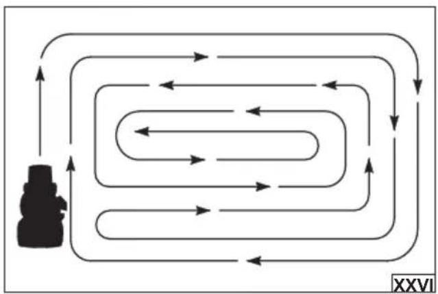
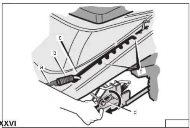
Take regular breaks during work to avoid fatigue and overwork. This will allow better product control and reduce the risk of accidents. When operating the mower with side discharge fitted over large areas, it is recommended to start mowing by moving to the right so that the cut grass is spread away from shrubs, fences, driveways, etc. After one or two rounds, change direction by moving to the left until mowing of the area is completed, as shown in the figure (XXVI).
Always set a safe speed for better control of the machine.
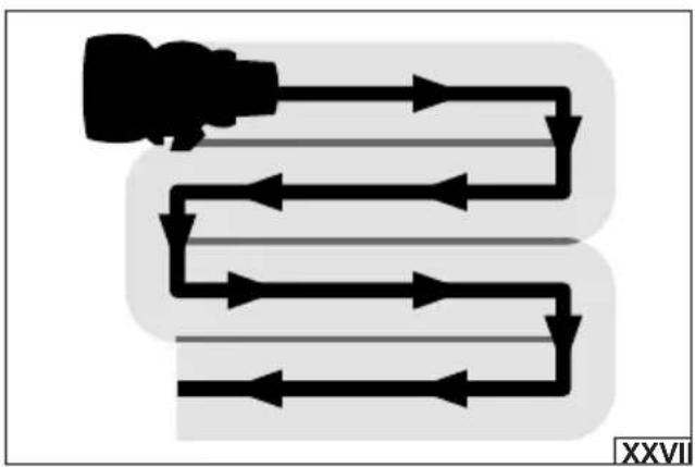
When operating the mower with the grass catcher fitted, move in rows (XXVII). Rows should be kept equal in width, slightly overlapping so as not to leave any space.
Take special care when changing the direction.
When cutting the grass near flower beds, move around the flower beds with the left side of the mower housing.
Empty the catcher regularly during operation.
When work is complete, stop the machine, switch off the blade drive, put it in neutral gear, set the parking brake, then stop the engine and pull out the ignition key. Allow the machine to cool completely, disconnect the spark plug and proceed with maintenance.
ATTENTION! If a foreign object hits the lawnmower during operation, Immediately stop the machine, switch off the blade drive, move the gearshift lever to the neutral position marked "N", set the parking brake, then stop the engine and pull out the ignition key. Allow all components to cool completely, then disconnect the spark plug wire.
Then check the machine for damage. If the damage is detected, it is forbidden to continue working before removing the damage.
Excessive vibration during operation can be caused by the lawnmower damage. In that case, stop working, disconnect the spark plug cable, and check the product.
EN
Recommendations for working on hills
Do not drive up or down slopes that are too steep.
Never drive across a hill.
Move the gearshift levers to the slowest speed position before going downhill or uphill.
Do not stop or change speed on a hill. If you need to stop, immediately press the clutch/brake pedal forward and then set the parking brake.
To continue on an uphill gradient, make sure the gearshift lever is in the slowest speed position. Move the throttle levers to the slow speed position and then release the clutch/brake pedal.
If it is necessary to stop or start on an uphill slope, always allow sufficient space in case of possible rolling of the machine when the clutch/brake pedal is released.
Take special care when changing direction on a slope. When driving on a slope or on an uphill bend, reduce the engine speed by moving the throttle lever to the slow speed position to prevent accidents.
Never exceed the maximum permissible operating angle on slopes.
Refuelling (XXVIII)
ATTENTION! The fuel is highly flammable! All safety precautions regarding the handling of fuel must be observed. Do not fill the fuel tank while the machine is running. Do not refuel near an open flame. Smoking is not permitted in the refuelling area. Do not spill fuel. In the event of a fuel spillage, dry up the spilled fuel thoroughly before starting the scarifier. Tighten the fuel filler cap firmly and securely. Store fuel in tightly closed, approved containers away from heat sources and out of the reach of children.
Stop the engine according to the procedure described under "Stopping the engine".
Allow the engine to cool down.
Use 95-octane unleaded petrol or better. To refuel, unscrew the fuel tank lid (a) and pour fuel into the tank filler hole (b). When filling fuel, it is recommended to use a filler nozzle or funnel to reduce the risk of fuel splashes. Do not fill the fuel tank above the top wall of the fuel tank (c). Leave a headroom of air between the fuel level and the top of the fuel tank. If the fuel is splashed, thoroughly wipe off its residues. Wait until the vapours have completely evaporated and carry out the start-up at a different place than at which the fuel was filled. Once the fuel has been filled, close the filling opening of the fuel tank (b) with the lid (a).
Re-start the engine according to the procedure "Start-up of the combustion engine".
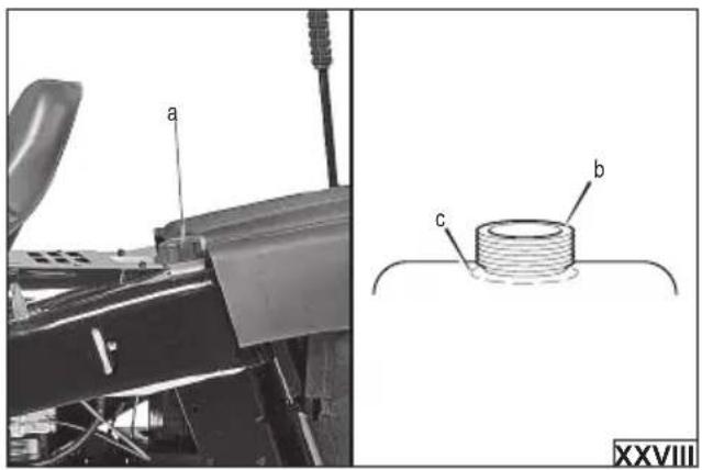
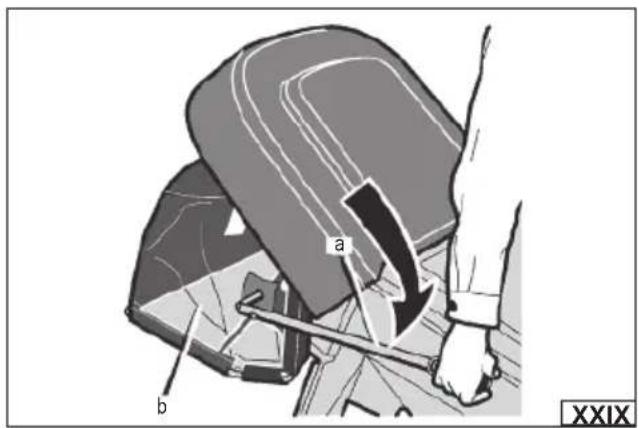
Emptying the grass catcher (XXIX)
Press the clutch/brake pedal fully forward to stop the machine.
Move the blade drive lever to the off - STOP position.
Move the gearshift lever to the neutral position marked "N".
Immobilise the machine with the parking brake. Ensure that the parking brake is applied and that the machine does not change its position when stationary.
Grip the grass catcher emptying lever (a) with the right hand, then move the lever forward until the grass catcher (b) is empty.
MACHINE MAINTENANCE
WARNING! Before servicing and adjusting the mower, stop the machine, switch off the blade drive, move the gear lever to the neutral position marked "N", set the parking brake, then stop the engine and remove the ignition key.
Allow all components to cool completely, then disconnect the spark plug wire.
Use personal protective equipment such as protective gloves, eye protection, and protective clothing during the maintenance.
Cleaning the mower
Before and after each use, check the patency of the vents and clean them if necessary.
If the grass catcher is used during mowing, it must be emptied and cleaned of grass residue and debris after each use. Remove the rear ejection duct and clean the inside.
Remove grass residue and dirt from the cutting blade with a soft cloth. Apply a thin layer of oil to the cleaned blade to prevent corrosion.
Having finished your work, clean the housing, the vents, all switches and guards with compressed air (at 0.3 MPa maximum), a brush or a dry cloth. Do not use any chemicals or cleaners. Clean the steering wheel, levers and handles with a dry clean cloth.
Scheduled inspections
Periodic inspection and maintenance of the following machine assemblies must be carried out.
ATTENTION! All maintenance must be carried out with the machine switched off and not running. After switching off the engine, allow the engine and machine components to cool down completely and then disconnect the spark plug wire.
ATTENTION! If a service operation is not described below, This means that the machine must be serviced by a specialist service centre for this purpose.
ATTENTION! Where solvent is used for cleaning, avoid contact of the solvent with skin and eyes. Use personal protective equip-
EN
ment.
During the warranty period, the user cannot disassemble the machine or replace other assemblies or components than those listed below, as this will result in the loss of warranty rights. Any irregularities found during the inspection or the operation signal the need for repair to be done at the service centre. After each transport and after every 25 hours of operation, check that the tightness of the screw connections is correct.
Maintenance of the combustion engine and electrical system
The mower engine is located under the seat base. For an easier access to the engine components, open the seat base fully by grasping the handle and then secure its position with the posture handle support bar.
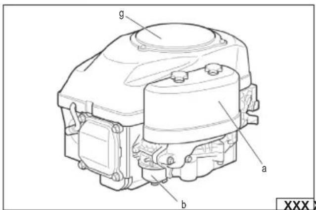
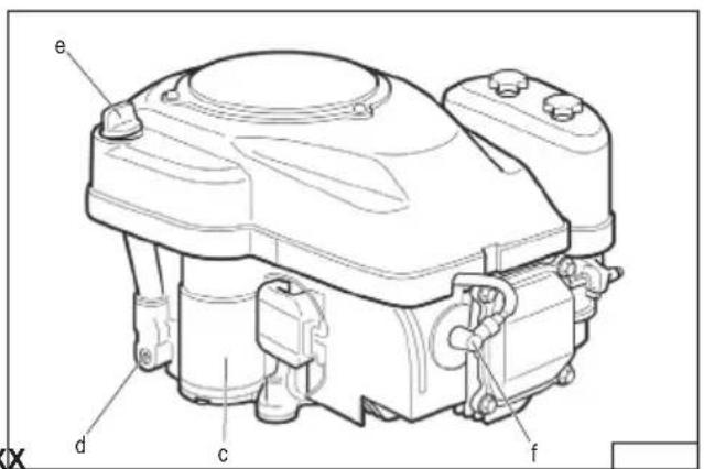
The following engine components are shown in the figure (XXX):
a. air fi lter
b. carburettor
c. starter
d. oil drain plug
e. oil fi ller
f. spark plug cable
g. engine cover
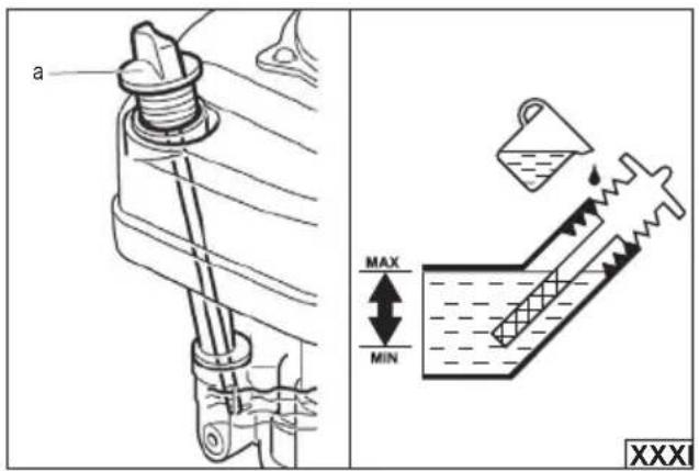
Checking the oil level (XXXI)
Unscrew the oil fi ller (a) and remove the oil level indicator.
Clean and dry the indicator with a clean cloth.
Insert the indicator back into the hole, but do not turn it. Then remove and check the oil level indicated.
If the indicated level is too low, the oil must be topped up to the upper level of the indicator (dashed box).
Screw the indicator into the oil filling hole.
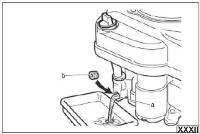
Changing engine oil (XXXII)
The engine oil should be changed after the first 2 to 5 hours of operation. Every subsequent oil change should be carried out every 25 hours of operation.
ATTENTION! It is best to change the engine oil as soon as the engine has come to a standstill. Then the oil is the thinnest and will flow out of the engine gearbox the fastest.
Care must be taken when changing the oil. As soon as the engine stops, the oil is hot and can cause burns. The oil tank has a drain opening (a). Place a container with a capacity greater than that of the oil tank underneath the drain opening. Unscrew the drain valve (b) completely using a wrench. Allow the oil to flow into the tank and then screw in the drain valve using a wrench.
Wipe any oil residue dry.
Top up the oil according to the procedure described under "Preparing for operation".
ATTENTION! Dispose of used engine oil in accordance with the local regulations. It is forbidden to spill engine oil into the sewer system.
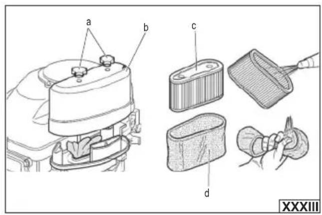
Air fi Iter maintenance (XXXIII) – every 25 hours of operation
ATTENTION! Do not operate the tool without a correctly installed air filter or with a defective air filter. Otherwise the combustion engine may aspirate impurities that would normally settle on the air filter. Impurities can lead to malfunctions or, ultimately, cause its failure.
Fully unscrew the knobs securing the filter housing (a) and then remove the filter cover (b). Remove the filter from the base. The air filter consists of two elements, a paper one and a sponge one. Carefully inspect each filter element for holes, tears and damage. If any filter element is damaged or cannot be cleaned during maintenance, it must be replaced with a new, defect-free one.
Clean the paper element (c) with a jet of compressed air (at a pressure of no more than 0.2 MPa), blowing the dirt from the inside or sucking the dirt from the outside with a narrow hoover brush. Due to the delicate structure of the paper filter, gentle cleaning is recommended. The paper piece should not be soaked in water or any other liquid. Do not brush to avoid rubbing dirt into the filter structure.
Clean the sponge element (d) in warm water with dishwashing liquid, rinse thoroughly and allow to dry completely. Soak the air filter sponge with clean engine oil and squeeze it out so that the filter remains slightly moist only.
Using a cloth slightly dampened with water, clean the inside of the filter base and the filter cover of the filter. Care must be taken to prevent dust and debris from entering the hose leading to the carburettor.
Place the sponge element (d) over the filter paper element (c). Install the filter in place and fix the filter cover. Ensure that the filter cover (b) is tightly closed and that the filter housing fixing knobs (a) are correctly tightened.
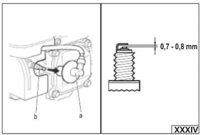
Spark plug maintenance (XXXIV) – every 100 hours of operation
Disconnect the cable (a) from the spark plug (b). Unscrew the spark plug with the spark plug wrench. Use a wire brush to clean carbon deposits off the electrodes (so-called combustion deposits). Check the distance between the electrodes, it should range between 0.7 mm and 0.8 mm.
EN
If burned electrodes or the ceramic casing is broken, replace the spark plug with a new one. It is possible to use spark plug type RC12YC.
Screw in the candle (b). Connect the cable to the spark plug (a).
Draining the fuel system
ATTENTION! The fuel is highly flammable! All safety precautions regarding the handling of fuel must be observed. Ensure that the machine engine is cooled down before draining the fuel system. Drain the fuel system externally. Do not empty the fuel tank near a fire. Do not smoke when emptying the fuel tank.
Fuel in the fuel system of a mower can lose its properties over time or build up deposits that are dangerous to the engine. If the machine will be stored for 30 days or longer, the fuel system should be emptied of fuel beforehand to prevent damage to the fuel system and engine.
Fuel can be extracted from the fuel tank using a special pump designed for this purpose, or the machine's engine can be started and the engine allowed to run until the system runs out of fuel and the engine stops.
Before refilling the tank with fuel, ensure that the fuel used is fresh and free from contamination. Use good quality fuel. Never use engine or carburettor cleaner.
Charging the battery (IV)
ATTENTION! The battery should be charged away from sources of fire. Smoking is not permitted while the battery is charging. Keep the battery away from sparks. The ignition of gases escaping from the battery can lead to the battery exploding.
ATTENTION! When handling the battery, do not allow the battery terminals to be short-circuited. Use insulated tools when fitting/removing the battery.
The mower is equipped with a maintenance-free lead-acid battery that does not require checking the electrolyte level. The battery has been charged at the factory. In the event of prolonged storage, e.g. in winter, it is recommended to charge the battery once every three months to prevent damage from discharge.
If starting the machine is difficult or impossible, the battery should be charged.
If the battery cannot be recharged, replace it with a new one. Always replace the batteries with the original ones, identical to the ones installed in the mower at the factory.
A used battery should not be disposed of with household waste, the battery should be disposed of in accordance with local regulations.
The battery must be removed from the machine before charging. To do this, open the seat base completely by grasping the handle and then secure its position with the posture handle support bar. Unlock the bracket (b) securing the battery from the lower hitch, then pull the bracket from the upper hitch. Disconnect the cable terminal from the battery terminal in the following order:
Unlock the protective cap from the black cable clamp (g). Unscrew the wing nut (f) and remove the screw (e) from the black cable terminal (g), then disconnect the black cable terminal (g) from the battery terminal (h) marked “-”.
Unlock the protective cap from the red cable clamp (c). Unscrew the wing nut (f) and remove the screw (e) from the red cable terminal (c), then disconnect the red cable terminal (c) from the battery terminal (d) marked “+”.
Remove the battery from the base. Charge the battery with a charger (available separately) suitable for the type and parameters of the battery, as recommended in the charger manufacturer's operating instructions.
Mower maintenance
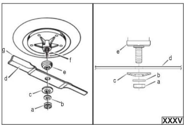
Blade (XXXV) replacement
WARNING! Ensure that the engine and all machine components are cooled down and the spark plug wire is disconnected before proceeding to replace the cutting element. Use personal protective equipment such as protective gloves, eye protection and protective clothing.
Check regularly for wear and tear and the presence of damage to the blade. Replace the blade with a new one if excessive wear, damage or loss of performance is observed. Always replace the blades with the original ones, identical to the ones installed in the mower at the factory. Only the use of original spare parts can maintain product safety. The blade should be replaced by an experienced user. To do this, contact an authorised service centre of the manufacturer. The blade should be replaced every two years or 50 hours.
Removal of the blade is possible from the underside of the mower housing. Drive into a channel suitable for the width of the machine so that free and safe access to the cutting element is possible. Only set up the machine on hard surfaces. Do not tilt the machine. Carefully secure all wheels of the mower at the work site to prevent uncontrolled movement.
Lock the blade so that it does not rotate during removal. Unscrew the retaining nut (a), remove the washer (b), conical washer (c), blade (d) and blade retaining collar (e) from the drive axle (f). Clean the inner part of the mower housing, the drive axle and the attachment adaptor of the mower. On the drive axle (f), place the blade retaining collar (e), the new cutting blade (f) so that its curved edges (g) point upwards, the conical washer (c) so that its flat edge is against the blade, the washer (b), then screw on the retaining nut and tighten using a torque wrench and applying a torque of 47.5 Nm.
EN
Levelling the mower housing
WARNING! Before starting to level the cutting element housing, ensure that the engine and all machine components are cooled down and the spark plug wire is disconnected. Use personal protective equipment such as protective gloves, eye protection and protective clothing.
Level the mower housing if uneven mowing is observed or if there is a drop in performance. Make sure the machine is standing on a firm, flat surface. Ensure that the tyre pressure is correct, as recommended in the “Preparing for operation” section of the manual.
The method of levelling the mower housing is shown in the figures:
(XXXVI) – There is a cover on the mowing height adjustment guide to prevent from moving the height adjustment lever to the levelling position. Open the safety cover (a), then move the height adjustment lever (b) to the levelling position (c).
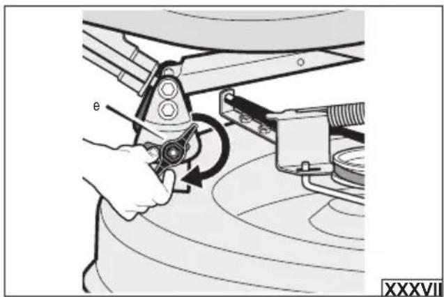
(XXXVI), (XXXVII) – Loosen the rear (d) and front (e) adjustment knobs. Ensure that the bottom edges of the mower housing are parallel to a flat surface, then tighten the front (e) and rear (d) adjustment knobs. Tighten the adjustment knobs using a torque spanner. Tighten the plastic adjustment knobs using 9.5 Nm torque, and tighten the metal adjustment knobs using 13.5 Nm torque. Ensure that all adjustment knobs are correctly tightened and that the mower housing does not change its position during operation.
(XXXVIII) – Move the height adjustment lever (b) to one of the positions (f) in the cutting height adjustment range, then close the safety cover (a).
Check that the grass cutting level is even. In the event of irregularities, repeat the above steps.
ATTENTION! Do not operate if the height adjustment lever is in the levelling position (c). This can lead to damage to the mower housing and blades and serious injury.
Dismantling the wheel
If operations such as tyre replacement are required, the re-fitting of the wheels must be carried out as shown in the figure:
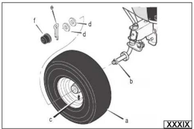
(XXXIX) - Front wheel assembly.
Place the front wheel (a) on the axle (b) so that the valve (c) is on the outside of the machine, then push the wheel backwards.
Fix the wheel with washers (d) and pin (e). Bend outwards the legs of the pin (e). Check that the wheel is properly secured and will not slip out during operation.
Fit the cap (f) to the wheel (a). Ensure that the washer (d) holds the cap (f) in place.
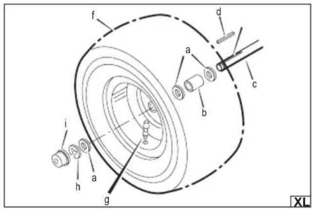
(XL) - Rear wheel assembly.
Place the washers (a) and spacer (b) on the axle (c), in the order shown in the figure (XL). Place the square pin (d) in the axle slot (e), place the rear wheel (f) on the axle (c) so that the valve (g) is on the outside of the machine and then move the wheel backwards. Fix the rear wheel with washer (a) and ring (h). Check that the wheel is properly secured and will not slip out during operation. Fit the cap (i) to the wheel (f). Ensure that the washer (a) holds the cap (i) in place.
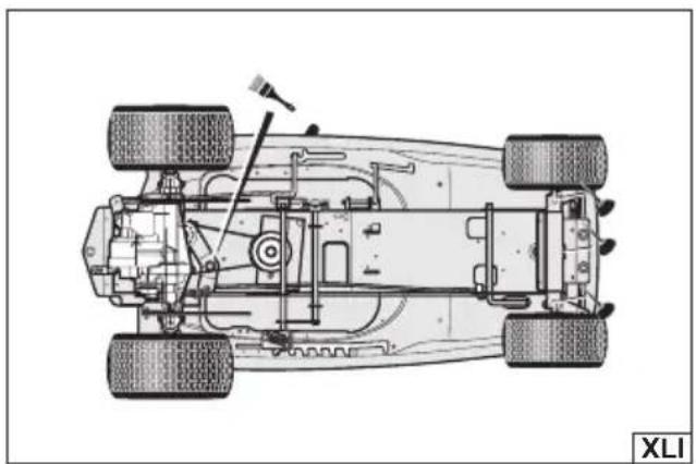
Lubrication
Before storage, it is recommended to lubricate the areas indicated in the figure (XLI). Lubricate the indicated areas with engine oil.
If the machine is used in dry and sandy areas, it is recommended to use dry graphite grease for lubrication.
Lubricate steering gear assembly components with a precision oiler, lubricate other areas with a brush.
Troubleshooting
Typical faults and possible solutions are outlined below. If in any doubt, stop using the product and contact the manufacturer's authorised service centre.
The engine does not start:
-
Check the oil level.
-
Check fuel level.
-
Replace spark plug.
-
Clean the cable and battery terminals.
-
Start the engine as described under "Starting the internal combustion engine" in the instructions.
Engine starting difficulties:
-
Replace spark plug.
-
Charge the battery.
-
Clean the cable and battery terminals.
The engine does not run evenly or there is a problem with loss of power:
-
Check the oil level.
-
Clean the air filters
EN
- Replace spark plug.
Engine overload – use a lower gear.
Engine does not run smoothly at higher revs
-
Clean the air filters
-
Replace spark plug.
-
Change the position of the throttle lever.
The engine stops when the blade drive is engaged
-
To activate the seat sensor, always sit in the middle of the seat.
-
Check the wiring harness for damage or loose connections. Repair the damaged cable.
Engine stops on a slope
-
Mow up and down the slopes. Never mow across a slope.
-
To activate the seat sensor, always sit in the middle of the seat.
Hot engine causes power loss
-
Clean the air filters
-
Check the oil level.
Excessive vibrations
-
Replace the blade
-
Check tyre pressure.
-
Check that the engine screws are not loose.
Grass is not properly disposed of
-
Stop the engine. Disconnect the spark plug wire. Clean the mower housing.
-
Increase cutting height.
-
Replace the blade
-
Reduce drive speed.
-
Increase engine speed
Uneven mowing
-
Check tyre pressures.
-
Adjust the level of the mower housing
-
Check the front axle. If the front axle does not rotate freely, loosen the axle bolt.
Rear wheels slip on uneven ground
- Check the front axle. If the front axle does not rotate freely, loosen the axle bolt.
Storage
Ensure that the spark plug wire is disconnected.
Lubricate the machine components indicated under "Lubrication" in the instructions.
Always empty the fuel system before storage as described in the section of the manual "Emptying the fuel system".
Remove the battery and then charge it as described under “Charging the battery” in the instructions. Thoroughly clean the cable terminals and the battery terminals. Corrosion of the terminals can adversely affect the performance of the battery and lead to improper operation of the machine. Store the battery in a cool, dry place.
Clean the internal and external parts of the mower and preserve with an anti-rust agent.
Store the mower in a dry, well-ventilated and covered room. The place of storage should protect the tool from access by children.
The product should be stored at a temperature between 10^ C and 30^ C. It is recommended that the product is stored in its original packaging or another packaging that protects it from dust.
Store the mower in a horizontal position.
Transportation
Note! Always empty the fuel tank prior to transport as described in the section of the manual “Emptying the fuel system”. The product must be secured against movement before transport. Protect the product from impacts and strong vibrations during transport. The mower must be transported in a horizontal position. After each transport, check that the tightness of the screw connections is correct.
PRODUKTBESCHREIBUNG
CARACTÉRISTIQUES DU PRODUIT
Vibrations excessives
DODATNE SIGURNOSNE UPUTE
Preporučeno gorivo, bezolovni benzin E10, s oktanskim brojem od najmanje 95.
atmospheric-trayable government's office of the United States (XVI).
DEKLARACJA ZGODNOŚCI | DECLARATION OF CONFORMITY DECLARATIE DE CONFORMITATE
0824/YT-85550/EC/2024
We declare and guarantee with full responsibility that the following products:
meet requirements of the following European Standards / Technical Specifications:
and fulfill requirements of the following European Directives:
Machinery and safety elements
Emissions from non-road mobile machinery
Serial number: concern all serials numbers of item(s) mentioned in this declaration
Manufacturer quality-control system, examination of the manufacturer's technical file and periodical inspection by notified body
Measured sound power level on an equipment representative for this type:
Guaranteed sound power level for this equipment:
The person authorized to compile the technical file: