Haaga 677 Plus - Sweeper Starmix - Free user manual and instructions
Find the device manual for free Haaga 677 Plus Starmix in PDF.

User questions about Haaga 677 Plus Starmix
0 question about this device. Answer the ones you know or ask your own.
Ask a new question about this device
Download the instructions for your Sweeper in PDF format for free! Find your manual Haaga 677 Plus - Starmix and take your electronic device back in hand. On this page are published all the documents necessary for the use of your device. Haaga 677 Plus by Starmix.
USER MANUAL Haaga 677 Plus Starmix
natural_image
Line drawing of a manual lawn mower with two blades and handle (no text or symbols)
Sprachverzeichnis
haaga 677 plus
part of starmix

haaga
text_image
Technical diagram of a lawn mower with numbered parts for identificationDE
text_image
Technical diagram of a mechanical assembly with numbered components labeled 14 through 17natural_image
Technical line drawing of a mechanical component with internal channels and a numbered label (18), no readable text or symbols present.text_image
Anatomical diagram of a biological structure with numbered labels pointing to specific parts.text_image
Technical diagram of a car interior with numbered components and labeled partstext_image
Technical diagram showing mechanical assembly with numbered components and a magnified inset highlighting parts 26 and 27.text_image
Technical diagram of a vacuum cleaner with labeled parts 1 and 2, showing mechanical components and hand interaction.text_image
(1) (B) (10) (B)text_image
(I) (II) (A)text_image
Diagram of a car interior showing directional arrows and labeled parts, likely illustrating motion or flow in vehicle dynamics.text_image
Technical diagram showing mechanical assembly steps labeled A and B, with numbered components 3, 4, and 5 indicating different parts of a device.text_image
Technical diagram of a car electrical switch with numbered components labeled 1 to 4natural_image
Technical diagram of a car interior showing steering wheel, dashboard, and gear shift (no text or labels)natural_image
Line drawing of a car interior showing dashboard, seatbelt, and steering wheel (no text or symbols)text_image
Technical diagram showing a mechanical component with labeled parts, including a top view and side views.text_image
Technical diagram of a boat's internal components with numbered labels pointing to different parts.text_image
Technical diagram of a mechanical device with numbered components and directional arrows indicating motion or flow.text_image
Technical diagram showing car engine compartment with labeled parts and a zoomed-in view of the internal component.text_image
Technical diagram of a vehicle engine assembly with numbered components and an inset view showing internal components.text_image
Technical diagram showing mechanical assembly with numbered components and labeled partstext_image
Technical diagram showing a mechanical assembly with labeled parts 1 and 2, likely illustrating a turning or machining process.text_image
Diagram of a robotic car interior with labeled parts and motion arrows indicating movement or flow.text_image
Technical diagram showing mechanical assembly steps with labeled components A and B, including numbered parts 3, 4, and 5.natural_image
Technical line drawing of a mechanical device with no visible text or symbolschemical
Chemical structure of a Pb-based waste bin and its corresponding recycling symbol1.2 Conventions....37
1.3 Symbols and markings 37
1.4 Limitation of liability 37
1.5 Warranty 37
1.6 Copyright protection....38
1.7 Target group....38
- Security 38
2.1 Intended use 38
2.2 Improper use....38
2.3 Responsibility of the user 38
2.4 General safety instructions....39
2.5 General safety instructions for the battery, charging socket and charger.... 39
2.6 Hazard warnings on the device....41
2.7 Personal protective equipment....41
-
Technical data....42
-
Assembly and function.... 43
-
Transportation/transportation......45
5.1 Delivery 45
5.2 Scope of delivery....45
5.3 Handling packaging materials 45
5.4 Storing the sweeper 45
5.5 Carrying the appliance....46
5.6 Transporting the appliance in the vehicle....46
- Commissioning 47
6.1 Fitting the push bar and handle fittings....47
6.2 Fitting the push handle to the device....47
6.3 Connect the battery connection cable 48
6.4 Charge the battery....49
- Operation 50
7.1 Before starting work 50
7.2 Height adjustment of the disc brushes 51
7.3 Set the hold-down device 51
7.4 Battery operation and LED display....52
7.5 Overload protection 53
7.6 Manual operation....54
7.7 Emptying the debris container....54
- Troubleshooting 55
8.1 Fault table part 1....56
8.2 Fault table part 2....57
8.3 Troubleshooting Procedure 58
8.4 Remove and check fuse F1 58
- Maintenance and cleaning....60
9.1 Maintenance schedule....61
9.2 Remove blockage....61
haaga 677 plus
EN
9.3 Align bristles....62
9.4 Clean the appliance....62
10. Decommissioning/storage/storage 62
10.1 Dismantle the push handle....62
10.2 Disconnect the battery connection cable 63
10.3 Storage/storage 64
10.4 Disposal 64
11. REACH....65
12. EC Declaration of Conformity 65
1. General
These operating instructions are part of the haaga 677 plus sweeper (year of manufacture: from 2025) and apply exclusively to this appliance.
The operating instructions provide important information for the safe and efficient use of the appliance.
The prerequisite for working safely with the appliance is compliance with all the specified safety information and instructions.
- Read the operating instructions carefully before using the appliance.

CAUTION
Read the instructions before using the machine!
- Keep the operating instructions in a safe and accessible place for the entire service life of the appliance.
• Pass the operating instructions on to any subsequent owner or user of the appliance.
1.1 Address
Electrostar GmbH
Hans-Zinser-Str. 1-3
73061 Ebersbach/Fils
Germany
Phone: +49 (0)7163 9988-100
Fax: +49 (0)7163 9988-155
info@starmix.de
www.starmix.de
1.2 Conventions
In order to be able to work optimally with the operating instructions, the following explanations on typographical conventions must be observed.
Enumeration
- Texts displayed in this way are bullet points.
Work sequence
- Step 1 of the work sequence
- Step 2 of the work sequence
- Step 3 of the work sequence
The sequence of work steps must be observed.
Tip
» Tips and instructions (not machine damage) are shown as follows.
1.3 Symbols and markings
Always comply with all warnings and safety instructions! Always act with caution when working to avoid accidents, personal injury and damage to property!
Structure of the safety instructions

SIGNAL WORD
Type and source of danger
Possible consequences
• Measure to avoid the danger
Danger level
| Danger level Probability of occurrence | Consequences of non-compliance | |
 | DANGER | Immediately Death, serious injury |
 | WARNING | Possible Death, serious injury |
 | CAUTION | Possible Minor bodily injury |
| NOTE Possible Material damage | ||
DANGER
WARNING
CAUTION
1.4 Limitation of liability
Electrostar GmbH accepts no liability for damage and consequential damage caused by the points listed below:
• Non-compliance with the operating instructions
- Use of unauthorized spare parts / incorrect spare parts / spare parts that do not comply with the manufacturer's specifications
- Unauthorized modifications, attachments and conversions to the appliance
1.5 Warranty
The regulations described in the General Terms and Conditions of Electrostar GmbH apply.
1.6 Copyright protection
The operating instructions are protected by copyright for Electrostar GmbH.
The operating instructions contain instructions and drawings or drawing extracts of a technical nature which may not be reproduced, distributed or used for competitive purposes without authorization or communicated to others, either in whole or in part.
Electrostar GmbH reserves the right to obtain permission to use copies or information from these operating instructions for publications or to pass them on to third parties.
Infringements will result in a claim for damages by the manufacturer. Further claims remain reserved.
1.7 Target group
These operating instructions are intended for the user of this sweeper.
2. Security
Observe the following instructions to avoid malfunctions, damage and health hazards!
2.1 Intendeduse
The haaga 677 plus sweeper is intended exclusively for removing road dirt such as leaves, grass, grit, sand and similar debris from fl at and hard surfaces.
The appliance is suitable for commercial use, e.g. in hotels, schools, hospitals, factories and offices.
2.2 Improperuse
Any use other than that described in the section „Intended use“ is considered improper use. The user of the appliance is solely liable for any resulting damage.
The sweeper must not be used for sweeping hazardous, fl ammable or glowing materials (cigarettes and matches), liquids, explosive or hazardous dusts (Ex), acids or solvents.
The sweeper must also not be used to sweep water, concrete, mortar, cement or dust containing gypsum.
Wet sweeping material such as snow, manure, cow dung and muddy substances such as faeces must also not be swept with the sweeper.
The sweeper must not be used in potentially explosive areas or as a means of transportation.

WARNING
Do not use on slopes
2.3 Responsibility of the user
A user is any natural or legal person who uses the sweeper or allows third parties to use it and is responsible for the safety of the user or third parties during use.
- Supervise children who are in the working area to ensure that they do not play with it.
-
This machine is not intended for use by persons (including children) with reduced physical, sensory or mental capabilities, or lack of experience and knowledge.
-
Persons whose ability to react is impaired, e.g. by drugs, alcohol or medication, must not work with the appliance.
- Persons who are unable to exert themselves due to their state of health must not work with the sweeper.
- Replace any signs on the sweeper that have become illegible.
2.4 General safety instructions
- Make packaging material inaccessible to children. There is a risk of suffocation!
- Do not wear long loose hair, ties, loose clothing or jewelry, including rings.
- When handling the sweeper, be aware that there is a risk of injury from items of clothing and body parts getting caught and pulled in.
2.5 General safety instructions for the battery, charging socket and charger

DANGER
Danger to life due to electric shock!
If the charger is handled incorrectly, there is a risk of fatal electric shock.
- Never use a defective or damaged charger
- Never open or dismantle the charger.
- Check the connecting cable of the charger regularly for damage. If the connecting cable is damaged, pull out the mains plug immediately

DANGER
Danger to life due to explosion!
The charger and sweeper can generate sparks that can ignite dust or vapors. For example, sparks can be generated when the on/off switch is pressed
- Never operate the charger and sweeper in a potentially explosive environment, i.e. in an environment containing fl ammable liquids (vapors), gases or dusts (EX).

WARNING
Risk of injury or accident when handling the battery!
Incorrect handling of the battery can lead to various hazardous situations. The following points must be observed
- Protect the battery from direct sunlight, heat, naked flames and electric sparks
- Do not smoke in the immediate vicinity of the battery.
- Never expose the battery to microwaves or high pressure.
- Do not charge the battery at temperatures below 0°C.
- Never throw it into a fire
- Never charge or use a defective, damaged or deformed battery.
- Never open, damage or drop the battery
- Keep the battery out of the reach of children

WARNING
Risk of injury or accident due to liquid leaking from the battery
Leaking battery fluid can cause skin irritation burns and chemical burns.
- In the event of accidental contact, wash the affected parts of the body with plenty of soap and water
- If the liquid gets into the eyes, do not rub and flush the eyes with plenty of water for a least 15 minutes. Seek additional medical attention.
- Ensure safe handling of the battery
WARNING
Risk of injury or accident due to a short circuit
A short circuit caused by water/moisture can lead to an electric shock and/or fire
- Do not clean the sweeper with a high-pressure cleaner or water jets.
- Avoid driving through puddles.
WARNING
Risk of injury due to external damage to the battery
Leakage of hazardous substances may cause skin irritation and/or burns.
- Wear personal protective equipment (PPE).

WARNING
Risk of injury or accident when handling the charger!
Incorrect handling of the charger can lead to various hazardous situations. The following points must be observed:
- Only connect the charger to a properly installed socket.
- Disconnect the mains plug from the socket after using the charger.
- Fire hazard! Do not operate on a highly fl ammable surface (e.g. paper, textiles) or in a highly fl ammable environment
- If smoke or fire develops in the charger, pu out the mains plug immediately
- Do not cover the charger so that it can cool down unhindered.
- Lay and mark connecting cables in such a way that they cannot be damaged and no one can be endangered - avoid the risk of tripping!
NOTE
Incorrect handling and improper use of the battery, charger and charging socket can result in damage to property or equipment. The following points must be observed
- Only use the battery with the sweeper and the manufacturer's charger.
NOTE
- Only for charging a geometrically suitable battery in accordance with the values in chapter „3. Technical data“ use
- Only connect the charger to the mains voltage and mains frequency specified or the rating plate.
- Do not pull the mains plug out of the socket by pulling on the connecting cable; always pull on the mains plug.
- Have a damaged connecting cable repaired by a qualified electrician
- Only use and store the charger in closed and dry rooms. Protect the charger from rain and moisture.
- Only store the charger and battery in the specified temperature ranges in accordance with the values in chapter „3. Technical data" use.
- Never connect the contacts of the charger to metallic objects (e.g. nails, coins, jewelry) (short-circuiting)short-circuit). The charger can be damaged by a short circuits can be damaged by a short circuit.
- Never connect (short-circuit) the battery terminals or the contacts of the charging socket with metal objects (e.g. nails, coins, jewelry). The battery or the sweeper's electronics can be damaged by a short circuit.
- Do not use metal transport containers for the battery.
- Protect the battery from rain and moisture.
- To prevent deep discharge of the battery, the blue battery connection cable must be disconnected if the battery is stored for more than approx. 2 months without recharging. For information on storage and storage and disconnecting the battery, please refer to chapter „10.3 Storage/storage“ and chapter "10.2 Disconnecting the battery connection cable" in these operating instructions.
- For storage periods of approx. 6 months or more, the battery must also be fully charged beforehand to maintain battery performance. Information on charging the battery can be found in chapter „6.4 Charge the battery“ of these operating instructions.
2.6 Hazard warnings on the device
The following pictograms are attached to the sweeper or the type plate:

CAUTION
When working, ensure that you observe the safety instructions described in the operating instructions.

Instruction manual
Read the operating instructions carefully before using the appliance.
Danger of being pulled in and trapped
When working on the appliance during operation, troubleshooting, maintenance and cleaning, there is a risk of entrapment and injury from rotating parts. Observe the safety instructions described in the operating instructions.

Charger and battery
Only use the charger supplied with the sweeper and approved by the manufacturer to charge the battery.
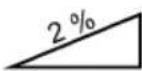
Maximum gradient
The maximum incline of a sweeper refers to the maximum angle of inclination that the device can safely overcome in order to perform its cleaning function effectively without tipping or sliding.
2.7 Personal protective equipment
Personal protective equipment must be worn when working in order to minimize health hazards. Therefore:
- Before starting any work, put on the designated protective equipment properly and wear it during work.
EN

Sturdy footwear
Wear sturdy shoes with non-slip soles.

Sturdy protective gloves
Wear sturdy protective gloves.

Dust mask
Wear a dust mask.
3. Technical data
Basic data haaga 677 plus
| Technical data 677 plus | |
| Sweeping width in millimeters [mm] 770 | |
| Sweeping performance in square meters per hour [ m^2/h ] 3200 | |
| Sweepings container capacity in liters [l] 40 | |
| Weight in kilograms [kg] empty / max (GVW) 21 / 30 | |
| Operating time at full battery power* approx. min 90 | |
| Max. Max. operating temperature from -10 | °C to 40 °C |
| Charging from 0 | °C to 25 °C |
| Storage from -10 | °C to 40 °C |
| Noise and vibration information(measured according to EN 60335-2-72) | 677 plus |
| Sound pressure level _Lp (EN 60335-2-72)* 68 dB (A) | |
| Sound power level _Lw (EN 60335-2-72)* 80 dB (A) | |
| Uncertainty for the specified sound levels (2006/42/EC) 2,5 dB (A) |
*Determined in the operating condition of nominal maximum speed at an ambient temperature of 20 °C / depending on the floor covering.
Vibration information (measured according to EN 60335-2-72) 677 plus
| Handle left, a_h | < 2.5 m/s ^2 |
| Handle right, a_h | |
| Uncertainty (K) (Directive 2006/42/EC) 2.0 m/s ^2 |
| Lead battery | 677 plus |
| Voltage [V] | 12 |
| Capacity [Ah] | 14 |
| Weight in kilograms [kg] | 4,0 |
| Charger | 677 plus |
| Input voltage | 100-240 VAC/50-60 Hz |
| Output voltage [V] | 12 |
| Charging end voltage [V] | 14,5 |
| Charging current [mA] | 3.000 |
| Weight in grams [g] | 300 |
4. Assembly and function
text_image
Technical diagram of a lawn mower with numbered parts for identificationEN
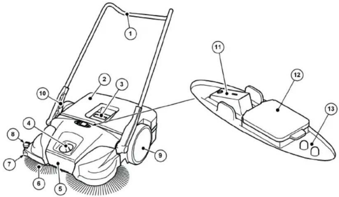
Abb. 1: Component overview 1
| Item no. | Component |
| 1 Push handle | |
| 2 Sweepings container | |
| 3 Container handle | |
| 4 Disc brush height adjustment | |
| 5 Carrying handle | |
| 6 Disc brush | |
| 7 Lateral guide roller | |
| 8 Hold-down device | |
| 9 Impeller | |
| 10 Handle fitting | |
| 11 On/off switch | |
| 12 Charging socket | |
| 13 LED display | |
The appliance is switched to battery operation by pressing the on/off switch (11) and moved forwards by pushing it over the push handle (1). The two disc brushes (6) use the sweeping lip (16) to move the debris towards the debris container (2).
The fine dirt sweeping roller (14) transports the remaining debris into the debris container (2). Power is supplied by a battery (22) installed in the appliance, which must be sufficiently charged for optimum operation of the appliance.
» Information on charging the battery can be found in chapter „6.4 Charge the battery“ of these operating instructions.
During battery operation, the current operating status of the sweeper is shown on the LED display (13).
» Information on battery operation and the LED display can be found in chapter „7.4 Battery operation and LED display“ of these operating instructions.
In addition, the device can also be used temporarily without electrical operation when the battery charge level is low.
» Information on manual operation can be found in chapter „7.6 Manual operation“ of these operating instructions.
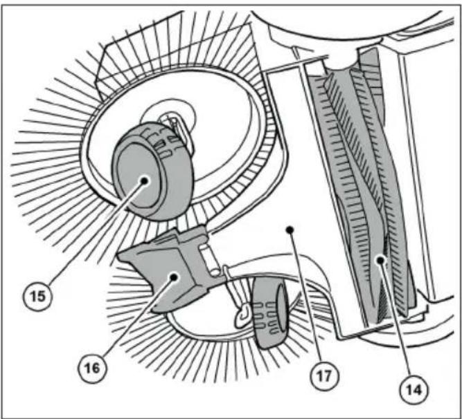
text_image
Technical diagram of a mechanical assembly with numbered components labeled 14 to 17Abb. 2: Component overview 2
Item no. Component
14 Fine dirt sweeping roller
15 Inclined degree
16 Sweeping lip
17 Sweeping plate
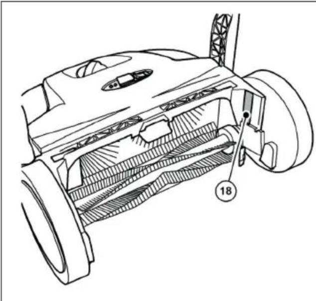
natural_image
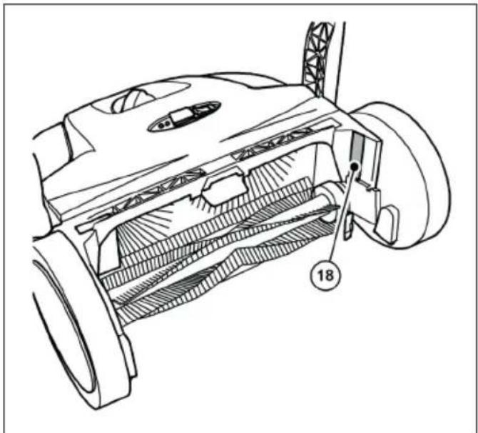
Technical line drawing of a mechanical component with labeled parts (no readable text or symbols)Abb. 3: Component overview 3
Item no. Component
18 Type plate

text_image
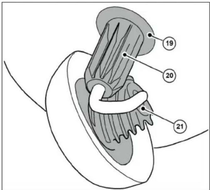
Anatomical diagram of a biological structure with numbered labels pointing to specific parts.Abb. 4: Component overview 4
Item no. Component
19 Coupling housing
20 Tooth sleeve
21 Helical gearing
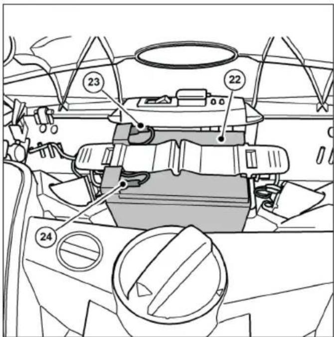
text_image
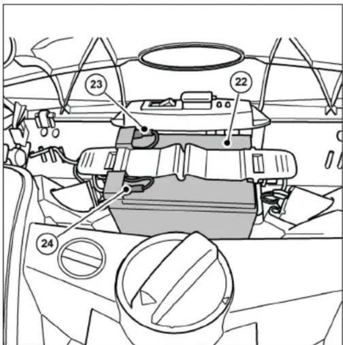
Technical diagram of a car interior with numbered components and labeled partsAbb. 5: Component overview 5
Item no. Component
22 Battery
23 Battery connection cable (red +)
24 Battery connection cable (blue -)
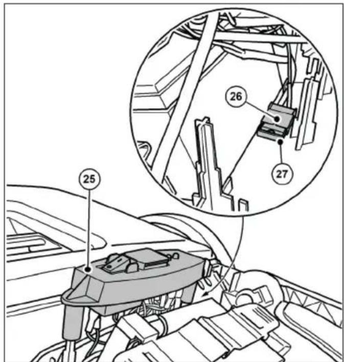
text_image
Technical diagram showing mechanical assembly with numbered components and a magnified inset highlighting parts 26 and 27.Abb. 6: Component overview 6
| Item no. | Component |
| 25 | Switch plate |
| 26 | Fuse holder |
| 27 | Fuse F1 |
» The picture shows the components with the cover open or removed.
5. Transportation/transportation
5.1 Delivery
NOTE
Please have the driver of the parcel service conti rm any visible damage to the oute packaging immediately upon delivery. If trans- port damage is only noticed during unpacking, the parcel service must be notiti ed in writing within 24 hours of delivery in order to hold them liable for the damage.
NOTE
The battery is protected with a transportation lock. There is a cardboard box around the battery. The transport protection (cardboard box) must be removed before commissioning.
5.2 Scope of delivery
• Appliance with battery
- Push handle
- Two handle fittings
- Charger with mains plug
- Instruction manual
5.3 Handling packaging materials
• Always dispose of the packaging material in an environmentally friendly manner.
- Observe the local, regionally applicable legal regulations.
5.4 Storing the sweeper
NOTE
Improper storage, e.g. storage of the device in a damp environment, a connected battery connection cable or an insufficiently charge battery can lead to damage to the sweeper. For information on storing and storing the device, see chapter „10. Decommissioning/storage/storage“.
» The push handle can be removed from the device for space-saving storage. Information on removing the push handle can be found in chapter „10.1 Dismantle the push handle“ of these operating instructions.
5.5 Carrying the appliance

CAUTION
Risk of injury due to the push bar tipping over!
If the push bar tips over, this can cause minor injuries such as crushed fingers or bruising to the user or other persons.
- When carrying the device, hold it in such a way that the push bar cannot tip over.
text_image
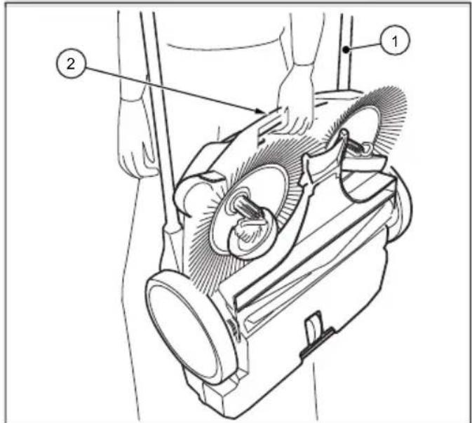
Technical diagram of a vacuum cleaner with labeled parts 1 and 2, showing mechanical components and hand interaction.Abb. 7: Carrying the appliance
- Swivel the push handle (1) fl at forwards.
- Grip the device by the carrying handle (2).
- Carry the appliance so that the disc brushes are pointing away from your body.
5.6 Transporting the appliance in the vehicle

CAUTION
Risk of injury due to improper transportation of the sweeper!
A device that is spun around, slips or tips over can cause injury to the driver or other persons.
- Secure the device with a lashing strap to prevent it from slipping and being thrown around.
- Place the device in a suitable position in the vehicle.
- Secure the device with a tensioning strap.
» For space-saving transportation in vehicles, the push handle can be removed from the appliance. Information on removing the push handle can be found in chapter „10.1 Dismantle the push handle“ of these operating instructions.
NOTE
- Improper transportation can lead to damage to the sweeper.
• To protect the batteries, do not leave the sweeper in a heated vehicle. - Ensure that the device is not accidentally switched on during transportation. If necessary, disconnect the blue battery connection cable from the battery. Information on disconnecting the battery can be found in chapter "10.2 Disconnecting the battery connection cable" of these operating instructions.
6. Commissioning
6.1 Fitting the push bar and handle fi ttings
text_image
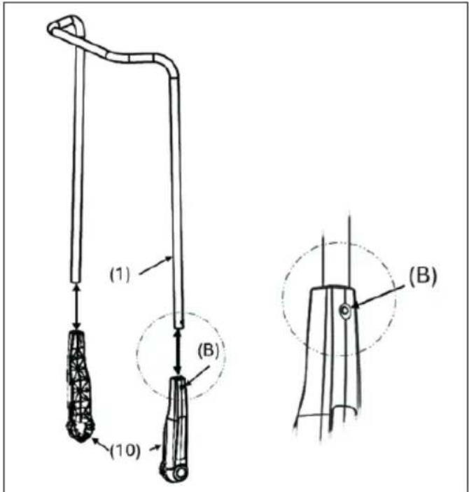
(1) (B) (10) (B)Abb. 8: Fitting the handle fi ttings
On delivery, two handle fittings (10) and the push bar (1) are supplied as individual parts.
- Press the catch spring (B) on the side of the push bar (1) inwards.
- Push the handle fi tting (10) onto the push bar until it engages.
» Make sure that the hole on the side of the handle fi tting is aligned with the locking spring in the push bar. - Proceed in the same way with the second side of the push bar
6.2 Fitting the push handle to the device

CAUTION
Risk of injury due to the push bar tipping over!
If the push bar tips over, this can cause minor injuries such as crushed fingers or bruising to the user or other persons.
- When carrying the device, hold it in such a way that the push bar cannot tip over.
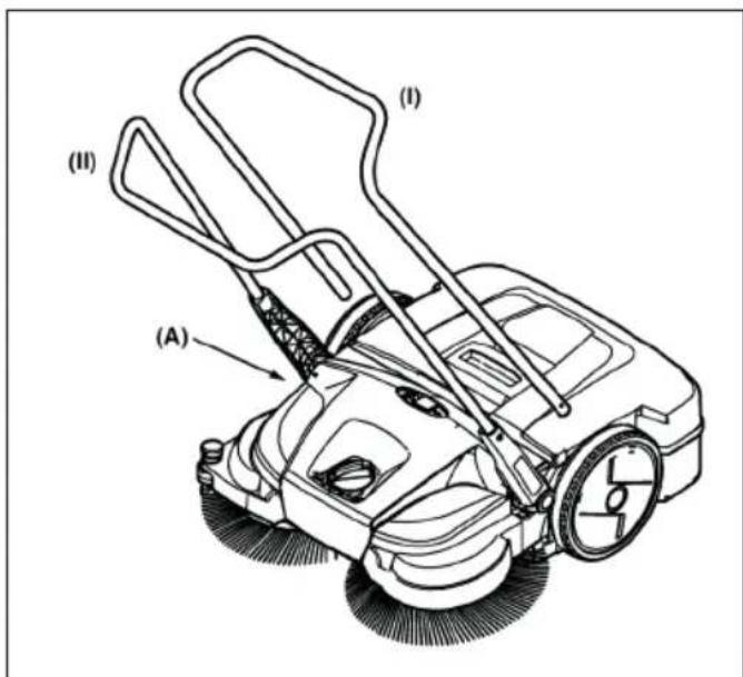
The push bar can be adjusted to the user's height in two stages ((I) and (II)).
» (I): Low level
» (II): Higher level (preferred position)
text_image
(I) (II) (A)Abb. 9: Mounting the push bar
- Position yourself between the push bar in front of the device.
- Place one of the two handle fi ttings with the latching lug on the handle fi tting (10) in the groove provided on the frame (A) so that it can snap into place (Fig. 10).
text_image
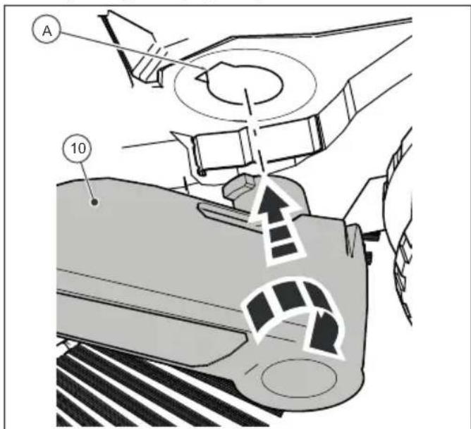
A 10Abb. 10: Fitting the handle fi ttings
- Place the handle fi tting (10) on the other side in the same position.
- The handle fittings can now be snapped into the slots in the appliance (A) with a little pressure and the push handle can be moved into the required position for pushing the appliance.
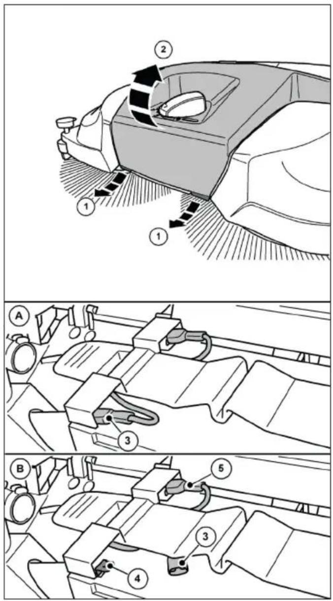
6.3 Connect the battery connection cable
text_image
Diagram of a car interior showing directional arrows and labeled parts, likely illustrating motion or movement in vehicle dynamics.Abb. 11: Opening the hood

CAUTION
Risk of injury due to accidental start-up of the sweeper!
When connecting the battery connection cable, there is a risk of being pulled in if the sweeper is accidentally switched on.
- Before connecting the battery, make sure that the on/off switch on the device is in the "0" position.
» To prevent the battery from self-discharging, the blue battery connection cable is disconnected from the plug-in tab of the battery on delivery and during storage periods longer than approx. 2 months.
1. Pull the tabs (1) on the front bottom edge of the cover (2) slightly forwards.
2. Swivel the cover (2) upwards.
text_image
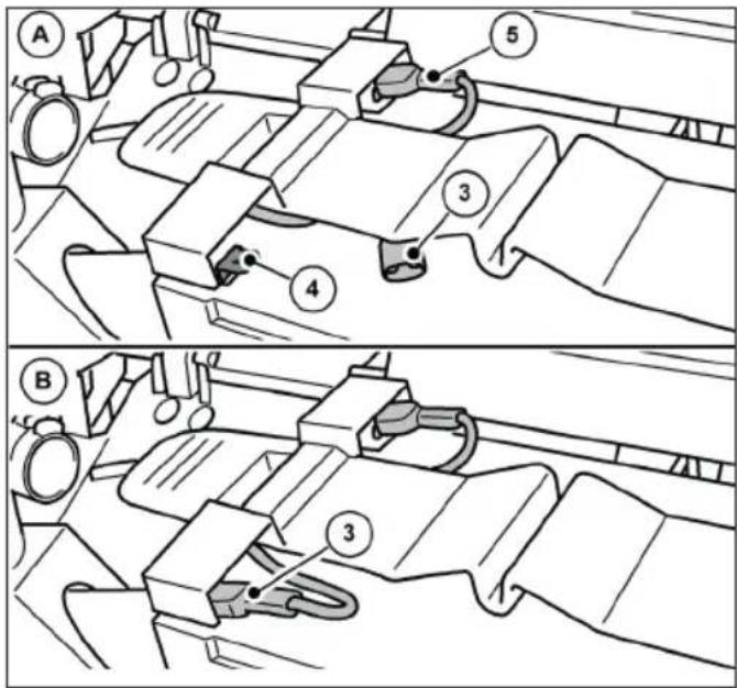
Technical diagram showing two mechanical assembly steps labeled A and B, with numbered components and directional arrows indicating movement.Abb. 12: Connect the battery connection cable
- Plug the blue battery connection cable (3) fully onto the plug-in tab (4) of the battery.
» (A): Battery connection cable not connected.
» (B): Battery connection cable connected.
» The red battery connection cable (5) is connected on delivery.
NOTE
Also ensure that the red battery connection cable (5) is fully and correctly connected. If the battery connection cable is not connected correctly, this can damage the appliance and invalidate any warranty claims
- Close the cover (2) and lock it using the tabs (1).
6.4 Charge the battery
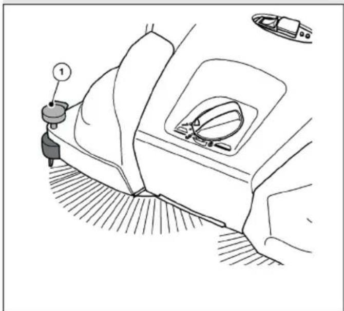
text_image
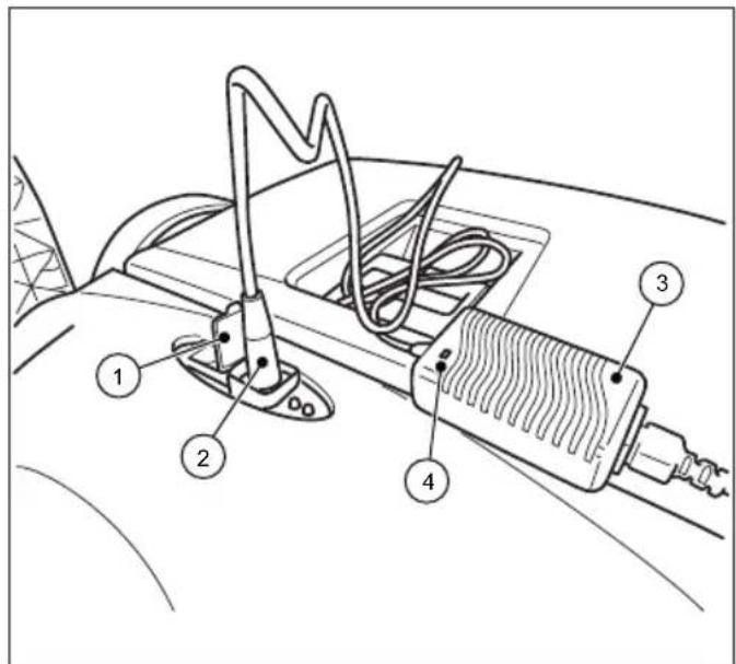
Technical diagram of a car's electrical switch assembly with numbered componentsAbb. 13: Connecting the charger
» It is recommended that the battery is fully charged before first use.
» The charger (3) has a fully electronic voltage and current limiter. This ensures that a connected battery is always kept at the optimum charge level. This prevents the battery from being overcharged.
» To charge the battery, the battery connection cables must be connected correctly. Information on connecting the battery can be found in chapter "6.3 Connecting the battery connection cable" in these operating instructions.
NOTE
- The sweeper must not be switched on during the charging process. This may cause damage to the electrical components of the sweeper
-
Before charging, check the plug of the charger and the connection socket on the sweeper for foreign objects, e.g. electrically conductive objects. Device damage due to short circuit and cable fire
-
Open the protective cap (1) of the charging socket on the sweeper.
- Insert the plug (2) of the charger (3) into the charging socket of the sweeper.
- Connect the mains cable of the charger (3) to a 100-240 V supply connection.
» During the charging process, the LED indicator (4) on the charger lights up "orange". When the battery is fully charged, the LED indicator (4) on the charger changes to "green".
» The charging time essentially depends on the SOC value (state of charge) of the battery before the charging process begins. If the battery is not charged for a longer period of time, the state of charge drops, which increases the charging time. A full charge can take up to approx. 7 hours. Please refer to the information on the outer packaging or on the sticker affi xed to the sweeper before delivery.
NOTE
To achieve an optimum service life and minimize the ageing process, charge the battery at least every 2 months for approx. 10 hours. A fully charged battery reduces the risk of deep discharge and irreparable damage to the battery cells. The battery can also be recharged after short operating times of approx. 15 minutes
7. Operation

DANGER
Danger to life due to unsupervised operation of the sweeper!
Independent (starting) driving due to the rotational movement of the disc brushes and fi ne dirt sweeping roller or on sloping roads can result in serious or even fatal injuries due to collisions in public spaces (road users).
- Do not operate the sweeper unattended
- Switch off the sweeper immediately after parking and store it safely.

WARNING
Risk of cuts from broken glass, metal or other sharp-edged materials!
When emptying the sweeping material container, cuts can be caused by shards of glass, metal or other sharp-edged materials
- Wear the prescribed personal protective equipment!

CAUTION
Health hazard due to dust generated during sweeping!
Inhaling dust can endanger your health.
- Wear the prescribed personal protective equipment!

CAUTION
Risk of injury from hot components!
Working on the hot motor of the sweeper can result in skin injuries.
- Wear the prescribed personal protective equipment!
- Ensure that the motor is hot after the sweeper has been switched off
7.1 Before starting work
- Check the functionality of the device before starting work.
- Check that the push handle is firmly seated in the handle fittings.
- Check that the hopper is firmly seated and in good condition.
- Check the disc brushes and the fi ne dirt sweeping roller for twigs, coiled threads and cords, long-fi bered materials, etc. Remove these if necessary. Remove these if necessary.
- Check the disc brushes and the fine dirt sweeping roller for jammed parts or dirt.
- Check the handles for dirt and clean them if necessary.
- Check whether the on/off switch can be easily moved to the "0" position at any time.
- Check the connection socket for the charger on the sweeper for foreign objects.
NOTE
There must be no electrically conductive objects on or in the charging socket. Device damage due to short circuit and cable fire Always keep the protective cap of the charging socket closed.
7.2 Height adjustment of the disc brushes
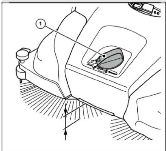
The rotary handle for adjusting the height of the disc brushes is located in the middle of the front section. The disc brushes are adjusted to the surface to be swept using the height adjustment. The levels are based on experience and should therefore be regarded as reference values. As a result, the steps may need to be adjusted during sweeping depending on the surface.
- Level 1-2: for all even, hard surfaces (e.g. asphalt, concrete, slabs...)
- Level 3-4: for damp leaves, sand, uneven surfaces (e.g. exposed aggregate concrete slabs)
• Level 5-7: for heavy soiling and more uneven surfaces
NOTE
Do not press the disc brushes too firmly onto the floor. Excessive contact pressure leads to increased wear and reduces battery life. Excessive contact pressure also increases the pushing resistance and can have a detrimental effect on the cleaning result
natural_image
Technical line drawing of a car interior showing steering wheel, dashboard, and gear shift (no text or symbols)Abb. 14: Height adjustment of the disc brush
- Set the required level:
- To do this, turn the rotary handle (1) to the left to reduce the level.
• To do this, turn the rotary handle (1) to the right to increase the level.
» Lift the appliance slightly by the handle. This makes it easier to adjust the height.
7.3 Set the hold-down device
Use the hold-down device to adjust the right-hand disc brush to the edge areas to be swept, e.g. on walls or kerbs.
NOTE
Excessive wear can occur if the hold-down device is not adjusted correctly on low edges. The down holder must not scratch the surface.
natural_image
Diagram of a car interior showing a steering wheel, dashboard, and seatbelt with no text or symbolsAbb. 15: Hold-down device adjustment
Sweeping edges and corners
- Press the handle (1) of the down holder downwards.
Operation on surfaces
- Pull the handle (1) of the down holder upwards.
7.4 Battery operation and LED display
text_image
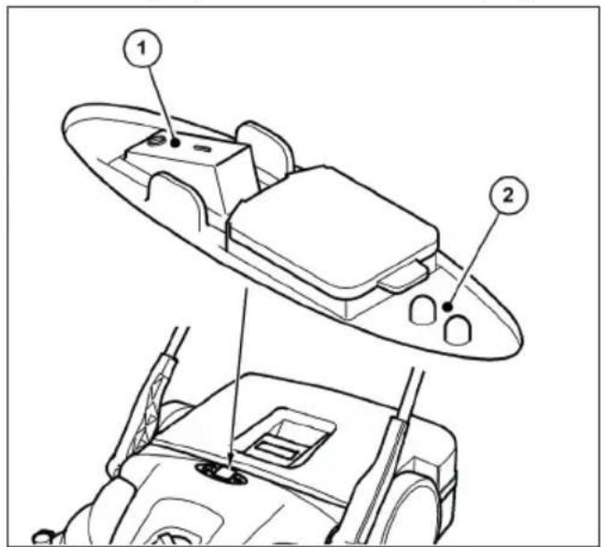
Technical diagram of a vehicle's rearview assembly with labeled parts 1 and 2Abb. 16: Operation and display
The LED display (2) provides information on the current operating status of the sweeper in battery mode.
- Place the sweeper on the surface to be swept.

CAUTION
Do not press the on/off switch with you foot.
Tilting the sweeper when starting up the disc brushes can result in injuries from falling or tripping.
- Only switch the sweeper on or off by hand
- Switch the sweeper on by pressing the on/off switch (1) to position "I".
The disc brushes and fi ne dirt sweeping roller start to rotate. If the battery is suffi ciently charged, the green LED of the LED display (2) lights up during battery operation.
Guide the appliance over the push handle with both hands.
- Push the device forward at normal walking speed.
- Switch the sweeper off by pressing the on/off switch (1) to the "0" position.
- Empty the hopper if necessary, see section "Emptying the debris container" in chapter 7.7 of these operating instructions.
» To achieve perfect sweeping results, empty the hopper at regular intervals.
NOTE
- If the disc brushes rotate more slowly or the red LED of the LED display (2) lights up during operation, this indicates that the battery charge level is low. Switch off the appliance and charge the battery.
- If the battery charge level is too low the device is switched off by the built-ir electronics. The red LED on the LED display (2) fl ashes. Switch off the device and charg the battery. Deep discharge voids the warranty!
- Clean the sweeper and dust filter at the end of work, see section „Clean the appliance“ in chapter 9.4 of these operating instructions.
- Fully recharge the battery if necessary, see section „Charge the battery“ in chapter 6.4 of these operating instructions.
7.5 Overload protection
To prevent damage, the motors are equipped with overload protection. If the sweeper's electronics switch off after a short time, this is due to an excessive load on the motors. The fine dirt sweeping roller and the disc brushes must then be checked for free movement and blockages such as jammed stones, wound-up threads and similar must be removed.
text_image
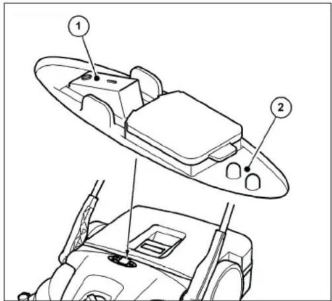
Technical diagram showing labeled components of a boat's side panel and rear view, with numbered annotations.Abb. 17: Operation and display
- After the overload protection has been triggered, switch off the sweeper's electronics by pressing the on/off switch (1) to the "0" position.
CAUTION
Risk of injury due to accidental start-up of the sweeper!
When working on the sweeper, there is a risk of being drawn in by accidentally switching on the appliance.
- Make sure that the device is not accidentally switched on while the blockage is being released! If necessary, disconnect the blue battery connection cable from the battery. See section "Disconnecting the battery connection cable" in chapter 10.2 of these operating instructions.
- Locate and remove the blockage, see section "Remove blockage" in chapter 9.2 of these operating instructions.
- If necessary, reconnect the blue battery connection cable. See section "Connecting the battery connection cable" in chapter 6.3 of these operating instructions.
- Switch the sweeper on by pressing the on/off switch to position "I"
- Check that the device is working as usual.
7.6 Manualoperation
The sweeper can also be operated temporarily without electrical support if the battery charge level is low. The sweeping mechanism is then driven by pushing the appliance.
EN
- Guide the appliance over the push handle with both hands.
- Push the device forward at normal walking speed.
- Empty the debris container if necessary, see section „Emptying the debris container“ in chapter 7.7 of these operating instructions.
- Fully recharge the battery, see section "Charge the battery" in chapter 6.4 of these operating instructions.
» Only use manual operation temporarily. A better sweeping result can be achieved in battery mode due to less effort.
7.7 Emptying the debris container

WARNING
Risk of cuts from broken glass, metal or other sharp-edged materials!
When emptying the hopper, cuts can be caused by broken glass, metal or other sharpedged materials.
- Wear the prescribed personal protective equipment!

CAUTION
Health hazard due to swept up dust!
When emptying the sweepings container, the swept up dust can pose a health hazard.
- Wear the prescribed personal protective equipment!
text_image
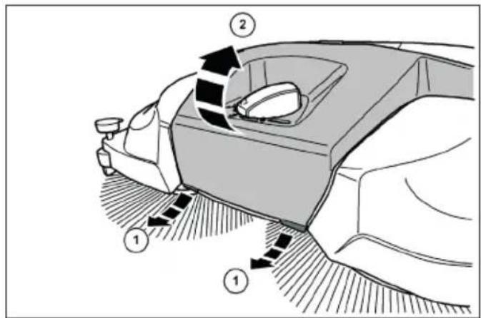
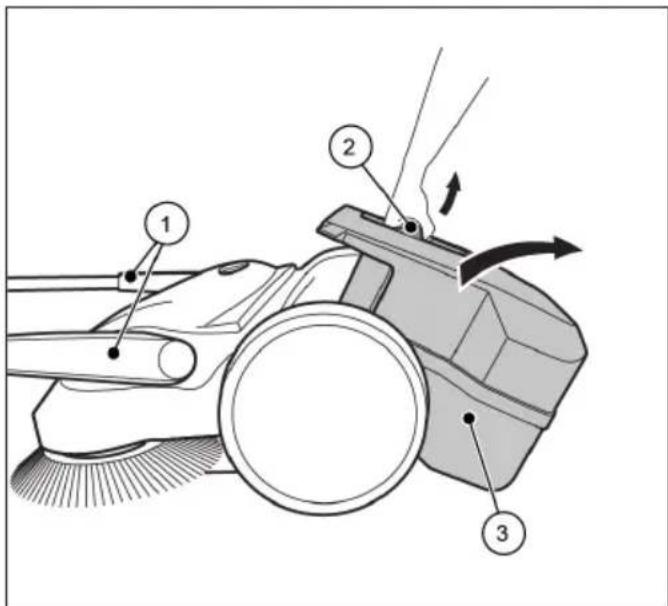
Technical diagram of a cleaning or cleaning device with numbered components and directional arrows indicating motion or flow.Abb. 18: Emptying the sweepings container
• Empty the debris container after each use.
• Empty the hopper at regular intervals to achieve perfect sweeping results.
1. Move the push handle (1) to the forward tilted position.
2. Pull the debris container (3) upwards by the container handle (2).
3. Empty the debris container (3) completely.
» Ensure that the edges of the housing are also free of dirt.
4. Insert the empty debris container (3) into the appliance.
5. Press the container handle (2) back into the starting position.
» The locking mechanism of the debris container (3) must engage audibly.
6. Return the push handle (1) to the operating position.
8. Troubleshooting

WARNING
Risk of cuts from broken glass, metal or other sharp-edged materials!
When emptying the hopper, cuts can be caused by broken glass, metal or other sharpedged materials.
- Wear the prescribed personal protective equipment!

CAUTION
Health hazard due to dust generated during sweeping!
Inhaling dust can endanger your health.
- Wear the prescribed personal protective equipment!

CAUTION
Risk of injury due to the push bar tipping over!
If the push bar tips over, this can cause minor injuries such as crushed fingers or bruising to the user or other persons.
- When carrying the device, hold it in such a way that the push bar cannot tip over.

CAUTION
Risk of injury due to accidental start-up of the sweeper!
When working on the sweeper, there is a risk of being drawn in by accidentally switching on the appliance.
- Ensure that the appliance is not accidentally switched on during troubleshooting! If necessary, disconnect the blue battery connection cable from the battery. See section "Disconnecting the battery connection cable" in chapter 10.2 of these operating instructions.
Despite observing the prescribed maintenance work and checking the appliance before use, faults may occur. Possible faults are listed in the following tables, Part 1 and Part 2, with details of the cause and remedy.
8.1 Fault table part 1
| Fault Cause Remedy | ||
| Appliance runs sluggishly or unevenly | Appliance dirty | Clean the sweeper, see chapter 9.4 in the section „Clean the appliance“ |
| Broom blocked | Remove blockage, see chapter 9.2 in the section „Remove blockage“ | |
| Brush drives contaminated | Clean brush drives, see chapter 9.4 in the section „Clean the appliance“ | |
| Height adjustment set too low | Adjust the height adjustment, see chapter 7.2 in the section „Height adjustment of the disc brushes“ | |
| Contact pressure of the disc brushes too high | ||
| Battery charge level too low. LED indicator on the sweeper lights up "red" | Charge the battery, see chapter 6.4 in the section „Charge the battery“ | |
| Disc brushes do not rotate | Contact service | |
| Fine dirt sweeping roller does not rotate | ||
| Device switches off | Contact pressure of the disc brushes too high | Adjust the height adjustment, see chapter 7.2 in the section „Height adjustment of the disc brushes“ |
| Broom blocked | Clean the sweeper, see chapter 9.4 in the section „Clean the appliance“ | |
| Overload protection active | Remove blockage, see chapter 7.5 in the section "Overload protection" | |
| Battery charge level too low. LED display on the sweeper lashes "red". Device switched off by electronics | Charging the battery, see chapter 6.4 in the section „Charge the battery“ | |
| Fuse F1 defective | Check and replace fuse F1, see chapter 8.4 in the section „Remove and check fuse F1“ | |
| Device can no longer be switched on | Fuse F1 defective | Check and replace fuse F1, see chapter 8.4 in the section „Remove and check fuse F1“ |
| Battery connection cable disconnected | Connect the battery connection cable, see chapter 6.3 in the section "Connecting the battery connection cable" | |
| Battery deeply discharged Contact service | ||
| Bristles are bent Incorrect storage | Align the bristles, see chapter 9.3 in the section „Align bristles“ |
8.2 Fault table part 2
| Fault Cause Remedy | ||
| Sweeping result insufficient | Sweeping lip is missing, loose or heavily worn | Replace sweeping lip |
| Contact pressure of the disc brushes too high | Adjust the height adjustment, see chapter 7.2 in the section „Height adjustment of the disc brushes“ | |
| Significant wear on the disc brushes | Replace disc brushes | |
| Debris container is full | Empty the debris container, see chapter 7.7 in the section „Emptying the debris container“ | |
| Improper use of the sweeper based on the information in chapter 2.2 in the section „Improper use“ | Use a suitable cleaning device or cleaning agent |
8.3 Troubleshooting Procedure

CAUTION
Risk of injury due to accidental start-up of the sweeper!
After rectifying faults on the sweeper, there is a risk of the appliance accidentally starting up.
- Before connecting the battery, make sure that the on/off switch on the device is in the "0" position.
- Set the on/off switch on the device to the "0" position.
- Disconnect the blue battery connection cable from the battery.
- Eliminate the fault according to the fault table.
- If necessary, reconnect the blue battery connection cable to the battery.
- Switch the sweeper on by pressing the on/off switch in position "I". Check that the device is working as usual.
8.4 Remove and check fuse F1
The sweeper is equipped with a 15 amp fuse to protect the electrical components. Proceed as follows to check and replace the F1 fuse:

CAUTION
Risk of injury or accident due to incorrect fuse rating!
If an incorrect fuse rating is used, the electrical components may be overloaded when the appliance is switched off, during the charging process or during operation of the appliance, resulting in smoke and fire
- Replace the fuse only with a new 15 amp fuse approved by the manufacturer.

CAUTION
Risk of injury due to accidental start-up of the sweeper!
When working on the sweeper, there is a risk of being drawn in by accidentally switching on the appliance.
- Make sure that the device is not accidentally switched on while the fuse is being removed and checked! To do this, disconnect the blue battery connection cable from the battery.
NOTE
Using a fuse with a higher or lower value can cause considerable damage to the device.
To avoid damage, only replace a blown fuse with a 15 amp fuse approved by the manufacturer. Only replace the fuse if the cause of the fault has been rectifi ec
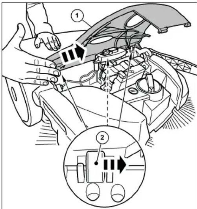
text_image
Technical diagram showing car engine compartment with labeled parts and a zoomed-in view of the internal component.Abb. 19: Removing the hood
- Set the on/off switch on the appliance to the "0" position.
-
Move the push handle to the forward tilted position, see section „Emptying the debris container“ in chapter 7.7 of these operating instructions
-
Disconnect the blue battery connection cable from the battery, see section "Disconnecting the battery connection cable" in chapter 10.2 of these operating instructions.
- Carefully unhook the cover (1) from the hinges (2) by lightly tapping the edge of the cover with the palm of your hand in the direction of the arrow.
text_image
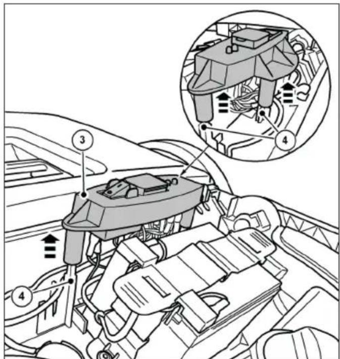
Technical diagram of a vehicle engine bay with numbered components and an inset showing internal airflow or airflow paths.Abb. 20: Removing the switch plate
- Carefully pull the switch plate (3) upwards off the guide pins (4).
- Put the switch plate (3) with the connected cables to one side.
text_image
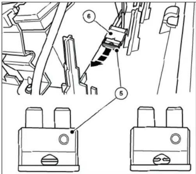
Technical diagram showing mechanical assembly with numbered components and labeled partsAbb. 21: Fuse F1
- Pull the fuse F1 (5) out of the fuse holder (6).
- Check and replace the fuse if necessary.
» The picture on the right shows a blown fuse.
» Only use a fuse with exactly 15 amps.
» Reassemble in reverse order to removal.
Please note the following:
- Fit the cover from above and then snap it into place by carefully pressing it into the hinges. Make sure that the cover is centered, otherwise the lugs of the hinges could break.
- Fully connect the blue battery connection cable to the plug-in tab on the battery.
- Switch the sweeper on by pressing the on/off switch to position "I".
- Check that the device is working as usual.
NOTE
If the fuse blows again immediately after switching on the sweeper, contact the service department. The fuses are available as spare parts from Electrostar GmbH
9. Maintenance and cleaning

WARNING
Risk of cuts from broken glass, metal or other sharp-edged materials!
When emptying the hopper, cuts can be caused by broken glass, metal or other sharpedged materials.
- Wear the prescribed personal protective equipment!

CAUTION
Health hazard due to dust generated during sweeping!
Inhaling dust can endanger your health.
- Wear the prescribed personal protective equipment!

CAUTION
Risk of injury due to the push bar tipping over!
If the push bar tips over, this can cause minor injuries such as crushed fingers or bruising to the user or other persons.
- When carrying the device, hold it in such a way that the push bar cannot tip over.

CAUTION
Danger from cleaning agents!
The agents may contain harmful components and can cause irritation to the respiratory tract and skin.
- Observe the manufacturer's safety data sheet.
- Avoid spillage and mist formation.
- Do not eat, drink or smoke while working.
- Avoid contact with skin and eyes.

CAUTION
Risk of injury due to accidental start-up of the sweeper!
During maintenance and cleaning work on the sweeper, there is a risk of being drawn in by accidentally switching on the appliance.
- The appliance must be switched off and disconnected from the power supply during all work.
- Do not carry out any work with the motor running.
- The on/off switch must be in the "0" position
- Ensure that the appliance is not accidentally switched on during maintenance and cleaning work! If necessary, disconnect the blue battery connection cable from the battery. See section "Disconnecting the battery connection cable" in chapter 10.2 of these operating instructions.
NOTE
Improper maintenance can lead to damage and shorten the service life of the sweeper
The following sections describe the maintenance and cleaning work required for optimum and trouble-free operation.
In some cases, the performance of the specified work is time and/or load-dependent. Where intervals are specified both in terms of deadlines and operating hours, the case that occurs first applies.
Contact the manufacturer if you have any questions about maintenance work and intervals.
9.1 Maintenance schedule
| Maintenance interval | Maintenance work |
| Before starting work | Check the appliance for functionality and damage. Contact the service department if necessary |
| Check that the push handle is firmly seated in the handle fittings | |
| Check the debris container for tight fit and condition | |
| Check the disc brushes and the fine dirt sweeping roller for coiled threads and cords. Remove these if necessary. | |
| Check the disc brush and the fine dirt sweeping roller for jammed parts or soiling | |
| Check the handles for dirt and clean them if necessary. | |
| Check the height adjustment for the correct height | |
| Check the sweeping pressure setting. If necessary, adjust the sweeping pressure to the surface to be swept | |
| Check that the on/off switch can be easily moved to the "0" position at any time | |
| Check the connection socket for the charger on the sweeper for foreign objects | |
| Check whether the battery charge level is sufficient for the sweeping work to be carried out. Charge the battery if necessary | |
| At the end of work | Empty the sweepings container |
| Clean the appliance | |
| Clean the dust filter | |
| Charge the battery | |
| 8 Bh Clean brush drives | |
| 2 months Charge the battery | |
9.2 Remove blockage
- Remove wound-up material (e.g. strings, threads, long-fibered materials...) from the bristles and axles.
- Remove jammed material (e.g. stones, branches, leaves...).
EN
9.3 Alignbristles

WARNING
Fire hazard due to improper handling of a blower or the use of unsuitable blowers!
There is a risk of fire when aligning the bristles if excessive temperatures are generated during heating.
- Do not use naked flames or burners to heat the bristles!
- Do not use a hot air blower. The bristles car melt if the air is too hot.
Bent bristles can be straightened by heating them with a hot air blower (e.g. hair dryer).
- Point the hot air blower that is switched on at the bent bristles.
» With sufficient heating, the bristles will straighten up again by themselves.
9.4 Clean the appliance
- Do not use any degreasing agents.
- Do not use harsh cleaning agents.
- Do not clean the appliance with a high-pressure cleaner or under running water. The appliance must not be immersed in water or wiped with water.
- Protect the bearing points from moisture.
-
Do not clean the disc brushes and fi ne dirt sweeping roller with compressed air.
» The hard jet of air can damage the bristles. -
Clean the disc brushes, fi ne dirt sweeping roller and drives with a wet cloth.
-
Clean all plastic parts with a damp cloth.
» Keep the battery clean, as a dirty battery can discharge over time due to leakage currents via the terminals.
10. Decommissioning/storage/storage
10.1 Dismantle the push handle

CAUTION
Risk of injury due to the push bar tipping over
If the push bar tips over, this can cause minor injuries such as crushed fingers or bruising to the user or other persons.
- When carrying the device, hold it in such a way that the push bar cannot tip over.
» The push handle can be removed from the device for space-saving storage.
text_image
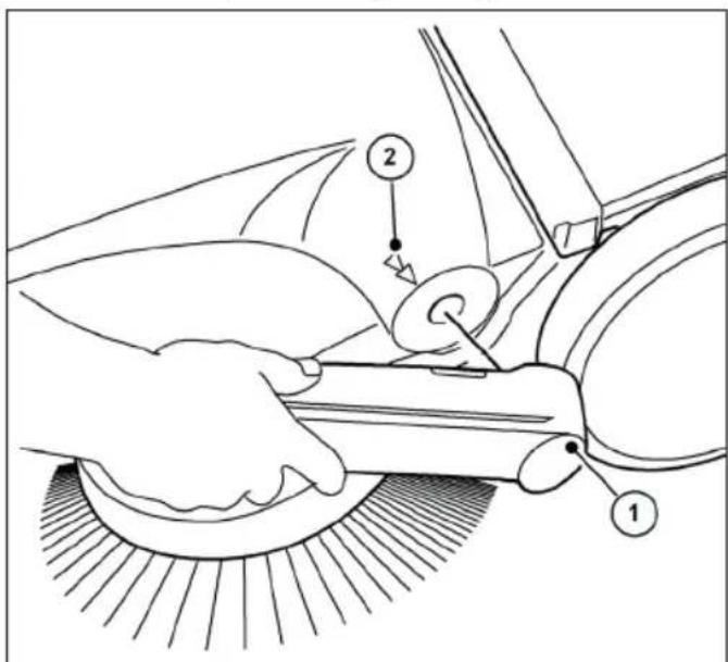
Technical diagram showing a hand operating a car wheel with labeled parts 1 and 2, likely illustrating a mechanical or cleaning process.Abb. 22: Removing the push bar
- Align the respective arrows (2) on the housing with the bar of the handle fittings (1).
- Position yourself between the push handle in front of the appliance.
- Grasp both handle fittings (1) with your hands and carefully push them outwards.
- At the same time, pull the handle fittings out of both holders on the appliance.
10.2 Disconnect the battery connection cable
To prevent deep discharge of the battery, the blue battery connection cable must be disconnected if the battery has been stored for more than approx. 2 months without recharging.
If necessary, the battery should also be disconnected when troubleshooting and removing a blockage. Protection against accidental starting of the sweeper.
For storage periods of approx. 6 months or more, the battery must also be fully charged beforehand to maintain battery performance. Information on charging the battery can be found in chapter "6.4 Charge the battery" of these operating instructions.
» Keep the battery clean, as a dirty battery can discharge over time due to leakage currents via the terminals.
text_image
Technical diagram illustrating car wheel rim and steering wheel assembly with numbered componentsAbb. 24: Disconnect the battery connection cable
- Disconnect the blue battery connection cable (3) from the plug-in tab (4) of the battery.
» Make sure that the blue battery connection cable (3) cannot make unintentional contact with the plug-in tab (4) due to external influences, such as movement of the device (see Fig. 24 Figure B).
» The red battery connection cable (5) remains connected.
- Close the cover (2) and lock it using the tabs (1).
10.3 Storage/storage
NOTE
EN
Improper storage, e.g. storing the device in a damp environment, can lead to damage to the sweeper.
» Observe the information in chapter "10.2" Disconnecting the battery connection cable" of these operating instructions.
- Only store the device when it is clean and with an empty hopper.
» For information on emptying the sweeping container, see chapter „7.7 Emptying the debris container“ and for cleaning, see chapter „9.4 Clean the appliance“ in these operating instructions.
natural_image
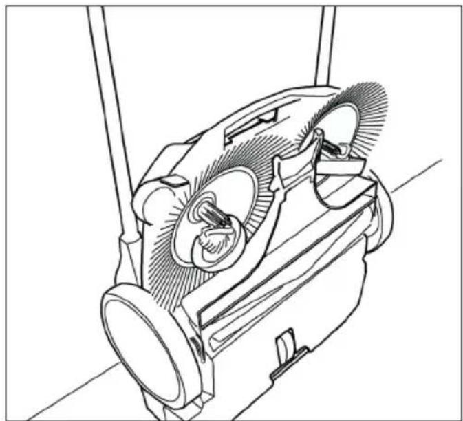
Technical line drawing of a mechanical device with gears and shafts (no text or symbols)Abb. 25: Storage position
- Position the appliance so that the bristles are not kinked or bent.
- Secure the appliance including the push handle against tipping over, slipping and damage.
- Do not store the appliance outdoors or in a damp environment.
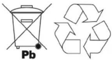
10.4 Disposal

WARNING
Environmental hazard due to incorrect disposa
Incorrect disposal of the sweeper/battery can lead to environmental pollution due to the harmful substances it contains
- Dispose of the sweeper, the charger and the battery in an environmentally friendly manner in accordance with local regulations
- Dispose of the device and the battery separately
chemical
Chemical structure of a Pb (platinum-based) recycling symbol with an accompanying recycling symbol11. REACH
REACH is the European Chemicals Regulation for the Registration, Evaluation, Authorization and Restriction of Chemicals.
Information on compliance with REACH
Regulation (EC) No. 1907/2006 can be found at www.starmix.de
12. EC Declaration of Conformity
Declaration of Conformity according to the Machinery Directive 2006/42/EC, Annex II 1A
Manufacturer:
Electrostar GmbH
Hans-Zinser-Str. 1-3
73061 Ebersbach/Fils
Germany
Authorized representative for the compilation of technical documentation:
Electrostar GmbH
Hans-Zinser-Str. 1-3
73061 Ebersbach/Fils
Germany
Product:
Hand-held, battery-powered sweeper haaga 677 plus
We hereby declare that the above-mentioned product complies with all relevant provisions of the Machinery Directive 2006/42/EC. The above product complies with the requirements of the following relevant directives:
• EMC Directive 2014/30/EU
• RoHS 2011/65/EU
The following harmonized standards have been applied:
• EN ISO 12100:2010, Safety of machinery - General principles for design - Risk assessment and risk reduction
• EN 60335-1:2012, Household and similar electrical appliances - Safety - Part 1: General requirements
- EN 60335-2-72:2012, Household and similar electrical appliances - Safety - Part 2-72: Particular requirements for floor treatment machines, with or without traction drive, for professional use
- EN 55014-1:2021, Electromagnetic compatibility - Requirements for household appliances, electric tools and similar electrical appliances - Part 1: Emission
- EN 55014-2:2021, Electromagnetic compatibility - Requirements for household appliances, electric tools and similar apparatus - Part 2: Immunity - Product family standard
• EN IEC 61000-3-2:2019
• EN 61000-3-3:2013 - EN 62233:2008-04, Methods for measuring the electromagnetic fields of household appliances and similar electrical appliances with respect to the safety of persons in electromagnetic fields.
- EN IEC 63000:2018-12, Technical documentation for the assessment of electrical and electronic equipment with respect to the restriction of hazardous substances;
Ebersbach, 16.07.2025

text_image
Candu
text_image
SremCarsten Gresser
Head of Assurancer
Table des matières
Masque anti-poussière
text_image
Technical diagram of a lawn mower with numbered parts for identification and assembly reference.text_image
Technical diagram of a mechanical assembly with numbered components labeled 14 through 17natural_image
Technical line drawing of a mechanical component with internal channels and a numbered label (18), no readable text or symbols present.text_image
Anatomical diagram of a biological structure with numbered labels pointing to specific parts.text_image
Technical diagram of a vehicle's internal components with numbered parts labeled 22, 23, and 24text_image
Technical diagram showing mechanical assembly with numbered components and a magnified inset highlighting parts 26 and 27.text_image
Technical diagram of a vacuum cleaner with labeled parts 1 and 2, showing internal components and hand placement.text_image
(1) (B) (10) (B)text_image
(I) (II) (A)text_image
Diagram of a car interior showing directional arrows and labeled parts, likely illustrating vehicle motion or steering system.text_image
Technical diagram showing two mechanical assembly steps labeled A and B, with numbered components and directional arrows indicating movement.text_image
Technical diagram of a car electrical plug with numbered components for identificationnatural_image
Technical line drawing of a car interior showing steering wheel, dashboard, and gear shift (no text or symbols)natural_image
Line drawing of a car interior showing dashboard, seatbelt, and steering wheel (no text or symbols)text_image
Technical diagram of a vehicle's front and rear views with labeled componentstext_image
Technical diagram of a boat's internal components with numbered labels pointing to different parts.text_image
Technical diagram of a cleaning or cleaning device with numbered components and directional arrows indicating motion or movement.text_image
Technical diagram showing car engine compartment with labeled parts and a zoomed-in view of the internal components.text_image
Technical diagram of a car engine showing labeled components and airflow indicatorstext_image
Technical diagram showing mechanical assembly with numbered components and labeled partsAbb. 21: Fusible F1
text_image
Technical diagram showing a hand operating a car wheel with labeled parts 1 and 2, likely illustrating a mechanical or cleaning process.text_image
Diagram of a robotic car interior with labeled parts and directional arrows indicating motion or movement.text_image
Technical diagram showing mechanical assembly steps with labeled components A and B, including numbered parts 3, 4, and 5.natural_image
Technical line drawing of a mechanical device with internal components and mounting brackets (no text or symbols)Abb. 25: Position de rangement
text_image
Technical diagram of a lawn mower with numbered parts for identificationAbb. 1: Vista general de componentes 1
text_image
Technical diagram of a mechanical assembly with numbered components labeled 14 through 17natural_image
Technical line drawing of a mechanical component with internal channels and a numbered label (18), no readable text or symbols present.text_image
Anatomical diagram of a biological structure with numbered labels pointing to specific parts.Abb. 4: Vista general de componentes 4
text_image
Technical diagram of a vehicle interior with numbered components and labeled partstext_image
Technical diagram showing mechanical assembly with numbered components and a magnified inset highlighting parts 26 and 27.text_image
Technical diagram of a vacuum cleaner with labeled parts 1 and 2, showing mechanical components and hand positioning.Abb. 7: Transporte del aparato
text_image
(1) (B) (10) (B)text_image
(I) (II) (A)text_image
Diagram of a car interior showing labeled parts and directional arrows indicating movement or flowtext_image
Technical diagram showing two mechanical assembly steps labeled A and B, with numbered components and directional arrows indicating movement.text_image
Technical diagram of a car's electrical fuse and power tool with numbered componentsnatural_image
Technical line drawing of a car interior showing steering wheel, dashboard, and gear shift (no text or symbols)natural_image
Line drawing of a car interior showing the seat, dashboard, and steering wheel (no text or symbols)text_image
Technical diagram of a boat's internal components with numbered labels pointing to different parts.text_image
Technical diagram of a boat's internal components with numbered labels pointing to different parts.text_image
Technical diagram of a cleaning or cleaning device with numbered components and directional arrows indicating motion or movement.text_image
Technical diagram showing car engine compartment with labeled parts and a zoomed-in view of the internal components.text_image
Technical diagram of a vehicle engine showing labeled components and airflow indicatorstext_image
Technical diagram showing mechanical assembly with numbered components and labeled partsAbb. 21: Fusible F1
text_image
Technical diagram showing a hand using a tool to clean or repair a car, labeled with parts 1 and 2.text_image
Diagram illustrating a robotic arm mechanism with labeled parts and directional arrows indicating motion or movement.Abb. 23: Apertura del capó
text_image
Technical diagram showing mechanical assembly steps with labeled components A and B, including numbered parts 3, 4, 5.natural_image
Technical line drawing of a mechanical device with no visible text or symbolschemical
Chemical symbol and its corresponding recycling symbol: a Pb-branded waste bin with crossbones and a recycling symbol with arrows.11. REACH
text_image
Technical diagram of a lawn mower with numbered parts for identification and assembly reference.text_image
Technical diagram of a mechanical assembly with numbered components labeled 14 through 17Abb. 2: Vista geral dos componentes 2
| Item n°. Componente |
| 14 Rolo de varrimento de sujidade fina |
| 15 Aresta biselada |
| 16 Lábio de varrimento |
| 17 Placa de varrimento |
natural_image
Technical line drawing of a mechanical component with internal channels and a numbered label (18), no readable text or symbols present.text_image
Anatomical diagram of a biological structure with numbered labels pointing to specific parts.text_image
Technical diagram of a car interior with numbered components and labeled partstext_image
Technical diagram showing mechanical assembly with numbered components and a magnified inset highlighting parts 26 and 27.text_image
Technical diagram of a vacuum cleaner with labeled parts 1 and 2, showing internal components and hand placement.Abb. 7: Transporte do aparelho
text_image
(1) (B) (10) (B)text_image
(I) (II) (A)text_image
Diagram of a car interior showing directional arrows and labeled parts, likely illustrating motion or movement in vehicle dynamics.text_image
Technical diagram showing two mechanical assembly steps labeled A and B, with numbered components and directional arrows indicating movement.text_image
Technical diagram of a car electrical plug assembly with numbered parts labeled 1 to 4Abb. 13: Ligar o carregador
natural_image
Technical line drawing of a car interior showing steering wheel, dashboard, and gear shift (no text or symbols)natural_image
Line drawing of a car interior showing steering wheel, dashboard, and seat area (no text or symbols)text_image
Technical diagram of a vehicle's rearview assembly with labeled parts 1 and 2text_image
Technical diagram of a boat's internal components with numbered labels pointing to different parts.text_image
Technical diagram of a cleaning or cleaning device with numbered components and directional arrows indicating motion or flow.Abb. 18: Esvaziar o contentor
text_image
Technical diagram showing car engine compartment with labeled parts and a zoomed-in view of the internal component.text_image
Technical diagram of a car engine showing labeled components and airflow indicators, including a zoomed-in inset of the engine's internal structure.text_image
Technical diagram showing mechanical assembly with numbered components and labeled partsAbb. 21: Fusível F1
9.3 Alinhar as cerdas

ATENÇÃO
text_image
Technical diagram showing a hand operating a tool with labeled parts 1 and 2, likely illustrating a machining or cleaning process.Abb. 22: Retirar a barra de empurrar
text_image
Diagram of a car interior showing labeled parts and directional arrows indicating movement or flownatural_image
Technical line drawing of a mechanical device with no visible text or symbolschemical
Chemical symbol and its corresponding recycling symbol: a phosphorus atom (Pb) with crossed-out lines next to a recycling symbol.11. REACH
text_image
Technical diagram of a lawn mower with numbered parts for identification and assembly reference.IT
text_image
Technical diagram of a mechanical assembly with numbered components labeled 14 through 17natural_image
Technical line drawing of a mechanical component with internal channels and a numbered label (18), no readable text or symbols present.text_image
Anatomical diagram of a biological structure with numbered labels pointing to specific parts.text_image
Technical diagram of a vehicle interior with numbered components and labeled partstext_image
Technical diagram showing mechanical assembly with numbered components and a magnified detail view highlighting parts 26 and 27.text_image
Technical diagram of a vacuum cleaner with labeled parts 1 and 2, showing internal components and motion indicators.text_image
(1) (B) (10) (B)text_image
(I) (II) (A)text_image
Diagram of a car interior showing directional arrows and labeled parts, likely illustrating motion or flow in vehicle dynamics.Abb. 11: Apertura del coperchio

ATTENZIONE
text_image
Technical diagram showing two mechanical assembly steps labeled A and B, with numbered components and directional arrows indicating movement.text_image
Technical diagram of a car electrical fuse with numbered components labeled 1 to 4natural_image
Technical diagram of a car interior showing steering wheel, dashboard, and gear shift (no text or labels)natural_image
Technical line drawing of a car interior showing dashboard, seatbelt, and steering wheel (no text or symbols)text_image
Technical diagram of a boat's internal components with numbered labels pointing to different parts.text_image
Technical diagram of a vehicle's front and rear views with labeled componentstext_image
Technical diagram of a cleaning or cleaning device with numbered components and directional arrows indicating motion or flow.text_image
Technical diagram showing car engine compartment with labeled parts and a close-up of the internal component, likely illustrating a valve or valve mechanism.text_image
Technical diagram of a car engine showing labeled components and airflow indicatorstext_image
Technical diagram showing mechanical assembly with numbered components and labeled partsAbb. 21: Fusibile F1
text_image
Technical diagram showing a hand operating a car wheel with labeled parts 1 and 2, likely illustrating a mechanical or cleaning process.text_image
Diagram of a car interior showing labeled parts and motion arrows, likely illustrating steering or maneuvering motion.text_image
Technical diagram showing mechanical assembly steps with labeled components A and B, including numbered parts 3, 4, and 5.natural_image
Technical line drawing of a mechanical device with no visible text or symbolschemical
Chemical symbol and its corresponding recycling symbol: a Pb-branded waste bin with crossbones and a recycling symbol.1.2 Conventies....192
1.3 Symbolen en etikettering.... 192
7.5 Overbelastingsbeveiliging....208
7.6 Handmatige bediening....209
text_image
Technical diagram of a lawn mower with numbered parts for identification and assembly reference.text_image
Technical diagram of a mechanical assembly with numbered components labeled 14 to 17natural_image
Technical line drawing of a mechanical component with internal channels and a numbered label (18), no readable text or symbols present.text_image
Anatomical diagram of a biological structure with numbered labels pointing to specific parts.Abb. 4: Overzicht componenten 4
text_image
Technical diagram of a car interior with numbered components and labeled partsAbb. 5: Overzicht componenten 5
text_image
Technical diagram showing mechanical assembly with numbered components and a magnified inset highlighting parts 26 and 27.text_image
Technical diagram of a vacuum cleaner with labeled parts 1 and 2, showing mechanical components and hand interaction.text_image
(1) (B) (10) (B)Abb. 8: Montage van de handgreepbevestigingen
text_image
(I) (II) (A)text_image
Diagram of a car interior showing directional arrows and labeled parts, likely illustrating vehicle or mechanical components.text_image
Technical diagram showing mechanical assembly steps labeled A and B, with numbered components 3, 4, and 5 indicating different parts of a device.text_image
Technical diagram of a car's electrical switch assembly with numbered componentstext_image
Technical diagram showing a mechanical assembly with labeled component 1 and directional arrows indicating motion or force.natural_image
Technical line drawing of a car interior showing a valve and seat, with no visible text or symbols.text_image
Technical diagram showing a mechanical component with labeled parts, including a top view and side view.Abb. 16: Bediening en display
text_image
Technical diagram of a boat's internal components with numbered labels pointing to different parts.Abb. 17: Bediening en display
text_image
Technical diagram of a cleaning or cleaning device with numbered components and directional arrows indicating motion or flow.Abb. 18: Vuilcontainer legen
text_image
Technical diagram showing car engine compartment with labeled parts and a zoomed-in view of the internal component.text_image
Technical diagram of a car engine showing labeled components and airflow indicatorstext_image
Technical diagram showing mechanical assembly with numbered components and labeled partsAbb. 21: Zekering F1
text_image
Technical diagram showing a hand operating a car wheel with labeled parts 1 and 2, likely illustrating a mechanical or cleaning process.text_image
Technical diagram illustrating three stages of a car wheel rim assembly with labeled parts and directional arrows.natural_image
Technical line drawing of a mechanical device with no visible text or symbolsAbb. 25: Opslagpositie
chemical
Chemical symbol and its corresponding recycling symbol: a Pb-branded waste bin with crossbones and a recycling symbol with arrows.NL
11. REACH
text_image
Technical diagram of a lawn mower with numbered parts for identificationAbb. 1: Oversigt over komponenter 1
text_image
Technical diagram of a mechanical assembly with numbered components labeled 14 through 17Abb. 2: Oversigt over komponenter 2
text_image
Anatomical diagram of a biological structure with numbered labels pointing to specific parts.Abb. 4: Oversigt over komponenter 4
Vare nr. Komponent
natural_image
Technical line drawing of a mechanical component with internal channels and a numbered label (18), no readable text or symbols present.Abb. 3: Oversigt over komponenter 3
Vare nr. Komponent
19 Koblingshus
20 Tandbøsningen
21 Spiralformet gearing
text_image
Technical diagram of a car interior with numbered components and labeled partsAbb. 5: Oversigt over komponenter 5
Vare nr. Komponent
18 Typeplade
text_image
Technical diagram showing mechanical assembly with numbered components and a magnified inset highlighting parts 26 and 27.Abb. 6: Oversigt over komponenter 6
| Vare nr. Komponent |
| 25 Afbryderplade |
| 26 Sikringsholder |
| 27 Sikring F1 |
text_image
Technical diagram of a vacuum cleaner with labeled parts 1 and 2, showing mechanical components and hand positioning.text_image
(1) (10) (B) (B)text_image
(I) (II) (A)Abb. 9: Montering af skubbestangen
text_image
Diagram of a car interior showing directional arrows and labeled parts, likely illustrating vehicle motion or steering system.text_image
Technical diagram showing two mechanical assembly steps labeled A and B, with numbered components and directional arrows indicating movement.text_image
Technical diagram of a car's electrical switch assembly with numbered componentsnatural_image
Technical line drawing of a mechanical component with no visible text or symbolsnatural_image
Line drawing of a car interior showing a hand operating the steering wheel (no text or symbols)text_image
Technical diagram of a vehicle's rearview assembly with labeled parts 1 and 2text_image
Technical diagram of a boat's internal components with numbered labels pointing to different parts.text_image
Technical diagram of a mechanical device with numbered components and directional arrows indicating motion or movement.text_image
Technical diagram showing car engine compartment with labeled parts and a zoomed-in view of the internal component.Abb. 19: Afmontering af motorhjelmen
text_image
Technical diagram of a car engine bay with numbered components and an inset showing internal wiring or wiring connections.text_image
Technical diagram showing mechanical assembly with numbered components and labeled partsAbb. 21: Sikring F1
text_image
Technical diagram showing a hand operating a car wheel with labeled parts 1 and 2, likely illustrating a mechanical or cleaning process.text_image
Technical diagram illustrating car wheel assembly and component disassembly, labeled with numbered steps 1 to 5.natural_image
Technical line drawing of a mechanical device with no visible text or symbolsAbb. 25: Opbevaringsposition
chemical
Chemical symbol and its corresponding representation of a Pb-based waste bin and a recycling symbol11. REACH
text_image
Technical diagram of a lawn mower with numbered parts for identification and assembly reference.text_image
Technical diagram of a mechanical assembly with numbered components labeled 14 to 17natural_image
Technical line drawing of a mechanical component with internal channels and a numbered label (18), no readable text or symbols present.text_image
Anatomical diagram of a biological structure with numbered labels pointing to specific parts.text_image
Technical diagram of a vehicle's internal components with numbered parts labeled 22, 23, and 24text_image
Technical diagram showing mechanical assembly with numbered components and a magnified inset highlighting parts 26 and 27.text_image
Technical diagram of a vacuum cleaner with labeled parts 1 and 2, showing mechanical components and hand placement.text_image
(1) (B) (10) (B)text_image
(I) (II) (A)Abb. 9: Montering av körhandtaget
text_image
Diagram illustrating a robotic arm mechanism with labeled parts and directional arrows indicating motion or movement.text_image
Technical diagram showing two mechanical assembly steps labeled A and B, with numbered components and directional arrows indicating movement.text_image
Technical diagram of a car's electrical switch assembly with numbered componentsAbb. 13: Ansluta laddaren
natural_image
Technical line drawing of a car interior showing steering wheel, dashboard, and gear shift (no text or symbols)natural_image
Line drawing of a car interior showing a hand valve and seat, with no visible text or symbolstext_image
Technical diagram showing a mechanical component with labeled parts, including a top view and side view.text_image
Technical diagram of a boat's internal components with numbered labels pointing to different parts.text_image
Technical diagram of a cleaning or cleaning device with numbered components and directional arrows indicating flow or movement.text_image
Technical diagram showing car engine compartment with labeled parts and a zoomed-in view of the component's internal structure.text_image
Technical diagram of a car engine bay with numbered components and an inset showing internal wiring or wiring connections.text_image
Technical diagram showing mechanical assembly with numbered components and labeled partsAbb. 21: Säkring F1
text_image
Technical diagram showing a hand operating a car wheel with labeled parts 1 and 2, likely illustrating a mechanical or cleaning process.text_image
Diagram of a car interior showing labeled parts and directional arrows indicating movement or flowtext_image
Technical diagram showing mechanical assembly steps with labeled components A and B, including numbered parts 3, 4, and 5.natural_image
Technical line drawing of a mechanical device with no visible text or symbolschemical
Chemical symbols for a waste bin and a recycling symbol11. REACH
text_image
Technical diagram of a lawn mower with numbered parts for identification and assembly reference.Abb. 1: Oversikt over komponenter 1
text_image
Technical diagram of a mechanical assembly with numbered components labeled 14 to 17Abb. 2: Oversikt over komponenter 2

text_image
Anatomical diagram of a biological structure with numbered labels pointing to specific parts.Abb. 4: Oversikt over komponenter 4
| Artikkelnr. Komponent | |
| 14 Feievalse for fint smuss | |
| 15 Avfaset kant | |
| 16 Feieleppe | |
| 17 Feieplate |
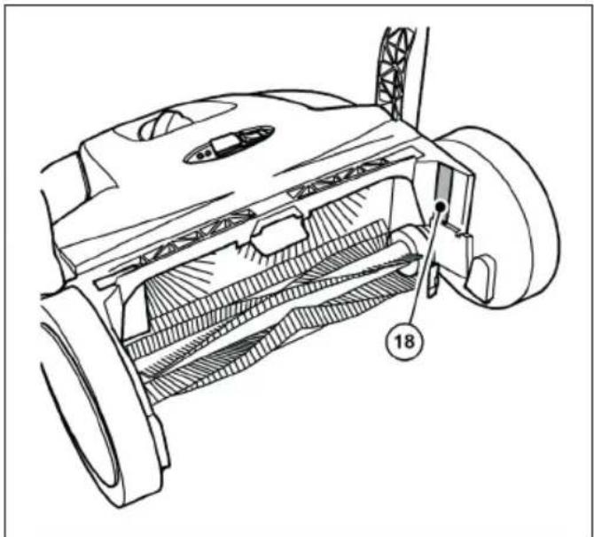
natural_image
Technical line drawing of a mechanical component with internal channels and a numbered label (18), no readable text or symbols present.Abb. 3: Oversikt over komponenter 3
| Artikkelnr. Komponent | |
| 19 Koblingshus | |
| 20 Tannhylse | |
| 21 Spiralformet giring |
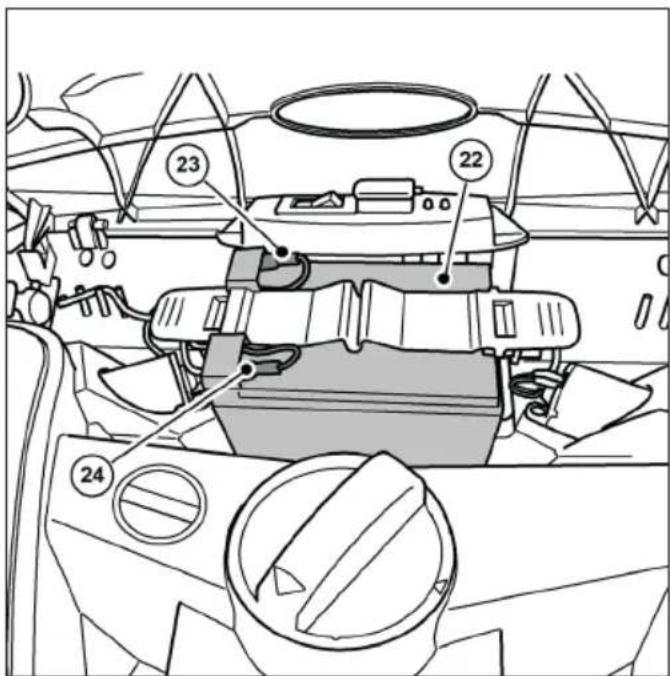
text_image
Technical diagram of a vehicle dashboard with numbered components and labeled partstext_image
Technical diagram showing mechanical assembly with numbered components and a magnified inset highlighting parts 26 and 27.text_image
Technical diagram of a vacuum cleaner with labeled parts 1 and 2, showing internal components and hand placement.text_image
(1) (B) (10) (B)text_image
(I) (II) (A)text_image
Diagram illustrating vehicle steering wheel and steering wheel movement with numbered annotationstext_image
Technical diagram showing two mechanical assembly steps labeled A and B, with numbered components and directional arrows indicating movement.text_image
Technical diagram of a car electrical fuse with numbered components for identificationAbb. 13: Koble til laderen
» Det anbefales å lade batteriet helt opp før apparatet tas i bruk for første gang.
» Laderen (3) har en helelektronisk spennings- og strømbegrenser. Dette betyr at et tilkoblet batteri alltid holdes på det optimale ladenivået. Dette forhindrer at batteriet blir overladet.
» For å lade batteriet må batteriets tilkoblingskabler være riktig tilkoblet. Informasjon om tilkobling av batteriet fi nner du i kapittel "6.3 Koble til batteriets tilkoblingskabel" i denne bruksanvisningen.
MERK
- Feiemaskinen må ikke være slått på under ladeprosessen. Dette kan føre til skader på feiemaskinens elektriske komponenter.
-
Før lading må støpselet til ladeapparatet og tilkoblingskontakten på feiemaskinen kontrolleres for fremmedlegemer, f.eks. elektrisk ledende gjenstander. Skader på apparatet på grunn av kortslutning og kabelbrann.
-
Äpne beskyttelseshetten (1) på ladekontakten på feiemaskinen.
- Sett støpselet (2) til laderen (3) inn i ladekontakten på feiemaskinen.
- Koble nettkabelen til laderen (3) til et 100-240 V strømuttak.
» Under ladeprosessen lyser LED-indikatoren (4) på laderen "oransje". Når batteriet er fulladet, skifter LED-indikatoren (4) på laderen til "grønn".
» Ladetiden avhenger i hovedsak av SOC-verdien (ladetilstanden) som batteriet har før ladeprosessen begynner. Hvis batteriet ikke lades over en lengre periode, synker ladetilstanden, noe som øker ladetiden. En full opplading kan ta opptil ca. 7 timer. Se informasjonen på ytteremballasjen eller på klistremerket som er festet på feiemaskinen før levering.
MERK
natural_image
Technical line drawing of a car interior showing steering wheel, dashboard, and gear shift (no text or symbols)natural_image
Line drawing of a car interior showing a valve mechanism and a boat (no text or symbols)text_image
Technical diagram showing a mechanical component with labeled parts, including a top view and side views.text_image
Technical diagram of a boat's internal components with numbered labels pointing to different parts.text_image
Technical diagram of a mechanical device with numbered components and directional arrows indicating motion or movement.text_image
Technical diagram showing car engine compartment with labeled parts and a zoomed-in view of the internal component.text_image
Technical diagram of a car engine bay with numbered components and an inset showing internal wiring or wiring connections.Abb. 20: Fjerne bryterplaten
text_image
Technical diagram showing mechanical assembly with numbered components and labeled partsAbb. 21: Sikring F1
- Trekk sikringen F1 (5) ut av sikringsholderen (6).
- Kontroller og bytt sikringen om nødvendig.
text_image
Technical diagram showing a hand operating a car wheel with labeled parts 1 and 2, likely illustrating a mechanical or cleaning process.text_image
Technical diagram illustrating car wheel steering and steering mechanism with labeled components and motion arrowsnatural_image
Technical line drawing of a mechanical device with gears and levers (no text or symbols)NO
chemical
Chemical symbol and recycling symbol: a phosphorus atom (Pb) with crossed-out electrons and a recycling symbol.11. REACH
Leder for Assurancer
Sisällysluettelo
text_image
Technical diagram of a lawn mower with numbered parts for identification and assembly reference.text_image
Technical diagram of a mechanical assembly with numbered components labeled 14 through 17natural_image
Technical line drawing of a mechanical component with internal channels and a numbered label (18), no readable text or symbols present.text_image
Anatomical diagram of a biological structure with numbered labels pointing to specific parts.text_image
Technical diagram of a car interior with numbered components and labeled partstext_image
Technical diagram showing mechanical assembly with numbered components and a magnified inset highlighting parts 26 and 27.text_image
Technical diagram of a vacuum cleaner with labeled parts 1 and 2, showing mechanical components and hand interaction.text_image
(1) (B) (10) (B)Abb. 8: Kahvan varusteiden asentaminen
text_image
(I) (II) (A)text_image
Diagram illustrating vehicle steering wheel and steering wheel movement with numbered annotationstext_image
Technical diagram showing two mechanical assembly steps labeled A and B, with numbered components and directional arrows indicating movement.text_image
Technical diagram of a car's electrical switch assembly with numbered componentsnatural_image
Technical line drawing of a car interior showing steering wheel, dashboard, and gear shift (no text or symbols)natural_image
Line drawing of a car interior showing dashboard, steering wheel, and seat (no text or symbols)text_image
Technical diagram showing a mechanical assembly with labeled parts, including component 1 and component 2.text_image
Technical diagram of a boat's internal components with numbered labels pointing to different parts.text_image
Technical diagram of a cleaning or cleaning device with numbered components and directional arrows indicating motion or flow.text_image
Technical diagram showing car engine compartment with labeled parts and a zoomed-in view of the internal component.Abb. 19: Konepellin irrottaminen
text_image
Technical diagram of a car engine bay with numbered components and an inset showing internal wiring connections.Abb. 20: Kytkinlevyn irrottaminen
text_image
Technical diagram showing mechanical assembly with numbered components and labeled partsAbb. 21: Sulake F1
text_image
Technical diagram showing a hand using a tool to clean or repair a car, labeled with parts 1 and 2.text_image
Diagram of a robotic car interior with labeled parts and motion arrows indicating movement or flow.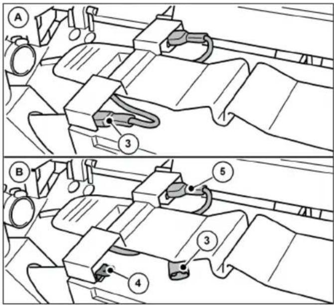
text_image
A 3 B 5 3 4natural_image
Technical line drawing of a mechanical device with gears and shafts (no text or symbols)Abb. 25: Varastointiasento
chemical
Chemical symbols for a Pb-based waste bin and a recycling symbol11. REACH
text_image
Technical diagram of a lawn mower with numbered parts for identification and assembly reference.text_image
Technical diagram of a mechanical assembly with numbered components labeled 14 through 17text_image
Anatomical diagram of a biological structure with numbered labels pointing to specific parts.natural_image
Technical line drawing of a mechanical component with internal channels and a numbered label (18), no readable text or symbols present.text_image
Technical diagram of a car interior with numbered components and labeled partstext_image
Technical diagram showing mechanical assembly with numbered components and a magnified inset highlighting parts 26 and 27.text_image
Technical diagram of a vacuum cleaner with labeled parts 1 and 2, showing mechanical components and hand interaction.text_image
(1) (B) (10) (B)text_image
(I) (II) (A)text_image
Diagram of a car interior showing directional arrows and labeled parts, likely illustrating motion or flow in a vehicle's dashboard.text_image
Technical diagram showing two mechanical assembly steps labeled A and B, with numbered components and directional arrows indicating movement.text_image
Technical diagram of a car electrical fuse with numbered components labeled 1 to 4natural_image
Technical line drawing of a car interior showing steering wheel, dashboard, and gear shift (no text or symbols)natural_image
Line drawing of a car interior showing dashboard, seatbelt, and steering wheel (no text or symbols)text_image
Technical diagram of a vehicle's internal components with numbered labels pointing to parts like the dashboard and steering wheel.text_image
Technical diagram of a boat's internal components with numbered labels pointing to different parts.text_image
Technical diagram of a mechanical device with numbered components and directional arrows indicating motion or movement.text_image
Technical diagram showing car engine compartment with labeled parts and a zoomed-in view of the internal component.text_image
Technical diagram of a car engine bay with numbered components and an inset showing internal components with arrows and labels.text_image
Technical diagram showing mechanical assembly with numbered components and labeled partsAbb. 21: Sigorta F1
text_image
Technical diagram showing a hand operating a car wheel with labeled parts 1 and 2text_image
Diagram illustrating a robotic arm mechanism with labeled parts and directional arrows indicating motion or movement.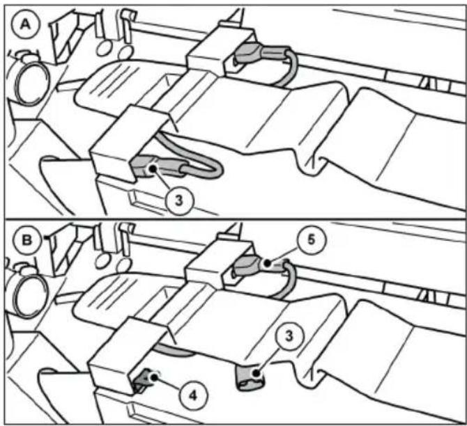
text_image
Technical diagram showing mechanical assembly steps with labeled components A, B, and numbered parts 3, 4, 5natural_image
Technical line drawing of a mechanical device with no visible text or symbolsAbb. 25: Depolama konumu
text_image
Technical diagram of a lawn mower with numbered parts for identificationtext_image
Technical diagram of a mechanical assembly with numbered components labeled 14 through 17natural_image
Technical line drawing of a mechanical component with internal channels and a numbered label (18), no readable text or symbols present.text_image
Anatomical diagram of a biological structure with numbered labels pointing to specific parts.text_image
Technical diagram of a vehicle interior with numbered components and labeled partstext_image
Technical diagram showing mechanical assembly with numbered components and a magnified inset highlighting parts 26 and 27.text_image
Technical diagram of a mechanical device with labeled parts, showing hand positioning and component alignment.text_image
(1) (B) (10) (B)text_image
(I) (II) (A)text_image
Diagram illustrating vehicle steering wheel and steering wheel movement with numbered annotationstext_image
Technical diagram showing two mechanical assembly steps labeled A and B, with numbered components and directional arrows indicating movement.text_image
Technical diagram of a car's electrical switch assembly with numbered componentsnatural_image
Technical diagram of a car interior showing steering wheel, dashboard, and gear shift (no text or labels)natural_image
Technical line drawing of a car interior showing seat, dashboard, and steering wheel (no text or symbols)text_image
Technical diagram showing two views of a vehicle's front-mounted device with labeled parts 1 and 2text_image
Technical diagram of a vehicle's front and rear views with labeled componentstext_image
Technical diagram of a mechanical device with numbered components and directional arrows indicating motion or movement.text_image
Technical diagram showing car engine compartment with labeled parts and a zoomed-in view of the internal component.text_image
Technical diagram of a car engine showing labeled components and airflow indicators, including parts numbered 3, 4, and 4.text_image
Technical diagram showing mechanical assembly with numbered components and labeled partstext_image
Technical diagram showing a hand operating a car wheel with labeled parts 1 and 2, likely illustrating a mechanical or cleaning process.text_image
Diagram of a car interior showing labeled parts and directional arrows indicating movement or flow
text_image
Technical diagram showing mechanical assembly steps with labeled components A and B, including numbered parts 3, 4, and 5.natural_image
Technical line drawing of a mechanical device with no visible text or symbolschemical
Chemical symbol and its corresponding recycling symbol: a Pb-related waste bin with crossed lines and a recycling symbol.11. REACH
text_image
Technical diagram of a lawn mower with numbered parts for identification and assembly reference.text_image
Technical diagram of a mechanical assembly with numbered components labeled 14 through 17natural_image
Technical line drawing of a mechanical component with internal channels and a numbered label (18), no readable text or symbols present.text_image
Anatomical diagram of a biological structure with numbered labels pointing to specific parts.text_image
Technical diagram of a vehicle's internal components with numbered parts labeled 22, 23, and 24text_image
Technical diagram showing mechanical assembly with numbered components and a magnified detail view highlighting parts 26 and 27.text_image
Technical diagram of a vacuum cleaner with labeled parts 1 and 2, showing internal components and hand placement.text_image
(1) (B) (10) (B)text_image
(I) (II) (A)text_image
Diagram of a car interior showing directional arrows and labeled parts, likely illustrating vehicle motion or steering system.text_image
Technical diagram showing two mechanical assembly steps labeled A and B, with numbered components and directional arrows indicating movement.text_image
Technical diagram of a car electrical fuse with numbered components labeled 1 to 4natural_image
Technical line drawing of a car interior showing steering wheel, dashboard, and gear shift (no text or symbols)natural_image
Line drawing of a car interior showing dashboard, seatbelt, and steering wheel (no text or symbols)text_image
Technical diagram showing a mechanical assembly with labeled parts, including component 1 and component 2.text_image
Technical diagram of a boat's internal components with numbered labels pointing to different parts.text_image
Technical diagram of a cleaning or cleaning device with numbered components and directional arrows indicating motion or movement.text_image
Technical diagram showing car engine compartment with labeled parts and a zoomed-in view of the internal components.Abb. 19: Demontáž kapoty
text_image
Technical diagram of a car engine bay with numbered components and an inset showing internal wiring or wiring connections.text_image
Technical diagram showing mechanical assembly with numbered components and labeled partstext_image
Technical diagram showing a hand operating a car wheel with labeled parts 1 and 2text_image
Diagram of a car interior showing labeled parts and directional arrows indicating movement or flowtext_image
Technical diagram showing mechanical assembly steps with labeled components A and B, including numbered parts 3, 4, 5.natural_image
Technical line drawing of a mechanical device with gears and shafts (no text or symbols)chemical
Chemical symbol and its corresponding representation of a Pb-based waste bin and a recycling symbol11. REACH
text_image
Technical diagram of a lawn mower with numbered parts for identification and assembly reference.text_image
Technical diagram of a mechanical assembly with numbered components labeled 14 through 17natural_image
Technical line drawing of a mechanical component with internal channels and a numbered label (18), no readable text or symbols present.text_image
Anatomical diagram of a mechanical or biological structure with numbered labels pointing to specific parts.text_image
Technical diagram of a vehicle interior with numbered components and labeled partstext_image
Technical diagram showing mechanical assembly with numbered components and a magnified inset highlighting parts 26 and 27.text_image
Technical diagram of a vacuum cleaner with labeled parts 1 and 2, showing internal components and hand positioning.text_image
(1) (B) (10) (B)text_image
(I) (II) (A)Abb. 9: Установка штанги