
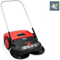
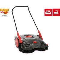
697 - Sweeper Starmix - Free user manual and instructions
Find the device manual for free 697 Starmix in PDF.

| Product type | Motorized sweeper with collection |
| Brand | Starmix |
| Model | 697 |
| Sweeping width | 970 mm |
| Sweeping capacity | 4 100 m²/h |
| Waste bin capacity | 40 L |
| Total weight | 22 kg |
| Power supply | Li-ion battery 12 V / 14 Ah |
| Nominal runtime | 90 minutes |
| Charger | 230 V AC / 50 Hz, output 12 V / 3 A |
| Sound level (pressure) | 64 dB(A) |
| Sound level (power) | 80 dB(A) |
| Vibrations (handle) | < 2.5 m/s² |
| Brush height adjustment | 7 levels (level 1-7) |
| Main functions | Motorized sweeping, manual mode, strain relief adjustment, overload protection, LED display |
| Routine maintenance | Empty bin after each use, clean dust filter, charge battery |
| Safety | Emergency stop by switch, 15 A fuse, detailed safety instructions |
| Spare parts | Rotating brushes, small debris roller, filters, accumulator, charger, retractable handle |
| Recommended use | Hard and flat surfaces (asphalt, concrete, tile) for commercial use (hotels, schools, offices) |
| Operating temperature | -10 °C to 40 °C |
Frequently Asked Questions - 697 Starmix
User questions about 697 Starmix
0 question about this device. Answer the ones you know or ask your own.
Ask a new question about this device
Download the instructions for your Sweeper in PDF format for free! Find your manual 697 - Starmix and take your electronic device back in hand. On this page are published all the documents necessary for the use of your device. 697 by Starmix.
USER MANUAL 697 Starmix
natural_image
Line drawing of a manual lawn mower with grass blades (no text or symbols)
Sprachverzeichnis
starmix 697
starmix
EN Operating instructions 33
natural_image
Technical line drawing of a mechanical device with no visible text or symbols1.2 Conventions....35
1.3 Symbols and labels....35
1.4 Limitation of Liability 35
1.5 Warranty 35
1.6 Copyright 36
1.7 Target group....36
- Safety 36
2.1 Intended use 36
2.2 Inappropriate use 36
2.3 Responsibility of the user .... 36
2.4 General safety instructions....37
2.5 General safety instructions for battery, charging socket, and charger.... 37
2.6 Hazard notices on the device....39
2.7 Personal Safety Equipment....39
-
Technical data....40
-
Construction and Function 41
-
Transport/transporting....43
5.1 Delivery 43
5.2 Scope of supply....43
5.3 Handling Packaging Materials 43
5.4 Storage of sweeping machine....43
5.5 Carrying the device 44
5.6 Transporting the device in a vehicle 44
- Commissioning 45
6.1 Install push bar....45
6.2 Connect battery leads 45
6.3 Charging battery....46
- Operation 47
7.1 Before starting work 47
7.2 Height adjustment of the plate brooms....48
7.3 Set hold-down device 49
7.4 Battery operation and LED display 49
7.5 Overload protection 50
7.6 Manual operation....51
7.7 Empty sweeping container....51
- Troubleshooting 52
8.1 Fault table Part 1 ....53
8.2 Fault table Part 2 ....54
8.3 Trouble-shooting procedure 55
8.4 Take out the F1 fuse and check 55
- Maintenance and cleaning....57
9.1 Maintenance plan 58
9.2 Clean dust filter 58
9.3 Remove blockage....58
EN
9.4 Align bristles....59
9.5 Clean the device 59
10. Decommissioning for Storage/Safekeeping 59
10.1 Disassemble push bar 59
10.2 Disconnect battery leads....60
10.3 Storage/Safekeeping....61
10.4 Disposal 61
11. REACH....62
12. EU Declaration of Conformity 62
1. General
This operating manual applies to starmix 697 sweeping machine (year of manufacture: from 2025) and is only valid for the named machines.
This operating manual provides important information for the safe and efficient use of the machine.
A requirement for safe operation of the machine is the adherence to all of the safety and operation instructions provided.
- Read the operating manual carefully before using the device.
- Read the safety instructions!
- Keep the operating manual safe and accessible during the lifespan of the device.
• Pass the operating manual onto any subsequent owner or user of the device.
1.1 Address
Electrostar GmbH
Hans-Zinser-Str. 1-3
73061 Ebersbach/Fils
Germany
Tel.: +49 (0)7163 9988-100
Fax: +49 (0)7163 9988-155
info@starmix.de
www.starmix.de
1.2 Conventions
To be able to work optimally with the operating manual, please note the following explanations of the typographical conventions.
Numbering
- The texts shown are first level numbering points.
Work sequence
- Step 1 of the work sequence
- Step 2 of the work sequence
- Step 3 of the work sequence
The sequence of the work steps must be observed.
Tip
» Tips and notes (not machine damage) are shown like this.
1.3 Symbols and labels
All warnings and safety instructions must be complied with! Always take care during operation in order to avoid accidents, personal injury and damage to property.
Safety instructions

SIGNAL WORD
Type and source of hazard
Possible consequences
• Measures for avoiding danger
Risk level
Risk level Probability
of occurrence
Consequences
in the event of
noncompliance

DANGER
Direct Death, serious injury

WARNING
Possible Death, serious injury

CAUTION
Possible
Slight injury
NOTE Possible material damage
1.4 Limitation of Liability
Electrostar GmbH does not accept any liability for damage and consequential damage caused by the following points:
- Failure to observe the operating instructions
- Use of nonapproved replacement parts / wrong spare parts / spare parts that do not correspond to the manufacturer's specification
- Unauthorized changes, additions to and modifications to the device
1.5 Warranty
The provisions that are described in the general terms and conditions of Electrostar GmbH apply.
1.6 Copyright
The operating manual is copyright protected for Electrostar GmbH.
The operating manual includes instructions and diagrams or diagram sections of a technical nature, which may not be reproduced in the entirety or in part, distributed or used for competition purposes or otherwise communicated.
Electrostar GmbH reserves all rights for the provision of permission for use for publication or distribution of copies or information from this operating manual to third parties.
In case of infringement the manufacture is entitled to make a claim for damages. Further claims are reserved.
1.7 Target group
This operating manual is intended for the use of this sweeping machine.
2. Safety
To avoid incorrect functioning, damage and health impairments, please observe the following instructions!
2.1 Intended use
The starmix 697 sweeping machines should only be used for the removal of road pollution such as foliage, grass, chippings, sand and similar impurities on flat and hard surfaces.
The device is suitable for commercial use, e.g. in hotels, schools, hospitals, factories, and offices.
2.2 Inappropriate use
Any uses other than those described in section "Intended use" are not considered to comply with the intended purpose. The operator of the device alone is liable for any resulting damage.
The sweeping machine may not be used for sweeping hazardous, flammable or glowing substances (cigarettes and matches) liquids, explosive or hazardous dusts (ex), acids or solvents.
The sweeping machine must not be used for sweeping water, concrete, mortar, cement and plaster dust.
The machine should also not be used for damp materials such as snow, manure, cow dung and sludge, e.g. sewage.
The sweeping machine may not be used in areas where there is a risk of explosion or as a means of transport.
2.3 Responsibility of the user
A user is any individual or legal entity, who uses the machine or has it used by third parties and is responsible during its use for the safety of the user or third parties.
- Supervise children who are in the working environment, to ensure that they do not play with it.
- Minors may not work with the device. Young people over the age of 16 years who are being trained under supervision are excluded.
starmix
starmix 697
- Persons, whose reaction times are influenced by, e.g. drugs, alcohol or medications, may not carry out any work with the device.
- Persons who are not allowed to do strenuous work due to their health status may not work with the sweeping machine.
- Replace any signs that have become illegible on the sweeping machine.
2.4 General safety instructions
- Keep the packaging material out of reach of children. There is a risk of suffocation!
- Do not wear long hair, ties, loose clothing or jewellery, including rings.
- When handling the machine, please note that there is a risk of injury from loose clothing or parts of the body being pulled into the machine.
2.5 General safety instructions for battery, charging socket, and charger.

DANGER
Danger to life due to electric shock!
If the charger is handled incorrectly there is a danger of a life-endangering electric shock.
- Never use a defective or damaged charger
- Never open or dismantle the charger.
- Check the charger connection lead regularly for damage. Disconnect the plug immediately if the connection lead is damaged.

DANGER
Risk of death from explosion!
The charger and the sweeping machine can cause sparks, which may ignite dust or fumes. Sparks may be caused when switching the machine on and off
- The charger and the sweeping machine must never be used in an environment in which there is a danger of explosion, for example in areas where there are infl ammable liquids of fumes, gases or dust.

WARNING
Risk of injury or accident when handling the battery
If the battery is handled incorrectly, it may cause a number of different hazards. The following points must be noted:
- Ensure that the battery is not exposed to direct sunlight, heat, open fire or electric sparks.
- Do not smoke in the immediate vicinity of the battery.
- Never expose the battery to microwaves or high pressure.
- Do not charge the battery at temperatures below 0°C.
- Never throw the battery into a fi re
- Never charge or use a defective, damaged or deformed battery.
- Never open, damage or drop the battery
- Keep battery out of reach of children.

WARNING
Fluid leaks from the battery may cause danger of injury or accident.
Leaking battery fluid may cause irritation to skin, burns and chemical burns.
- In case of accidental contact, wash the affected body parts thoroughly with water and soap.
- If the fluid enters the eyes, do not rub and wash the eyes with plenty of water for at least 15 minutes. Then seek medical assistance.
- Be careful to handle the battery with care.

WARNING
Danger of injury and accident when handling the charger.
If the charger is handled incorrectly, a number of different hazards may ensue. The following points must be noted:
- The electrical cable must only be plugged into an offi cially approved socke
- The plug must be disconnected from mains supply after use of the charger.
- Fire hazard! Do not use on easily infl ammable surfaces (e.g. paper, textiles), o in easily infl ammable surroundings
- Disconnect the plug immediately from mains supply if the charger catches fire or emits smoke.
- Do not cover the charger to allow it to cool without hindrance.
- Connection leads should be put away and labelled so to avoid damage and harm to persons - avoid trip hazards.
NOTE
If the battery, charger, and charging socket are handled incorrectly or inappropriately, they may cause damage to material or devices. The following points must be noted:
- The battery must only be used for the sweeping machine and the manufacturer's charger.
- Only use the geometrically suitable batteries for charging according to the values in Chapter "3. Technical data"
- Only connect the charger to the mains frequency and mains voltage indicated on the data plate.
- Do not remove the plug from the socket by pulling the connection lead; always remove by pulling the plug itself.
- Damaged connecting leads must be disconnected by a qualified electrician
NOTE
- The charger must only used in closed and dry spaces. Protect the charger from rain and moisture.
- Only use the charger and battery in the temperatures specified in Chapter "3 Technical data"
- Never connect the charger contacts to metallic objects such as nails, coins or jewellery as this can cause a short-circuit. The charger may be damaged by a short-circuit.
- Never connect the battery terminals or the contacts of the charging socket to metallic objects such as nails, coins or jewellery as this can cause a short-circuit. The battery or the electronics of the sweeping machine may be damaged by a short-circuit.
- Do not use metallic containers to transport the battery
- Protect the battery from rain and moisture.
- When the battery is stored for 2 months or more without being recharged the blue battery connection lead should be disconnected in order to prevent the battery from deep discharging. Information regarding the storage and disconnection of the battery can be found in Chapter "10.3 Storage/ Safekeeping" and Chapter "10.2 Disconnect battery leads" of this operating manual.
- If the battery is to be stored for 6 months or more the battery must be fully charged in order to retain the performance of the battery. Information on the charging of the battery can be found in Chapter "6.3 Charging battery" of this operating manual.
2.6 Hazard notices on the device
The following pictograms are affi xed to the sweeping machine or to the data plate:
CAUTION
When working on the machine, the safety instructions described in the operating manual must be observed.
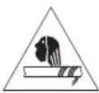
Operating instructions
Read the operating manual carefully before using the device.
Risk of clothing or body parts being caught and jammed in the machine
When servicing, repairing, maintaining or cleaning the machine there is a risk that spinning parts may result in clothing or body parts being caught in the machine causing injury. The safety instructions described in the operating manual must be observed in these cases.
Charger and battery
Only use the charger approved by the manufacturer and delivered with the sweeping machine.
2.7 Personal Safety Equipment
Personal safety equipment must be worn when working to minimise health hazards. For that reason:
- Before starting all work put on each item of specified safety equipment properly and wear it during work.

Sturdy footwear
Wear sturdy footwear with well-gripping, non-slip soles.

Protective gloves
Wear protective gloves.

Dust protection mask
Wear a dust protection mask.
3. Technical data
Basic information on the sweeping machine starmix 697
EN
| Technical data 697 | |
| Sweeping width in millimetres [mm] | 970 |
| Sweeping capacity in square metres per hour [ m^2/h ] | 4100 |
| Capacity of the sweeping container in litres [l] | 40 |
| Weight kilogrammes [kg] 22 | |
| Approx operating time* in minutes when fully charged. | 90 |
| Maximum operating temperature | 10 °C to 40 °C |
| Noise and vibration information(measured according to EN 60335-2-72) | measured according to EN 60745-2-6 |
| 697 | |
| Sound pressure level L_p (EN 60335-2-72)* 64 dB (A) | |
| Sound power level L_w (EN 60335-2-72)* 80 dB (A) | |
| Uncertainty for given sound level (2006/42/EG) 2.5 dB (A) |
*Calculated at the highest notational rotation speed in an ambient temperature of 20 °C / depending on floor surface.
| Vibration information (measured according to EN 60335-2-72) 697 | |
| Left handle, ah | < 2.5 m/s ^2 |
| Right handle, ah | |
| Uncertainty (K) (RL 2006/42/EG) 2.0 m/s ^2 | |
| Battery 697 | |
| Voltage [V] 12 | |
| Power [Ah] 14 | |
| Weightkilogrammes [kg] | 4,0 |
| Maximum range of temperature | |
| Operation from -10 | °C to +50 °C |
| Charging from 0 | °C to +40 °C |
| Storage from -10 | °C to +40 °C |
| Charger | 697 |
| Input voltage | 230 VAC/50 Hz |
| Output voltage [V] | 12 |
| Charge cut-off voltage [V] | 13.8 |
| Charging current [mA] | 3,000 |
| Weight in grams [g] | 350 |
| Maximum range of temperature | |
| Operation | from 0 °C to +25 °C |
| Storage | from -25 °C to +70 °C |
4. Construction and Function
EN
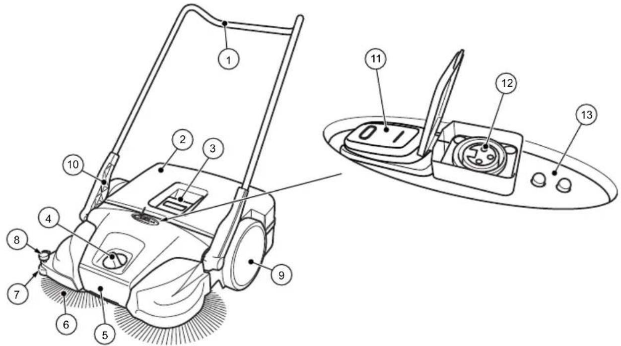
Fig. 1: Component overview 1
| Item no. | Component |
| 1 Push bar | |
| 2 Sweeping container | |
| 3 Container handle | |
| 4 Plate brooms – height adjustment | |
| 5 Carrying handle | |
| 6 Plate brooms | |
| 7 Lateral guide roller | |
| 8 Downholder | |
| 9 Impeller | |
| 10 Handle fitting | |
| 11 On/off switch | |
| 12 Charging socket | |
| 13 LED display |
The battery-operated machine is started by switching the on/off switch (11) to the on position and pushing the machine forward with the push bar (1). This causes both plate brooms (6) to convey the sweepings in the direction of the sweeping container (2) with the aid of the sweeper lip (16).
The fine dirt sweeping roll (14) conveys the rest of the sweepings into the sweeping container (2). Power is provided by the battery (24) installed in the machine, which must be sufficiently charged for optimal performance.
» Information on the charging of the battery can be found in Chapter "6.3 Charging battery" of this operating manual.
During battery operation the current operating status of the sweeping machine is shown on the LED display (13).
» Information on battery operation and the LED display can be found in Chapter "7.4 Battery operation and LED display" of this operating manual.
When the battery charge is low, the machine may also be operated temporarily without electric power.
» Information on manual operation can be found in Chapter "7.6 Manual operation" of this operating manual.
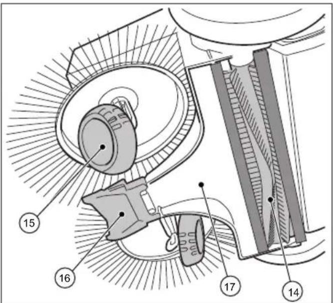
Fig. 2: Component overview 2

Fig. 4: Component overview 4
| Item no. Component |
| 14 Fine sweeping roll |
| 15 Helical gear |
| 16 Sweeper lip |
| 17 Sweeping plate |
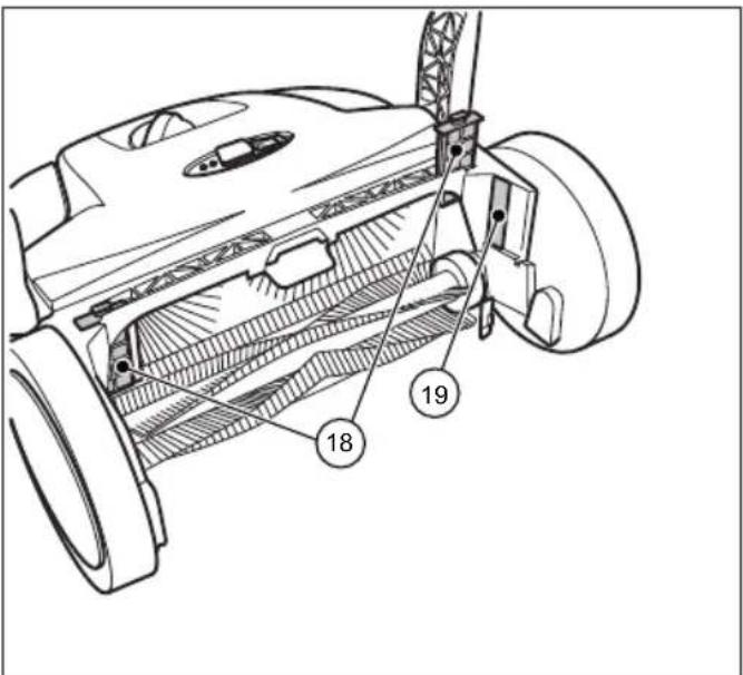
Fig. 3: Component overview 3
| Item no. Component |
| 20 Clutch housing |
| 21 Toothed sleeve |
| 22 Helical gear toothing |
| 23 Drive protection |
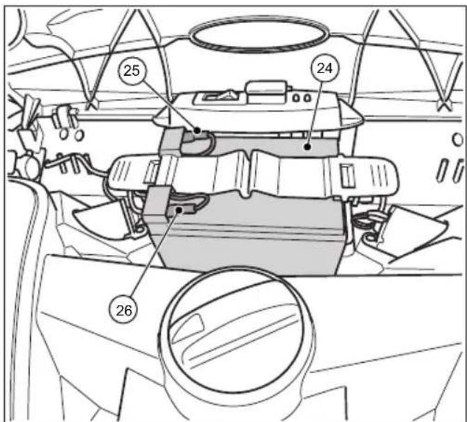
Fig. 5: Component overview 5
| Item no. Component |
| 18 Dust filter |
| 19 Type plate |
| Item no. Component | |
| 24 Battery | |
| 25 Battery connection lead (red +) | |
| 26 Battery connection lead (blue -) | |
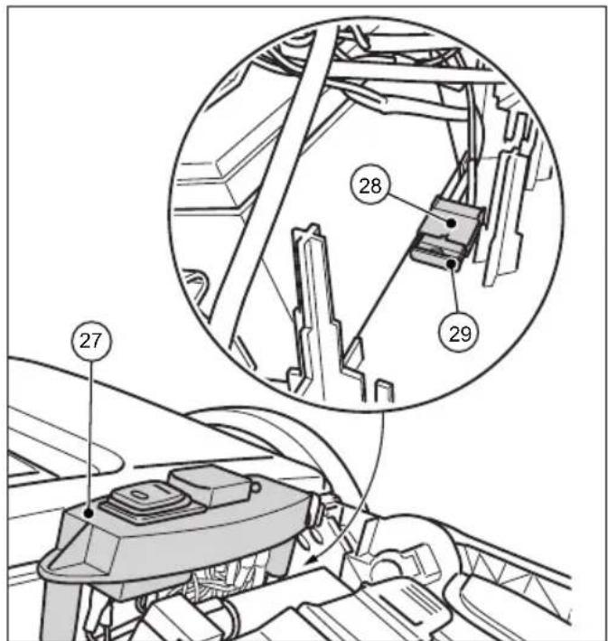
Fig. 6: Component overview 6
| Item no. Component |
| 27 Switch plate |
| 28 Fuse holder |
| 29 Fuse F1 |
» The picture shows the components when the cover is open or removed.
5. Transport/transporting
5.1 Delivery
NOTE
Visible damage on the outer packing must be immediately confirmed on delivery by the parcel service driver. If transport damage is only noticed during unpacking, the parcel service must be notified in writing within 24 hours after delivery so that it can be liable for the damage
5.2 Scope of supply
- Device
- Push bar
- Two handle fi ttings (pre-mounted)
- Charger with mains plug.
- Operating instructions
5.3 Handling Packaging Materials
• Always dispose of packing in an environmentally responsible manner.
- Observe the local and regional legal provisions in force.
5.4 Storage of sweeping machine
NOTE
Damage can be caused by improper storage of the machine, e.g. in a damp environment, with the battery lead attached, or with an insufficiently charged battery. Informatic regarding the storage and safekeeping of the machine can be found in Chapter "10. Decommissioning for Storage/Safekeeping".
» In order to save space, the push bar can be detached from the machine. Information on the removal of the push bar can be found in Chapter "10.1 Disassemble push bar" of this operating manual.
5.5 Carrying the device

CAUTION
Risk of injury through tipping over of the push bar!
Tipping over of the push bar may lead to slight injuries, such as jamming of the finger o bruising in users or other persons.
- When carrying the device, hold it so that the push bar cannot tip over.

Fig. 7: Carrying the device
- Swing the push bar (1) fl at towards the front.
- Grasp the device on the carrying handle (2).
- Carry the device in such a manner that the plate brooms face away from the body.
5.6 Transporting the device in a vehicle

CAUTION
Risk of injury through improper transport of the sweeping machine!
Wandering, skidding or tipping of the device can result in injury to the driver or other persons
- Secure the device with a strap to prevent it from slipping and moving around.
- Place the device in a suitable location in the vehicle.
- Secure the device with a strap.
» In order to save space when transporting the device in a vehicle, the push bar can be removed. Information on the removal of
the push bar can be found in Chapter "10.1 Disassemble push bar" of this operating manual.
NOTE
- Improper transport can result in damage to the sweeping machine.
- In order to protect the battery, do not leave the machine in a hot vehicle.
- Ensure that the device is not switched on by accident during transport. If necessary, disconnect the blue battery lead. Information on the disconnection of the battery can be found in Chapter "10.2 Disconnect battery leads" of this operating manual
6. Commissioning
6.1 Install push bar

CAUTION
Risk of injury through tipping over of the push bar!
Tipping over of the push bar may lead to slight injuries, such as jamming of the finger o bruising in users or other persons
- When carrying the device, hold it so that the push bar cannot tip over
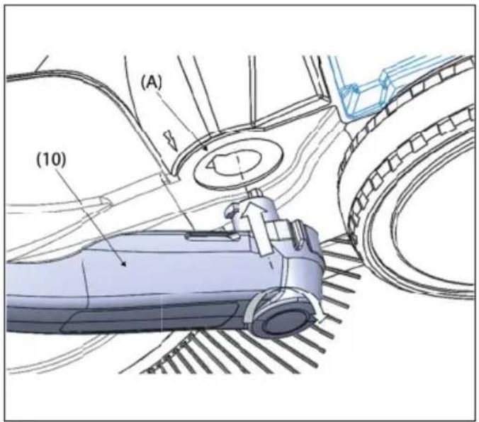
Two handle fi ttings (10) and the sliding bracket (1) are included as individual parts in the delivery.
- press the locking spring (B) on the side of the of the push bar (1) inwards.
- push the handle fi tting (10) onto the push push bar until it engages.
» Make sure that the side hole on the hole on the side of the handle fi tting aligns with the spring in the push bar.
- proceed in the same way with the second side of the push bar in the same way
The sliding bracket (1) can be adjusted to the height of the user at two levels (I) and (II).
» (I): Lower level
» (II): Upper level (favoured position)
Fig. 8: Fitting the handle fittings
- The sliding bracket (1) can be adjusted to the Position yourself between the push bar (1) in front of the appliance.
- Place one of the two handle fittings with the latching lug on the handle fitting (10) to the groove provided on the frame (A) so that it so that it can snap into place
- Move the handle fi tting (10) on the other side other side into this position as well.
- Now the handle fittings can be snapped into the holders in the appliance (A) with a little pressure and the push handle (1) can be brought into the required position for pushing the appliance.
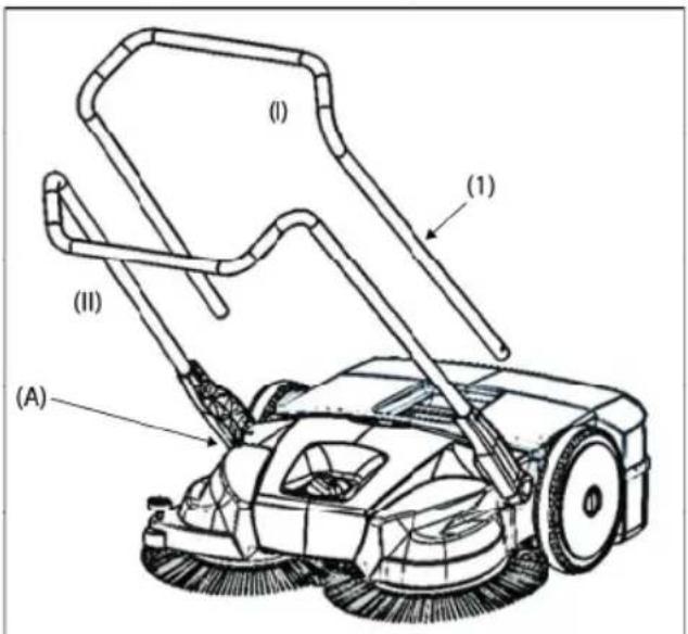
- Push the push bar (2) into both handle fi ttings simultaneously.
» To do so, the push bar must be pulled apart about 10 cm before insertion in the handle fi ttings. - Push the push bar (2) into the handle fittings until the locking springs lock in.
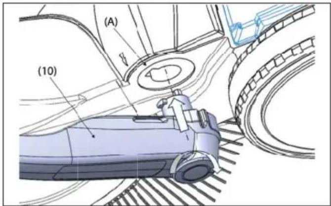
6.2 Connect battery leads
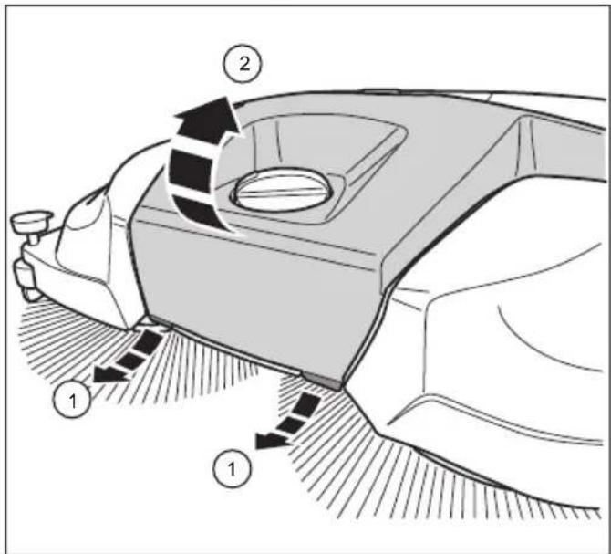
Fig. 9: Open the cover
CAUTION
Risk of injury from unintentional starting of the sweeping machine.
When the battery lead is connected there is a danger of items being pulled into the machine due to the unintentional starting of the sweeping machine.
- Before the battery is connected ensure that the position of the on/off switch is in (1) position
» Upon delivery and for storage times of 2 months or more, the blue battery lead should be removed from the insertion fl ap to prevent the battery losing its charge.
1. Pull the two fl aps (1) on the front underside of the cover (2) a short distance forwards.
2. Lift the cover (2)
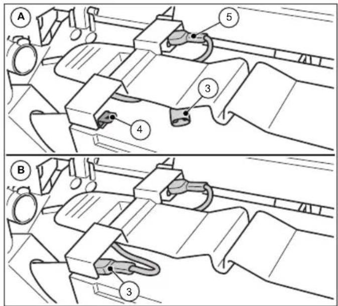
Fig. 10: Connect battery leads
- Plug the blue battery lead (3) well into the insertion flap (4) of the battery.
» (A): Battery lead not connected
» (B): Battery lead connected
» The red battery lead (5) is connected upon delivery.
NOTE
Also ensure that the red battery lead (5) is completely and correctly connected. An incorrect connection to the battery can cause damage to the device and result in the guarantee being deemed to be void.
- Close the cover (2) and lock it over the fl aps (1).
6.3 Chargingbattery
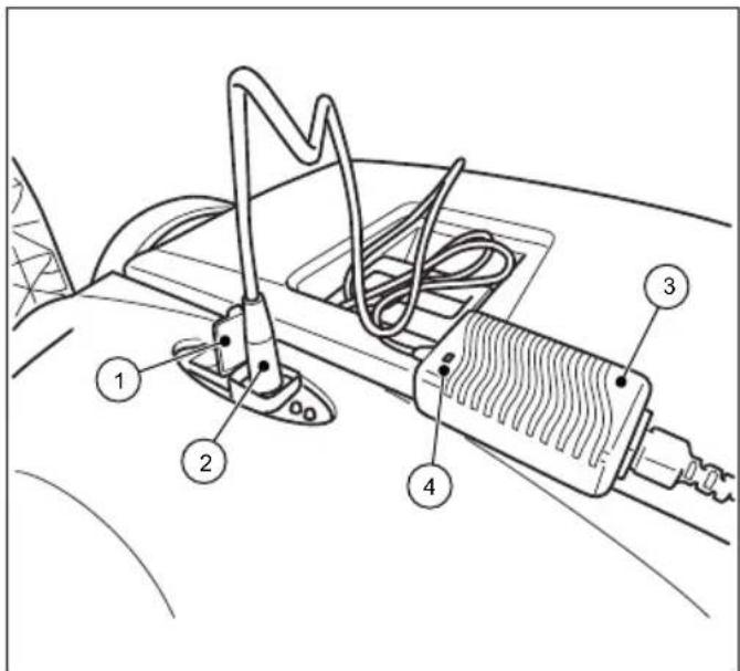
Fig. 11: Connecting the charger
» It is recommended to charge the battery fully before being operated for the first time.
» The charger (3) has fully electronic voltage and current limitation. This enables a connected battery to be at optimal charge at all times. The battery is thus prevented from overcharging.
» The battery leads must be correctly connected in order to charge the batteries. Information on the connection of the battery can be found in Chapter "6.2 Connect battery leads" of this operating manual.
NOTE
- The sweeping machine must not be switched on during charging. This may cause damage to the machine's electrical components.
-
Before charging, check the charger plug and the connection socket on the sweeping machine for foreign bodies such as objects which may conduct electricity. Damage to the device from short-circuits and cable fi re
-
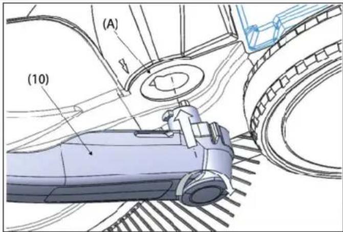
Open the protective cap (1) over the charging socket on the sweeping machine.
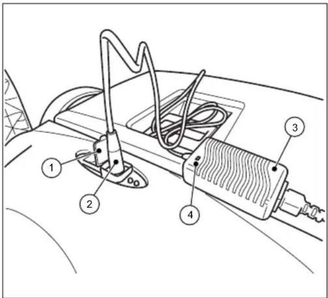
Fig. 12: Connecting the charger
- Connect the plug (2) of the charger (3) to the charging socket of the sweeping machine.
- Connect the mains lead of the charger (3) to a 230 V power supply.
» During charging, the LED display (4) on the charger shows an orange light. When the battery has been completely charged, the LED display (4) on the charger changes to green.
» Charging time depends mainly on the charge of the battery before charging. If the battery has not been charged for some time, the charge will have dropped and the charge time will be longer. A full charge can take up to 7 hours. Please also note the information on the outer packing or on the sticker fixed to the sweeping machine.
NOTE
In order to achieve optimal life and keep the aging process to a minimum, the battery should be charged for at least 10 hours every 2 months. A fully charged battery reduces the danger of deep discharge and irreparable damage to the battery cells. The battery can also be recharged after operation times of approx. 15 mins.
7. Operation

WARNING
Risk of cutting due to broken glass, metal or other sharp edged materials!
When emptying the sweeping container, cutting injuries may occur due to broken glass, metal or other sharp edged materials.
- Wear the prescribed personal protective equipment!

CAUTION
Health impairments caused by dust resulting from sweeping
The inhalation of dusts can endanger the health.
- Wear the prescribed personal protective equipment!
7.1 Before starting work
- Check the device to make sure that it is functioning before starting work.
- Check the push bar to make sure that it is firmly fixed in the handle fittings.
- Check the sweeping container to make sure it is firmly fixed and in good condition.
- Check the plate brooms and the fi ne dust sweeping roller for bits of wood, rolled up threads and cords, and materials with long strands. Remove these if necessary.
- Check the plate brooms and the fi ne dust sweeping roller for jammed items or contamination.
- Check the handle for contamination and clean if necessary.
- Check whether the on/off switch can be easily moved to the 0 position at any time.
- Check the charging socket on the sweeping machine for foreign bodies.
NOTE
There must be no electrically conductive objects on or in the charging socket. Damage to the device from short-circuits and cable fi re. Always keep the protective cap over the charging socket closed.
7.2 Height adjustment of the plate brooms
The height of the brooms is adjusted with a dial in the middle of the front part. The height adjustment sets the plate brooms to the surface to be swept. The levels are based on empirical values and must therefore be regarded as reference values. As a result, during sweeping, adaptations of the levels may need to be made depending on the surface.
• Level 1-2: for all level, hard surfaces
(e.g. asphalt, concrete, slabs...)
- Level 3-4: for damp leaves, sand, and uneven surfaces (e.g. washed concrete slabs)
• Level 5-7: for heavy soiling and severely uneven surfaces
NOTE
Do not press the plate brooms too firmly or the ground. This leads to increased wear and tear and a reduction of the charge run time. It also increases push resistance and can have a negative effect on the cleaning result
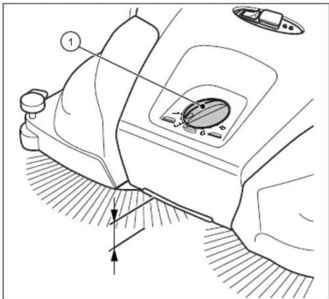
Fig. 13: Height adjustment of the plate brooms
- Set the required level:
- Turn the dial (1) to the left to lower the level.
- Turn the dial (1) to the right to increase the level.
» Lift the machine slightly by the handle. This will make it easier to adjust the height.
7.3 Set hold-down device
With the hold-down device, the right plate broom is adjusted to the edge regions to be swept, for example on walls or curbs.
NOTE
An unsuitable setting of the hold-down device at lower edges can lead to excessive wear. The hold-down device must not scratch on the ground.
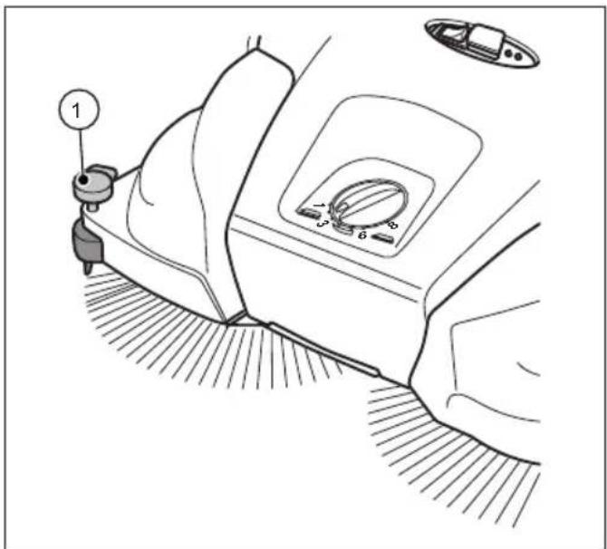
Fig. 14: Hold-down device setting
Sweeping out edges and corners
- Press down the handle (1) of the hold-down device.
Operation on surfaces
- Pull up the handle of the hold-down (1) device.
7.4 Battery operation and LED display
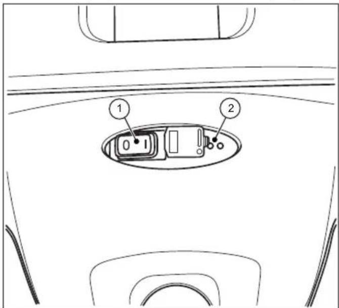
Fig. 15: Use and display
The LED display (2) communicates the operating state of the battery-operated sweeping machine.
- Place the sweeping machine on the surface to be swept.

CAUTION
Do not operate the on/off switch with you foot.
This may cause injury by causing you to fall or stumble when the plate brooms on the sweeping machine begin to move
• Only switch the machine on by hand
- Switch on the sweeping machine by switching the on/off switch (1) to position I.
The plate brooms and fi ne sweeping rolls begin to rotate. The LED display (2) will show green during battery operation provided there is suffi cient charge.
Operation
starmix 697
starmix
EN
- Use both hands to push the device with the push bar.
- Push the device forward at normal walking speed.
- Switch off the sweeping machine by moving the on/off switch (1) to position 0.
- Empty the sweeping container as needed. See Section "Empty sweeping container" in Chapter 7.7 of this operating manual.
» Empty the sweeping container at regular intervals to achieve a satisfactory sweeping result.
NOTE
- If the plate brooms are revolving more slowly or if the red light on the LED display (2) shows during operation, this means that the battery charge is low. Switch off the machine and charge the battery.
- When the battery charge is too low, the machine will be switched off automatically by the electronic system installed. The red LED display light (2) will fl ash red. Switch off the machine and charge the battery. The guarantee is void if the battery is allowed to deep discharge.
- Clean the sweeping machine and dust filter after operation. See Section "Clean the device" in Chapter9.5 of this operating manual.
- Fully charge the battery again as needed. See Section "Charging battery" in Chapter 6.3 of this operating manual.
7.5 Overloadprotection
In order to avoid damage from overload, the motors are fitted with overload protection. If the electronics of the sweeping machine switch themselves off after a short time, this means that the motors are being overloaded. Check the fine sweeping roll and the plate brooms are moving freely and remove any blockages, such as stones, rolls of thread and similar items.
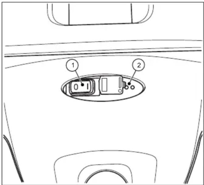
Fig. 16: Use and display
- Set the on/off switch (1) on the electronics of the machine to the 0 position after the overload protection has been triggered.

CAUTION
Risk of injury from unintentional starting of the sweeping machine.
When working on the sweeping machine there is a danger of items being pulled into the machine due to the unintentional starting of the sweeping machine.
- Ensure that the device is not switched on by accident when the blockage is being dealt with. If necessary, disconnect the blue battery lead. See Section "Disconnect battery leads" in Chapter 10.2 of this operating manual.
- Locate and remove the blockage. See Section "Remove blockage" in Chapter 9.3 of this operating manual.
- If necessary, connect the blue battery connecting lead again. See Section "Connect battery leads" in Chapter 6.2 of this operating manual.
starmix
starmix 697
Operation
- Switch the sweeping machine on by switching the on/off switch to the I position.
- Check whether the device is working again as usual.
7.6 Manualoperation
When the battery is low, the sweeping machine can be used temporarily without a power supply. The sweeping mechanism is activated by pushing the machine forward.
- Use both hands to push the device with the push bar.
- Push the device forward at normal walking speed.
- Empty the sweeping container as needed. See Section "Empty sweeping container" in Chapter 7.7 of this operating manual.
- Fully charge the battery again as needed. See Section "Charging battery" in Chapter 6.3 of this operating manual.
» Only use manual operation temporarily. Results are better under battery operation and use a very small amount of power.
7.7 Empty sweeping container

WARNING
Risk of cutting due to broken glass, metal or other sharp edged materials!
When emptying the sweeping container, cutting injuries may occur due to broken glass, metal or other sharp edged materials.
- Wear the prescribed personal protective equipment!

CAUTION
Risk to health from dust from sweeping container!
There is a risk to health from dust collected when the sweeping container is emptied.
- Wear the prescribed personal protective equipment!
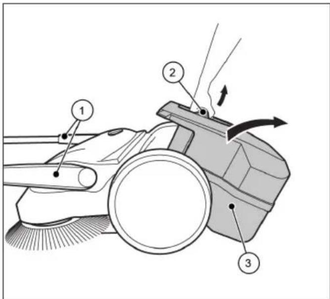
Fig. 17: Empty the sweeping container
• Empty the sweeping container after each use.
• Empty the sweeping container at regular intervals to achieve a proper sweeping result.
1. Bring the push bar (1) to the forward position.
2. Pull the sweeping container (3) upwards by the container handle (2).
3. Empty the sweeping container (3) completely.
» Make sure that the enclosure sides are free of dirt.
4. Insert the empty sweeping container (3) on the device.
5. Press the container handle (2) back into the starting position. To do this, simultaneously press with force in the direction of the sweeper so that the hook of the container handle can easily hook into the locking point on the sweeper.
» The sweeping container (3) must audibly lock into position.
6. Bring the push bar (1) back into the operating position.
8. Troubleshooting

WARNING
Risk of cutting due to broken glass, metal or other sharp edged materials!
When emptying the sweeping container, cutting injuries may occur due to broken glass, metal or other sharp edged materials.
- Wear the prescribed personal protective equipment!

CAUTION
Health impairments caused by dust resulting from sweeping!
The inhalation of dusts can endanger the health
- Wear the prescribed personal protective equipment!

CAUTION
Risk of injury through tipping over of the push bar!
Tipping over of the push bar may lead to slight injuries, such as jamming of the finger o bruising in users or other persons.
- When carrying the device, hold it so that the push bar cannot tip over.

CAUTION
Risk of injury from unintentional starting of the sweeping machine.
When working on the sweeping machine there is a danger of items being pulled into the machine due to the unintentional starting of the sweeping machine.
- Ensure that the device is not switched on by accident while the fault is being dealt with. If necessary, disconnect the blue battery lead. See Section "Disconnect battery leads" in Chapter 10.2 of this operating manual.
Faults may occur even if the prescribed maintenance work and checks of the device before use are complied with. Possible faults are listed in the tables 1 and 2 below, with specification of the cause and remedy.
8.1 Fault table Part 1
| Fault Cause Remedy | ||
| Device is running with difficulty or roughly | Device is contaminated | Clean sweeping machine. See Chapter 9.5 Section “Clean the device” |
| Broom blocked | Remove blockage, see Chapter 9.3 Section “Remove blockage” | |
| Contaminated broom drives | Clean broom drives. See Chapter 9.5 Section “Clean the device” | |
| Height adjustment set too low | Set height adjustment, See Chapter 7.2 in Section “Height adjustment of the plate brooms” | |
| Plate broom pressure too high | ||
| Battery charge too low. LED display on the sweeping machine shows red light | Charge battery. See Chapter 6.3 Section “Charging battery” | |
| Plate brooms do not rotate | Contact Service | |
| Fine sweeping roll does not rotate | ||
| The device is switched off | Plate broom pressure too high | Set height adjustment. See Chapter 7.2 in Section “Height adjustment of the plate brooms” |
| Broom blocked | Clean sweeping machine. See Chapter 9.5 Section “Clean the device” | |
| Overload protection active | Remove blockage, see Chapter 7.5 Section “Overload protection” | |
| Battery charge too low. LED display on the sweeping machine shows red light. Device switched off electronically | Charge battery. See Chapter 6.3 Section “Charging battery” | |
| F1 fuse is defective | Check F1 fuse and exchange. See Chapter 8.4 Section “Take out the F1 fuse and check” | |
| Device can’t be switched on | F1 fuse is defective | Check F1 fuse and exchange. See Chapter 8.4 Section “Take out the F1 fuse and check” |
| Disconnected battery lead | Connect battery lead. See Chapter 6.2 Section “Connect battery leads” | |
| Deep discharge battery Contact Service | ||
| Bristles are bent Improper storage | Align the bristles, see Chapter 9.4 Section “Align bristles” |
8.2 Fault table Part 2
| Fault Cause Remedy | ||
| Sweeping result is insufficient | Sweeping lip is missing, loose or worn Replace sweeping lip | |
| Plate broom pressure too high | Set height adjustment. See Chapter 7.2 in Section “Height adjustment of the plate brooms” | |
| Heavy wear and tear of plate brooms | ||
| Exchange plate brooms | ||
| Sweeping container is full | Empty the sweeping container. See Chapter 7.7 Section “Empty sweeping container” | |
| Inappropriate use of sweeping machine according to information in Chapter 2.2 Section “Inappropriate use” | Use suitable cleaning device or cleaning agent. | |
8.3 Trouble-shooting procedure

CAUTION
Risk of injury from unintentional starting of the sweeping machine.
After correcting fault on the sweeping machine there is a danger of items being pulled into the machine due to the unintentional starting of the sweeping machine.
- Before the battery is connected ensure that the position of the on/off switch is in (1) position.
- Set on/off switch on the device to position 0.
- If necessary, disconnect the blue battery lead.
- Correct the fault as described in the fault table.
- If necessary, reconnect the blue battery connecting lead.
- Switch the sweeping machine on by switching the on/off switch to the I position. Check whether the device is working again as usual.
8.4 Take out the F1 fuse and check
In order to protect the electrical components, the sweeping machine is fitted with a 15 amp safety fuse. In order to check and replace the F1 fuse proceed as follows:

CAUTION
Danger of injury or accident due to incorrect fuse strength.
Use of the incorrect fuse strength can lead to overload of the electrical components, the emission of smoke, or fire, whether the machine is switched off, being charged or in operation.
- Replace the fuse only with a new 15 amp fuse approved by the manufacturer.

CAUTION
Risk of injury from unintentional starting of the sweeping machine.
When working on the sweeping machine there is a danger of items being pulled into the machine due to the unintentional starting of the sweeping machine.
- Ensure that the device is not switched on by accident while the fuse is being taken out and checked. If necessary, disconnect the blue battery connecting lead.
NOTE
Serious damage to the device can be caused by use of a fuse with a higher or lower strength.
In order to avoid damage, replace a blown fuse only with a 15 amp fuse approved by the manufacturer. Only replace the fuse when the cause of the fault has been dealt with
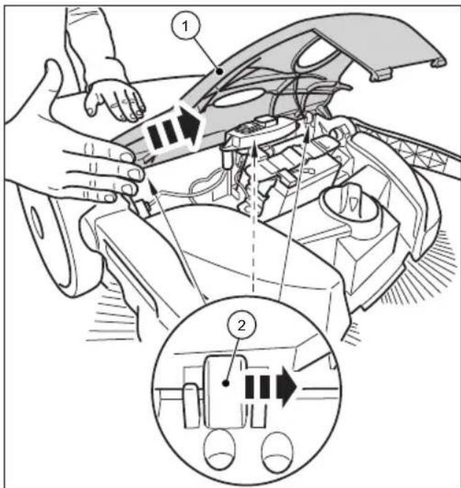
Fig. 18: Remove cover
-
Set on/off switch on the device to position 0.
-
Move the push bar to the forward position. See Section "Empty sweeping container" in Chapter 7.7 of this operating manual.
- Disconnect the blue battery connection lead from battery. See Section "Disconnect battery leads" in Chapter 10.2 of this operating manual.
- Remove the cover (1) from the hinges (2) carefully by tapping gently with the palm of one's hand against the edge of the cover in the direction of the arrow.
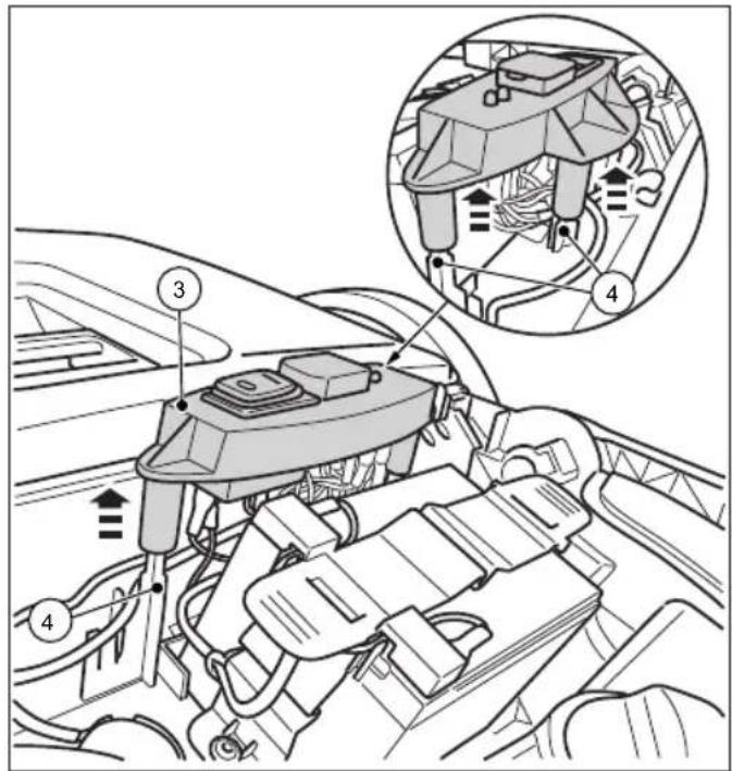
Fig. 19: Remove the switch plate
- Pull the switch plate (3) carefully upwards from the pilot pins (4).
- Place the switch plate (3) with the connected leads to one side.
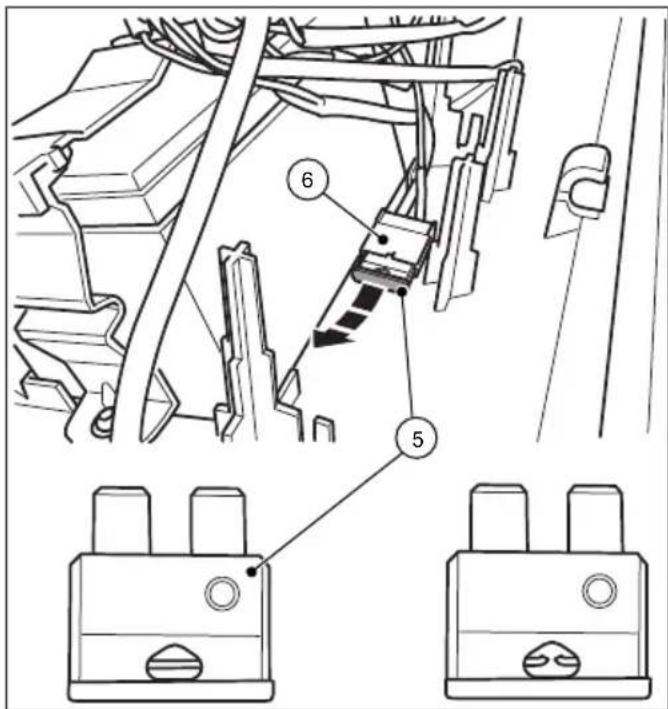
Fig. 20: Fuse F1
- Remove the F1 fuse (5) from the fuse holder (6).
- Check the fuse and, if necessary, replace.
» The picture to the right shows a blown fuse.
» Use only 15 amp fuses.
» Reassembly is carried out in reverse order.
The following must be taken into account:
- Place the cover on top and then snap it into place by carefully pressing it in the hinges.
- Plug the blue battery lead well into the insertion flap of the battery.
- Switch the sweeping machine on by switching the on/off switch to the I position.
- Check whether the device is working again as usual.
NOTE
If the fuse blows immediately after the sweeping machine has been switched on again, contact service department.
9. Maintenance and cleaning

WARNING
Risk of cutting due to broken glass, metal or other sharp edged materials!
When emptying the sweeping container, cutting injuries may occur due to broken glass, metal or other sharp edged materials.
- Wear the prescribed personal protective equipment!

CAUTION
Health impairments caused by dust resulting from sweeping!
The inhalation of dusts can endanger the health
- Wear the prescribed personal protective equipment!

CAUTION
Risk of injury through tipping over of the push bar
Tipping over of the push bar may lead to slight injuries, such as jamming of the finger or bruising in users or other persons.
- When carrying the device, hold it so that the push bar cannot tip over.

CAUTION
Hazard due to cleaning materials!
The agents can contain harmful ingredients and can thereby cause irritation of the respiratory tract and the skin
- Observe the manufacturer's safety data sheet.
- Avoid spillage and the formation of fog.
- Do not eat, drink or smoke while working
- Avoid contact with skin and eyes.

CAUTION
Risk of injury from unintentional starting of the sweeping machine.
When carrying out maintenance and cleaning the sweeping machine there is a danger of items being pulled into the machine due to the unintentional starting of the sweeping machine
- The device should be switched off and disconnected from mains supply during all such work.
- Never do any work on the machine while the engine is running.
- The on/off switch must be in the 0 position
- Ensure that the device is not switched on by accident while maintenance and cleaning work is being carried out. If necessary, disconnect the blue battery lead. See Section “Disconnect battery leads” in Chapter 10.2 of this operating manual.
NOTE
Improper maintenance can lead to damage or a shortening of the life of the sweeping machine.
In the following sections the maintenance and cleaning work required for optimal and fault-free operation is described.
The conduct of the specified work depends in some cases on time and/or charge. For the maintenance interval information shown both in deadlines and service hours, the one that occurs first applies.
In case of questions on the maintenance work and intervals contact the manufacturer.
9.1 Maintenance plan
| Maintenance interval | Maintenance work |
| Before starting work | Check the device to make sure that it is functioning before starting work. If necessary, contact the Service |
| Check the push bar to make sure that it is firmly fixed in the handle fittings. | |
| Check the sweeping container to make sure it is firmly fixed and in good condition. | |
| Check the plate brooms and the fine dust sweeping roller for rolled up threads and cords. Remove these if necessary. | |
| Check the plate brooms and the fine dust sweeping roller for jammed items or contamination | |
| Check the handle for contamination and clean if necessary. | |
| Check that the height is adjusted correctly | |
| Check the sweeping pressure setting. Adapt the sweeping pressure to the surface to be swept, if necessary | |
| Check whether the on/off switch can be easily moved to the 0 position at any time | |
| Check the charging socket on the sweeping machine for foreign bodies | |
| Check the charge on the battery is sufficient for the sweeping work planned. Charge battery if necessary. | |
| After finishing work | Empty the sweeping container |
| Clean the device | |
| Clean dust filter | |
| Charge battery | |
| 8 Bh Clean broom drives | |
| 2 months Charge battery | |
9.2 Clean dust filter
- Remove the sweeping container from the sweeping machine. See Section "Empty sweeping container" in Chapter 7.7 of this operating manual.
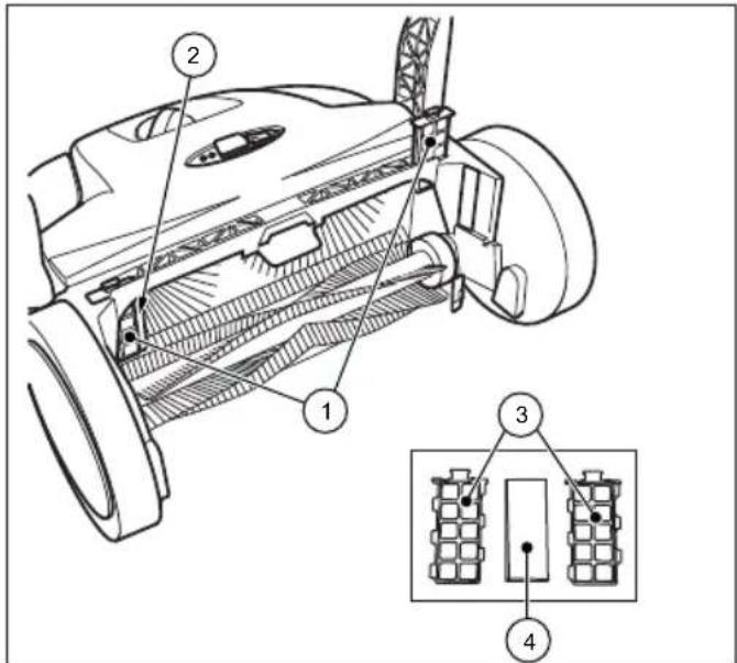
Fig. 21: Dust filter removal
- Pull the dust filter (1) up from the guides (2).
- Open the plastic housing (3) of the dust filter and remove the foam insert (4).
- Pound out the foam insert (4) and clean it with water.
- Place the dry foam insert back into the plastic housing.
- Slide the dust filter back into the guides.
- Insert the sweeping container into the sweeping machine.
9.3 Remove blockage
- Remove wound-up material (e.g. cords, threads, long-threaded fibres.) from the brooms and axles.
- Remove jammed material (e.g. stones, twigs, leaves etc.).
9.4 Alignbristles

WARNING
Fire hazard due to improper handling of a fan or the use of an unsuitable fan!
When aligning the bristles, there is a risk of fire if they are heated to too high temperatures
- Do not use open flames or furnace to hea the bristles!
- Do not use a hot air blower. If the air is too hot, the bristles may melt.
Bent bristles can be straightened out again with heating by means of a warm air fan (e.g. hairdryer).
- Point the switched-on warm air fan towards the bent bristles.
» If the heating is sufficient, the bristles will straighten out again by themselves.
9.5 Clean the device
- Do not use a degreasing agent.
- Do not use any aggressive cleaning agents.
- Do not clean the device with a high-pressure cleaner or under running water. The device may not be immersed in water or cleaned with water.
- Protect the bearings against moisture.
-
Do not clean the plate brooms and the fine dirt sweeping roll with compressed air.
» The strong air jet can damage the bristles. -
Clean the plate brooms, the fi ne dirt sweeping roll and the drives with a wet cloth.
-
Clean all plastic parts with a damp cloth.
» Keep the battery clean as a dirty battery can lead to battery leakage via the terminals over time.
- Clean the dust fi iter.
10. Decommissioning / Storage/ Safekeeping
10.1 Disassemble push bar

CAUTION
Risk of injury through tipping over of the push bar!
Tipping over of the push bar may lead to slight injuries, such as jamming of the finger o bruising in users or other persons
- When carrying the device, hold it so that the push bar cannot tip over
» In order to save space, the push bar can be detached from the machine.
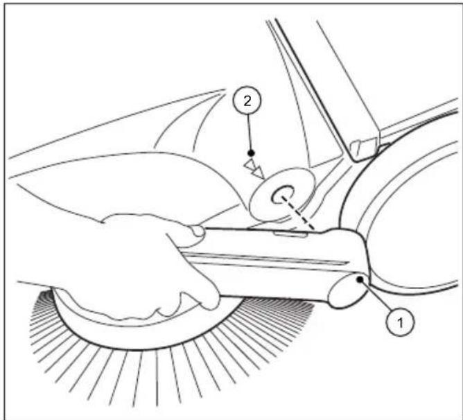
Fig. 22: Push bar disassembly
- Align the respective arrows (2) on the housing with the bar of the handle fittings (1).
- Position yourself between the push bar in front of the device.
- Grip both handle fittings (1) with your hands and carefully push them out.
- At the same time pull out the handle fittings from both receptacles of the device.
10.2 Disconnect battery leads
When the battery is stored for 2 months or more without being recharged the blue battery connection lead should be disconnected in order to prevent the battery from deep discharging.
EN
In addition, if necessary, the battery should be disconnected during fault correction and removal of blockages. Protection from accidental starting of sweeping machine.
If the battery is to be stored for 6 months or more the battery must be fully charged in order to retain the performance of the battery. Information on the charging of the battery can be found in Chapter "6.3 Charging battery" of this operating manual.
» Keep the battery clean as a dirty battery can lead to battery leakage via the terminals over time.
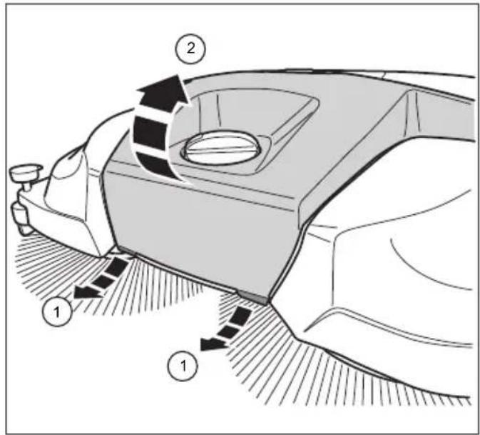
Fig. 23: Open the cover
- Pull the two flaps (1) on the front underside of the cover (2) a short distance forwards.
- Lift the cover (2)
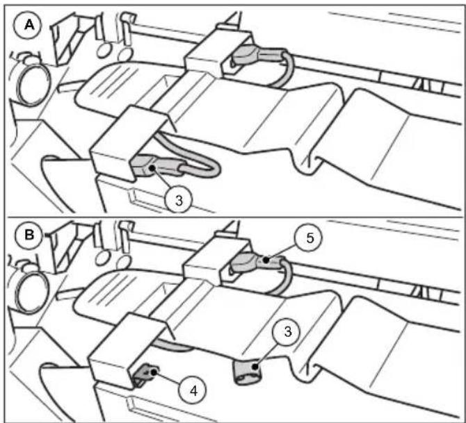
Fig. 24: Disconnect battery leads
- Disconnect the blue battery lead (3) from the insertion flap (4) of the battery.
» Ensure that external influences such as the movement of the device cannot cause the blue battery lead (3) to contact the insertion flap (4) (see Illustration 24 picture B).
» The red battery lead (5) remains connected.
- Close the cover (2) and lock it over the flaps (1).
10.3 Storage/Safekeeping
NOTE
Improper storage, e.g. storage of the device in a humid environment, can lead to damage to the sweeper
» Note the information contained in Chapter "10.2 Disconnect battery leads" of these operating instructions.
- Store the sweeping machine only in cleaned condition and with an emptied sweeping container.
» Information on emptying the sweeping container can be found in Section "7.7 Empty sweeping container" and on cleaning in Section "9.5 Clean the device" of this operating manual.
natural_image
Technical line drawing of a mechanical device with gears and shafts (no text or symbols)Fig. 25: Storage position
- Place the device in such a way that the bristles cannot be kinked or bent.
- Secure the device, including push bars, against tipping over, slipping and thus against damage.
- Do not store the device outdoors or in damp environments.
10.4 Disposal
- Dispose of the sweeping machine, the charger and the battery in an environmentally friendly manner in accordance with the applicable regional regulations.
- Dispose of the device and the battery separately.
chemical
Chemical structure and recycling symbol of lead (Pb) showing a waste bin and a recycling symbol11. REACH
REACH is the European Chemical Directive for the Registration, Evaluation, Authorisation and Restriction of Chemical substances.
Information regarding compliance with REACH directive (EU) Nr. 1907/2006 can be found atwww.starmix.de
12. EU Declaration of Conformity
EU Declaration of Conformity in accordance with Machine Directive 2006/42/EC Annex II 1.A
Manufacturer:
Electrostar GmbH
Hans-Zinser-Str. 1-3
73061 Ebersbach/Fils
Germany
Authorised for the preparation of technical documents:
Electrostar GmbH
Hans-Zinser-Str. 1-3
73061 Ebersbach/Fils
Germany
Product:
Hand controlled, battery-operated sweeping machine starmix 697
We hereby declare that the above-mentioned product complies with the provisions of machine directive 2006/42/EU The above-mentioned product complies with the demands of the relevant directives:
• EMC Directive 2014/30/EC
• RoHS 2011/65/EC
The following harmonised standards were applied:
• EN ISO 12100:2010, Safety of machinery, general principles for design, risk assessment and risk reduction
- EN 60335-1:2012, Safety of electric devices for use at home and similar purposes - Part 1: General Requirements
- EN 60335-2-72:2014, Safety of electric devices for use at home and similar purposes - Part 2-72: Special requirements for floor treatment machines, with or without drive, for commercial use
- EN 55014-1:2006+A1:2009+A2:2011, Electromagnetic compatibility - Requirements for household appliances, electrical tools and similar apparatus - Part 1: Interference Emission (CISPR 14-1:2005 + A1: 2008 + Cor. :2009 + A2:2011)
- EN 55014-2:1997+A1:2001+A2:2008, Electromagnetic compatibility - Requirements for household appliances, electrical tools and similar apparatus - Part 2: Immunity - Product family standard (IEC/CISPR 14-2:1997 + A1:2001 +A2:2008)
- EN 62233:2008-04, Measurement methods for electromagnetic fields of household appliances and similar apparatus with regard to human exposure.
• EN IEC 63000:2018-12, Technical documentation for the assessment of electrical and electronic devices with regard to the restriction of hazardous substances
Ebersbach, 21.09.2020


Carsten Gresser
Head of Assurancer
starmix
starmix 697
Table des matières
- Généralités....65
1.1 Adresse 65
1.2 Conventions....65
FR
Illustr. 20 : Fusible F1
10.3 Stockage / conservation
INDICATION
natural_image
Technical line drawing of a mechanical device with no visible text or symbolsIllustr. 25 : Position de stockage
ES
Fig. 1: Resumen de componentes 1
Fig. 2: Resumen de componentes 2
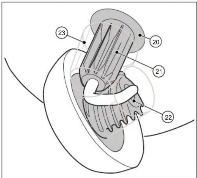
Fig. 4: Resumen de componentes 4
Fig. 3: Resumen de componentes 3
Fig. 5: Resumen de componentes 5
Fig. 6: Resumen de componentes 6
N° pos. Componente
27 Placa del interruptor
28 Portafusible
29 Fusible F1
Fig. 14: Ajuste del pisador
Fig. 19: Desmontar la placa del interruptor
Fig. 20: Fusible F1
Fig. 23: Abrir la cubierta
natural_image
Technical line drawing of a mechanical device with gears and housing (no text or symbols)chemical
Chemical symbol and its corresponding representation of a Pb-based waste bin and a recycling cycleFig. 9: Aprire la calotta
ATTENZIONE
Fig. 20: Fusibile F1
Fig. 23: Aprire la calotta
natural_image
Technical line drawing of a mechanical device with gears and shafts (no text or symbols)1.2 Conventies....155
7.5 Overbelastingsbeveiliging....170
7.6 Handmatige bediening....171
7.7 Opvangbak leegmaken 171
- Storingsoplossing....172
Afb. 9: Kap openen
VOORZICHTIG
Afb. 18: Kap demonteren
Afb. 23: Kap openen
natural_image
Technical line drawing of a mechanical device with no visible text or symbolschemical
Chemical symbol and recycling symbol for lead (Pb) showing a chemical reactor and a recycling cycle11. REACH
Fig. 1: Komponentoversigt 1
Fig. 2: Komponentoversigt 2

Fig. 4: Komponentoversigt 4
| Pos.-nr. Komponent | |
| 14 Fejevalse til fint snavs | |
| 15 Snekke | |
| 16 Fejeblad | |
| 17 Fejebakke | |
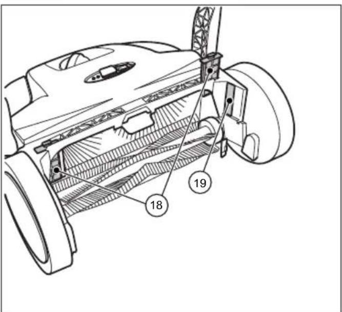
Fig. 3: Komponentoversigt 3
Fig. 7: Bær enheden
Fig. 9: Åbn hætten
! FORSIGTIG
Fig. 10: Tilslut batterikablet
Fig. 14: Nedholder indstilling
Fig. 16: Betjening og display
Fig. 17: Aff aldsbeholderen tømme
Fig. 19: Afmonter kontaktpladen
Fig. 20: Sikring F1
Fig. 22: Skubbebøjle demontering
Fig. 23: Åbn hætten
Fig. 24: Frakobl batterikablet
natural_image
Technical line drawing of a mechanical device with gears and shafts (no text or symbols)Fig. 25: Opbevaringsposition
chemical
Chemical symbol and its corresponding representation of a Pb-based waste bin and a recycling cycle11. REACH
Bild 9: Öppna huven

FÖRSIKTIGHET
Bild 19: Ta bort omkopplarplattan
Bild 20: Säkring F1
natural_image
Technical line drawing of a mechanical device with gears and shafts (no text or symbols)chemical
Chemical structure and recycling symbol of lead (Pb) showing a chemical reactor and a recycling symbol11. REACH
- Idriftssetting....255
Fig. 1: Komponentoversikt 1
Fig. 2: Komponentoversikt 2

Fig. 4: Komponentoversikt 4
| Pos.-nr. Komponent |
| 14 Feievalser til fint smuss |
| 15 Skråhjul |
| 16 Feieleppe |
| 17 Feieplate |
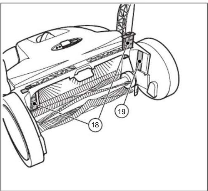
Fig. 3: Komponentoversikt 3
| Pos.-nr. Komponent |
| 20 Koblingshus |
| 21 Tannhylse |
| 22 Tennene på skråhjulet |
| 23 Drivverksbeskyttelse |
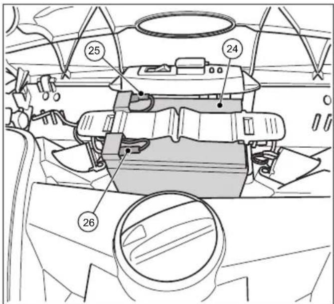
Fig. 5: Komponentoversikt 5
| Pos.-nr. Komponent |
| 18 Støvfilter |
| 19 Typeskilt |
6.2 Sett inn batteritilkoblingsledningen
Fig. 10: Sett inn batteritilkoblingsledningen
- Sett den blå batteritilkoblingsledningen (3) fullstendig på batteriets stikktapp (4)
Fig. 11: Koble til laderen
Fig. 16: Betjening og visning
Fig. 18: Demonter dekslet
Fig. 19: Demonter bryterplaten
Fig. 20: Sikring F1
Fig. 21: Å ta ut støvfiltre
Fig. 24: Å trekke ut batteritilkoblingsledningen
natural_image
Technical line drawing of a mechanical device with gears and shafts (no text or symbols)chemical
Chemical symbol and recycling symbol for lead (Pb) showing a chemical reactor and a recycling cycle11. REACH
Kuva 9: Avaa huppu
VARO
Kuva 20: Sulake F1
natural_image
Technical line drawing of a mechanical device with gears and shafts (no text or symbols)chemical
Pb (plasma boric acid) and its recycling symbolnatural_image
Technical line drawing of a mechanical device with no visible text or symbolschemical
Chemical symbol and its corresponding representation of a Pb-based waste bin and a recycling cycle11. REACH
natural_image
Technical line drawing of a mechanical device with gears and shafts (no text or symbols)chemical
Chemical symbol and its corresponding recycling symbol: a Pb-branded waste bin with crossbones and a recycling symbol with arrows.11. REACH
Obr. 15: Provoz a indikace
Obr. 16: Provoz a indikace
Obr. 18: Demontáž krytu
natural_image
Technical line drawing of a mechanical device with gears and shafts (no text or symbols)Obr. 25: Skladovací poloha
chemical
Chemical symbol and its corresponding recycling symbol: a Pb-branded waste bin with crossbones and a recycling symbol with arrows.11. REACH
natural_image
Technical line drawing of a mechanical device with no visible text or symbols

- Sprachverzeichnis
- starmix 697
- starmix
- EN Operating instructions 33
- EN
- General
- Address
- Conventions
- Numbering
- Work sequence
- Tip
- Symbols and labels
- Safety instructions
- SIGNAL WORD
- Type and source of hazard
- Risk level
- DANGER
- WARNING
- CAUTION
- Limitation of Liability
- Warranty
- Copyright
- Target group
- Safety
- Intended use
- Inappropriate use
- Responsibility of the user
- General safety instructions
- General safety instructions for battery, charging socket, and charger.
- Danger to life due to electric shock!
- Risk of death from explosion!
- Risk of injury or accident when handling the battery
- Fluid leaks from the battery may cause danger of injury or accident.
- Danger of injury and accident when handling the charger.
- NOTE
- Hazard notices on the device
- Operating instructions
- Risk of clothing or body parts being caught and jammed in the machine
- Charger and battery
- Personal Safety Equipment
- Sturdy footwear
- Protective gloves
- Dust protection mask
- Technical data
- Basic information on the sweeping machine starmix 697
- Construction and Function
- Transport/transporting
- Delivery
- Scope of supply
- Handling Packaging Materials
- Storage of sweeping machine
- Carrying the device
- Risk of injury through tipping over of the push bar!
- Transporting the device in a vehicle
- Risk of injury through improper transport of the sweeping machine!
- Commissioning
- Install push bar
- Risk of injury from unintentional starting of the sweeping machine.
- Operation
- Before starting work
- Height adjustment of the plate brooms
- Set hold-down device
- Sweeping out edges and corners
- Operation on surfaces
- Battery operation and LED display
- Do not operate the on/off switch with you foot.
- Operation
- Overloadprotection
- Manualoperation
- Empty sweeping container
- Risk of cutting due to broken glass, metal or other sharp edged materials!
- Risk to health from dust from sweeping container!
- Troubleshooting
- Trouble-shooting procedure
- Take out the F1 fuse and check
- Danger of injury or accident due to incorrect fuse strength.
- Maintenance and cleaning
- Clean dust filter
- Remove blockage
- Alignbristles
- Fire hazard due to improper handling of a fan or the use of an unsuitable fan!
- Clean the device
- Decommissioning / Storage/ Safekeeping
- Disassemble push bar
- Disconnect battery leads
- Storage/Safekeeping
- Disposal
- REACH
- EU Declaration of Conformity
- Manufacturer:
- Authorised for the preparation of technical documents:
- Product:
- The following harmonised standards were applied:
- Table des matières
- Stockage / conservation
- INDICATION
- Illustr. 25 : Position de stockage
- ATTENZIONE
- VOORZICHTIG
- ! FORSIGTIG
- FÖRSIKTIGHET
- VARO
- Obr. 25: Skladovací poloha
Brand : Starmix
Model : 697
Category : Sweeper