
ROWELD P160B - Plastic welding ROTHENBERGER - Free user manual and instructions
Find the device manual for free ROWELD P160B ROTHENBERGER in PDF.

| Product type | Thermal element butt fusion welding machine |
| Brand | Rothenberger |
| Model | ROWELD P160B |
| Category | Plastic welding |
| Pipe welding range | 40 - 160 mm diameter |
| Base machine dimensions (L x W x H) | 705 x 370 x 300 mm |
| Base machine weight | 30.2 kg (max, with reduction inserts) |
| Planing unit power supply | 230 V, 50/60 Hz, 3.5 A |
| Planing unit power | 750 W absorbed / 470 W useful |
| Heating element power supply | 230 V, 50/60 Hz, 800 W |
| Heating element diameter | 200 mm |
| Heating element temperature range | 160°C to 285°C (320°F to 545°F) |
| Hydraulic unit power supply | 230 V, 50/60 Hz, 2.5 A |
| Hydraulic unit power | 580 W absorbed / 370 W useful |
| Hydraulic pump flow rate | 2.8 l/min (50 Hz) / 2.45 l/min (60 Hz) |
| Max hydraulic pressure | 100 bar |
| Oil tank capacity | 0.7 l |
| Hydraulic oil type | HLP 46 (ref. 53649) |
| Weldable materials | PE, PP, PVDF |
| Sound pressure level (planing) | 82 dB(A) L_pA, uncertainty 3 dB |
| Maintenance | Clean heating element with ethanol >99.8%, check oil level before each use, drain oil every 6 months, replace planing blades if necessary |
| Safety | Read safety warnings, use PPE, do not expose to moisture, disconnect before maintenance |
| After-sales service | ROTHENBERGER centers, phone +49 (0) 61 95/ 800 8200 |
| Spare parts | Available at www.rothenberger.com or from specialized dealers |
Frequently Asked Questions - ROWELD P160B ROTHENBERGER
User questions about ROWELD P160B ROTHENBERGER
0 question about this device. Answer the ones you know or ask your own.
Ask a new question about this device
Download the instructions for your Plastic welding in PDF format for free! Find your manual ROWELD P160B - ROTHENBERGER and take your electronic device back in hand. On this page are published all the documents necessary for the use of your device. ROWELD P160B by ROTHENBERGER.
USER MANUAL ROWELD P160B ROTHENBERGER
ROWELD P160-630B Professional
ROWELD P160-630B Professional
natural_image
Two industrial equipment setups with labeled components, no visible text or symbolsEN Instructions for use
natural_image
Mechanical component with three circular rings mounted on a metal frame (no visible text or symbols)P500B
P630B
53401 53305
Hydraulikaggregat Professional / hydraulic unit professional

natural_image
Red portable electronic device labeled 'JOTHENBERGER' with control knobs and buttons (no visible text beyond brand name)P160B, P200B, P250B, P355B
55115 (230V-50Hz), 55116 (115V P160B)
1200000905 (230V-60Hz), 1200001535 (230V-60Hz USA)
P500B, P630B
53309 (230V-50Hz)
1200000906 (230V-60Hz)
ROWELD P 160 B
ROWELD P 200 B
ROWELD P 250 B
ROWELD P 355 B
ROWELD P 500-630 B
Intro
EU-DECLARATION OF CONFORMITY
We declare on our sole accountability that this product conforms to the standards and guidelines stated.
DECLARATION EU DE CONFORMITÉ
ROWELD P160-630B Professional:
2014/30/EU, 2006/42/EG, 2011/65/EU,
EN 60204-1, EN 61000-3-2, EN 61000-3-3,
ISO 12100, EN 55014-1, EN 55014-2
Manufacturer/ authorized representative signature


ppa. Thorsten Bühl i. V. Maximilian Gottschalk
Director Corporate Technology Head of Innovation Management
Kelkheim, 20.01.2022
Technische Unterlagen bei/ Technical file at:
D-65779 Kelkheim/Germany
Intro
| DEUTSCH - Originalbetriebsanleitung!Bedienungsanleitung bitte lesen und aufbewahren! Nicht wegwerfen! Bei Schäden durch Bedienungsfehler erlischt die Garantie! Technische Änderungen vorbehalten! | Seite 2 |
| ENGLISH - Original Manual!Please read and retain these directions for use. Do not throw them away! The warranty does not cover damage caused by incorrect use of the equipment! Subject to technical modifications! | Page 14 |
| FRANÇAIS - Notice originale!Lire attentivement le mode d'emploi et le ranger à un endroit sûr! Ne pas le jeter! La garantie est annulée lors de dommages dûs à une manipulation erronée! Sous réserve de modifications techniques! | Page 25 |
| ESPAÑOL - Traducción de las instrucciones originales¡Por favor, lea y conserve el manual de instrucciones! ¡No lo tire! ¡En caso de daños por errores de uso, la garantía queda sin validez! Modificaciones técnicas reservadas! | Página 37 |
| ITALIANO - Traduzione delle istruzioni originaliPer favore leggere e conservare le istruzioni per l'uso! Non gettarle via! In caso di danni dovuti ad errori nell'uso, la garanzia si estingue! Ci si riservano modifiche tecniche! | Pagina 49 |
| NEDERLANDS - Vertaling van de oorspronkelijke instructiesLees de handleiding zorgvuldig door en bewaar haar goed! Niet weggooien! Bij schade door bedieningsfouten komt de garantieverlening te vervallen! Technische wijzigingen voorbehouden! | Bladzijde 61 |
| PORTUGUES - Tradução das instruções originaisQueiram ler e guardar o manual de instruções! Não deitar fora! Em caso de avarias por utilização incorrecta, extingue-se a garantia! Reservado o direito de alterações técnicas! | Pagina 73 |
| DANSK - Oversættelse af de originale instruktionerLæs betjeningsvejledningen, og gem den til senere brug! Smid den ikke ud! Skader, som måtte opstå som følge af betjeningsfejl, medfører, at garantien mister sin gyldighed! Ret til tekniske ændringer forbeholdes! | Side 85 |
| SVENSKA - Översättning av de ursprungliga instruktionernaLäs igenom bruksanvisningen och förvara den väl! Kasta inte bort den! Garantin upphör om apparaten har använts eller betjänats på ett felaktigt sätt! Med reservation för tekniska ändringar! | Sida 96 |
| POLSKI - Tłumaczenie oryginalnych instrukcjiInstrukcję obsługi proszę przeczytać i zachować! Nie wyrzucać! Przy uszkodzeniach wynikajacych z blędów obsługi wygasa gwarancja! Zmiany techniczne zastrzeżone! | Strony 107 |
| CESKY - Překlad původních pokynůNavod k obsluze si prosim přečtěte a uschovejte jej! Nevyhazujte jej! V pripade poškozeni zpusobenem chybnou obsluhou zanika zaruka! Technicke změny jsou vyhrazeny! | Stránky 120 |
| MAGYAR - Az eredeti utasítások fordításaKérjük, olvassa el és örizze meg a kezelési utasítást! Ne dobja el! A helytelen kezelésből származó károsodások esetén megszůnik a jótállás! Můszaki változtatások fenntartva! | Oldaltól 131 |
| РУССКИЙ - Перевод оригинальных инструкцийПрочтите инструкцию по эксплуатации и сохраняйте её для дальнейшего использования! В случае поломки инструмента из-за несоблюдения инструкции клиент теряет право на обслужи-вание по гарантии! Возможны технические изменения! | Страница 143 |
Inhalt Seite
natural_image
Two mechanical clamping setups labeled A and B, showing components with no visible text or symbols.

service@rothenberger.com - www.rothenberger.com
7 Entsorgung
1.1 Intended use 15
1.2 General power tool safety warnings 15
2 Technical Data 16
3 Function of the Unit 17
3.1 Description.... 17
3.1.1 Basic unit (A) 18
3.1.2 Hydraulic unit (B) 18
3.2 Operating instructions.... 18
3.2.1 Putting into operation.... 18
3.2.2 Measures for preparing welding 20
3.2.3 Welding 22
3.2.4 Putting out of operation.... 23
3.3 General requirements 23
3.4 Important information on welding parameters 23
4 Care and Maintenance 23
5 Accessories 24
6 Customer service 24
7 Disposal 24
Markings in this document

Danger!
This sign warns against the danger of personal injuries.
Caution!
This sign warns against the danger of property damage and damage to the environment.
→ Call for action
Explanation of symbols Labels

EU conformity marking
EAC- conformity marking

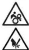
Warning of pull-in hazard

Warning of hot surface

Warning of cutting hazard

Read operating instructions

WEEE disposal marking
1.1 Intended use
ROWELD P160-630B Professional models are only to be used for producing welded joints on PE - PP and PVDF tubes according to the technical data. The user bears sole responsibility for any damage caused by improper use.
1.2 General power tool safety warnings

WARNING! Read all safety warnings, instructions, illustrations and specifications provided with this power tool.
Failure to follow all instructions listed below may result in electric shock, fire and/or serious injury.
Save all warnings and instructions for future reference.
The term "power tool" in the warnings refers to your mains-operated (corded) power tool or battery-operated (cordless) power tool.
1) Work area safety
a) Keep work area clean and well lit. Cluttered or dark areas invite accidents.
b) Do not operate power tools in explosive atmospheres, such as in the presence of flammable liquids, gases or dust. Power tools create sparks which may ignite the dust or fumes.
c) Keep children and bystanders away while operating a power tool. Distractions can cause you to lose control.
2) Electrical safety
a) Power tool plugs must match the outlet. Never modify the plug in any way. Do not use any adapter plugs with earthed (grounded) power tools. Unmodified plugs and matching outlets will reduce risk of electric shock.
b) Avoid body contact with earthed or grounded surfaces, such as pipes, radiators, ranges and refrigerators. There is an increased risk of electric shock if your body is earthed or grounded.
c) Do not expose power tools to rain or wet conditions. Water entering a power tool will increase the risk of electric shock.
d) Do not abuse the cord. Never use the cord for carrying, pulling or unplugging the power tool. Keep cord away from heat, oil, sharp edges or moving parts. Damaged or entangled cords increase the risk of electric shock.
e) When operating a power tool outdoors, use an extension cord suitable for outdoor use. Use of a cord suitable for outdoor use reduces the risk of electric shock.
f) If operating a power tool in a damp location is unavoidable, use a residual current device (RCD) protected supply. Use of an RCD reduces the risk of electric shock.
3) Personal safety
a) Stay alert, watch what you are doing and use common sense when operating a power tool. Do not use a power tool while you are tired or under the influence of drugs, alcohol or medication. A moment of inattention while operating power tools may result in serious personal injury.
b) Use personal protective equipment. Always wear eye protection. Protective equipment such as a dust mask, non-skid safety shoes, hard hat or hearing protection used for appropriate conditions will reduce personal injuries.
c) Prevent unintentional starting. Ensure the switch is in the off-position before connecting to power source and/or battery pack, picking up or carrying the tool. Carrying power tools with your finger on the switch or energising power tools that have the switch on invites accidents.
d) Remove any adjusting key or wrench before turning the power tool on. A wrench or a key left attached to a rotating part of the power tool may result in personal injury.
e) Do not overreach. Keep proper footing and balance at all times. This enables better control of the power tool in unexpected situations.
f) Dress properly. Do not wear loose clothing or jewellery. Keep your hair and clothing away from moving parts. Loose clothes, jewellery or long hair can be caught in moving parts.
g) If devices are provided for the connection of dust extraction and collection facilities, ensure these are connected and properly used. Use of dust collection can reduce dust-related hazards.
h) Do not let familiarity gained from frequent use of tools allow you to become complacent and ignore tool safety principles. A careless action can cause severe injury within a fraction of a second.
4) Power tool use and care
a) Do not force the power tool. Use the correct power tool for your application. The correct power tool will do the job better and safer at the rate for which it was designed.
b) Do not use the power tool if the switch does not turn it on and off. Any power tool that cannot be controlled with the switch is dangerous and must be repaired.
c) Disconnect the plug from the power source and/or remove the battery pack, if detachable, from the power tool before making any adjustments, changing accessories, or storing power tools. Such preventive safety measures reduce the risk of starting the power tool accidentally.
d) Store idle power tools out of the reach of children and do not allow persons unfamiliar with the power tool or these instructions to operate the power tool. Power tools are dangerous in the hands of untrained users.
e) Maintain power tools and accessories. Check for misalignment or binding of moving parts, breakage of parts and any other condition that may affect the power tool's operation. If damaged, have the power tool repaired before use. Many accidents are caused by poorly maintained power tools.
f) Keep cutting tools sharp and clean. Properly maintained cutting tools with sharp cutting edges are less likely to bind and are easier to control.
g) Use the power tool, accessories and tool bits etc. in accordance with these instructions, taking into account the working conditions and the work to be performed. Use of the power tool for operations different from those intended could result in a hazardous situation.
h) Keep handles and grasping surfaces dry, clean and free from oil and grease. Slippery handles and grasping surfaces do not allow for safe handling and control of the tool in unexpected situations.
5) Service
a) Have your power tool serviced by a qualified repair person using only identical replacement parts. This will ensure that the safety of the power tool is maintained.
2 Technical Data
P160B P200B P250B P355B P500B P630B
Basic unit:
Pipe welding range ∅ (mm) .....40-160 ....63-200 ...90-250 ....90-355 .... 200-500 ..315-630
Pipe capacity ....SDR series see welding tables + observe pressure max. hydraulic unit
Cylinder stroke, max (mm) 100 100 150 150 200 200
Total cylinder surface (cm²) .....3,53 .....3,53 .....6,26 .....6,26 .....14,13 .....14,13
Leading dimensions:
Length (mm) 705 675 810 795 1300 1300
Width (mm) 370 370 485 600 900 1060
Height (mm)....300....400....415....535....800....920
Weight max* (kg) 30,2 27,5 56,7 77,9 235 319,9
* incl. reduction clamp inserts for the smallest pipe diameter
| Trimmer unit: | |||||||
| Power supply 115 V (Hz) (A) | 230 V 50/60 3,5 | 230 V 50/60 2,9 | 230 V 50/60 3,5 | 230 V 50/60 3,7 | 400 V, 3~400 V, 2,55 | ||
| Rated power input/output (W) | 750/470 | 630/425 | 750/470 | 1050/650 | 1210/750 | 1770/1100 | |
| Rotary speed (min-1) | 660 | 950 | 660 | 726 | 140 | 140 | |
| Idle running speed milling disc (min-1) | 126 | 165 | 85 | 66 | 31 | 24 | |
| Noise pressure level dB(A) LpA | KpA | 82 | 3 | 83 | 3 | 82 | 3 | 83 | 3 | 48 | 3 | 52 | 3 | |
| Sound power level dB(A) LWA | KWA | 93 | 3 | 94 | 3 | 93 | 3 | 94 | 3 | 59 | 3 | 63 | 3 | |
| Weight (kg) | 7,6 | 7,0 | 15 | 22,4 | 68 | 123 | |
| Heating plate: | |||||||
| Power supply 115 V (Hz) (W) | 230 V 50/60 800 | 230 V 50/60 1000 | 230 V 50/60 1500 | 230 V 50/60 2500 | 400 V 50/60 4000 | 400 V 8000 | |
| Heating plate - diameter (mm) | 200 | 230 | 300 | 380 | 540 | 660 | |
| Weight (kg) | 3,3 | 3,9 | 5,5 | 9,1 | 32 | 49 | |
| Carrying frame: | |||||||
| Weight (kg) | 4,7 | 4,3 | 8,2 | 9,6 | 55 | 70 | |
| P160B, P200B, P250B, P355B | P500B, P630B | ||||||
| Hydraulic unit: | |||||||
| Power supply | 230 V - 50 Hz - 2,5 A | 230 V - 50 Hz - 5,6 A | |||||
| 230 V - 60 Hz - 2,5 A | 230 V - 60 Hz - 5,6 A | ||||||
| Rated power input/output (W) | 580/ 370 | 1290/ 750 | |||||
| 670/ 370 | 1200/ 750 | ||||||
| Pump capacity (l/min) | 2,8 | 5,65 | |||||
| 2,45 | 5,1 | ||||||
| Oil tank capacity (l) | 0,7 | 0,7 | |||||
| Pressure max. (bar) | 100 | 100 | |||||
| Hydraulic - Oil | HLP - 46 (no.: 53649) | ||||||
| Dimensions (LxWxH, mm) | 540 x 340 x 340 | 540 x 340 x 340 | |||||
| Noise pressure level dB(A) LpA | KpA | 74 | 3 | 77 | 3 | |||||
| Sound power level dB(A) LWA | KWA | 85 | 3 | 88 | 3 | |||||
| Weight (kg) | 28 | 29 | |||||
| P160B | P200B | P250B | P355B | P500B | P630B | ||
| Overall length: | |||||||
| Total connected load (kW) | 2,1 | 2,0 | 2,9 | 4,0 | 6,7 | 11,3 | |
| Transport case dimensions: | |||||||
| Length (mm) | 1200 | 1200 | 1200 | 1200 | 2240 | 2240 | |
| Width (mm) | 800 | 800 | 800 | 800 | 1300 | 1300 | |
| Height (mm) | 900 | 900 | 900 | 900 | 1500 | 1500 | |
| The noise level during operation can exceed 85 dB (A). Wear hearing protection! | |||||||
3 Function of the Unit
3.1 Description
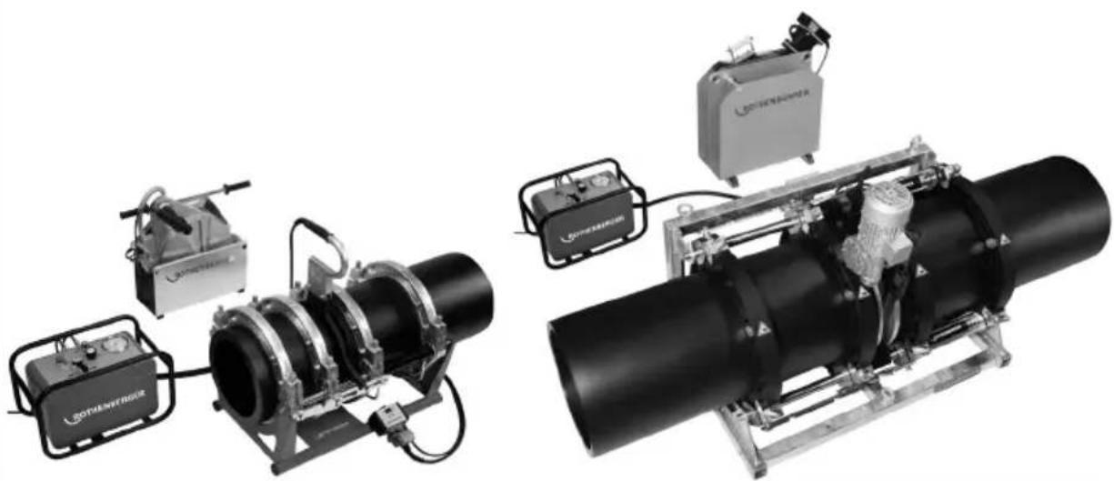
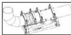
ROWELD P160-630B Professional are compact, portable heating plate butt fusion welding machines that were specially designed for use at the construction sites and in particular in pipe trenches. Of course, the tools are very well suited for use in the workshop.
Welding of pipe-pipe connections, T-joints, pipe bends and welding neck can be made.
The essential machine components are:
Basic unit, reduction clamp insets, hydraulic unit, trimmer unit, heating plate, carrying frame.
When joining welding necks always use the flange adapter (optional accessory, must be ordered separately).
ROWELD P160-250B: When welding pipe bends with a narrow radius of the maximum diameter of the machine, this bevelled upper clamping tool should be used as an accessory.
ROWELD P500-630B: To insert and remove the trimmer and the heating plate we recommend using the electrical hoist (optional accessory, must be ordered separately).
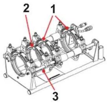
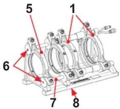
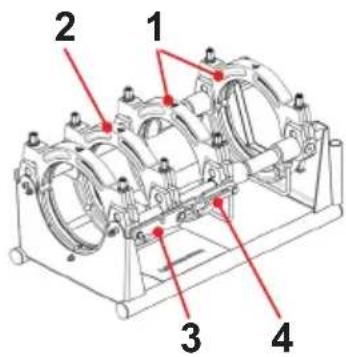
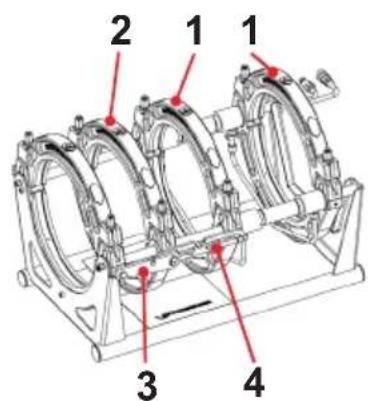
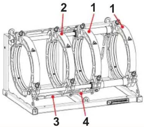
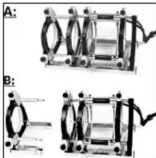
3.1.1 Basic unit (A)
1 Movable clamps 5 Replaceable clamps
2 Sliding clamps 6 Mounting screw upper
3 Spacer with locking notch 7 Spacer
4 Heating element take-off device 8 Mounting screw lower
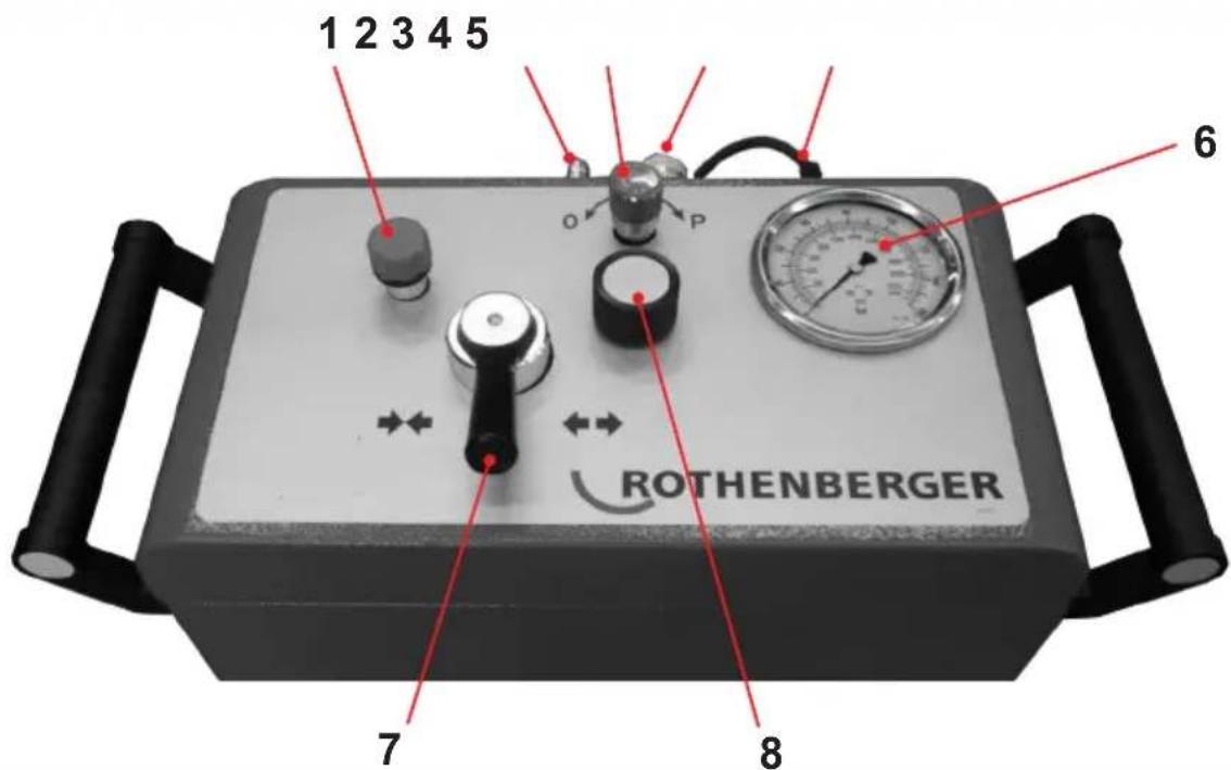
3.1.2 Hydraulic unit (B)
1 filler neck and dip stick 5 mains cable
2 fast-on connector 6 manometer
3 relief valve 7 control lever, left-close-right-open
4 fast-on coupling sleeve 8 pressure adjustment valve
The hydraulic unit allows the operator to operate the welding machine and perform the functions indicated by the following symbols:

To close the clamps press the control lever to the left. The moving and pressure build-up speed dependent on the angle of rotation

To open the clamps press the control lever to the right. The moving speed dependent on the angle of rotation

Pressure adjusting valve for milling pressure, beat forming pressure, heating pressure and cooling pressure. The manometer provides information on the regulated pressure

Pressure relief valve. Anti-clockwise turn can lowered the pressure. The lowering speed dependent from the number of turns. Right turn pressure hold
3.2 Operating instructions
The welding machines are suitable for operation at ambient temperatures between -10^ and +40^ .
They are suitable for a stationary power supply of 230 V 50/60 Hz and 400 V 50/60 Hz. If a power generator is used, the welder must clarify the required power with the manufacturer of the generator.

In accordance with national or EU ordinances and guidelines, e. g. DVS 2212, Section I, only duly qualified and authorised personnel are allowed to operate the ROWELD welding machines!
3.2.1 Putting into operation

Please read through the operating instructions and safety instructions attentively before you put the butt fusion welding machine into operation!

Do not use the heating element in explosive environments or bring it into contact with easily flammable materials!
Stay a safe distance away from the machine. Do not stand or reach into the machine. Keep other people away from the work area!

Before every start-up, check the oil level of the hydraulic unit. The oil level must be between the min. and max. marking on dipstick in the oil filler cap. If necessary, add HLP 46 hydraulic oil!

Transport and set the hydraulic unit only in a horizontal position. If it is set at an angle, oil escapes from the vented plugs with the dipstick!
→ Connect the hydraulic unit to the basic unit with both hydraulic hoses.

Protect the quick couplings from contamination. Replace leaky couplings immediately!
→ Connect the trimmer unit, hydraulic unit and heating plate mains plugs to the power outlet/supply specified on the type plates.
For P160-250B:
The red "Stand by" diode on the heating element lights up, which means: voltage is being applied. Switch on the heating element on the hand grip using the large press-button (lights up green) and set the desired temperature using the "+" or "-" button (160°C to 285°C / 320°F to 545°F).
Heating is displayed on the hand grip by the yellow diode. Horizontal bars also appear on the temperature indicator. The yellow diode goes out shortly before reaching the set nominal temperature (tolerance +/-3°C / 5.4°F) and the green one lights up. The heating element is usable after a further 10 minutes. Note: upon first reaching the nominal temperature the set value can be exceeded for short time.
→ Check the temperature using an external temperature measuring instrument. If there are deviations it means that the heating element must be re-calibrated: press the “+” and “-” button simultaneously and then set the difference using the “+” or “-” button.
If "Er1" appears this means the electronics are defective. For "Er2" the resistance thermometer is either defective or not connected. Send the device to an authorised ROTHENBERGER specialist workshop.

Risk of serious injury! The heating plate can reach temperatures of over 290^ C / 554^ F! We highly recommend storing the heating plate in the designated carrying frame immediately after use!
For P355B:
→ Turn on the main switch of the control box. The switch lights up green and the actual temperature of the hotplate is shown on the display. Use the – and + keys to set the desired temperature between 160°C and 270°C / 320°F and 518°F.
When the set temperature is reached, the display jumps from "set" to "actual", and the "heat" display blinks. The heating element is ready to use after another 10 minutes.
→ Check the temperature with a temperature measurement device.
The temperature regulator is optimally set at the factory. If the actual surface temperature on the heating element does not reflect the temperature shown, an offset can be performed. For this, set the rocker switch to 0, press the – and + keys, and turn the rocker switch on. The display shows “OFF”, “SET” and then the set offset value. Use the – and + keys to set the offset appropriately, and save it by pressing – and +. Then the current value is shown again.
For P500-630B:
→ Switch on master switch in the control box / heating plate (the switch lights green when power supply properly connected). Set required temperature (cf. temperature controller).
The display generally indicates the actual temperature value. In accordance with national ordinances and guidelines, e. g. DVS, the heating plate is ready after maintaining the setpoint temperature for at least 10 minutes.
→ Check the temperature with a temperature measurement device.

Risk of serious injury! The heating plate can reach temperatures of over 300^ C / 572^ F! We highly recommend storing the heating plate in the designated carrying frame immediately after use!
The welding machine is equipped with a Type 400 digital temperature controller.
The digital temperature controller has been ideally configured and set before leaving our factory. To set temperature simply press the F key until “_SP” is indicated in the display. The operator can now adjust the setpoint temperature between 0-300°C / 32-572°F with the arrow keys.
If no keys are pressed, the display indicates the actual temperature, the controller automatically sets the new temperature parameter. As long as the actual temperature is lower than the set-point temperature, the red arrow flashes (low). If the actual value is larger than the setpoint value, the red arrow flashes (high). If the actual temperature corresponds with the setpoint temperature, the green bar illuminates. Should the actual surface temperature of the heating plate not correspond with the actual temperature indicated, it is possible to enter an “offset”. To define the offset, press and hold the F key until “InP” appears in the display (approx. 7 sec.); release F key, then press the F key as many times as required until “oFS” appears. Correct this value as required. To save the new settings, press and hold F key until the actual value reappears in the display.

Warning! Do not change any other heating plate parameters!
Factory settings:
| Menü „CFG“„S.tu“ 0„h.Pb“ 1.0„h.lt“ 0.68„h.dt“ 0.17„h.P.H“ 100„rst“ 0„P.rE“ 0„SoF“ 0„Lb.t“ 0„Lb.P“ 25„FA.P“ 0 | Menü „InP“„Ctr“ 8„tYP“ 16„FLt“ 0.1„FLd“ 0.5„dP.S.“ 0„Lo.S“ 0„HI.S“ 300„oFS“ xx„HI.A“ 0„Lo.L“ 0„HI.L“ 280 | Menü „Out“„AL.n“ 0„r.o.1“ 0„r.o.2“ 0„Ct.1“ 20„Ct.2“ 20„rEL.“ 0 | Menü „PAS“„Prot“ 32 |
Note: The autotuning function could cause the details under “CFG” to deviate minutely. Should hunting occur, the autotuning function can be activated while the heating plate is cold (set the menue item “S.tu” to “2” (two) in CFG menue, the system automatically resets the parameter to “0” (zero).
For lifting the milling equipment and the heating element, use lifting device 53410 or 53323, or a suitable tool.
3.2.2 Measures for preparing welding
→ Pipes smaller than the maximum welding range (diameter) of the machine, mount the adapter clamping inserts suited for the pipe diameter with the Allen screws found in the accessories kit.
ROWELD P200B: ∅63-140mm: consisting of six wide-surface shells and two small-surface shells. ∅160-180mm: consisting of 8 wide-surface shells.
ROWELD P160-355B: consisting of six wide-surface shells and two small-surface shells.
ROWELD P500-630B: consisting of six wide-surface shells and two small-surface shells (for diameters up to 450 mm) or 8 wide-surface shells (for diameters >500 mm).
In so doing, please observe that the small-surface shells are mounted to the two lower external main clamps. These are used in the left basic clamping element below and above only for pipe to pipe bend connections.
→ Insert the plastic pipe or fitting in the clamping device (use dolly with longer pipe < 2,5m sections) and tighten brass nut on the upper clamps. Adjust brass nuts (tighten or loosen) to compensate for any ovalness.
For P200B:
→ The machine is operated with 4 basic clamping jaws in the case of pipes/ pipe connections (welding position A).
→ The 4th basic clamping jaw can be removed in the case of narrow pipes/ fitting connections (welding position B). To do this, initially remove the screws (3) and then slightly loosen the screws (5). The 4th jaw can now be pulled out together with the sub-construction. Finally, unscrew the spacers (4) and replace them by the screws (3).
→ For pipe-to-pipe connections, the two spacers must be engaged in both left clamping elements (standard configuration at delivery).
natural_image
Mechanical assembly diagrams showing two configurations labeled A and B, with no visible text or symbols.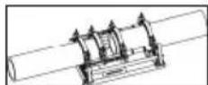

Attention: Under no circumstances should the spacers be installed diagonally offset!
The pipes are each held by two clamping elements.
→ P160B: For pipe-to-fitting connections, the two spacers must be engaged in both middle clamping elements.
→ P250-355B: For pipe-to-fitting connections, the two spacers must be engaged in both middle clamping elements, and the heating element take-off device is suspended into the left clamping elements. When some fittings are being processed in certain positions, such as horizontal bends or welding necks, it is necessary to remove the heating element take-off device.
→ P500-630B: For pipe-to-fitting connections, the spacers must be swivelled to the other side and engaged in the middle clamping elements

Attention: Under no circumstances should the spacers be installed diagonally offset!
The pipe is inserted into three clamping elements, and the fitting is held by one clamping element. Thus, the movable clamping element can be shifted on the rod as space requirements demand during clamping.
→ Verify secure fit by moving the workpieces together.

Stay a safe distance away from the machine. Do not stand or reach into the machine. Keep other people away from the work area!
→ Check to ensure that the heating plate has reached the setpoint operating temperature.

CAUTION! To guarantee uniform heat distribution over the entire heating element, the heating element must not be used until at least 10 minutes after it reaches the target temperature. Check and verify the temperature with a temperature meter and readjust if necessary!
→ Position the electrical trimmer between the two workpieces.

P500-630B: Verify the direction of rotation! The machines were polarized to turn clockwise before leaving our factory!
→ Switch on trimmer unit. The planing discs should turn in the cutting direction; if not, use suitable tools to change over the phase inverter in the mains plug.
Risk of serious injury! During operation trimmer unit, stay a safe distance away from the machine, and do not reach into the rotating knife. Use trimmer in working position only and return it into the designated carrying frame immediately after use. Ensure that the safety switch functions properly at all times to avoid any accidental starting of the trimmer away from the basic machine!
→ Turn the pressure adjustment valve counter-clockwise all the way.
→ Press the control lever leftward and slowly increase the milling pressure to the optimal value.

An excessively high milling pressure can lead to overheating and damage to the miller drive. When the milling drive is overloaded or at rest, raise the machine and reduce the pressure!
Once shavings with a thickness of < = 0.2mm are steadily exiting the milling machine, press the control lever rightward and guide the machine apart.
→ Turn off the milling equipment, and wait for the planing disks to stop. Remove the milling equipment from the basic machine, and place it in the storage case.
→ Bring the work pieces together, and let up on the pressure by opening the pressure release valve.
→ Check to see that the welding surfaces are flat, parallel and axially aligned.
Should the joint surfaces show any misalignment, repeat the trimming procedure. For best results the workpiece ends should not be mismatched by more than 10% of the wall thickness and the maximum gap between the joint surfaces no more than 0.5 mm. This recommendation does not release you from your obligation to observe national welding guidelines. Clear away any remaining shavings with a clean brush.

CAUTION! Do not touch the trimmed, ready to weld surfaces. Ensure that the surfaces are free of any and all containments and foreign objects!
3.2.3 Welding

Risk of injury! Keep a safe distance from the machine when mechanically closing clamps and moving workpieces. Keep hands, limbs and objects such as clothing, tools etc. away from running machine!
→ While moving workpiece ends to welding position, read the workpiece drag pressure from the manometer on the hydraulic unit.
The workpiece drag pressure is the minimum amount of pressure required to set the workpiece – depending on weight and length – in axial motion. This value must be precisely determined; it will be necessary to engage and disengage the machine and workpieces several times and to set the pressure adjustment valve until the machine almost comes to a standstill. Add the drag pressure to the conformation, heat-penetration and joint pressure.
Insert the heating plate into the basic unit between the two workpiece ends and make sure that the heating plate's supports are seated in the notches on the take-off device.
→ Engage the machine, set and maintain the required conformation pressure plus drag pressure.
→ As soon as sufficient bead has formed around the entire circumference of the workpiece ends, slowly release the pressure by slowly opening the relief valve.
→ Set the pressure so that workpiece ends have uniform almost pressure less contact to the heating plate (warm up).
→ Now close the relief valve. Ensure that the workpiece ends still have contact with the heating plate.
→ After the warm-up phase, disengage workpieces, remove the heating plate and re-engage the workpieces. Increase the pressure linear to the respective joint pressure and maintain that pressure until the joint is fully cooled.
→ Regularly check the pressure and pump it back up when necessary. If the pressure loss is excessive, have the hydraulic system checked.

CAUTION: Press and hold the control lever for the first 20 to 100 seconds then release (neutral switch position)!
→ Put the heating element back into the storage case.
→ After the joint has fully cooled, slowly release the pressure by opening the relief valve, unclamp the workpieces and remove from the machine.
→ Disengage the basic unit, write protocol. The machine is now ready for the next welding cycle.
All welding parameters can be found in the enclosed welding tables.
3.2.4 Putting out of operation
→ Switch off heating plate.

Let the heating element cool or stow it in such a way that no adjacent materials can be ignited!
→ Remove trimmer unit, heating plate and hydraulic unit mains plugs from power outlet and roll up cables.

Transport and set the hydraulic unit only in a horizontal position. If it is set at an angle, oil escapes from the vented plugs with the dipstick!
→ Disconnect and roll up hydraulic hoses.

Important! Protect couplings from damage and dirt!
3.3 General requirements
As weather and ambient conditions can seriously effect welding procedures and joints, it is essential to duly observe national welding guidelines and ordinances, e. g. DVS Guideline 2207, Sections 1, 11 and 15.
Welding requires continuous and due supervision and monitoring!
3.4 Important information on welding parameters
For welding parameters such as temperature, pressure and time, consult your national welding guidelines and ordinances, e. g. DVS Guideline 2207, Sections 1, 11 and 15.
Ordering: DVS Media GmbH, Aachener Str. 172, 40223 Düsseldorf
Postfach 10 19 65, 40010 Düsseldorf, Tel.: +49 (0) 211 / 15 91 – 0
Email: media@dvs-hg.de internet: www.dvs-media.info
In the event of doubt, consult the pipe manufacturer for material-specific welding parameters.
The welding parameters specified in the welding tables are strictly reference values. ROTHEN-BERGER cannot assume any liability for their accuracy or completeness!
The compensation and joint pressure values specified in the welding tables were calculated using the following formula:
pressure P [bar] = welding surface A [mm^2] x welding factor SF [N/mm^2]
surface of cylinder Az [cm^2] × 10
Welding factors (SF): PE = 0,15 N/mm ^2 , PP = 0,10 N/mm ^2 , PVDF = 0,10 N/mm ^2
4 Care and Maintenance
To ensure that the welding machine functions properly, observe the following maintenance recommendations:
- The guide rods must be kept free of dirt and grime. Replace guide rods whenever surface shows signs of erosion or damage, otherwise hydraulic system may loose pressure.
- Trimmer unit, heating plate, hydraulic unit may only be supplied with the voltage specified on the type plates.
- To achieve perfect welding results, it is essential to keep the heating plate clean. If the surface is damaged or shows signs of erosion, the surface must be recoated or replaced. Material residues on the heating plate surface reduces the non-sticking properties of the coating. Remove all residues with non-linting paper and detergent with one Ethanol content >99.8% (according to DVS 2207) (heating plate must be cool!).
- Before every start-up, check the oil level of the hydraulic unit (oil level should lie between full and empty marks). Replenish hydraulic oil whenever necessary (HLP – 46, no.: 53649).
- Change hydraulic oil (HLP – 46, no.: 53649) every six months.
- To avoid malfunctions, regularly check the hydraulic unit for leaks, proper fit of connections as well as the power cable for signs of damage or wear.
-
Protect the fast-on couplings on both the hydraulic unit as well as the hydraulic hoses from dirt and grime. Remove any dirt or foreign objects prior to connecting.
-
The trimmer unit is equipped with two bi-directional blades. Rotate or replace blades whenever trimming performance is no longer up to expectations.
- Always ensure that the pipe and workpiece ends, in particular the butt surfaces are clean. Dirt or other foreign substances will shorten the serviceable life of the blades considerably.

Pursuant to welding guidelines the welding machine must be inspected annually by the manufacturer or an authorized service workshop. Machines subjected to above average use or strain should be inspected at shorter intervals!
5 Accessories
You can find suitable accessories in the main catalog or at www.rothenberger.com
6 Customer service
The ROTHENBERGER service locations are available to help you (see listing in catalog or online) and replacement parts and service are also available through these same service locations. Order your accessories and spare parts from your specialist retailer or using RO SERVICE+ online: 📞 + 49 (0) 61 95/ 800 8200 📄 + 49 (0) 61 95/ 800 7491 ✉ service@rothenberger.com - www.rothenberger.com
7 Disposal
Components of the unit are recyclable material and should be put to recycling. For this purpose registered and certified recycling companies are available. For an environmental friendly disposal of the non-recyclable parts (e.g. electronic waste) please contact your local waste disposal authority.
Do not dispose of power tools and batteries/rechargeable batteries into household waste.
For EU countries only: According to the Directive 2012/19/EU on waste electrical and electronic equipment and its transposition into national law, power tools that are no longer usable, and, according to the Directive 2006/66/EC, defective or drained batteries must be collected separately and disposed of in an environmentally correct manner.
Only for United Kingdom: According to The Waste Electrical and Electronic Equipment Regulations 2013 (SI 2013/3113) (as amended) and the Waste Batteries and Accumulators Regulations 2009 (SI 2009/890) (as amended), products that are no longer usable must be collected separately and disposed of in an environmentally friendly manner.
P160B, P200B, P250B, P355B P500B, P630B
Unité hydraulique:
Poids (kg)....28....29
P160B P200B P250B P355B P500B P630B
natural_image
Two mechanical diagrams labeled A and B showing different configurations of a device with no visible text or symbols.natural_image
Three mechanical diagrams labeled A, B, and C showing different configurations of a mechanical assembly (no text or symbols present)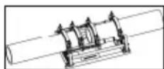

natural_image
Three mechanical diagrams labeled A, B, and C showing different configurations of a device with no visible text or symbols.natural_image
Mechanical assembly diagrams showing two configurations (A and B) with no visible text or symbols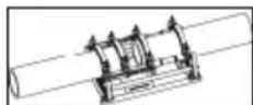

natural_image
Three mechanical diagrams labeled A, B, and C showing different configurations of a mechanical assembly (no text or symbols present)

natural_image
Two mechanical diagrams labeled A and B showing different configurations of a clamp or spring device (no text or symbols present)

natural_image
Three mechanical diagrams labeled A, B, and C showing different configurations of a device with no visible text or symbols.Długość (mm)....705....675....810....795....1300....1300
Szerokość (mm) ......370 ......370 ......485 ......600 ......900 ......1060
P160B, P200B, P250B, P355B P500B, P630B
natural_image
Two mechanical diagrams labeled A and B showing different configurations of a clamp or spring device (no text or symbols present)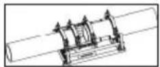

service@rothenberger.com - www.rothenberger.com
7 Utylizacja
natural_image
Three mechanical diagrams labeled A, B, and C showing different configurations of a mechanical assembly (no text or symbols present)P160B, P200B, P250B, P355B P500B, P630B
Leadott (W)....580/370....1290/750 670/370 1200/750
natural_image
Two mechanical diagrams labeled A and B showing structural components with no visible text or symbols.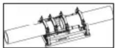
service@rothenberger.com - www.rothenberger.com
7 Ártalmatlanítás
P160B, P200B, P250B, P355B P500B, P630B
natural_image
Two mechanical clamping setups labeled A and B, showing components with no visible text or symbols.D-65779 Kelkheim / Germany
Telefon +49 6195 / 800 - 0
Telefax +49 6195 / 800 - 3500
info@rothenberger.com

- ROWELD P160-630B Professional
- Hydraulikaggregat Professional / hydraulic unit professional
- Intro
- EU-DECLARATION OF CONFORMITY
- DECLARATION EU DE CONFORMITÉ
- Inhalt Seite
- Entsorgung
- Technical Data 16
- Function of the Unit 17
- Care and Maintenance 23
- Accessories 24
- Customer service 24
- Disposal 24
- Markings in this document
- Explanation of symbols Labels
- Intended use
- General power tool safety warnings
- Technical Data
- Function of the Unit
- Description
- Basic unit (A)
- Hydraulic unit (B)
- Operating instructions
- Putting into operation
- For P160-250B:
- For P355B:
- For P500-630B:
- Measures for preparing welding
- For P200B:
- Welding
- Putting out of operation
- General requirements
- Important information on welding parameters
- Care and Maintenance
- Accessories
- Customer service
- Disposal
- Unité hydraulique:
- P160B, P200B, P250B, P355B P500B, P630B
- Utylizacja
- Ártalmatlanítás
Brand : ROTHENBERGER
Model : ROWELD P160B
Category : Plastic welding