CVC1525G - Cooker DOMETIC - Free user manual and instructions
Find the device manual for free CVC1525G DOMETIC in PDF.

| Product type | Combined hob with sink |
| Brand | Dometic |
| Model | CVC1525G |
| Category | Cooker |
| Dimensions (W x D x H) | 600 x 450 x 140 mm |
| Gas supply | Butane (G30) or Propane (G31) (pressure according to country) |
| Electrical supply | 12 V DC, 1 A (for ignition) |
| Number of burners | 1 |
| Burner type | S (small) |
| Burner power | 1.1 kW |
| Gas consumption | 80 g/h |
| Ignition | Electronic (spark button) |
| Safety | Flame supervision device (FSD), automatic shut-off when closing the lid |
| Glass lid | Yes, with soft-close hinges |
| Integrated sink | Yes |
| Main functions | Gas cooking, washing |
| Maintenance | Clean with a soft damp cloth. Consult the website for stainless steel and glass instructions |
| Recommended annual check | Yes, by a qualified professional |
| Nozzle replacement | Possible by a professional for adaptation to gas type |
| Warranty | Legal (according to applicable legislation) |
| Certification | CE |
| Intended use | Indoor (caravan, motorhome); do not use as heater |
Frequently Asked Questions - CVC1525G DOMETIC
User questions about CVC1525G DOMETIC
0 question about this device. Answer the ones you know or ask your own.
Ask a new question about this device
Download the instructions for your Cooker in PDF format for free! Find your manual CVC1525G - DOMETIC and take your electronic device back in hand. On this page are published all the documents necessary for the use of your device. CVC1525G by DOMETIC.
USER MANUAL CVC1525G DOMETIC
natural_image
Isometric line drawing of a multi-level mechanical or electrical assembly with no visible text, numbers, or symbols.CVH1 350, CVH1 350G, CVH1 525, CVH1 525G, CVH1525LG, CVH1 700G, CVC1 525G, CVC1700, CVC1700G, CVC1875G

Cooktop combination
Installation and Operating Manual 15

Kochfeld-Kombination

Kombinovaný varič
© 2025 Dometic Group. The visual appearance of the contents of this manual is protected by copyright and design law. The underlying technical design and the products contained herein may be protected by design, patent or pending patent. The trademarks mentioned in this manual belong to Dometic Sweden AB. All rights are reserved.
1
WARNING
2
4
5

6
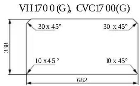
CVH135 0 (G)
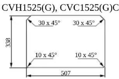
CVC1525G
CVH152 5 (G)
CVC1700(G)
CVH170 0 (G)
CVC1875G

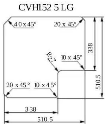
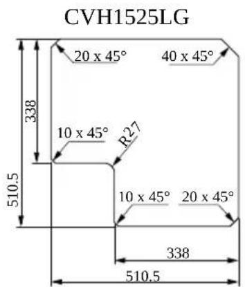
CVH1525 LG
7
8
9
CVH13 50 (G)CVC1525G
natural_image
Pure electrical circuit lines without any symbols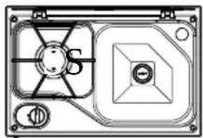
natural_image
Technical diagram of a mechanical component with no visible text or symbolsCVH152 5(G)
CVC1700(G)
natural_image
Technical diagram of a mechanical or electrical component with no visible text, numbers, or symbols.CVC1700(G)
natural_image
Technical diagram of a mechanical or electrical component with no visible text, numbers, or symbols.CVH1700G

CVC1875G
CVH1525LG
CVH1525LG
10
11
flowchart
graph TD
    A["Lock Icon"] --> B["Arrow to Left"]
    B --> C["Arrow to Right"]
    C --> D["Arrow to Right"]
    D --> E["Arrow to Left"]
    E --> F["Arrow to Right"]
    F --> G["Arrow to Right"]
    G --> H["Arrow to Left"]
    H --> I["Arrow to Right"]
    I --> J["Arrow to Right"]
    J --> K["Arrow to Left"]
    K --> L["Arrow to Right"]
    L --> M["Arrow to Right"]
    M --> N["Arrow to Left"]
    N --> O["Arrow to Right"]
    O --> P["Arrow to Right"]
    P --> Q["Arrow to Left"]
    Q --> R["Arrow to Right"]
    R --> S["Arrow to Right"]
    S --> T["Arrow to Left"]
    T --> U["Arrow to Right"]
    U --> V["Arrow to Right"]
    V --> W["Arrow to Left"]
    W --> X["Arrow to Right"]
    X --> Y["Arrow to Right"]
    Y --> Z["Arrow to Left"]
12
13
14
English
1 Important notes
Please read these instructions carefully and follow all instructions, guidelines, and warnings included in this product manual in order to ensure that you install, use, and maintain the product properly at all times. These instructions MUST stay with this product.
By using the product, you hereby confirm that you have read all instructions, guidelines, and warnings carefully and that you understand and agree to abide by the terms and conditions as set forth herein. You agree to use this product only for the intended purpose and application and in accordance with the instructions, guidelines, and warnings as set forth in this product manual as well as in accordance with all applicable laws and regulations. A failure to read and follow the instructions and warnings set forth herein may result in an injury to yourself and others, damage to your product or damage to other property in the vicinity. This product manual, including the instructions, guidelines, and warnings, and related documentation, may be subject to changes and updates. For up-to-date product information, please visit documents.dometic.com.
2 Explanation of symbols
A signal word will identify safety messages and property damage messages, and also will indicate the degree or level of hazard seriousness.

DANGER!
Indicates a hazardous situation that, if not avoided, will result in death or serious injury.

WARNING!
Indicates a hazardous situation that, if not avoided, could result in death or serious injury.

CAUTION!
Indicates a hazardous situation that, if not avoided, could result in minor or moderate injury.

NOTICE!
Indicates a situation that, if not avoided, can result in property damage.

NOTE Supplementary information for operating the product.
3 Safety instructions
Preliminary notes
- Prior to installation, ensure that the local distribution conditions (nature of the gas and gas pressure) and the adjustment of the device are compatible.
- The adjustment conditions for this device are stated on the label (or data plate).
- This device is not connected to a combustion products evacuation device. It shall be installed and connected with current installation regulations. Particular attention shall be given to the relevant requirements regarding ventilation.
General safety

WARNING! Explosion hazard
This device may only be repaired by qualified personnel. Inadequate repairs may cause serious hazards.
This device must be installed in accordance with any national regulations in force in the country of use.
Do not modify the device.
Do not remove or replace any components of this device.
The gas hose has to be changed if required by the national regulations.
Do not twist, stretch, pinch, or apply any other load to the gas supply hose.

WARNING! Suffocation hazard
Operating this device in an unventilated area will reduce the amount of oxygen in this area.
This device must only be used in a well ventilated space.
This device is for cooking purposes only. It shall not be used for other purposes, for example room heating.

WARNING! Fire hazard
Do not leave this device unattended when hot or in use.
Children must be supervised to ensure that they do not play with the device.
Keep a suitable fire extinguisher ready. Ensure that the fire extinguisher is checked by skilled personnel in regular intervals.

WARNING! Burn hazard
Keep hands, face and hair away from burners.
Do not wear loose clothing or allow long hair to hang freely while lighting or using this device.
Keep children and pets away.
Carefully monitor all activity around this device to avoid burns or other injuries.

WARNING! Health hazard
This device can be used by children aged from 8 years and above and persons with reduced physical, sensory or mental capabilities or lack of experience and knowledge if they have been given supervision or instruction concerning use of the device in a safe way and understand the hazards involved.

CAUTION! Risk of injury
In case of glass lid breakage:
- Shut off immediately all burners and any electrical heating element and isolate the device from the power supply.
- Do not touch the device surface.
- Do not use the device.

NOTICE! Damage hazard
Close the glass lid before beginning a journey.
Turn off all the burners before closing the glass lid.
Keep heavy or sharp objects away from the surface of the glass lid.
Safety precautions when handling liquid gas

WARNING! Explosion hazard
After use always disconnect the liquid gas cylinder.
Store liquid gas cylinders away from heating or cooking devices and other light or heat sources in a well-ventilated area out of the reach of children.
Never store liquid gas cylinders in unventilated areas or below ground level (funnel-shaped holes in the ground).
Never store liquid gas cylinders in buildings such as garages.
Any indoor storage must comply with national regulations.
Do not store liquid gas cylinders on their side.
Keep liquid gas cylinders away from direct sunlight. The temperature should not exceed 50°C.
Operating the device safely
Fig. 1 on page 3

DANGER! Hazard of carbon monoxide poisoning
The process of burning liquid gas produces carbon monoxide which accumulates inside enclosed areas. Only use this device with sufficient ventilation.

DANGER! Suffocation hazard
The use of a gas cooking appliance results in the production of heat, moisture and products of combustion in the room in which it is installed.
- Ensure that the kitchen is well ventilated especially when the device is in use.
- Keep natural ventilation holes open or install a mechanical ventilation device (e.g. a mechanical extractor hood).
Prolonged intensive use of the appliance may require additional ventilation, for example the increasing of mechanical ventilation where present, additional ventilation to safely remove the products of combustion to outside air whilst also providing room air changes with additional ventilation. Consult a professional before installation of the additional ventilation.

WARNING! Explosion hazard
Do not use this device if it is leaking, damaged or does not operate properly.
Never use the device in the following situations:
- At petrol stations
- On ferry boats
- While transporting the vehicle in which the device is installed with a transport vehicle or tow truck
In case of fire shut off the gas supply.
Do not place chemicals, flammable materials or spray aerosols near this device.
Never use a naked flame to check for gas leaks.
In case there is a smell of gas:
- Do not attempt to light this device.
- Extinguish any naked flames.
- Turn off the gas supply.
- Disconnect the device from the gas supply.
- Have the gas system checked by a specialist.
Only attach or detach the gas container away from a naked flame, pilot light or other source of ignition and only when this device is cool to touch.
Before using the gas container, check that the seal between this device and the gas container is in place and in good condition.
If the seal is damaged or worn, do not use this device.
Turn off the gas supply at the gas container after use.

WARNING! Fire hazard
Do not use or store flammable materials in or near this device (e.g. paper, textiles).
Do not place any objects other than cookware on or against this device.
Keep flammable objects away from the burner.
Position cookware handles as follows:
- Never allow cookware handles to extend beyond the edge of the device.
- Turn cookware handles inward, but not extending over other burners.
Do not excessively heat grease or oil.
Only use dry pot holders to handle hot cookware.
Turn off the device before removing the cookware.
Only operate this device when an adult can attend to it.

WARNING! Burn hazard
Accessible parts may be very hot. Keep young children away.

CAUTION! Burn hazard
Use protective gloves when handling hot components.
Leave this device to cool down properly before you touch it with bare hands.
If igniting a burner manually:
- Use long matches or a suitable lighter.
- Remove your hand quickly as soon as the burner ignites.
The use of alcohol or prescription or non-prescription drugs may impair your ability to properly assemble or safely operate this device.
4 Scope of delivery
| Description |
| Cooktop combination |
| Fastening screws |
| Siphon and rubber seal |
| Installation and operating manual |
5 Intended use
The gas cooktops and combinations are intended for installation in a kitchen or countertop in caravans or motor homes.
• Cooking and frying food in suitable cookware
- Use with gas of the allowed gas category (see chapter Technical data on page 23)
- Use as a space heater
- Outdoor use
- Use on boats
This product is only suitable for the intended purpose and application in accordance with these instructions.
This manual provides information that is necessary for proper installation and/or operation of the product. Poor installation and/or improper operation or maintenance will result in unsatisfactory performance and a possible failure.
The manufacturer accepts no liability for any injury or damage to the product resulting from:
- Incorrect installation, assembly or connection, including excess voltage
- Incorrect maintenance or use of spare parts other than original spare parts provided by the manufacturer
• Alterations to the product without express permission from the manufacturer - Use for purposes other than those described in this manual
Dometic reserves the right to change product appearance and product specifications.
6 Technical description
6.1 Specifications of the different models
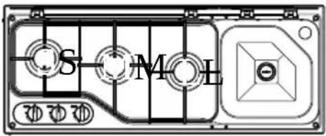
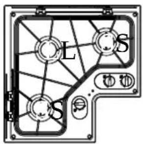
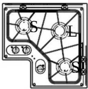
Depending on the model, the cooktops have one to three burners. The combinations consist of cooktops with one to three burners and a sink.
Find the detailed specification in the following table:
| Model | No. of burners | Glass lid | L-Shape | Sink |
| CVH 13 50 | 1 | - | - | - |
| CVH 13 50G | 1 | x | - | - |
| CVH 15 25 | 2 | - | - | - |
| CVH 15 25G | 2 | x | - | - |
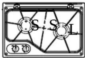
| CVH 15 25LG | 3 | x | x | - |
| CVH 17 00G | 3 | x | - | - |
| CVC 1525 G | 1 | x | - | x |
| CVC 1700 | 2 | - | - | x |
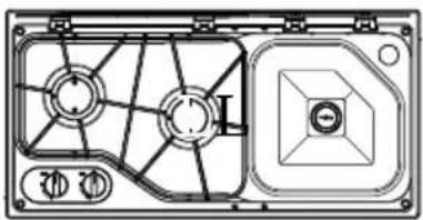
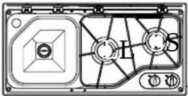
| CVC 1700 G | 2 | x | - | x |
| CVC 1875 G | 3 | x | - | x |
6.2 Control panel
Fig. 2 on page4
| Icon | Explanation | Icon | Explanation |
| A/M | LowName | [000AH] | Flame off |
7 Installation
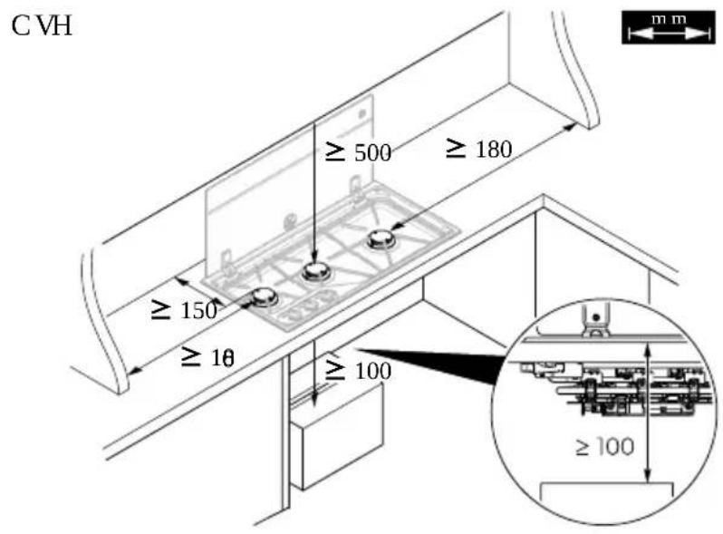
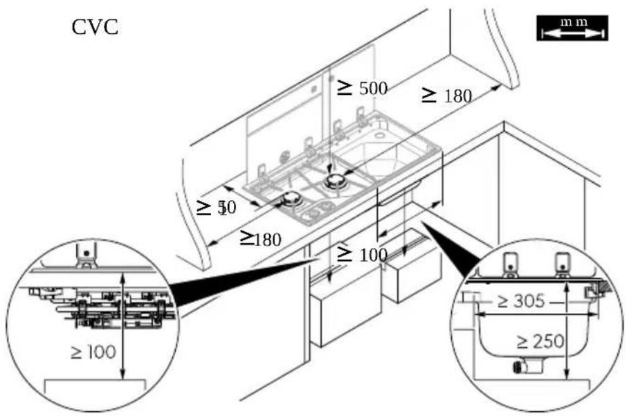
7.1 Installation location
The installation location must have air vents with a cross-section of at least 150 cm^2 .
Observe the minimum distances.
Fig. 4 on page 6
Ensure that there are no drafts at the installation location.
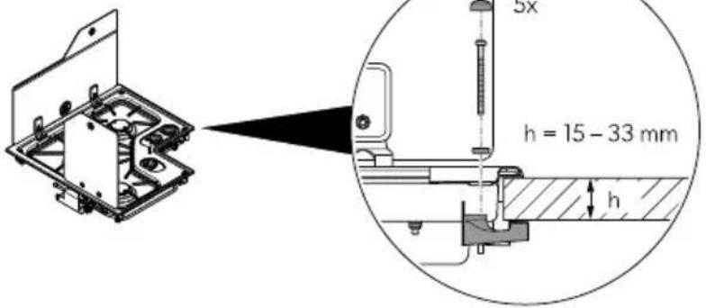
7.2 Installation steps
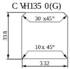
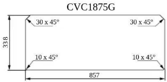
- Create a cut-out in the countertop.
Fig. 5 on page 7
- Attach a rubber seal between the countertop and the device.

NOTE Contact the manufacturer if the device is not supplied with a rubber seal.
- Fasten the device in the countertop.
Fig. 6 on page 8
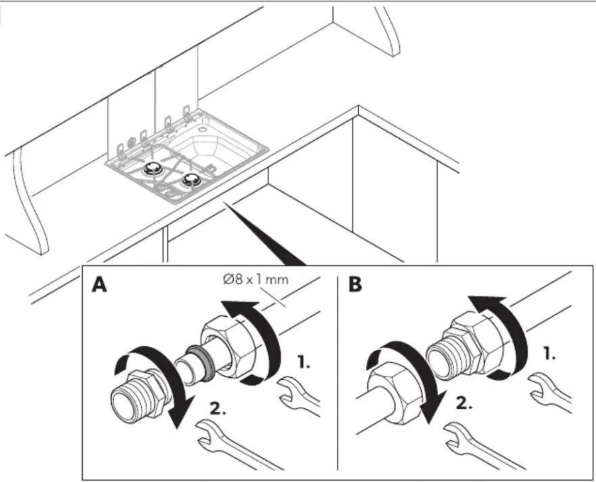
7.3 Connecting the device to the gas supply

The assembly and installation of the gas connection must be performed by a qualified person who has demonstrated skill and knowledge related to the construction, installation and operation of gas appliances and has received safety training to identify and avoid the hazards involved.

WARNING! Explosion hazard
Only use propane or butane gas containers with a certified pressure reduction valve and suitable head.
Compare the pressure information on the data plate with the pressure information on the propane or butane gas containers.
Avoid any stress on the gas pipe system during and after installation.
- Observe the national requirements.
-
Only use a steel pipe ∅ 8 x 1 mm (welded, seamless steel or stainless steel) for the connection.
-
Fasten the gas line to the side or rear wall of the surrounding furniture parts so that no loads are placed on the actuators.
• The entire gas line must be free of stress. -
The supply connection point shall be accessible with the device installed.
-
Connect the pipes as shown.
Fig. 7 on page 9
- Attach a sign above the device with the following text:
WARNING!
When cooking, additional ventilation must be provided, for example, by opening windows near the device.
The device must not be used as a space heater.
- Open the gas supply.
- Check all connections for leaks with soapy water.

WARNING! Explosion hazard
Never check for leaks with an open flame or near sources of ignition.
√ There are no leaks if no bubbles form.
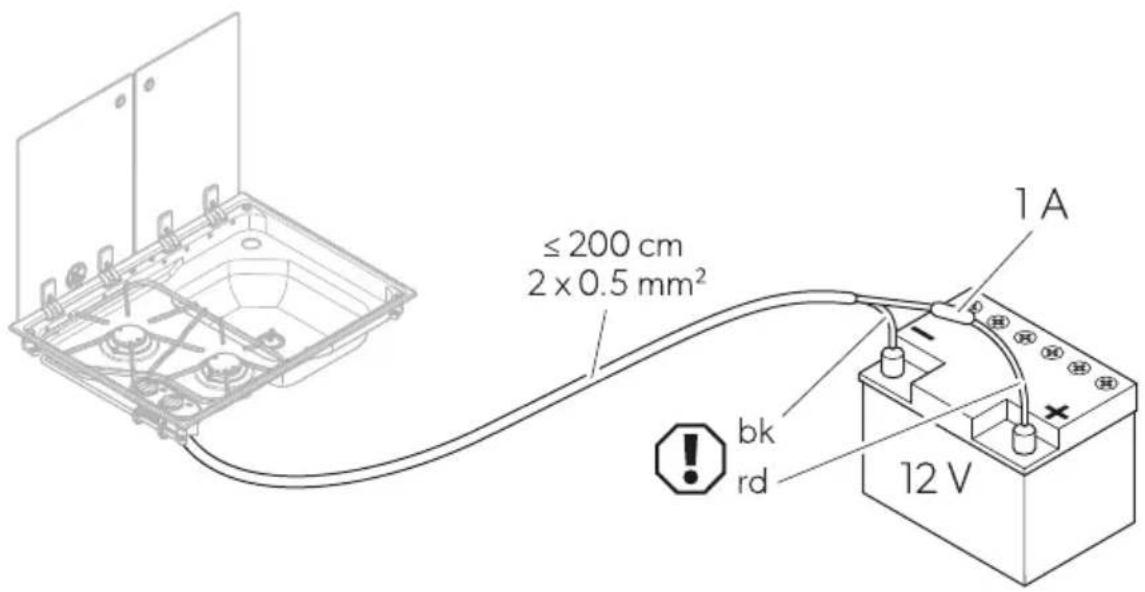
7.4 Connecting the device to the DC power supply

NOTE The flame supervision device and the safety function for the glass lid (see chapter Function on page 19) only works if the DC power supply is connected with correct polarity.
- Connect the device as shown.
Fig. 8 on page 9
bk black
rd red
- Add a 1 A fuse in the plus line near the battery.
8 Using the cooktop combination

CAUTION! Burn hazard
All parts of the device except the control panel become very hot while cooking. Do not touch the hot parts of the device during and after use. Leave the device to cool down properly.
Do not use the sink during cooking. Let the device cool down properly before using the sink.
Remove any plastic accessories from the sink before cooking.

CAUTION! Burn hazard
If the device has glass lids and the glass lid of the sink is closed while cooking, keep a minimum distance of 10 mm between the cookware and the glass lid of the sink.

Burn hazard
Do not shut the lid when the burner is alight.
8.1 Switching on

DANGER! Hazard of carbon monoxide poisoning
Before switching on the device, ensure that the area is sufficiently ventilated.
During use, there must be opened air vents with a cross-section of at least 150 cm ^2 in the installation room. These vents can be closed when the device is not in use.

WARNING! Explosion hazard/Fire hazard
Only use gas of the allowed gas category (see chapter Technical data on page 23). Do not use any other fuels.
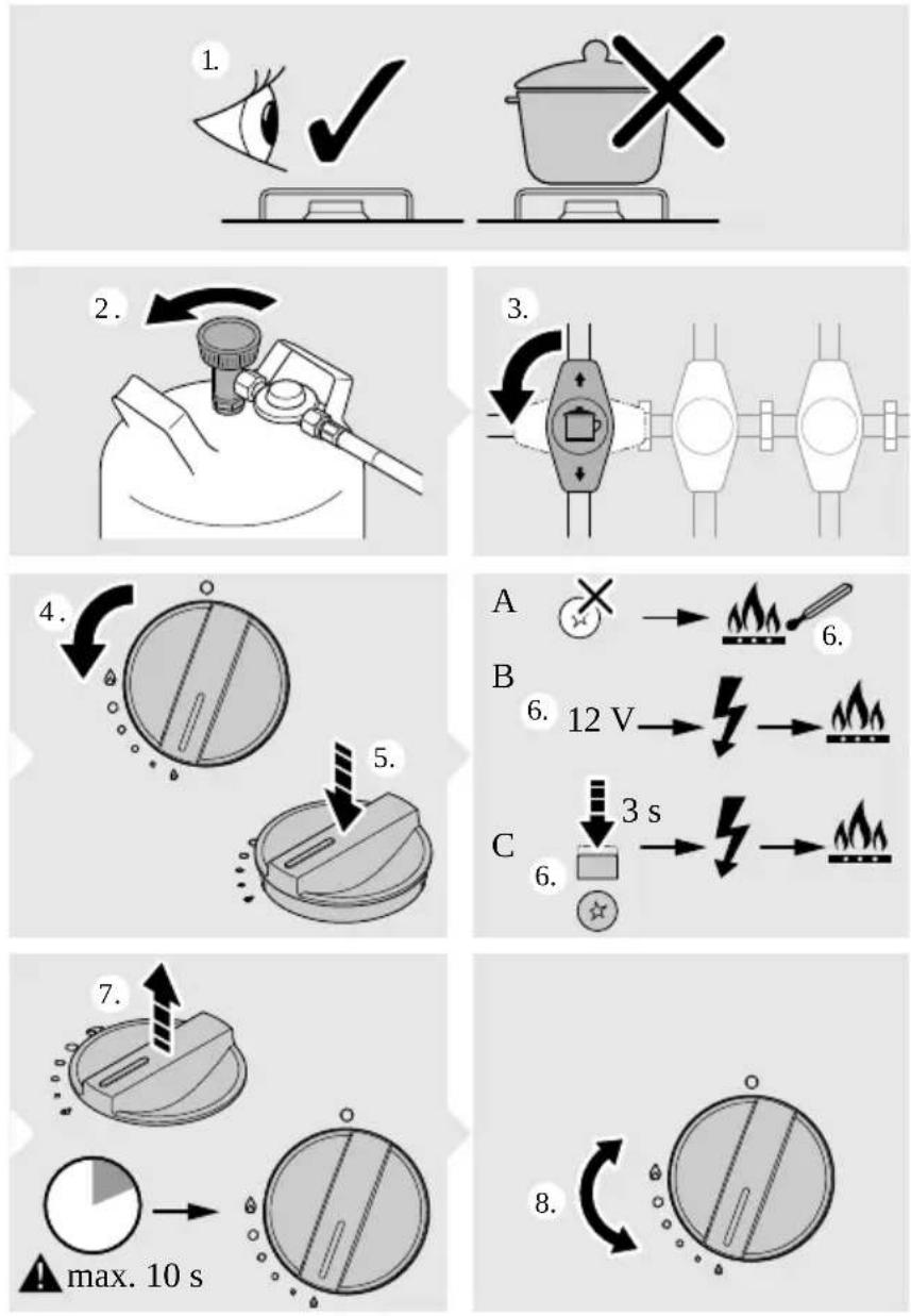
- Choose suitable cookware for the selected burners according to the following table:

Fig. 9 on page 10
| Burner(9) | Cookware diameter |
| S 10 ... 16 cm |  |
| M 12 ... 18 cm |  |
| L 16 ... 22 cm |
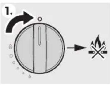
- Switch the cooktop on as shown.

Fig. 10 on page 11
Depending on the model, the burners are ignited differently:
- Manual ignition: 10, A
• Electrical ignition: 📄. 10, B -
Piezo ignition: 10, C
-
Verify the correct function of the burner by visually inspecting the flame.
Depending on the type of gas used, the flame should appear as follows:
• Propane (G31): Flame with a blue internal pin point and a clear outline.
- Butane (G30): Flame with a slightly yellow tip when turning on the burner. The yellow tip intensifies as the burner heats up.
-
If the flame does not look as described, switch the cooktop off (see chapter Switching off on page 21) and proceed as follows:
-
Check the burner for soiling and clean the burner if necessary (see chapter Cleaning the device on page 22).
- Check the quality of the gas and replace the gas container if necessary (see chapter Replacing the gas container on page 22).
8.2 Switching off

CAUTION! Risk of injury
Do not switch off the device by closing the glass lid.
Switch the cooktop off as shown.
Fig. 11 on page 11
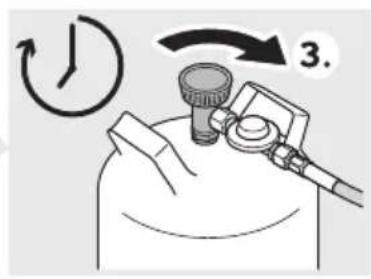
8.3 Replacing the gas container

WARNING! Explosion hazard
Only replace the gas container in places with good ventilation.
Ensure that there is no source of ignition nearby.
Only change the gas container when the device is not in use and the gas supply to the device is switched off.
- Switch the device off by turning the knob to the zero position.
- Close the valve on the gas container.
- Replace the gas cylinder according to the instructions from the gas fitting manufacturer.
9 Cleaning and maintenance

CAUTION! Burn hazard
Leave the device to cool down properly before cleaning, checking or maintaining the device.
9.1 Cleaning the device
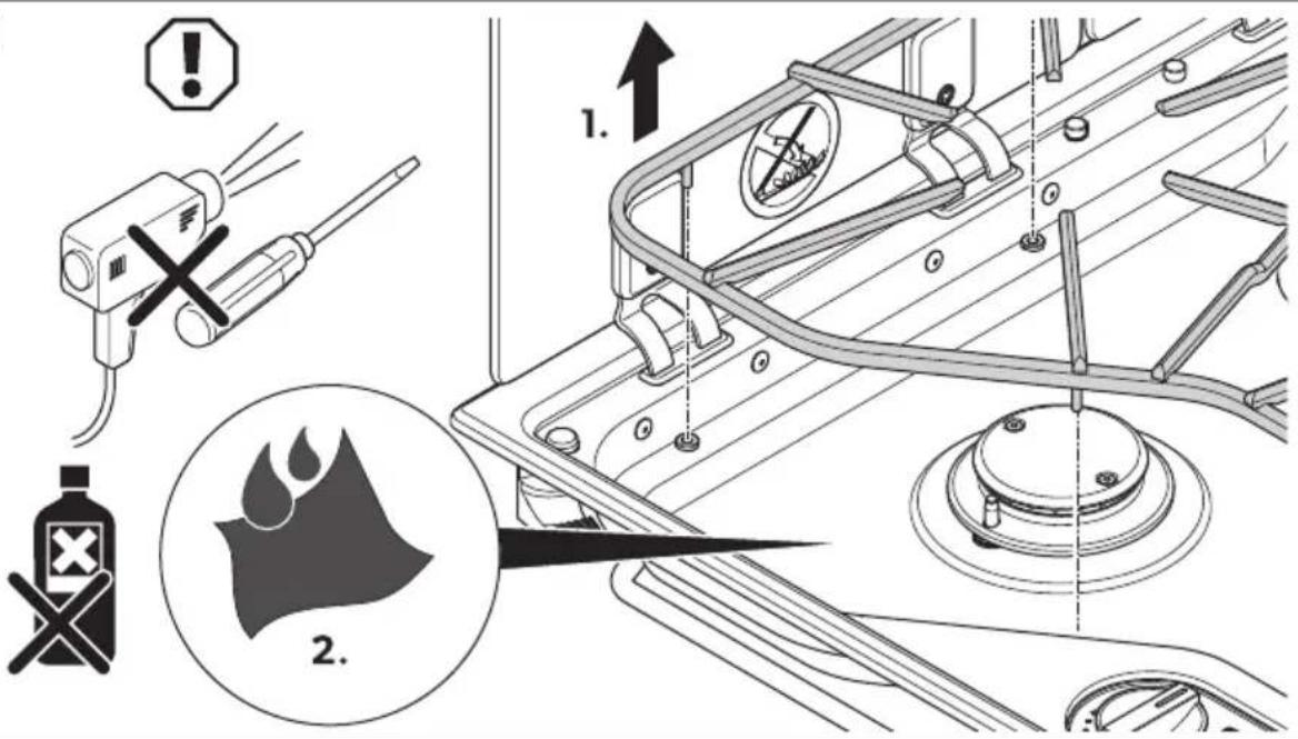
Fig. 12 on page 12
- Remove the pan support ( 12, 1).
- Clean the device with a soft, damp cloth (12, 2).

Find additional care instructions for stainless steel and glass surfaces online on qr.dometic.com/beVsW0.
9.2 Annual safety check

The assembly and installation of the gas connection must be performed by a qualified person who has demonstrated skill and knowledge related to the construction, installation and operation of gas appliances and has received safety training to identify and avoid the hazards involved.
For safety reasons, have the device checked by a qualified person every year for proper function. Any defects must be repaired.
9.3 Replacing the nozzles

The assembly and installation of the gas connection must be performed by a qualified person who has demonstrated skill and knowledge related to the construction, installation and operation of gas appliances and has received safety training to identify and avoid the hazards involved.
Let a qualified person replace the nozzles as shown.
Fig. 13 on page 13 Fig. 14 on page 14
10 Disposal

Place the packaging material in the appropriate recycling waste bins, wherever possible. Consult a local recycling center or specialist dealer for details about how to dispose of the product in accordance with the applicable disposal regulations.
11 Warranty
The statutory warranty period applies. If the product is defective, please contact the manufacturer's branch in your country (see dometic.com/dealer) or your retailer.
For repair and warranty processing, please include the following documents when you send in the device:
• A copy of the receipt with purchasing date
• A reason for the claim or description of the fault
Note that self-repair or nonprofessional repair can have safety consequences and might void the warranty.
Domestic CVC, CVH EN
12 Technical data
| Gas category | propane (G31), butane (G3Q) |
| Appliance category | I_2,P(30) |
| Gas connection pressure | AT, DE, BG, CY, DK, EE, FL, GR, HU, IS, LT, IS, MT, NL, NO, RO, SE, SI, SK, AL, HR, MK, TR: 30 mbar propane (G31) 30 mbar butane (G30) |
| Appliance category | I_2 + , propane/butane |
| Gas connection pressure | BE, CH, CY, CZ, ES, FR, GB, GR, IE, IT, LT, PL, PT, SI, SK, AL, MK, TR: 37 mbar propane (G31) 28 mbar ... 30 mbar butane (G30) |
| Connection voltage(modals with electronic ignition only) | 12V=(1A fuse) |
| Dimensions(W x H x D) | 600 × 140 × 450 mm |
| Inspection/certification | CE |
Fig. 9 on page10
| Model | Burner S |  | BurnerM |  | Burner L |  | |||
| * | ** | *** | * | ** | *** | * | ** | *** | |
Deutsch
1 Wichtige Hinweise
7.1 Installationsort
6 Description technique
Domestic CVC, CVH ES
12 Datos técnicos
WAARSCHUWING! Brandgevaar
WAARSCHUWING! Brandgevaar
Domestic CVC, CVH NL
Domestic CVC, CVH SV
12 Tekniska data
| Gaskluss | propan (G31); butan (G30) |
| Apparatikategori | I_2 , B/P(30) |
| Gasanslutringgistryck | AT, DE, BG, CY, DK, EE, FI, GR, HU, IS, LT, LV, MT, NL, NO, RO, SE, SI, SK, AL, HR, MK, TR30 mbar propan(G31)30 mbar butan (G30) |
| Apparatikategori | I_2+ , propan/butan |
| Gasanslutringgistryck | BE, CH, CY, CZ, ES, FR, GB, GR, IE, IT, LT, PL, PT, SI, SK, AL, MK, TR37 mbar propan (G31)28 mbar ... 30 mbar butan (G30) |
| An slutningsupinning (galler endast modeller media elektronik tändning) | 12 V = (1 A sikring) |
| Dimensions (B x H x D) | 600 × 140 × 450 mm |
| Beaktning/ certifiering | CE |
bild. 9 sida10
| Modell | Brännare S |  | Brännare M |  | Brännare L |  | |||
| * | ** | *** | * | ** | *** | * | ** | *** | |
Norsk
1 Viktige merknader
Domestic CVC, CVH HR
12 Tehnički podaci
| Kategorieja plina | propan (G31); butan (G30) |
| Kategorieja uređaja | I_2B/P(30) |
| Priključnitlak plina | AT, DE, BG, CY, DK, EE, FI, GR, HU, IS, LT, LV, MT, NL, NO, RO, SE, SI, SK, AL, HR, MK, TR30 mbar propan(G31)30 mbar butan (G30) |
| Kategorieja uređaja | I_2v , propan/butan |
| Priključnitlak plina | BE, CH, CY, CZ, ES, FR, GB, GR, IE, IT, LT, PL, PT, SI, SK, AL, MK, TR37 mbar propan (G31)28 mbar ... 30 mbar butan (G30) |
| Priključnimapon(samo modeli selektro-nidom paljenjem) | 12 V = (1 A aiguran) |
| Dimenzije (šr. xvis. x dub.) | 600 × 140 × 450 mm |
| Ispitivanje/certifikacija | CE |
sl. 9 na stranici 10
| Model | Plamenik S |  | Plamenik M |  | Plamenik L |  | |||||
| x | xx | xx x | x | xx | xx xx | x | xx | xx | xx xx | ||
Türkçe
1 Önemli notlar
Domestic CVC, CVH BG
12 Технически данни
| Видналека | пропан (G31), булан (G30) |
| Категориянауреда | I_2 ,B/P(30) |
| Напогане на пасажатакрыка | AT, DE, BG, CY, DK, EE, FI, GR, HU, IS, LT, LV, MT, NL, NO, RO, SE, SI, SK, AL, HR, MK, TR30 mbar пропан (G31)30 mbar булан (G30) |
| Категориянауреда | I_2 , пропан/Булан |
| Напогане на пасажатакрыка | BE, CH, CY, CZ, ES, FR, GB, GR, IE, IT, LT, PL, PT, SI, SK, AL, MK, TR37 mbar пропан (G31)28 mbar ... 30 mbar булан (G30) |
| Напроконнима свъриване (саво заимодем с электронно запаване) | 12 V = (1 A предыт antigen) |
| Размери (Ш) × В × Д) | 600 × 140 × 450 mm |
| Исплекцие/серлифидиране | CE |
Wenon-Kawlan's own 100% ownership of the company

BRĪDINĀJUMS! Apdegumu risks
BRĪDINĀJUMS! Apdegumu risks
dometic.com/sales-offices