
PTBM 400 B1 - Drill PARKSIDE - Free user manual and instructions
Find the device manual for free PTBM 400 B1 PARKSIDE in PDF.

| Product type | Bench drill |
| Brand | Parkside |
| Model | PTBM 400 B1 |
| Nominal input voltage | 230 V~, 50 Hz |
| Power consumption | 350 W (S1) / 400 W (S6 40 %) |
| No-load speed (chuck) | 600 - 2650 min⁻¹ |
| Motor speed | 1400 min⁻¹ |
| Spindle travel | 50 mm |
| Chuck capacity | 1.5 mm to 13 mm (B16 taper) |
| Weight (with accessories) | approx. 14.1 kg |
| Protection class | I |
| Protection type | IPXO |
| Integrated laser | Class 2, 650 nm, < 1 mW |
| Workable materials | Metal, wood, plastic, tile |
| Main functions | Drilling, belt speed adjustment, depth stop, tilting table up to 45° |
| Included equipment | Chuck, chuck key, Allen key, vise, laser, batteries, guard, lifting arm |
| Maintenance and cleaning | Unplug before maintenance; clean with soft brush; lubricate moving parts; do not use chemical cleaners |
| Safety | Emergency stop, gear cover with lock, protective device, automatic stop if cover open |
| Warranty | 3 years (France and Belgium) |
| Spare parts availability | Parts available via www.grizzlytools.shop during warranty period |
Frequently Asked Questions - PTBM 400 B1 PARKSIDE
User questions about PTBM 400 B1 PARKSIDE
0 question about this device. Answer the ones you know or ask your own.
Ask a new question about this device
Download the instructions for your Drill in PDF format for free! Find your manual PTBM 400 B1 - PARKSIDE and take your electronic device back in hand. On this page are published all the documents necessary for the use of your device. PTBM 400 B1 by PARKSIDE.
USER MANUAL PTBM 400 B1 PARKSIDE
natural_image
Industrial drill press machine with control panel and base mount (no visible text or labels)

Tischbohrmaschine / Bench Pillar Drill / Perceuse d'établi PTBM 400 B1
DE AT CH
Tischbohrmaschine
Translation of the original instructions
NL BE
Tafelboormachine
Before reading, unfold the page containing the illustrations and familiarise yourself with all functions of the device.
FR BE
bar
(U/min): | (U/min): | |---| | 2650 | | 1800 | | 1300 | | 900 | | 600 |Intended purpose......25
General description......25
Extent of the delivery 25
Description of functions....25
Overview....25
Technical Data....26
Notes on safety......26
Symbols and icons 27
General Safety Directions for Power Tools....27
Safety information for drills ....30
Additional safety instructions ....30
Safety Instructions for Handling the Laser 30
Safety Instructions for Handling Batteries....30
Assembly....31
Operation 32
Setting up 32
Selecting the speed 32
Checking the V-belts 33
Tensioning the V-belts....33
Adjusting the Drilling Bench......33
Preselecting the Drilling Depth .....33
Changing the Bit....33
Drilling 34
Adjusting the laser 34
Inserting/replacing laser batteries....34
General Information ....34
Switching on and off 34
Clamping the Workpieces....35
Removing Blockages......35
Cleaning and maintenance......35
Cleaning....35
Maintenance 36
Storage......36
Transport 36
Waste disposal and environmental protection ....36
Replacement parts/Accessories ..37
Troubleshooting 37
Guarantee 38
Repair Service....39
Service-Center......39
Importer 39
Translation of the original EC declaration of conformity ....292
Exploded Drawing ......307
Introduction
Congratulations on the purchase of your new device. With it, you have chosen a high quality product.
During production, this equipment has been checked for quality and subjected to a final inspection. The functionality of your equipment is therefore guaranteed. It cannot be ruled out that residual quantities of water or lubricants will remain on or in the equipment/hose lines in isolated cases. This is not a fault or defect and it represents no cause for concern.

The operating instructions constitute part of this product. They contain important information on safety, use and disposal.
Before using the product, familiarise yourself with all of the operating and safety instructions. Use the product only as described and for the applications specified.
Keep this manual safely and in the event that the product is passed on, hand over all documents to the third party.
Intended purpose
The bench drill is designed for drilling in metal, wood, plastic and tiles. Straight shank drills with a drilling diameter from 1.5 mm to 13 mm can be used.
The device is intended to be used by do-it-yourselfers. It was not designed for heavy commercial use.
The tool is not to be used by persons. under the age of 16. Children over the age of 16 may use the tool except under supervision.
The manufacturer is not liable for damage caused by an improper use or incorrect operation of this device.
General description
An illustration of the most important functional components can be found on the front and the back fold-out pages.
Extent of the delivery
Carefully unpack the appliance and check that it is complete. Dispose of the packaging material correctly.
- Baseplate
- Drilling bench
- Column tube
- Motor unit
- 3 drill lifting arms
- Safety device
- Drill chuck
- Drill chuck key
- Allen key
- Vice
- Laser
- Mounting screw
- 2 x 1.5 V batteries, AAA size
- 5x assembly screws
2x nuts
4x washers
2x spring washers
- Instruction Manual
Description of functions
Please refer to the descriptions below for information about the operating devices.
Overview

1 Gear cover
2 Holder for drill chuck key and Allen key
3 Locking screw for gear cover
4 Locking nut for motor unit
5 Motor unit
6 Column tube
7 Locking handle
8 3 Assembly screws
9 Baseplate
10 Retaining screw for drilling bench inclination (not visible)
11 Mounting screws for vice
12 Drilling bench
13 Vice
14 Chuck jaws
15 Angle scaling
16 Clamping screws for motor unit
17 Battery compartment, laser
18 Laser controller
19 Clamping screw for safety device
20 Drill spindle
21 Drill chuck
22 Drill lifting arm
23 Safety device
24 Emergency stop switch
25 Hand spindle guide
26 Off switch
27 On switch
GBMT
28 Depth stop with scale
29 Locking screw of the depth stop
30 Drill chuck key
31 Allen key
32 On/off switch for laser

33 Mounting screw, laser

34 V-belt
35 Spindle-side drive pulley
36 Motor side drive pulley
37 Interlock switch
Technical Data
Bench Pillar Drill ..... PTBM 400 B1
Rated input voltage U .....230 V\~, 50 Hz Idle power consumption P₀.....350 W (S1)
Power input.... 400 W (S6 40 %)* Idling speed (n _0 )
Spindle....600 - 2650 min ^-1 Motor....1400 min ^-1
Safety class ....I
Protection category......IPX0
Weight (with accessories)....14.1 kg
Drill chuck......B16 (1.5 mm to 13 mm)
Spindle stroke....50 mm
Workpiece size.....max. 60 mm Laser
Laser class....2
Laser wavelength ....650 nm
Laser power P_0 ....< 1 mW
Power supply
Laser module ..... 2 x 1.5 V Micro (AAA)
Battery....Alkaline manganese
Sound pressure level
(L_pA) 75.8 dB; K_pA = 3 dB
Sound power level ( L_WA )
measured....88.8 dB; K_WA=3 dB
* After an uninterrupted operating time of 4 minutes under load, the device must then cool down for 6 minutes in idle mode, otherwise overheating would occur.
Levels of noise and vibration were determined according to the norms and regulations in the declaration of conformity.

Wear ear protection
The specified noise emission value has been measured according to a standardised testing method and may be used for comparison with another power tool.
The specified noise emission value can also be used for a provisional assessment of the load.

Warning:
The noise emissions may deviate from the specified values during actual use of the power tool, depending on how the power tool is being used and, in particular, what kind of material is being worked on.
Safety measures for protection of the operator are to be determined that are based on an estimate of the load under the real operating conditions.
Notes on safety

Caution! When using power tools, observe the following basic safety measures for the prevention of electric shocks and the risk of injury and fire.
Please read all these instructions before using this electric tool and please keep the safety instructions.
Symbols and icons
Symbols on the device:

Warning!

Warning! Electric shock hazard. ways unplug the device before working on it.

Read the manual!

Wear ear protection

Wear eye protection

Do not wear long hair uncovered. a hair net.

Do not wear gloves.

Caution! Risk of injury from rotating parts!

Electrical machines do not belong with domestic waste

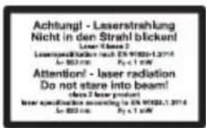
Caution! - Laser beam Do not look into the beam! Laser class 2
| (U/min):∅ (mm):∅ | ||
| < 3 | < 4 | |
| 3 - 4 | 5 - 6 | |
| 5 | 7 - 8 | |
| 6 - 8 | 9 - 10 | |
| > 8 | > 10 |
Speed table
Symbols used in the instructions:

Hazard symbols with in- formation on prevention of personal injury and property damage.

Precaution symbol with information on prevention of harm / damage.

Connect the machine to the power supply.

Pull out the mains plug.

Notice symbol with information on how to handle the device properly.

Caution! Hot surface. There is a risk of burns.

Steel
Wood
General Safety Directions for Power Tools

WARNING! Read all safety notices, instructions, illustrations and technical data that have been provided with this power tool. Omissions in the compliance with safety directions and instructions can cause electrical shock, fire and/or severe injuries.
Retain all safety directions and instructions for future use.
The term „power tool“ in the warnings refers to your mains-operated (corded) power tool or battery-operated (cordless) power tool).
1) WORK AREA SAFETY
a) Keep work area clean and well lit. Cluttered or dark areas invite accidents.
b) Do not operate power tools in explosive atmospheres, such as in the presence of flammable liquids, gases or dust. Power tools create sparks which may ignite the dust or fumes.
c) Keep children and bystanders away while operating a power tool. Distractions can cause you to lose control.
2) ELECTRICAL SAFETY
a) Power tool plugs must match the outlet. Never modify the plug in any way. Do not use any adapter plugs with earthed (grounded) power tools. Unmodified plugs and matching outlets will reduce risk of electric shock.
b) Avoid body contact with earthed or grounded surfaces, such as pipes, radiators, ranges and refrigerators. There is an increased risk of electric shock if your body is earthed or grounded.
c) Do not expose power tools to rain or wet conditions. Water entering a power tool will increase the risk of electric shock.
d) Do not abuse the cord. Never use the cord for carrying, pulling or unplugging the power tool. Keep cord away from heat, oil, sharp edges or moving parts. Damaged or entangled cords increase the risk of electric shock.
e) When operating a power tool
outdoors, use an extension cord suitable for outdoor use. Use of a cord suitable for outdoor use reduces the risk of electric shock.
f) If operation of the power tool in a damp environment is unavoidable, please use a residual current circuitry. The use of a residual current circuitry reduces the risk of an electric shock.
3) PERSONAL SAFETY
a) Stay alert, watch what you are doing and use common sense when operating a power tool. Do not use a power tool while you are tired or under the influence of drugs, alcohol or medication. A moment of inattention white operating power tools may result in serious personal injury.
b) Use personal protective equipment. Always wear eye protection. Protective equipment such as dust mask, non-skid safety shoes, hard hat, or hearing protection used for appropriate conditions will reduce personal injuries.
c) Prevent unintentional starting. Ensure the switch is in the off-position before connecting to power source and/or battery pack, picking up or carrying the tool. Carrying power tools with your finger on the switch or energising power tools that have the switch on invites accidents.
d) Remove any adjusting key or wrench before turning the power tool on. A wrench or a key left attached to a rotating part of the power tool may result in personal injury.
e) Do not overreach. Keep proper footing and balance at all times. This enables better control of the power tool in unexpected situations.
f) Dress properly. Do not wear loose clothing or jewellery. Keep your hair, clothing and gloves away from moving parts. Loose clothes, jewellery or long hair can be caught in moving parts.
g) If dust extraction and collection devices can be installed, make sure that these are connected and used correctly. Use of dust collection can reduce dust-related hazards.
h) Do not allow yourself to be lulled into a false sense of security and do not disregard the safety rules for power tools, even if you are familiar with the power tool after using it many times. Careless action can lead to serious injuries within a fraction of a second.
4) POWER TOOL USE AND CARE
a) Do not force the power tool. Use the correct power tool for your application. The correct power tool will do the job better and safer at the rate for which it was designed.
b) Do not use the power tool if the switch does not turn it on and off. Any power tool that cannot be controlled with the switch is dangerous and must be repaired.
c) Remove the plug from the wall socket and/or remove the rechargeable battery before you change the device's settings, change accessory parts or put away the power tool. Such preventive safety measures reduce the risk of starting the power tool accidentally.
d) Store idle power tools out of the reach of children and do not allow persons unfamiliar with the power tool or these instructions to operate the power tool. Power tools are dangerous in the hands of untrained users.
e) Look after the power tool and application tool carefully. Check for misalignment or binding of moving parts, breakage of parts and any other condition that may affect the power tool's operation. If damaged, have the power tool repaired before use. Many accidents are caused by poorly maintained power tools.
f) Keep cutting tools sharp and clean. Properly maintained cutting tools with sharp cutting edges are less likely to bind and are easier to control.
g) Use the power tool, accessories and tool bits etc. in accordance with these instructions, taking into account the working conditions and the work to be performed. Use of the power tool for operations different from those intended could result in a hazardous situation.
h) Keep handles and grip surfaces dry, clean and free from oil and grease. Slippery handles and grip surfaces do not permit safe operation and control over the power tool in unexpected situations.
5) SERVICE
a) Have your power tool serviced by a qualified repair person using only identical replacement parts. This will ensure that the safety of the power tool is maintained.
Safety information for drills
a) The drill must be secured. A drill that is not properly secured can move or tip over and this can cause injury.
b) The workpiece must be clamped or fastened to the workpiece support. Do not drill into workpieces that are too small for safe clamping. Holding the workpiece by hand can lead to injuries.
c) Do not wear gloves. Gloves can be caught by rotating parts or drilling chips and thus cause injuries.
d) Keep your hands away from the drilling area while the power tool is running. Contact with rotating parts or drilling chips can lead to injuries.
e) The drilling tool must rotate before you guide it to the workpiece. Otherwise the drilling tool can get caught in the workpiece, causing unexpected movement of the workpiece and injuries.
f) If the drilling tool jams, stop pressing down and switch off the power tool. Investigate and eliminate the cause of the blockage. Blocking can lead to unexpected movement of the workpiece and to injuries.
g) Avoid long drilling chips by regularly interrupting the downward pressure. Sharp metal chips can get caught and cause injuries.
h) Never remove drilling chips from the drilling area while the power tool is running. To remove chips, move the drilling tool away from the workpiece, switch off the power tool and wait for the drilling tool to stop. Use tools such as a brush or
hook to remove the chips. Contact with rotating parts or drilling chips can lead to injuries.
i) The permissible speed of insert tools with rated speed must be at least as high as the maximum speed indicated on the power tool. Accessories that run faster than the permissible speed can break and fly apart.
Additional safety instructions
- If the power tool's power cord is damaged, this must be replaced with a specially prepared power cord, which is available from the customer service organisation.
Safety Instructions for Handling the Laser
- Caution: Laser radiation - Do not look into the beam - Laser class 2
- Do not aim the laser at reflective surfaces.
- Markings and warnings are located next to the hand spindle guide (25).
Safety Instructions for Handling Batteries
- Ensure at all times that the batteries are inserted with the correct polarity (+ and -), as shown on the battery itself.
- Do not short-circuit the batteries.
- Do not charge non-rechargeable batteries.
- Do not overcharge batteries!
- Do not mix old and new batteries or batteries of a different type or from different manufacturers! Replace all batteries of a set at the same time.
-
Remove used batteries immediately from the device and dispose of them correctly!
-
Do not heat the batteries!
- Do not carry out any welding or soldering work directly on the batteries!
- Do not take the batteries apart!
- Do not deform the batteries!
- Do not throw the batteries into fire!
- Store the batteries out of the reach of children.
- Do not allow children to replace the batteries without supervision!
- Do not store the batteries close to a fire, cookers or other sources of heat. Do not place the battery in direct sunlight and do not use or store it in motor vehicles in hot weather.
- Store used batteries in the original packaging and keep them away from metal objects. Do not mix (up) unpacked batteries! Otherwise this may cause the battery to short-circuit, resulting in damage, burns or even the danger of fire.
- Remove batteries from the device if this is not going to be used for a prolonged period, unless it is to be used in emergencies!
- NEVER touch batteries which have leaked without appropriate protection. If the leaked liquid comes into contact with the skin, you should rinse off this area of the skin immediately under running water. Make sure at all events that your eyes and mouth do not come into contact with the liquid. If they do, seek medical advice immediately.
- Clean the battery contacts and the equivalent contacts in the device before inserting the batteries.
Assembly
The bench drill is supplied disassembled. Clean the column tube (6), baseplate (9), drilling bench (12), vice (13) and the drill chuck (21) beforehand, with a dry cloth.
-
Place the column tube (6) on the base-plate (9).
The red marking at the base of the column tube (6) and the recess in the baseplate (9) must line up.
Bolt the column tube (6) to the baseplate (9) with the three assembly screws (8) (size 13 mm) supplied. Tighten the assembly screws (8) moderately tight so that the threads in the baseplate (9) do not strip. -
Place the drilling bench (12) on the column tube (6). Push the drilling bench (12) into a lower position. Use the locking handle (7) to fix the drilling bench (12) in a lower position.

- Place the vice (13) on the drilling bench (12). Screw it firmly onto the drilling bench (12) by means of the enclosed assembly screws (11) (size 17 mm) together with the washer and the lock washer in the order as shown. The two assembly screws (11) should be positioned diagonally opposite each other.

- Place the motor unit (5) on the column tube (6). Secure the motor unit (5) with the two clamping screws (16) on the side using the enclosed Allen key (31).

-
Bolt the three drill lifting arms (22) into the spindle guide (25). Tighten the three hole lifting arms with a spanner (Width across flats 6).
-
Release the clamping screw (29) from the depth stop (28).

- Mount the laser on the motor unit (5) using the fixing screw (33).
Make sure that the battery compartment (A 17) is on the side of the hand spindle guide (A 25).

-
Put the safety device (23) on the upper part of the drill spindle (20).
-
Secure the safety device (23) with the clamping screw (19).
-
Fold the safety device (23) upwards. Insert the chuck (21) on the taper of the drill spindle (20). Push the drill chuck (21) onto the drill chuck tip with a few light taps. Use a plastic hammer for this purpose.
Operation

Caution! Risk of injury!
- Ensure that you have sufficient space in which to work and that you do not endanger other people.
- All hoods and protective devices must be assembled properly before commissioning.
- Disconnect the mains plug before changing the setting on the device.
Setting up
Place the bench drill on a solid surface. Bolt the machine to the substrate before putting into operation. Use the four holes in the baseplate (9) for this.

Selecting the speed
- Release the locking bolt (3) on the gear cover.
- Open the gear cover (1).
- Loosen the two locking nuts (4) of the
motor unit (5) with an open-ended spanner (size 14 mm, not included in delivery).
- Push the motor unit (5) a little towards the column tube (6) to relieve the V-belt (34).
- Place the V-belt (34) on the desired combination to reach the specified speed:
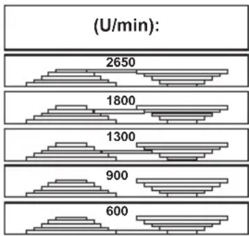
bar
| Time (U/min) | Value | |---|---| | 2650 | | | 1800 | | | 1300 | | | 900 | | | 600 | |- Tighten the locking nuts (4) again and tension the V-belt (34) so that the motor unit (5) presses backwards. The V-belt (34) is correctly tensioned when it can be pushed in about 1 cm.
- Close the gear cover (1). Fasten the locking bolt (3) on the gear cover.

The gear cover (1) is equipped with a interlock switch (37). If the gear cover (1) is not closed correctly, the device cannot be switched on.
Recommended speeds for different drill sizes and materials:
| ∅ [mm] | ∅ [mm] | [1/min] |
| < 3 | < 42650 | |
| 3 - 45 - 6 | 1800 | |
| 5 | 7 - 81300 | |
| 6 - 89 - | 10900 | |
| >8 | >10600 |
F Checking the V-belts
- Release the locking bolt (3) on the gear cover (1).
- Open the gear cover (1).
- Check the tension of the V-belt (34).
- The V-belt (34) is correctly tensioned when it gives way slightly when pressed.
- Check the V-belt (34) for tears, cuts or other damage.
- Close the gear cover (1). Fasten the locking bolt (3) on the gear cover (1).
F Tensioning the V-belts
- Release the locking bolt (3) on the gear cover (1).
- Open the gear cover (3).
- Loosen the two locking nuts (4) of the motor unit (5) with an open-ended spanner (size 14 mm, not included in delivery).
- Tighten the locking nuts (4) again and tension the V-belt so that the motor unit (5) presses backwards.
The V-belt (34) is correctly tensioned when it can be pushed in about 1 cm.
- Close the gear cover (1). Fasten the locking bolt (3) on the gear cover (1).
Adjusting the Drilling Bench
- Release the locking handle (7).
- Push the drilling bench (12) to the desired height.
- Pivot the drilling bench (12) to the desired position.
- Fasten the drilling bench (12) again with the locking handle (7).
- You can also adjust the tilt angle of the drilling bench (12). To do this, release
the retaining screw (10) (Width across flats 19) under the drilling bench (12). Tilt the drilling bench (12) as desired to the right or left up to a max. of 45^ and secure the drilling bench (12) again with the retaining screw (10).
Preselecting the Drilling Depth
- Release the locking screw from the depth stop (29).
- Lower the drilling spindle (20) with the mounted tool on to the workpiece.
- Turn the scale until the red marking arrow attached to the motor unit (5) is pointing to the zero line of the scale.
- Now turn the scale to the desired drilling depth and tighten the locking screw (29) again.
- Turn the drilling spindle (20) back to its starting position.
Changing the Bit

Remove the plug from the mains socket before changing the bit. This will prevent an accidental start-up.
- Fold the safety device (23) up.
- Release the retaining jaws of the drill chuck (21) with the drill chuck key (30) you find in the holder (2).
- Remove the bit.
- Insert a new bit.
- Tighten the retaining jaws of the drill chuck (21) with the drill chuck key (30).
- Affix the hole chuck key (30) on the holder again (2).
- Check that the bit is centred.
- Fold the safety device (23) down again.
- Carry out a brief trial run in order to check the drill for true running.

Under no circumstances must you leave the drill chuck key (30) inserted.
Drilling
- Turn the appliance on.
- Turn one of the drill lifting arms (22) anticlockwise
- The drill chuck (21) is lowered.
- Drill into the workpiece at the appropriate feed rate and to the desired depth.
- Be aware of any necessary chip breaking on the way to the desired depth.
- Move the bit slowly back to the stop position.

Adjusting the laser

Caution! - Laser beam. Do not look into the beam. Turn your head away or close your eyes to prevent looking into the laser beam. Danger of eye injury!

To adjust the laser, use a section of wood that you no longer need.
- Spot-drill the clamped workpiece. Do not make any further changes to the position of the workpiece until the laser has been adjusted.
- Turn the laser (33) on at the on/off switch.
- Set the laser cross to where the workpiece has been spot-drilled by turning the two controllers (18).

Inserting/replacing laser batteries
- Turn the laser off.
- Open the battery compartment of the laser (17) by sliding the lock upwards
and opening the compartment.
Inserting the batteries
- Insert the batteries according to the polarity indicated on the cover.
- Close and lock the battery compartment (17).
- Pull the batteries out of the battery compartment (17).
- Close and lock the battery compartment (17).
Removing the batteries
General Information

The feed rate and spindle speed are decisive for the service life of the bit.
- The cutting speed is determined by the speed of the drill spindle and by the diameter of the bit.
- In principle, therefore, the larger the bit diameter, the lower the speed that should be selected.
- For workpieces of greater strength, the cutting pressure must be higher.
- Repeated withdrawal of the bit enables easier chip removal.
- Chip removal is especially difficult in deep holes. Reduce the feed rate and speed in this case.
- To avoid excessive wear on the cutting surface of the bit, for drill holes over 8.0 mm in diameter you should first drill with a bit with a smaller diameter.
Switching on and off

Make sure that the power supply voltage matches the voltage rating indicated on the device's type plate.

Connect the machine to the power supply.

Caution! Fold the protective device (23) down before you switch on the machine.
Switching on:
1.. Press the On switch (27).
Switching off:
- Press the Off switch (26).
Emergency stop:
Press the emergency stop button (24).

After actuating the emergency stop, press the on switch (27) to start the device again.
Clamping the Workpieces
Only work on workpieces that can be securely clamped between the chuck jaws (14). The workpiece must not yield too much. Otherwise it is nor possible to apply adequate tension.
The workpiece must not be too small or too large either.
Removing Blockages
- You should always select a suitable feed rate which allows trouble-free chip breaking.
- If the bit is jammed in the workpiece, turn off the power and unplug the power cord. Turn the bit on the drill chuck anticlockwise with a little jerk to break the chip and release the bit again.
- If a fragment is produced during the processing of the workpiece, turn off the power and unplug the power cord. Use a pair of pliers and remove the fragment to prevent it flying off in an uncontrolled way.
Cleaning and maintenance

Pull the mains plug before any adjustments, maintenance or repair.

Have any work on the device that is not described in this instruction guide performed by a professional. Only use original parts. Allow the device to cool off before any maintenance or cleaning is undertaken. There is a risk of burning!
Always check the device before using it for obvious defects such as loose, worn or damaged parts, correct the positioning of screws or other parts. Exchange the damaged parts.
Cleaning

Do not use any cleaning agents or solvents. Chemical substances can etch the plastic parts of the device. Never clean the device under running water.
- Thoroughly clean the device after every use.
- Clean the ventilation openings and the surface of the device with a soft brush or cloth.
- Remove chips, dust and dirt with a vacuum cleaner if necessary.
- Lubricate moving parts regularly.
- Do not allow lubricants to come into contact with switches, V-belts, pulleys and drill lifting arms.
Maintenance
The device is maintenance free.
Storage
- Store the appliance in a dry place well out of reach of children.
- The device can be relocated over a short distance with two people. Relocating the device over a longer distance generally has to take place with a transport aid.
Transport

Do not carry the bench drill holding it on the motor unit.

Caution! Hot surface. There is a risk of burns. Only transport the machine when the motor unit (5) has cooled down completely.
If possible, carry the bench drill together with another person. Grip the baseplate (9) with one hand and stabilise the machine on the drive cover (1) with the other hand.
Waste disposal and environmental protection
Be environmentally friendly. Remove the battery from the device and take the device, battery, accessories and packaging for environmentally friendly recycling.

Electrical machines do not belong with domestic waste.

Dispose of the batteries according to local regulations. Hand in the batteries at a used battery collection point they are recycled in an environmentally friendly manner. For more information, we contact your local waste management provider or our service centre.
Directive 2012/19/EU on waste electrical and electronic equipment: Consumers are legally obliged to recycle electrical and electronic equipment in an environmentally sound manner at the end of its life. In this way, environmentally friendly and resource-saving recycling is ensured. Depending on implementation in national law, you may have the following options:
- Return to a shop,
- Hand over to an official collection point,
- Return to the manufacturer/distributor. This does not affect accessories enclosed with the old devices or tools without any electrical components.
Replacement parts/Accessories
Spare parts and accessories can be obtained at www.grizzlytools.shop If you have issues ordering, please use the contact form. If you have any other questions, please contact the service centre (see page 20).
| Position Manual | Position drawing | Description | Ordernumber |
| A 6 | 92,94 Column tube | 91104521 | |
| A 12 | 86-91,96 Drilling bench, complete | 91104522 | |
| A 13 | 97-109 | Vice | 91103342 |
| A 21 | 45 Drill chuck | 91103343 | |
| A 23 | 44 Safety device | 91103336 | |
| A 22 | 59-60 Drill lift arm x 3 | 91104525 | |
| A 30 | 61 Drill chuck key | 91104510 | |
| F 34 | 72 | V-belt (K-26.5) | 91103345 |
| 11-13 | Hinge of the gear cover | 91103346 | |
| 110 | Laser | 91099350 |
Troubleshooting
| Problem | Possible Cause | Error correction |
| Device doesn’t start | No mains voltageMain circuit breaker is tripped | Check the socket, mains supply cable,cord, mains plug; if necessary, have them repaired by a qualified electrician.Check the main fuse |
| On switch (27) / off switch (26) defective | Repair by Customer Care | |
| Motor faulty | Repair by Customer Care | |
| Strong vibrations | Motor unit (5) not fixed in place | Check V-belt tension and tighten the locking nuts (4). |
| Bit not centrally clamped | Check the bit in the drill chuck (21) | |
| Laser does not work | Batteries empty | Replace batteries (see “Replacing laser batteries”) |
| Loud squeaking noise | V-belt tension is too high | Check V-belt tension |
| Damaged V-belts (34) | Check V-belts (34) | |
| Damaged pulley | Check pulleys |
Guarantee
Dear Customer,
This equipment is provided with a 3-year guarantee from the date of purchase. In case of defects, you have statutory rights against the seller of the product. These statutory rights are not restricted by our guarantee presented below.
Terms of Guarantee
The term of the guarantee begins on the date of purchase. Please retain the original receipt. This document is required as proof of purchase.
If a material or manufacturing defect occurs within three years of the date of purchase of this product, we will repair or replace – at our choice – the product for you free of charge. This guarantee requires the defective equipment and proof of purchase to be presented within the three-year period with a brief written description of what constitutes the defect and when it occurred.
If the defect is covered by our guarantee, you will receive either the repaired product or a new product. No new guarantee period begins on repair or replacement of the product.
Guarantee Period and Statutory Claims for Defects
The guarantee period is not extended by the guarantee service. This also applies for replaced or repaired parts. Any damages and defects already present at the time of purchase must be reported immediately after unpacking. Repairs arising after expiry of the guarantee period are chargeable.
Guarantee Cover
The equipment has been carefully produced in accordance with strict quality guidelines and conscientiously checked prior to delivery.
The guarantee applies for all material and manufacturing defects. This guarantee does not extend to cover product parts that are subject to normal wear and may therefore be considered as wearing parts (e.g. V-belts, batteries) or to cover damage to breakable parts (e.g. switches).
This guarantee shall be invalid if the product has been damaged, used incorrectly or not maintained. Precise adherence to all of the instructions specified in the operating manual is required for proper use of the product. Intended uses and actions against which the operating manual advises or warns must be categorically avoided.
The product is designed only for private and not commercial use. The guarantee will be invalidated in case of misuse or improper handling, use of force, or interventions not undertaken by our authorised service branch.
Processing in Case of Guarantee
To ensure efficient handling of your query, please follow the directions below:
- Please have the receipt and item number (IAN 499273_2204) ready as proof of purchase for all enquiries.
- Please find the item number on the rating plate.
- Should functional errors or other defects occur, please initially contact the service department specified below by telephone or by e-mail. You will then receive further information on the processing of your complaint.
- After consultation with our customer service, a product recorded as defective can be sent postage paid to the service address communicated to you, with the proof of purchase (receipt) and specification of what constitutes the defect and when it occurred. In order to avoid acceptance problems and additional costs, please be sure to use only the address communicated to you. Ensure that the consignment is not sent carriage forward or by bulky goods, express or other special freight. Please send the equipment inc. all accessories supplied at the time of purchase and ensure adequate, safe transport packaging.
Repair Service
For a charge, repairs not covered by the guarantee can be carried out by our service branch, which will be happy to issue a cost estimate for you.
We can handle only equipment that has been sent with adequate packaging and postage.
Attention: Please send your equipment to our service branch in clean condition and with an indication of the defect.
Equipment sent carriage forward or by bulky goods, express or other special freight will not be accepted.
We will dispose of your defective devices free of charge when you send them to us.
Service-Center
GB Service Great Britain Tel.: 0800 404 7657
E-Mail: grizzly@lidl.co.uk
IAN 499273_2204
MT Service Malta Tel.: 80062230
E-Mail: grizzly@lidl.com.mt
IAN 499273_2204
Importer
Please note that the following address is not a service address. Please initially contact the service centre specified above.
Service-Center......59
Importateur ....59
bar
(U/min): | (U/min): | |---| | 2650 | | 1800 | | 1300 | | 900 | | 600 |Service-Center......77
Importeur 77
Service-Center....94
Importer 94
Service-Center....112
Dovozce....112
Service-Center......129
Dovozca....129
Service-Center....145
Importør 145
Fejlsøgning 145
Service-Center......163
Importador 163
Service-Center......181
Importatore ....181
| ∅ (mm):∅ | (mm): (U/min): | |
| <3 | <4 | |
| 3-4 | 5-6 | |
| 5 | 7-8 | |
| 6-8 | 9-10 | |
| >8 | >10 |
Tabella velocità
bar
(U/min): | (U/min): | |---| | 2650 | | 1800 | | 1300 | | 900 | | 600 |- Znova privijte pritrdilni matici (4) in klinasti jermen (34) napnite tako, da se enota motorja (5) potiska nazaj.
Klinasti jermen (34) je pravilno napet, če ga je mogoče vtisniti za pribl. 1 cm.
- Zaprite pokrov gonila (1). Privijte vijak pokrova gonila (3)

Pooblaščeni serviser:
Tel.: 080 080917
E-Mail: grizzly@lidl.si
(Birotehnika, Hodošček Renata s.p., Lendavska ULICA 23, 9000 Murska Sobota)
Garancijski list
Service-Center......233
Proizvođač......233
Prijevod originalne CE Izjave o podudarnosti ....303
Razina snage zvuka (L _WA )
Introducere ......234
Service-Center......251
Importator 251
Raducerea Declaratiei Originale de Conformitate CE ......304
Translation of the original EC declaration of conformity
We hereby confirm that the
Bench pillar drill
Design Series PTBM 400 B1
Serial Number
000001 - 045000
conforms with the following applicable relevant version of the EU guidelines :
2006/42/EC • 2014/30/EU • 2011/65/EU* & (EU) 2015/863
In order to guarantee consistency, the following harmonised standards as well as national standards and stipulations have been applied:
EN 62841-1:2015 • EN 62841-3-13:2017
EN 55014-1:2017/A11:2020 • EN IEC 55014-1:2021
EN 55014-2:1997/A2:2008 • EN IEC 55014-2:2021
EN 61000-3-2:2014 • EN IEC 61000-3-2:2019/A1:2021
EN 61000-3-3:2013 • EN 61000-3-3:2013/A2:2021
EN 61010-1:2010/A1:2019 • EN 60825-1:2014+A11:2021 • EN IEC 63000:2018
This declaration of conformity is issued under the sole responsibility of the manufacturer:

( Documentation Representative )


- Tischbohrmaschine / Bench Pillar Drill / Perceuse d'établi PTBM 400 B1
- Tischbohrmaschine
- Tafelboormachine
- FR BE
- Introduction
- Intended purpose
- General description
- Extent of the delivery
- Description of functions
- Overview
- GBMT
- Technical Data
- Bench Pillar Drill ..... PTBM 400 B1
- Warning:
- Notes on safety
- Symbols and icons
- Symbols on the device:
- Symbols used in the instructions:
- General Safety Directions for Power Tools
- Retain all safety directions and instructions for future use.
- 1) WORK AREA SAFETY
- 2) ELECTRICAL SAFETY
- 3) PERSONAL SAFETY
- Safety information for drills
- Additional safety instructions
- Safety Instructions for Handling the Laser
- Safety Instructions for Handling Batteries
- Assembly
- Operation
- Caution! Risk of injury!
- Setting up
- Selecting the speed
- Recommended speeds for different drill sizes and materials:
- F Checking the V-belts
- F Tensioning the V-belts
- Adjusting the Drilling Bench
- Preselecting the Drilling Depth
- Changing the Bit
- Drilling
- Adjusting the laser
- Inserting/replacing laser batteries
- Inserting the batteries
- Removing the batteries
- General Information
- Switching on and off
- Caution! Fold the protective device (23) down before you switch on the machine.
- Switching on:
- Switching off:
- Emergency stop:
- Clamping the Workpieces
- Removing Blockages
- Cleaning and maintenance
- Cleaning
- Maintenance
- Storage
- Transport
- Do not carry the bench drill holding it on the motor unit.
- Waste disposal and environmental protection
- Replacement parts/Accessories
- Guarantee
- Terms of Guarantee
- Guarantee Period and Statutory Claims for Defects
- Guarantee Cover
- Processing in Case of Guarantee
- Repair Service
- Service-Center
- Importer
- Garancijski list
- Translation of the original EC declaration of conformity
Brand : PARKSIDE
Model : PTBM 400 B1
Category : Drill