NAVA - Motorcycle Kindercraft - Free user manual and instructions
Find the device manual for free NAVA Kindercraft in PDF.

User questions about NAVA Kindercraft
0 question about this device. Answer the ones you know or ask your own.
Ask a new question about this device
Download the instructions for your Motorcycle in PDF format for free! Find your manual NAVA - Kindercraft and take your electronic device back in hand. On this page are published all the documents necessary for the use of your device. NAVA by Kindercraft.
USER MANUAL NAVA Kindercraft
chemical
Simple molecular structure diagram showing two white curved atoms inside a black oval shapeKinderkraft
natural_image
Exterior view of a modern electric vehicle with gray and orange body, no visible text or symbolsNAVA
USER GUIDE
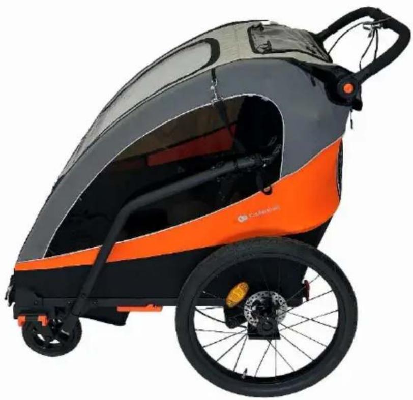
(EN) Stroller/Trailer
(CS) Kočárek/Přivěs
(DE) Buggy/Ánhänger
MANUAL DE INSTRUÇÕES
MANUAL DE UTILIZARE
text_image
SCAN TO WATCH THE VIDEO!AR....22
CS....26
DE....31
EN 36
ES 41
FR 46
HU 51
IT 56
NL....61
PL 66
PT....71
RO 76
RU 81
SK 86
SV....91
zobrazeni produktu./Die gezeigten Bilder dienen nur als Referenz, das tatsächliche Produkt kann von der Abbildung abweichen./The illustrations are for illustration only and do not represent the product./Las ilustraciones son meramente orientativas y no constituyen una representación completa del producto./Les illustrations sont donnees à titre indicatif et ne constituent pas une representation complete du produit./Az illusztraciok csak tajekoztato jelleguek es elterhetnek a valós terméktól./Le immagini sono inserite a scopo dimostrativo e non rispecchiano appieno le caratteristiche del prodotto./De afbeeldingen dienen uitsluitend ter illustratie en geven geen volledig beeld van het product./Ilustracje mają charakter pogladowy i nie stanowia pełnego odwzorowania produktu./As ilustrações têm uma função informativa e não sao uma représentação fiel do produto./ Ilustrațiile sunt doar pentru referință și nu reprezintă produsul complet./Иллюстрации приведены только для справки и не представляют весь продукт./Obrazky sluzia len na ilustraciu a nie su uplnym predstavenim produktu./Illustrationer är endast för referens och representerar inte hela produkten.
text_image
Diagram of a blue and orange toy car with numbered parts for identification and assembly, including interior views and component labels.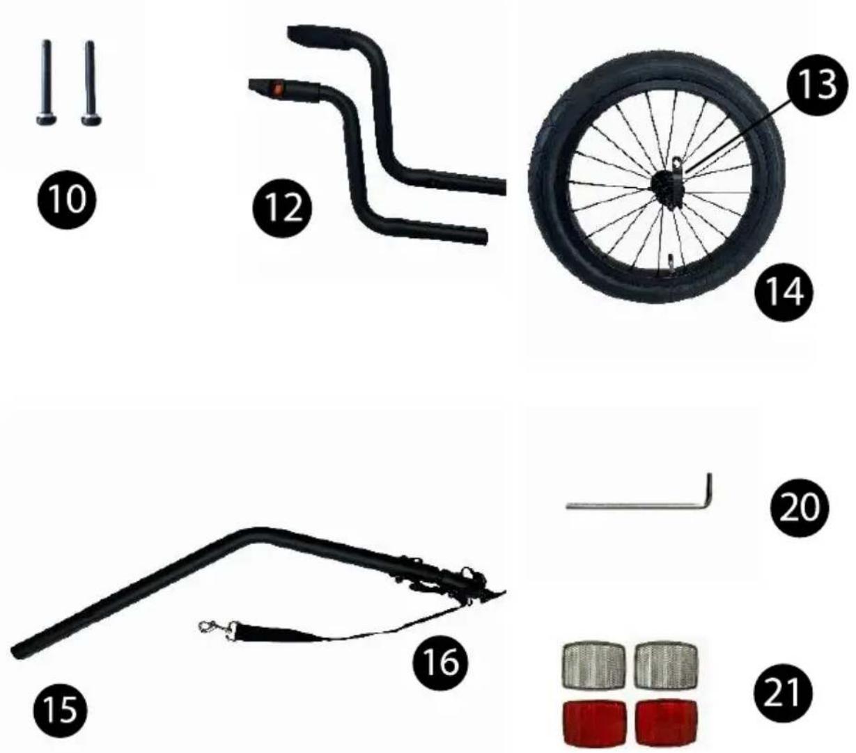

natural_image
Simple black-and-white illustration of a belt with a square end, labeled with the number 22 (no text or symbols on the belt itself)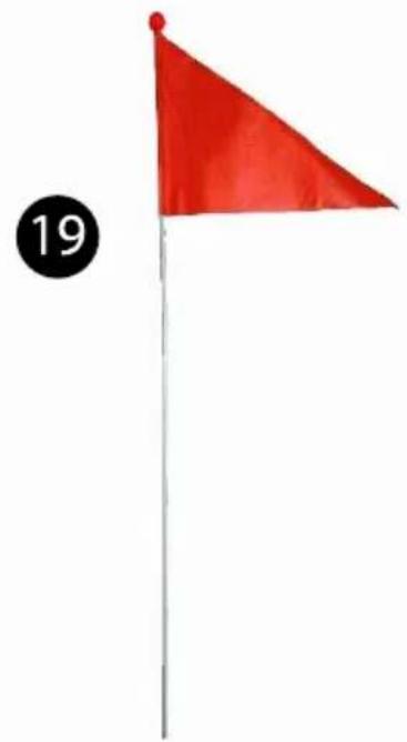
natural_image
Red flag on a pole with number 19 in the corner (no text or symbols on the flag itself)A
natural_image
Side view of a black and orange sports equipment vehicle (no visible text or symbols)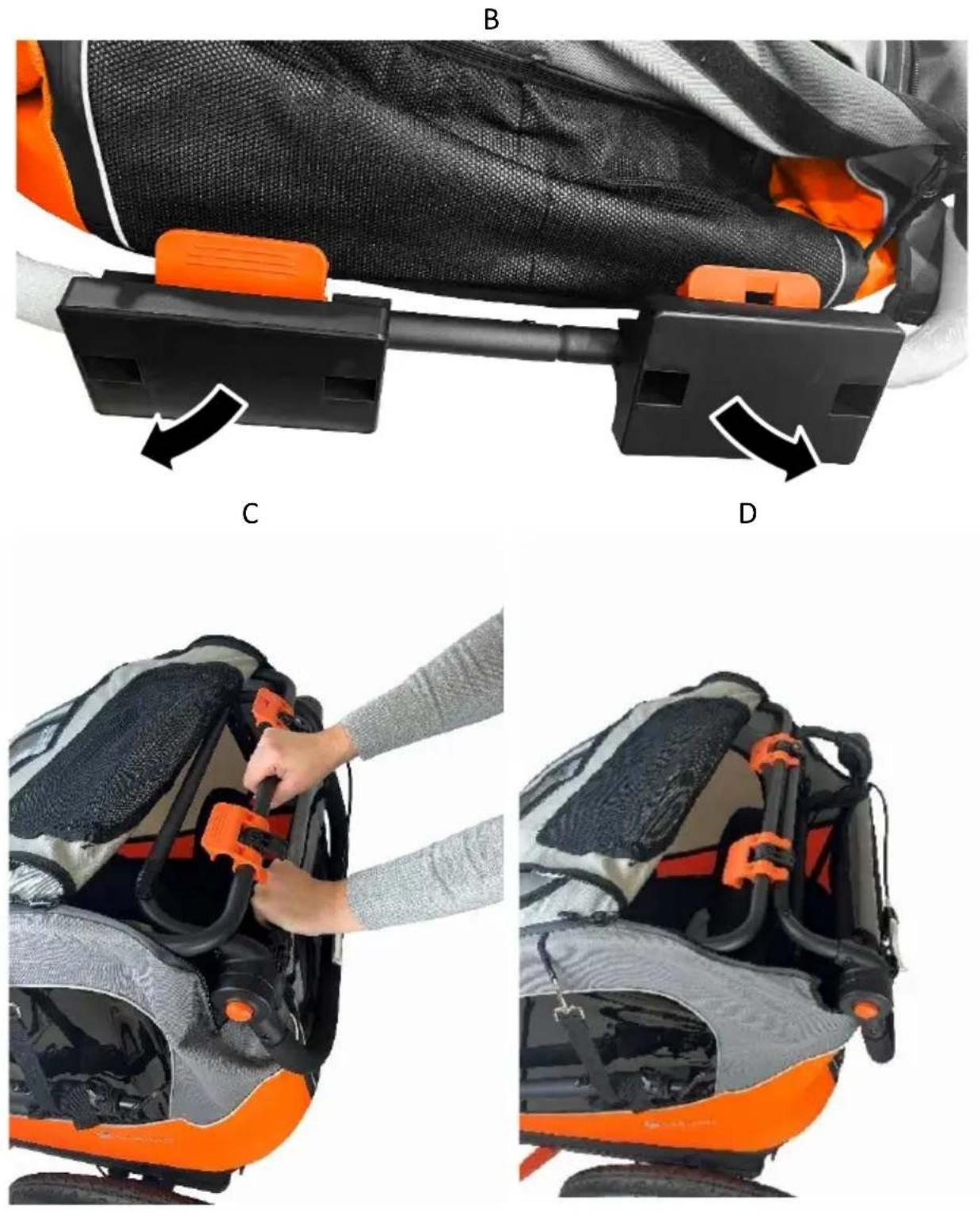
natural_image
Close-up of a motorcycle seat with orange safety clips and black mesh cover (no text or symbols visible)G
natural_image
Close-up of hands installing a black bicycle seat cover with orange and black stripes (no text or symbols visible)H
natural_image
Close-up of hands adjusting a black safety harness with orange straps and orange belt (no text or symbols visible)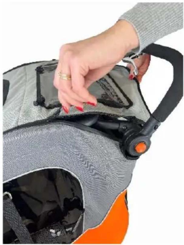
natural_image
Close-up of a hand adjusting a gray and black athletic helmet with orange accents (no text or symbols visible)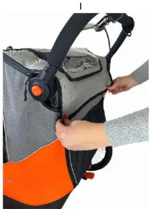
natural_image
Person adjusting a gray and black athletic vest with orange accents (no visible text or symbols)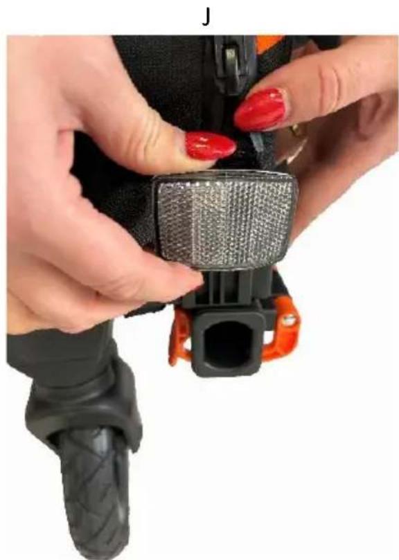
natural_image
Close-up of hands adjusting a black and orange seatbelt buckle with red nail polish (no text or symbols visible)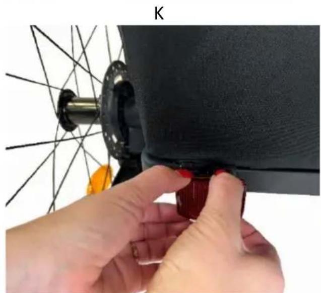
natural_image
Close-up of hands adjusting a red component on a bicycle wheel (no text or symbols visible)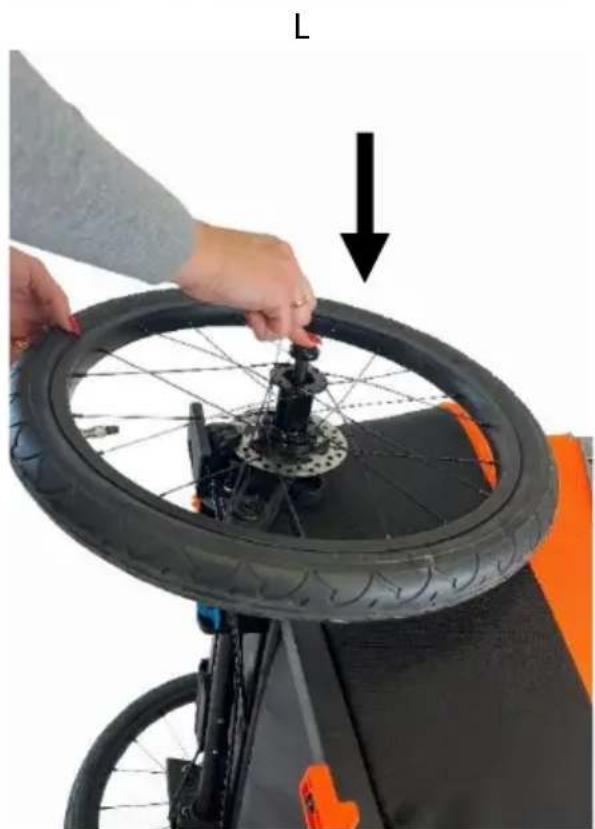
natural_image
Person adjusting a bicycle tire with a hand adjusting the wheel (no text or symbols visible)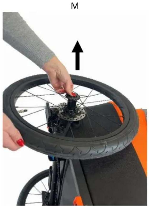
natural_image
Person assembling a bicycle tire with a hand adjusting the wheel (no text or symbols visible)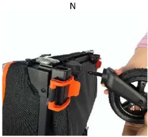
natural_image
Close-up of a hand using a black tool to adjust or install a black device component, with orange clamps and a small tire nearby (no text or symbols visible)0
text_image
PRESSP
natural_image
Close-up of a hand holding a black tool handle attached to a bicycle chassis (no visible text or symbols)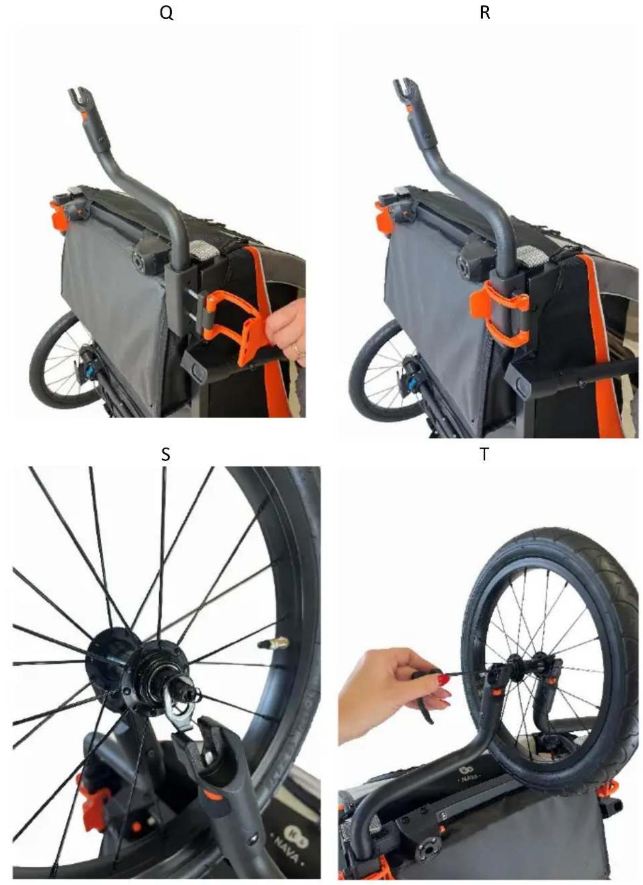
natural_image
Close-up of a bicycle wheel assembly with black frame and orange accent sensors (no text or symbols visible)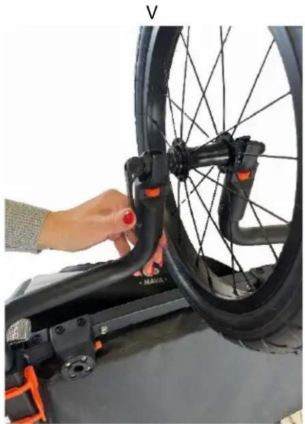
natural_image
Close-up of a hand adjusting a bicycle tire with orange accents, no visible text or symbols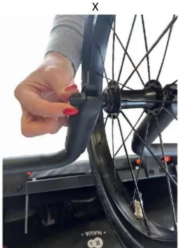
natural_image
Close-up of a hand adjusting a bicycle wheel rim, no visible text or symbols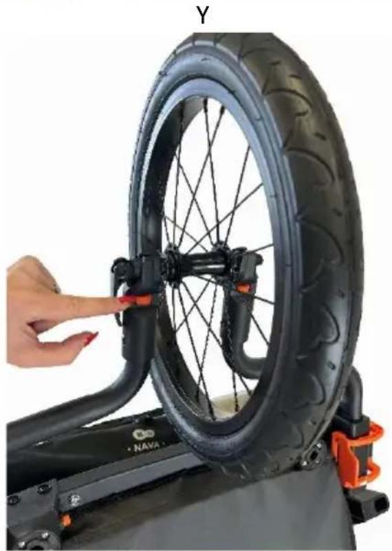
natural_image
Close-up of a bicycle tire being adjusted by a hand, no visible text or symbols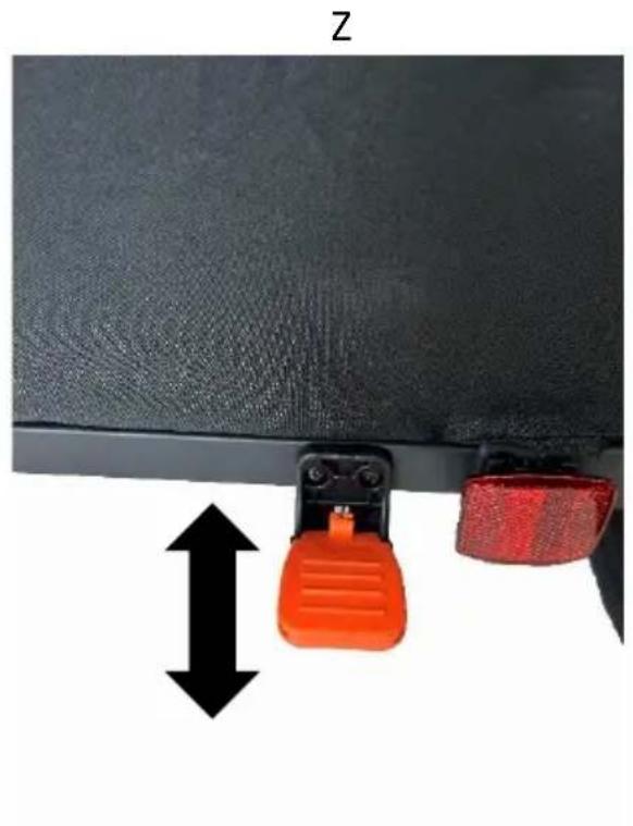
natural_image
Close-up of a black leather surface with orange and red plastic clips attached to a clip, showing a vertical double-headed arrow (no text or symbols)AB
natural_image
Close-up of a bicycle wheel with visible mechanical components and a blue directional arrow indicating motion (no text or symbols)AC
natural_image
Close-up of a hand adjusting a car seatbelt with orange clipers (no visible text or symbols)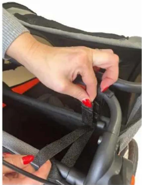
natural_image
Close-up of hands adjusting a black car seatbelt with red clips (no text or symbols visible)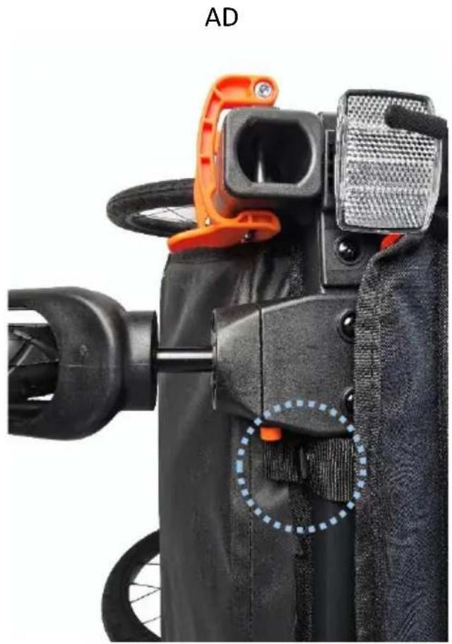
natural_image
Close-up of a black athletic device with orange clamping bracket and dotted circular annotation highlighting a specific part (no text or symbols)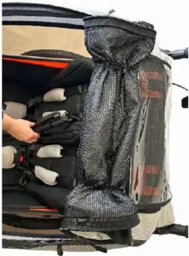
natural_image
Interior view of a car seatbelt with a person adjusting the seat, showing no visible text or symbols.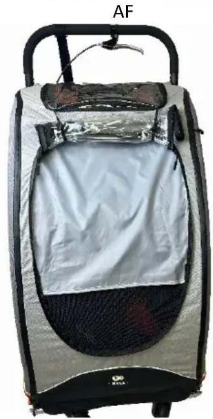
natural_image
Exterior view of a car clutch with silver mesh back cover and black handle (no text or symbols visible)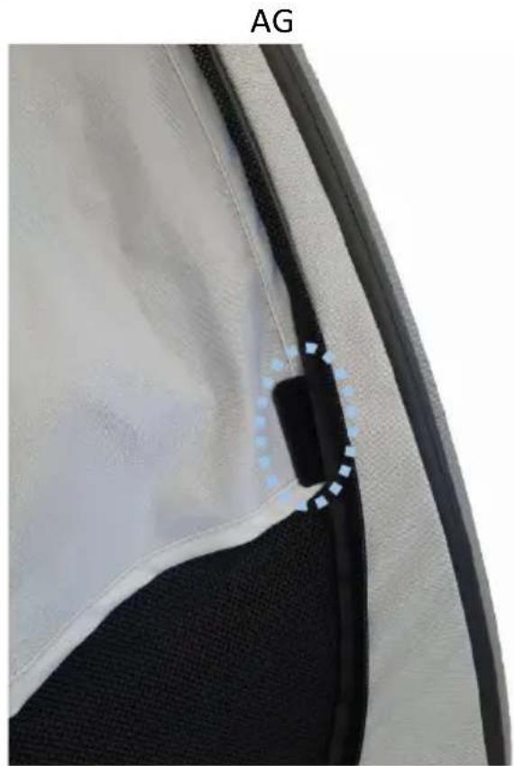
natural_image
Close-up of a car interior panel with a black plastic clip and blue dotted line marking (no text or symbols)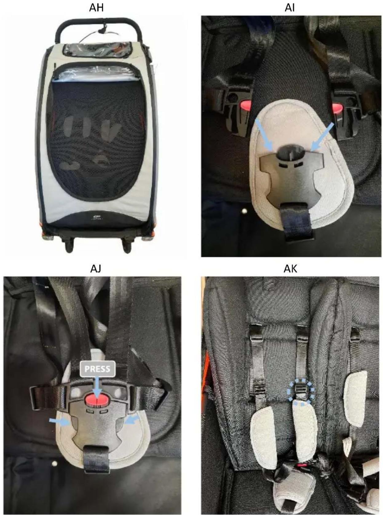
natural_image
Close-up of a mechanical clamp securing a black metal bracket with a screw, no visible text or symbols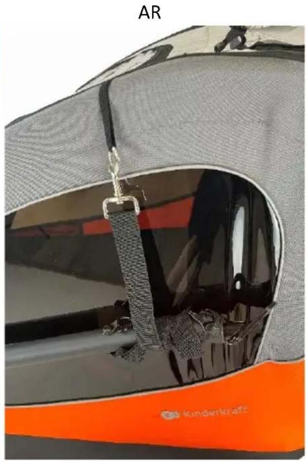
natural_image
Close-up of a car's seatbelt with orange and gray material, showing interior opening and visible seams (no text or symbols)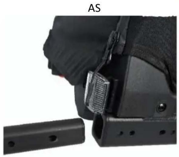
natural_image
Close-up of a black tactical vest with a visible grip and mounting bracket, labeled 'AS' (no text or symbols on the device itself)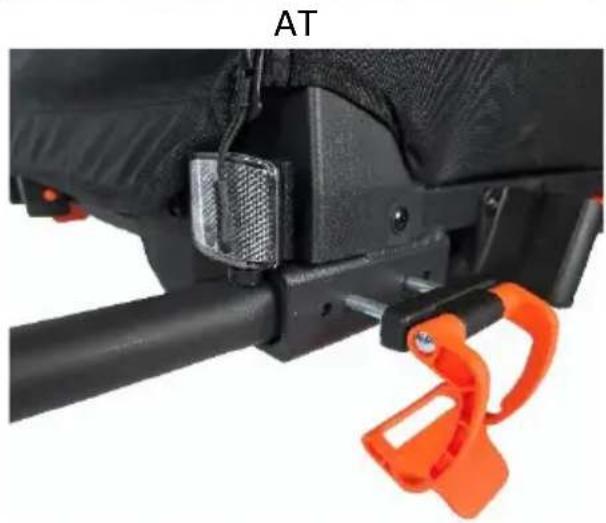
natural_image
Close-up of a black athletic device with orange and black clamps attached, labeled 'AT' (no readable text or symbols beyond label)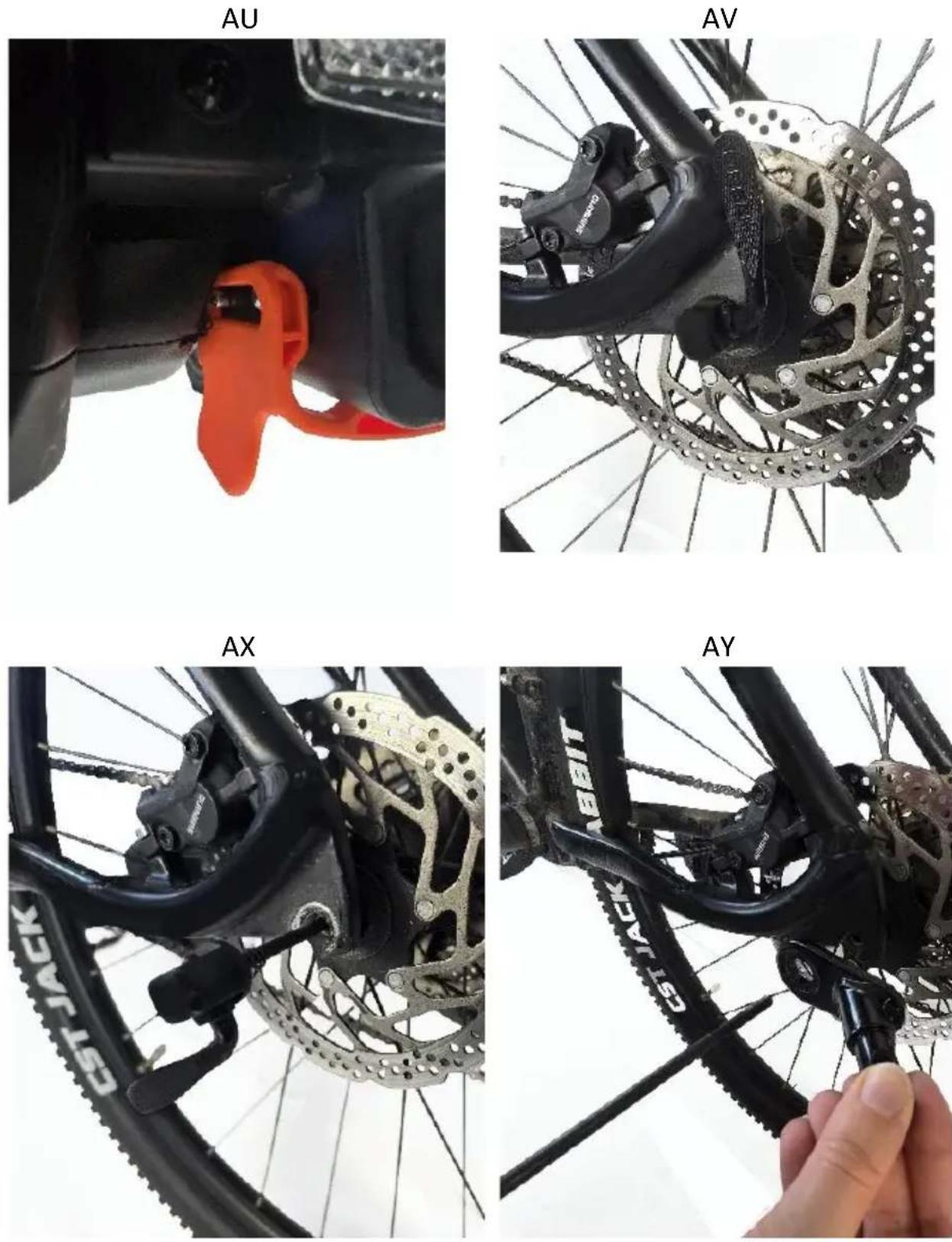
natural_image
Close-up of a bicycle's front wheel and rear wheel, showing mechanical components and tire marking (no text or symbols)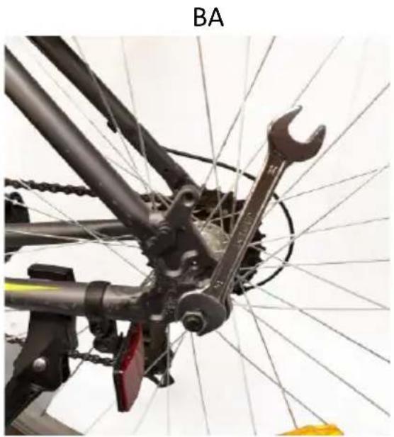
natural_image
Close-up of a bicycle's wheel and bicycle frame with a wrench tool (no text or symbols visible)BC
BB
natural_image
Close-up of a hand adjusting a bicycle wheel component with a metallic fitting (no text or symbols visible)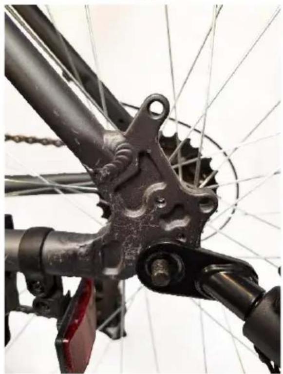
natural_image
Close-up of a bicycle's front wheel and suspension mechanism (no text or symbols visible)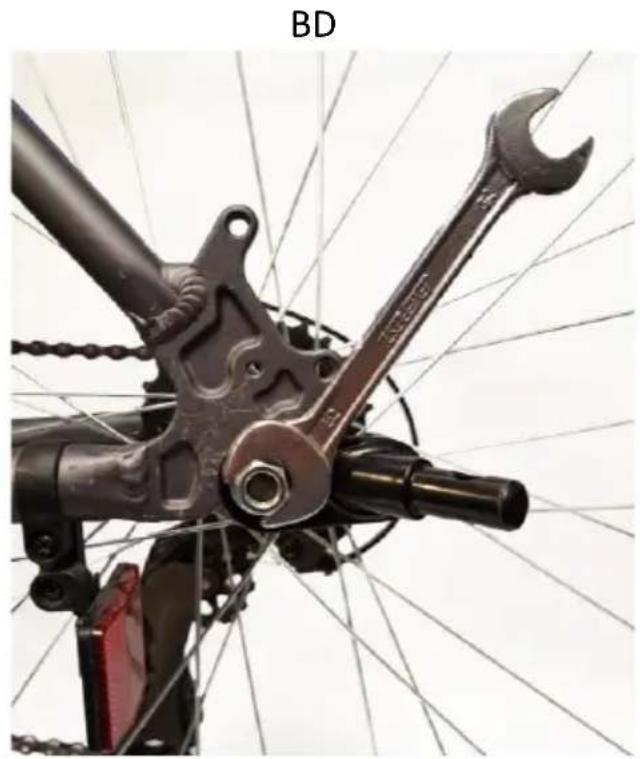
natural_image
Close-up of a bicycle's wheel and mechanical components, including a wrench and chain, with no visible text or symbols.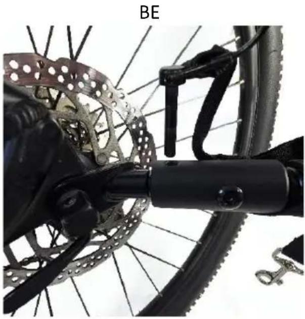
natural_image
Close-up of a bicycle's front wheel and chain assembly, showing gear and brake mechanism (no text or symbols)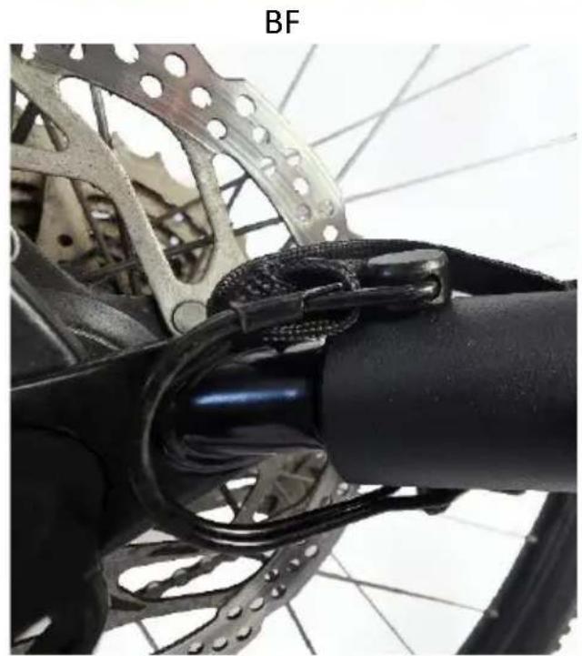
natural_image
Close-up of a bicycle's front wheel and suspension system, showing mechanical components and wiring (no text or symbols visible)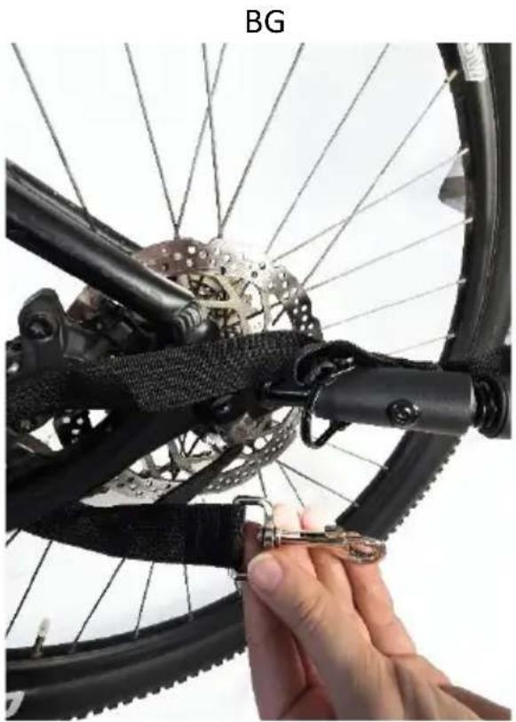
natural_image
Close-up of a hand adjusting a bicycle wheel with a key inserted, showing mechanical components and no visible text or symbols.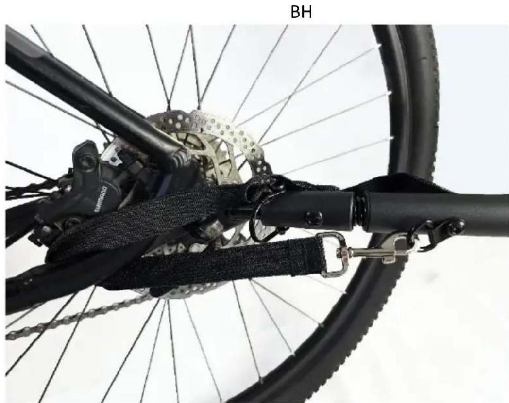
natural_image
Close-up of a bicycle's front wheel and rear suspension system, showing mechanical components and no visible text or symbols.BI
BJ
natural_image
Side profile of a gray and orange delivery scooter with wheels and a blue dotted circular indicator (no text or symbols visible)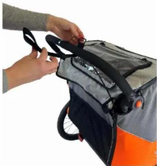
natural_image
Close-up of hands adjusting a gray and black shipping bag with orange and black stripes (no visible text or symbols)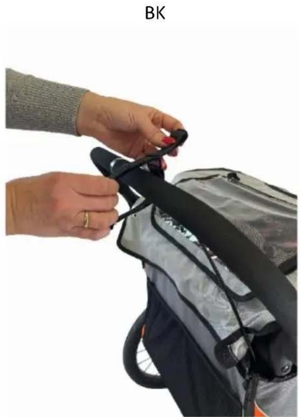
natural_image
Person adjusting a black strap on a silver bicycle (no text or symbols visible)BM
natural_image
Close-up of hands adjusting a black belt buckle on a silver athletic jacket (no text or symbols visible)BN
natural_image
Close-up of a hand adjusting a black and orange cable inside a car cab (no visible text or symbols)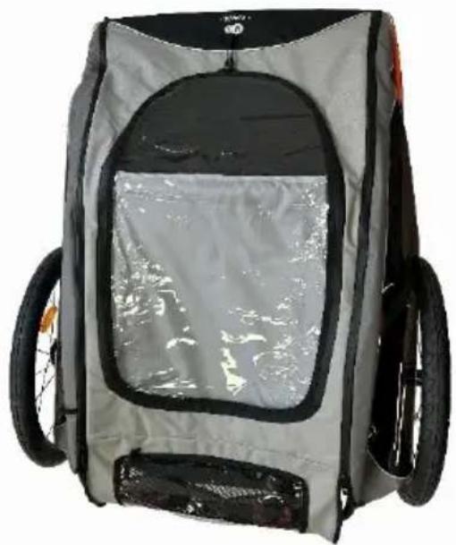
natural_image
Exterior view of a gray and black children's backpack with visible frame and wheels (no text or symbols)AR
عملانا الأعزاء!
Thank you for purchasing a Kinderkraft product. Our products are designed with your child's safety and comfort in mind. The stroller is an ideal solution for those who value quality, modernity and functionality. Please read the content of the user manual and follow its recommendations.
IMPORTANT - READ CAREFULLY AND KEEP FOR FUTURE REFERENCE. WARNING!
• Never leave the child unattended.
• Ensure that all the locking devices are engaged before use.
- To avoid injury ensure that the child is kept away when unfolding and folding this product.
• Do not let the child play with this product.
• Always use the restraint system.
- Check that the pram body or seat unit or car seat attachment devices are correctly engaged before use.
• The brakes should be locked when putting the baby in and out.
• Extreme caution should be used when folding or unfolding the product to avoid pinching fingers.
• It is not allowed to slide the stroller down stairs and escalators.
• The maximum load of the luggage compartment is 4 kg.
• The maximum load of the two internal side pockets is 0.5 kg each.
• The maximum load of the two rear mesh pockets is 0.5 kg each
• Do not place the product near open flames or other sources of heat.
• Only use parts and accessories that are supplied or recommended by the manufacturer. Do not use other parts and accessories.
• Please stop using the stroller if you have any doubts about the correct use or if you suspect any danger.
• Do not use the stroller if any components are damaged, cracked.
• The general condition of the product should be checked each time.
Applies to the stroller: WARNING!
• This product is not suitable for running or skating.
• This seat unit is not suitable for children under 6 months.
• The product is intended for children with weight/age: from 6 months to 22 kg or up to 4 years, whichever comes first.
• The product is designed to transport up to two children at a time.
• Do not hang any bag on the parent's handle.
- Any additional load, suspended on the handles of the wheelchair and/or behind the backrest and/or on the sides, causes a deterioration in its stability
- When driving up a curb or other step, raise the front suspension.
• Do not use with an additional platform.
Applies to the trailer:
 |  |
MAX 22 kg MAX 6 kg | MAX 42.5 kg |
MAX 45.5 kg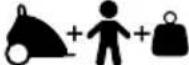 | MAX 60 kg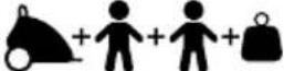 |
 |  |
 |  |


WARNING!
- Regularly check all important components such as the drawbar, connector, frame, seat belts, lighting, tires and wheels, etc. for safety.
• Regularly check the screw connections to ensure they are securely tightened. - Children should wear appropriate safety helmets while riding. Remark! In some countries, wearing a helmet is a legal requirement.
• Please note that the included trailer affects the braking time of the bike.
• Do not allow any part of the child's body, clothing, shoelaces or toys to come into contact with the moving parts of the trailer.
• Before using the product on public roads, check the local laws regarding where and how to use it.
• You must also comply with local legal requirements for lighting.
• Use caution when making turns. When manoeuvring, make sure that the drawbar of the trailer does not hit the bike frame.
• The front cover (flap) must always be closed when driving.
• Always use a warning flag when driving.
• The trailer must not be used in difficult terrain.
• Be sure to use proper caution when driving on hills.
• A trailer towed with an electric powered bicycle (EPAC) may be subject to legal restrictions.
• Remember to adapt your child's clothing to the temperature and weather outside
• The stated maximum load must not be exceeded.
• Always use caution and common sense when driving.
• Failure to follow these warnings and assembly instructions could result in serious personal injury or death!
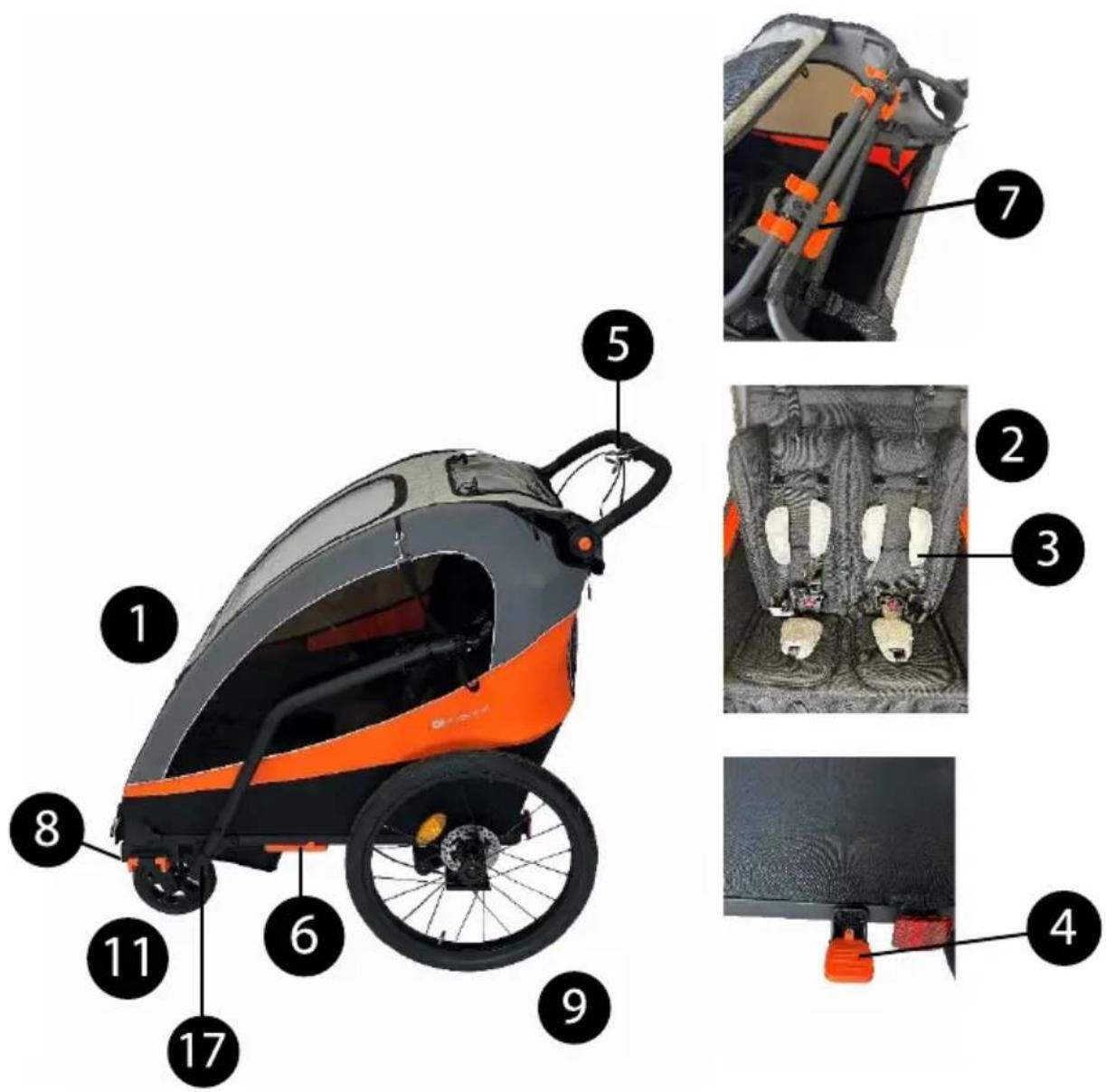
I. TROLLEY COMPONENTS (FIG. 1)
- Main frame with seat (2) with seat belts (3), foot brake (4) and handbrake (5), wheel guard (6)
top buckle (7) x2 and fastening clips (8) x2
- Rear wheels with reflectors
- Push-button wheel axle
- Front wheels for the "stroller" version
- Wheel mounting arms for the large wheel version
- Quick-release axle
- Large front wheel
- Drawbar with drawbar connector (16)
- Drawbar mounting and storage bracket with screws (18)
- Warning flag
- Allen wrenches for adjusting the brake shoes
- Reflectors: White x2, Red x2
- Security strap
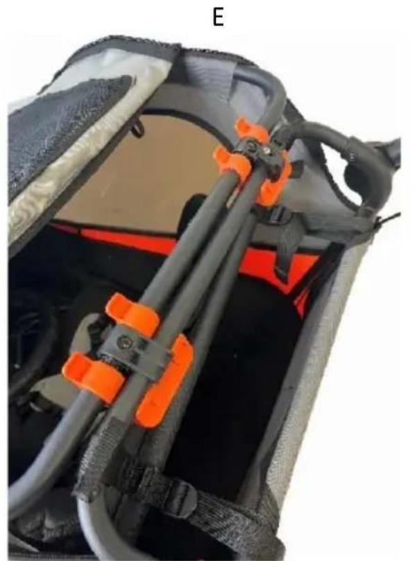
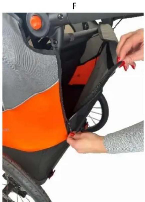
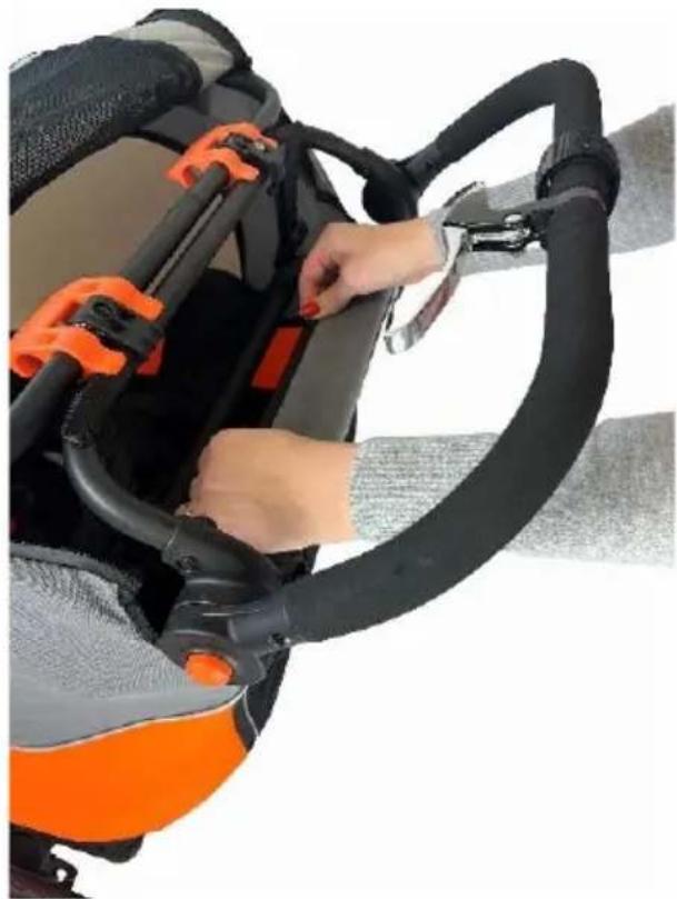
II. FRAME ASSEMBLY
The frame should be placed on a flat surface with the sheathing facing upwards (PIC. A). Dismantle the safety mechanism on the clamps: hold the frame with one hand and use the other hand to detach the safety from the clamp (PIC. B). Lift the part of the frame on which the buckles are mounted (7), then reach inside the stroller and pull up the handle inside it (PIC. C). Put the part of the frame to which the handle is attached, under the part on which the buckles are mounted, until it hooks on the black tabs located at the buckles (PIC. D). Twist both buckles until they snap into place (PIC. E). Press the buttons on both sides of the handle and lift it to a horizontal position. Fasten the zippers on the back of the flap (PIC. F), then pull it over and attach it to the frame with Velcro (PIC. G). Put the top flap on the frame and also secure it with zippers (PIC. H). Stretch the material of the upper flap and attach it with Velcro to the material of the lower flap (PIC. I). Place the white reflectors in the designated areas on the front of the stroller (PIC. J) and red reflectors in designated places at the back of the stroller (PIC. K).
III. MOUNTING AND DISMOUNTING WHEELS
REMARK! The truck is equipped with inflatable wheels: do not exceed the maximum permissible inflation pressure of the wheels - the value is given on the wheel tire.
REMARK! Never exceed the maximum pressure indicated on the sidewall of the tire, as over-inflation can lead to damage to the wheel and/or tire, posing a risk of serious injury. We recommend that you use pressures below the maximum permissible value, adapting them to the type of road surface and your preference in terms of driving comfort.
IMPORTANT: Do not use the air compressor to inflate tires. Use only the hand pump. Regularly take care of the condition of the wheels. Check the tire pressure with a suitable gauge before each use.
Rear Wheels (9):
Put the push-button wheel axle (10) through the rear wheel hub (9). By pressing the button on the push-button wheel axle, insert it completely through the rear wheel hub and insert the wheel into the hole provided for this purpose (FIG. L). To make sure the wheel is properly attached, pull it in your direction and check that it does not separate from the disc. To remove the rear wheel, press the button in the middle of the wheel and, while still pressing, pull the wheel towards you (PIC. M).
Front wheels:
1) Stroller version
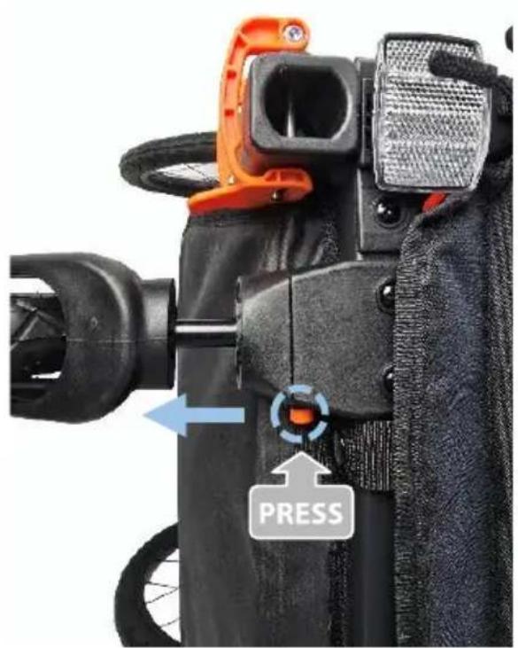
Slide the front wheels (11) into the holes provided for them (PIC. N) until you hear a lock sound. To remove the wheels, press the release button above each wheel and pull them out (PIC. O).
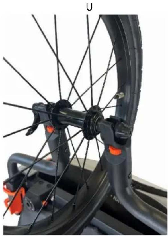
2) Big wheel version
If the trailer has a drawbar or wheels for the stroller version, you must first disassemble these elements. The kit for the big wheel version consists of two spokes (12) and a large wheel (14). Lift the front of the trailer, unclip the fastening clips on both sides and remove them. Slide the front wheel arms into the mounting slots with the adjustment rings facing down (PIC. P) and secure them to the frame using the retaining clips removed earlier (FIG. Q) – insert the pins into the holes and lock the fastening clips until you hear a click (PIC. R). Place a lock washer on the axle (FIG. S), then put the quick-release axle (13) through the hole in the wheel (FIG. T) and secure it on the other side with a nut. Place the wheel prepared in this way in the arms of the front wheel (PIC. U). Then tighten the wasp nut (PIC. X) and close the quick-release lever (FIG. V). Check that the wheel and side arms are securely fixed by pulling on them. If the stroller is not going exactly straight ahead in a large-wheel configuration, the trajectory can be adjusted by turning the adjustment rings on the front wheel arms (FIG. Y).
REMARK! The opening and closing of the clamp is not smooth and requires a certain amount of force. This is necessary to ensure that the clamp is held securely.
REMARK! The large wheel and side arms must be properly fastened after assembly. Driving with an incorrectly fastened set can lead to accidents with life-threatening injuries. If in doubt, contact a specialist repairer.
REMARK! Before using the stroller, make sure that all wheels are properly fitted.
IV. USING THE BRAKES
1) Foot parking brake
The trolley is equipped with a foot parking brake (4), located at the rear on the frame frame. Push the brake down; When you hear the lock sound, the brake is activated. Unlocking takes place after lifting the brake up (PIC. Z).
The handbrake disc brake (5) is located on the handle of the stroller. It is used to reduce speed while walking.
BRAKE ADJUSTMENT
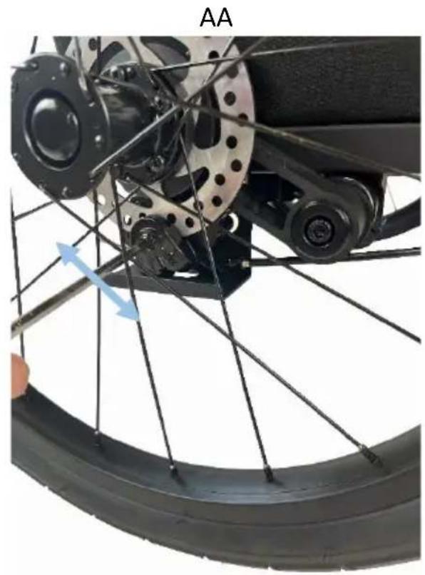
Use a 5mm Allen wrench (20) to adjust the brake shoes. Turning the wrench counterclockwise will loosen the brake shoes, which will reduce braking performance. Turning the wrench clockwise (clockwise) will tighten the brake shoes, which will increase braking performance (FIG. AA).
REMARK! When adjusting, the brake pads should be as close to the brake discs as possible. The brake pads should not rub loudly or squeak – only gentle rubbing against the brake discs is acceptable. Always check the operation of the wheels after adjustment.
V. BACKREST ADJUSTMENT
The seat has a smooth backrest adjustment from a straight to a slightly tilted position using the backrest adjustment straps located under the top flap on both sides. To incline the backrest, extend the straps attached to the frame next to the buckles by tilting the adjuster (PIC. AB) to unlock the strap. To return the backrest to the upright position, pull the straps upwards until the desired position is reached (PIC. AC).
VI. FRONT COVER (FLAP)
The lid has a protective function, insulating the interior from adverse weather conditions, such as rain or wind. Thanks to this, children are protected from getting wet and chilled while traveling. The front flap consists of a window with a rain cover, sun visor and mosquito net. In order to lift the front flap completely, first unfasten the press studs, which are located on the bottom of the frame near the front wheel release buttons (FIG. AD). Then you need to unzip the zippers on both sides of the flap as much as possible, roll it up and secure it with an elastic band inside the stroller at the top of the flap and buttons located at the viewing window (PIC. AE). It is possible to detach the rain cover itself – to do this, unzip the zippers around it, roll it inwards and place it inside the flap (PIC. AF). To raise the sun blende, unfasten the Velcro fasteners at its base on both sides (PIC. AG), roll it up and place it inside the hatch (FIG. AH).
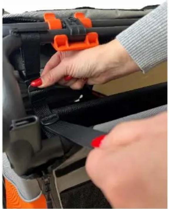
VII. SEAT BELTS
To secure the child, insert the shoulder and lap belt buckles into the middle buckle until the lock is in place (PIC. AI). To unfasten the belts, press the red buttons in the middle of the buckle with one hand and press the black side buttons with the other hand (PIC. AJ). The seat belts can be adjusted to the child's height using adjustment straps and adjusters (PIC. AK). Remember to keep the belts at an appropriate distance from the child's body. Belts that are too loosely adjusted may not hold the child properly, which can lead to life-threatening injuries in the event of an accident. Belts that are too tightly adjusted can dig into the child's body, which can lead to discomfort while driving.
REMARK! Always use a fastening system. The belts must be adjusted each time.
VIII. SUSPENSION HARDNESS ADJUSTMENT
There are two rear wheel suspension positions:
Position No. 1: designed for a maximum load of 22 kg.
Position No. 2: designed for a maximum load of >22 kg.
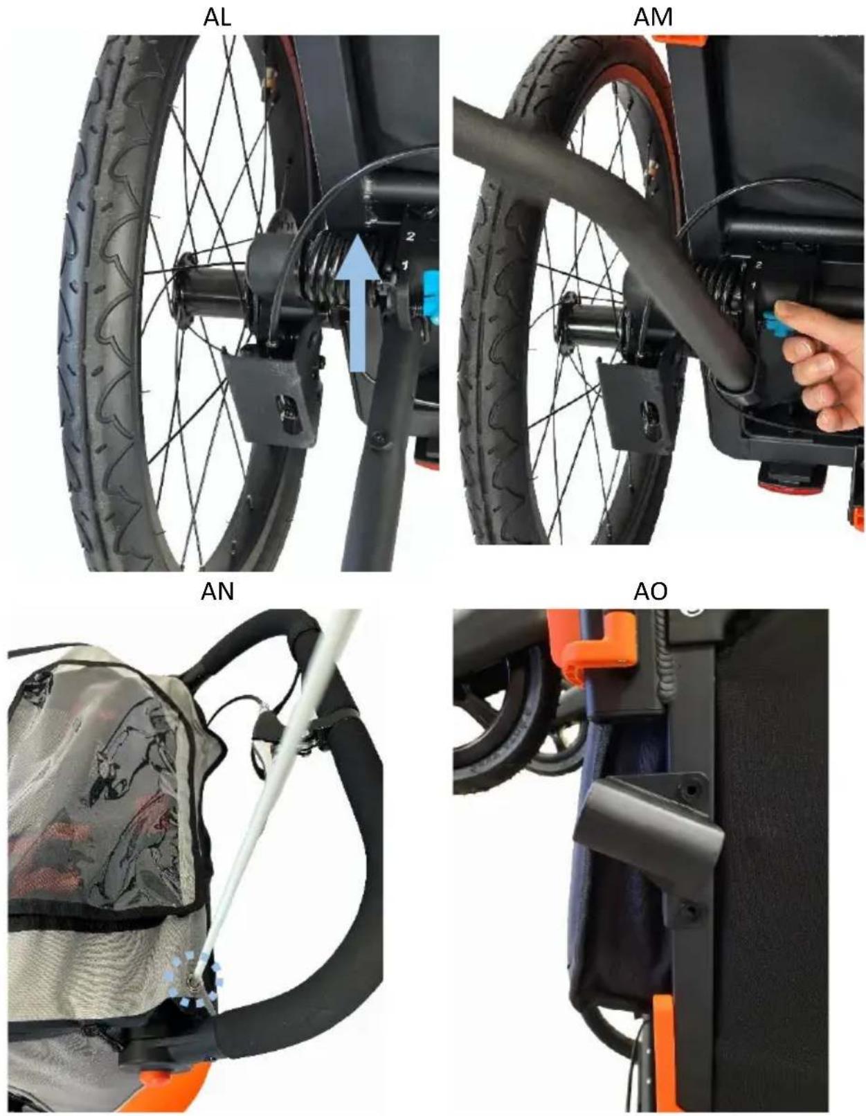
The trailer is factory set to position No. 1. If you plan to carry a load exceeding 22 kg, use the drawbar and raise the suspension to position 2. To do this, tilt the trailer so that the entire chassis is visible. Insert the drawbar into the hole under the adjustment button and lift it until you hear a click (FIG.AL). To return the mechanism to position no. 1, insert the drawbar into the hole, lift it up slightly, then press the button used to adjust the suspension and guide the drawbar downwards (FIG. AM). With each adjustment, remember to perform the operation from both sides.
IX. INSTALLATION OF THE FLAG
To increase the visibility of the bicycle trailer to other road users, always use the warning flag (19) supplied. This increases your safety and the safety of your child. The safety flag should be put through the hole on the left side of the flap and placed in the tunnel located there (PIC. AN).
REMARK! The safety flag must always be attached when the trolley is in trailer configuration. Not having a pennant can make your bike trailer less visible in traffic, which can lead to life-threatening accidents.
REMARK! Before folding the trailer, remove the safety flag. Otherwise, the flagpole may break.
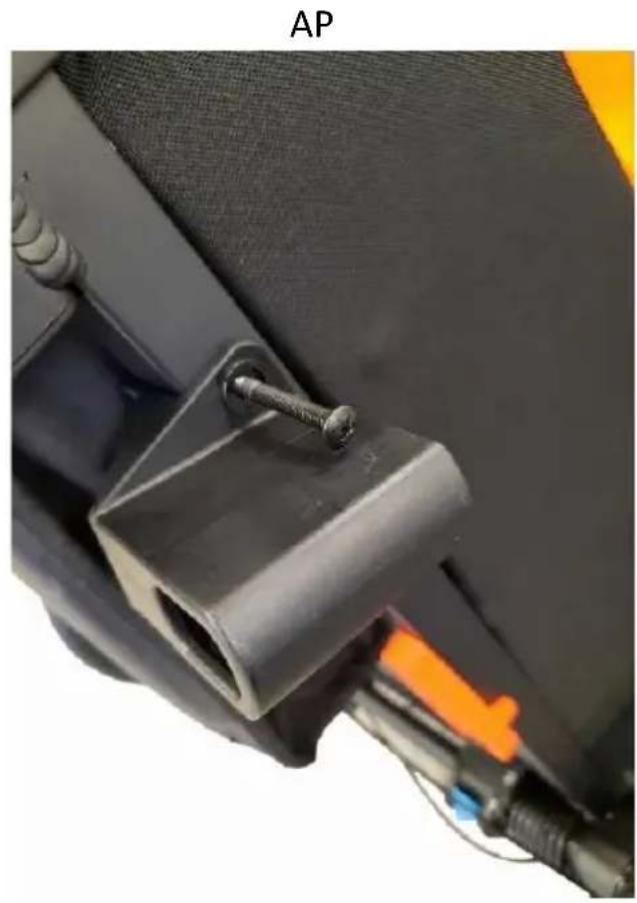
X. MOUNTING THE DRAWBAR STORAGE BRACKET
Start by pushing the footrest inwards of the stroller to expose the part of the frame where the handle will be mounted. Attach the mount to the frame at the location shown in the AO photo, then insert the nuts into the holes provided for this purpose in the holder. Place the screws in the holes (PIC. AP) and screw them in place with a Phillips screwdriver. Make sure the screws are tightly tightened and the mount is firmly attached to the frame. Place the drawbar in the holder, wrap the strap on the drawbar head around it twice, and hook the spring carabiner onto the elastic band attached to the sheathing (PIC. AR). To disassemble the drawbar storage bracket, perform the above steps in reverse order.
XI. DRAWBAR ATTACHMENT
Release the retaining clip located under the front white reflector on the right side and remove it from the frame. Insert the drawbar into the hole in the frame (FIG. AS) and then secure it with the fastening clip: insert the two steel pins into the holes on the side of the bicycle trailer (FIG. AT) and close the clip. The clamp is securely closed only if you hear a loud click (PIC. AU). When using the trailer, the two steel pins must always be locked in place with a clamp. The drawbar must always be mounted on the right side of the bicycle trailer - it must not be mounted on the left side.
REMARK! Before use, make sure that the drawbar is securely fastened so that no serious accidents and injuries
occur.
XII. CONNECTION TO THE BICYCLE
REMARK! Before attaching the trailer to the bike, check whether the towing bike is approved by the manufacturer for towing trailers in the bike manual.
REMARK! Towing trailers with an unsuitable bike can lead to frame breakage and life-threatening accidents.
REMARK! Installation of the trailer should always be done without a child in the caravan.
1). Installation of drawbar connector on the rear wheel of the bike:
Quick release:
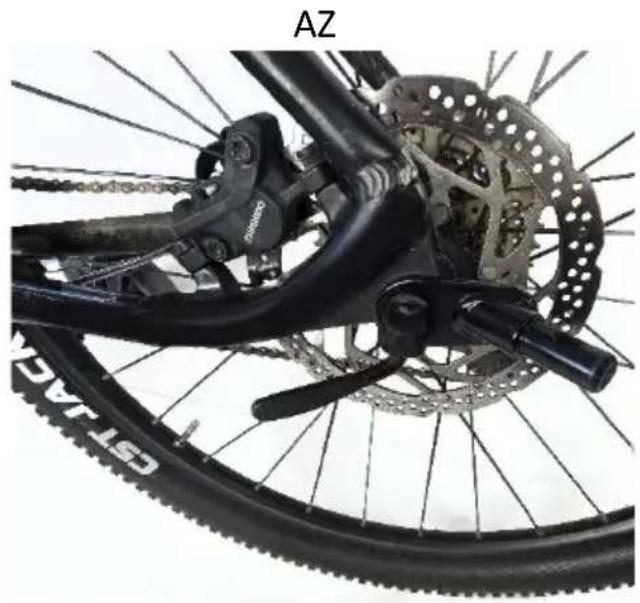
The connector should always be mounted on the left side of the bicycle wheel (when viewed in the direction of travel). To properly connect the trailer to your bike, follow these steps: first, open the quick-release lever (PIC. AV) that is located on the axle of the bike, then unscrew the axle nut by turning counterclockwise. Be careful as there is a small spring under the nut that can slip out. Extend the axis all the way out (FIG. AX), put the drawbar connector on it and put it back in (FIG. AY). Tighten the nut, align the rear wheel, and close the quick-release lever (PIC. AZ). In the final phase, just before reaching the closed position, the lever should offer a clear resistance. In its final position, the connector must be parallel to the frame and must not protrude beyond its outline. Make sure the quick release is properly locked in place when trying to rotate it around its axis. If the closed quick-release can be turned, the clamping force is insufficient. In this case, open the lever and tighten the axle nut by half a turn clockwise. If the lever cannot be fully closed, reopen it and loosen the axle nut by half a turn, turning counterclockwise.
REMARK! Be sure to keep the axle nut screwed onto the quick-release thread according to the instructions of the bike you are using.
Fixed axis:
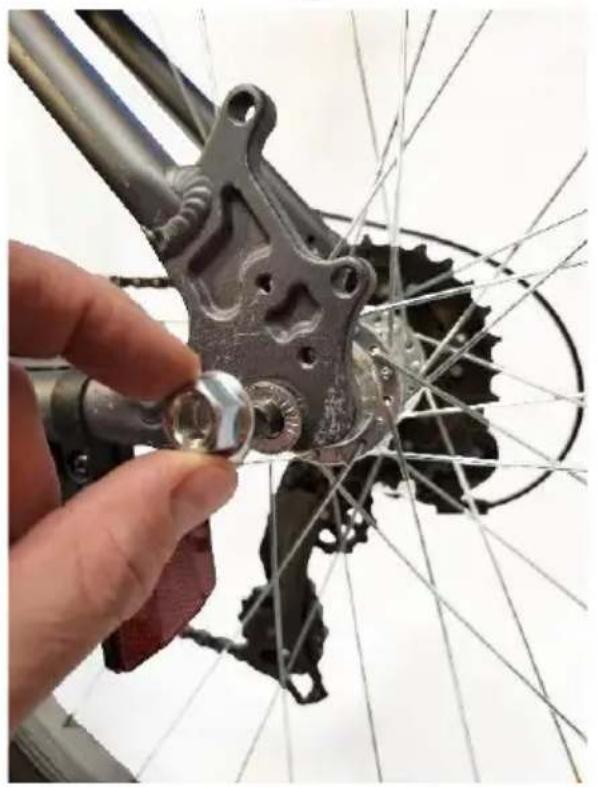
The connector should always be mounted on the left side of the bicycle wheel (when viewed in the direction of travel). Use a wrench to unscrew the axle nut on the left side of the rear wheel by turning it counterclockwise (FIG. BA). Remove the lock washer (FIG. BB), install the drawbar coupler (PIC. BC) and secure it with the previously removed washer (PIC. BD. Adjust the rear wheel to the correct position so that it is straight, then tighten the axle nut with the force (torque) indicated in the towing bike's manual. When tightening, hold the axle steady to prevent the wheel from changing position.
REMARK! Follow the owner's manual for your towing bike. If in doubt, consult a specialist workshop.
2). Connection of the coupler with the drawbar
Lift the drawbar and slide the drawbar head over the connector mounted on the rear wheel hub axle of the bike. Place the pin in the hole located in the drawbar head (FIG. BE), and then secure it with a cotter pin (PIC. BF). Make sure the connection is secure by pulling on the drawbar. Then pass the safety strap around the bike frame tube (PIC. BG) and hook the carabiner in the handle on the drawbar (PIC. BH). Make sure the seat belt does not catch on the spokes or disc brakes.
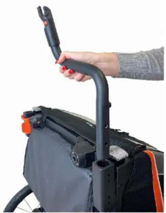
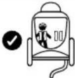
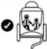
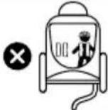
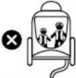
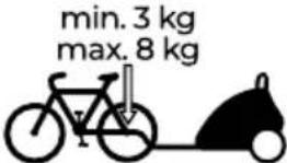
REMARK! When using the trailer, the handle must be in one of the positions shown in the graphic. Do not set other positions.
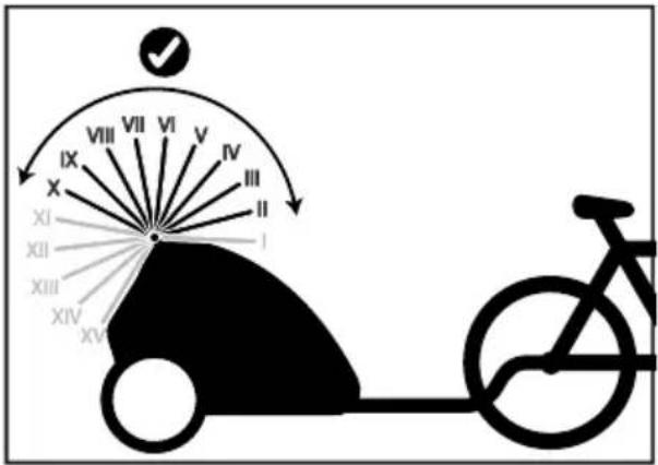
text_image
IX VIII VII VI V IV III II XI XII I XIII XIV XVREMARK! Make sure the coupler is properly secured in the drawbar head. If it is not properly attached, the trailer can detach while driving, which can lead to life-threatening accidents.
REMARK! Never drive without securing the drawbar with a seat belt! If the trailer detaches, it will remain connected to the bike. Failure to do so can lead to life-threatening accidents.
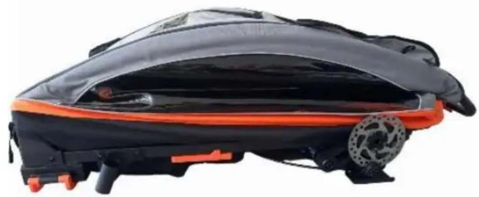
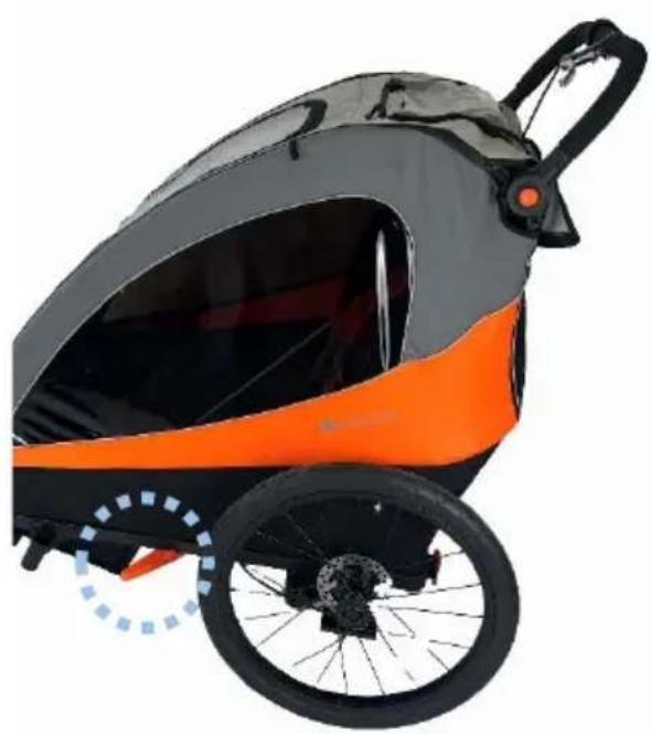
The wheel guard (6), which should be used in the trailer configuration, protects the wheels from collisions with obstacles (PIC. BI).
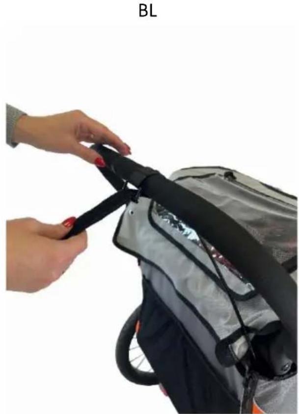
XIII. SAFETY STRAP
The stroller comes with a safety strap (22), which must be mounted on the handle. To do this, put the belt under the handle (PIC. BJ), put its end through a belt loop (PIC. BK) and stretch (PIC. BL). When the belt is not in use, wrap it around itself and secure it with Velcro before unwinding.
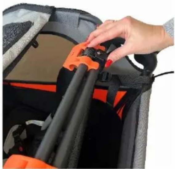
XIV. ASSEMBLING THE TROLLEY
Unhook the Velcro on the top flap, unzip the zippers on both sides and tilt the flap. Detach the Velcro on the back wall of the fabric and unzip the zippers as much as possible. Place the handle in the lowest position. To release the left buckle, press it down; repeat the operation with the right buckle after pressing the lock button (PIC. BM). Put the part of the frame on which the handle is located under the frame on which the buckles are attached and guide it to the inside of the stroller. Finally, lower the part of the frame with the buckles. A properly assembled frame is shown in the BN photo.
XV. CARE AND MAINTENANCE
It is the responsibility of the purchaser to ensure the correct installation of all functional components, as well as to carry out appropriate maintenance and adjustments in order to keep the truck in good working order. The stroller should be checked periodically for potential problems. The following are important steps to take to ensure the safety of your child and to prevent shortened product life:
- Check the strength and safety of any rivets and joints.
- Check all restraint devices and wheels and their tyres and replace or repair them if necessary.
- Check that all safety devices are working properly, with particular attention to the main and secondary fasteners, which should move freely at all times.
If the wheels squeak, lubricate the axles with a thin layer of silicone. Do not use oil- or grease-based products as they attract dirt that obstructs movement.
XVI. CLEANING

Wash at max. 30°C, gentle process.

Do not wash. The product can be washed gently with a damp cloth and a mild detergent.

Do not bleach

Do not iron

Do not tumble dry

Do not dry clean
If the chassis components of the trolley have been exposed to salt water, we recommend rinsing them off with fresh water (from the tap) as soon as possible.
Seat cover, housing, flaps, seat belt - Do not wash. The product can be washed gently with a damp cloth and a mild detergent. Do not tumble dry. Do not dry clean. Do not iron. Do not bleach.
Do not fold or store the product when wet and never store it in humid conditions, as this may lead to the formation of mold.
XVII. Warranty
The full text of the Warranty Terms and Conditions is available on the website of WWW.KINDERKRAFT.COM
XII. CONECTAREA LA BICICLETĂ
text_image
IX XI XII XIII XIV XV XVI XVII XVIII XVIV XVIII XVIV XVIII XVIV XVIII XVII XVIII XVIV XVIII XVII XVIII XVIV XVIII XVII XVIII XVIV XVIII XVII XVIII XVIV XVIII XVII XVIII XVIV XVIII XVII XVIII XVIV XVIII XVII XVIIII XVIIIII XVIIIIIIIIIIIIIIIIIIIIIIIIIIIIIIIIIIIIIIIIIIIIIIIIIIIIIIIIIIIIIIIIIIIIIIIIIIIIIIIIIIIIIIIIIIIIIIIIIIIIIIIIIIIIIIIIIIIIIIIIIIIIIIIIIIIIIIIIIIIIIIIIIIIIIIIIIIIIIIIIIIIIIIIIIIIIIIIIIIIIIIIIIIIIIIIIIIIIIIII II II II II II II II II II II II II II II II II II II II II II II II II II II II II II II II II II II II II II II II II II II II II II II II II II II II II II II II II II II II II II II II II II II II II II II II II II II II II II II II II II II II II II II II II III III III III III III III III III III III III III III III III III III III III III III III III III III III III III III III III III III III III III III III III III III III III III III III III III III III III III III III III III III III III III III III III III III III III III III III III III III III III III III III III III III III III III III III III III III III III III III III III III III III IIIIII I XIXIXIXIXIXIXIXIXIXIXIXIXIXIXIXIXIXIXIXIXIXIXIXIXIXIXIXIXIXIXIXIXIXIXIXIXIXIXIXIXIXIXIXIXIXIXIXIXIXIXIXIXIXIXIXIXIXIXIXIXIXIXIXIXIXIXIXIXIXIXIXIXIXIXIXIXIXIXIXIXIXIXIXIXIXIXIXIXIXIXIXIXIXIXIXIXIXIXIXIXXXXXXXXXXXXXXXXXXXXXXXXXXXXXXXXXXXXXXXXXXXXXXXXXXXXXXXXXXXXXXXXXXXXXXXXXXXXXXXXXXXXXXXXXXXXXXXXXXXXXXXXXXXXXXXXXXXXXXXXXXXXXXXXXXXXXXXXXXXXXXXXXXXXXXXXXXXXXXXXXXXXXXXXXXXXXXXXXXXXXXXXXXXXXXXXXXXXXXXXXXXXXXXXXXXXXXXXXXXXXXXXXXXXXXXXXXXXXXXXXXXXXXXXXXXXXXXXXXXXXXXXXXXXXXXXXXXXXXXXXXXXXXXXXXXXXXXXXXXXXXXXXXXXXXXXXXXXXXXXXXXXXXXXXXXXXXXXXXXXXXXXXXXXXXXXXXXXXXXXXXXXXXXXXXXXXXXXXXXXXXXXXXXXXXXXXXXXXXXXXXXXXXXXXXXXXXXXXXXXXXXXXXXXXXXXXXXXXXXXXXXXXXXXXXXXXXXXXXXXXXXXXXXXXXXXXXXXXXXXXXXXXXXXXXXXXXXXXXXXXXXXXXXXXXXXXXXXXXXXXXXXXXXXXXXXXXXXXXXXXXXXXXXXXXXXXXXXXXXXXXXXXXXXXXXXXXXXXXXXXXXXXXXXXXXXXXXXXXXXXXXXXXXXXXXXXXXXXXXXXXXXXXXXXXXXXXXXXXXXXXXXXXXXXXXXXXXXXXXXXXXXXXXXXXXXXXXXXXXXXXXXXXXXXXXXXXXXXXXXXXXXXXXXXXXXXXXXXXXXXXXXXXXXXXXXXXXXXXXXXXXXXXXXXXXXXXXXXXXXXXXXXXXXXXXXXXXXXXXXXXXXXXXXXXXXXXXXXXXXXXXXXXXXXXXXXXXXXXXXXXXXXXXXXXXXXXXXXXXXXXXXXXXXXXXXXXXXXXXXXXXXXXXXXXXXXXXXXXXXXXXXXXXXXXXXXXXXXXXXXXXXXXXXXXXXXXXXXXXXXXXXXXXXXXXXXXXXXXXXXXXXXXXXXXXXXXXXXXXXXXXXXXXXXXXXXXXXXXXXXXXXXXXXXXXXXXXXXXXXXXXXXXXXXXXXXXXXXXXXXXXXXXXXXXXXXXXXXXXXXXXXXXXXXXXXXXXXXXXXXXXXXXXXXXXXXXXXXXXXXXXXXXXXXXXXXXXXXXXXXXXXXXXXXXXXXXXXXXXXXXXXXXXXXXXXXXXXXXXXXXXXXXXXXXXXXXXXXXXXXXXXXXXXXXXXXXXXXXXXXXXXXXXXXXXXXXXXXXXXXXXXXXXXXXXXXXXXXXXXXXXXXXXXXXXXXXXXXXXXXXXXXXXXXXXXXXXXXXXXXXXXXXXXXXXXXXXXXXXXXXXXXXXXXXXXXXXXXXXXXXXXXXXXXXXXXXXXXXXXXXXXXXXXXXXXXXXXXXXXXXXXXXXXXXXXXXXXXXXXXXXXXXXXXXXXXXXXXXXXXXXXXXXXXXXXXXXXXXXXXXXXXXXXXXXXXXXXXXXXXXXXXXXXXXXXXXXXXXXXXXXXXXXXXXXXXXXXXXXXXXXXXXXXXXXXXXXXXXXXXXXXXXXXXXXXXXXXXXXXXXXXXXXXXXXXXXXXXXXXXXXXXXXXXXXXXXXXXXXXXXXXXXXXXXXXXXXXXXXXXXXXXXXXXXXXXXXXXXXXXXXXXXXXXXX XXX XXX XXX XXX XXX XXX XXX XXX XXX XXX XXX XXX XXX XXX XXX XXX XXX XXX XXX XXX XXX XXX XXX XXX XXX XXX XXX XXX XXX XXX XXX XXX XXX XXX XXX XXX XXX XXX XXX XXX XXX XXX XXX XXX XXX XXX XXX XXX XXX XXX XXX XXX XXX XXX XXX XXX XXX XXX XXX XXX XXX XXX XXX XXX XXX XXX XXX XXX XXX XXX XXX XXX XXX XXX XXX XXX XXX XXX XXX XXX XXX XXX XXX XXX XXX XXX XXX XXX XXX XXX XXX XXX XXX XXX XXX XXX XXX XXX XXX XXX XXInternational contact:
support@kinderkraft.com
+44 20 4525 0748
متح/VÝROBCE/HERSTELLER/MANUFACTURER/FABRICANTE/FABRICANT/GYARTÓ/FABBRICANTE/FABRIKANT/PRODUCENT/FABRICANTE/PRODUCÁTOR/ПРОИЗВОДИТЕЛЬ/VÝROBCA/TILLVERKARE: