Plana 7.0 - Plane SCHEPPACH - Free user manual and instructions
Find the device manual for free Plana 7.0 SCHEPPACH in PDF.

User questions about Plana 7.0 SCHEPPACH
0 question about this device. Answer the ones you know or ask your own.
Ask a new question about this device
Download the instructions for your Plane in PDF format for free! Find your manual Plana 7.0 - SCHEPPACH and take your electronic device back in hand. On this page are published all the documents necessary for the use of your device. Plana 7.0 by SCHEPPACH.
USER MANUAL Plana 7.0 SCHEPPACH
natural_image
Scheppach Plana 7.0 machine with blue and white casing, no visible text or symbols on the machine itself.Hersteller:
Günzburger Straße 69
0-89335 Ichenhausen / BRD
Verehrter Kunde,
natural_image
Hand holding a tool interacting with a mechanical component (no visible text or symbols)Abb.: „B“
natural_image
Close-up of a mechanical assembly with a numbered component (1) and directional arrows, no readable text or symbols present.Abb. „C“
Abrichtanschlag
Abb.:,B"
natural_image
Hand operating a machine with a handle, showing blade and frame structure (no text or symbols visible)Abb. „E“
natural_image
Person adjusting a mechanical device with a clamping tool (no visible text or symbols)Achtung:
natural_image
Interior view of an electrical control panel with switch, indicator lights, and power button (no text or symbols visible)
natural_image
Industrial conveyor belt system with white arrows indicating direction and dimension label '1' (no readable text or symbols)natural_image
Industrial machine with hand operating a wooden board, no visible text or symbolsEinstellen der Fuge
natural_image
Person interacting with a mechanical device, handling a cylindrical component (no visible text or symbols)Abb. "L"
natural_image
Industrial robotic device with white housing and blue duct, labeled arrows pointing to components (no readable text or symbols)Abb. "M"

natural_image
Close-up of hands operating a mechanical device with a rotating knob and adjustment arrows (no text or symbols visible)natural_image
Interior view of an industrial control panel with rotary knob, switches, and indicator lights (no text or symbols visible)Abb. "O"
natural_image
Interior view of a mechanical assembly with gears, springs, and housing (no visible text or symbols)
natural_image
Close-up of industrial machinery components with metallic and threaded metal parts, no visible text or symbolsnatural_image
Close-up of a mechanical assembly with metal components and a spring-like spring (no visible text or symbols)Abrichttisch
Abb. "T"
Günzburger Straße 69
0-89335 Ichenhausen / BRD
natural_image
Close-up of a mechanical assembly with a bolt and pipe fitting, no visible text or symbolsAbb. "U"
Günzburger Straße 69
893351 Ichenhausen
Deutschland
Günzburger Straße 69
D-89335 Ichenhausen / Germany
Dear customer,
We wish you much enjoyment and success when working with your new planing machine.
NOTE:
According to product liability law, the manufacturer of this device is not liable for damage occurring to the device or through its use in the case of:
⇒ Improper handling
⇒ Non-observance of the operating instructions
⇒ Repairs by unauthorised third party professionals
→ Installation of and replacement using "non-original spare parts"
⇒ Not being “used in accordance with the requirements”
⇒ Failure of the electrical unit because of non-observance of the electrical regulations and VDE regulations 0100, DIN 57113 / VDE 0113
We recommend that you:
Before installation and initial operation, read the entire text of the operating instructions.
These operating instructions should make it easier for you to get to know your machine and to make use of the applications for which it is specified.
The operating instructions contain important notes on how to work safely, professionally and economically with the machine, and on how you can avoid hazards, reduce repair costs and nonproductive time, and optimise the reliability and service life of the machine.
In addition to the safety specifications in these operating instructions, it is imperative that you must conform to the regulations for operation of the machine which apply in your country.
The operating instructions are to be kept beside the machine and they should be protected against dirt and dampness with a plastic cover. They must be read and followed carefully by all operating personnel before starting work. Only persons who have been instructed in the use of the machine and have been taught about the associated hazards may work at the machine. The minimum age stipulated must be respected.
Along with the safety notes contained in these operating instructions and the particular regulations of your own country, the generally recognised professional rules for the operation of woodworking machines are to be observed.
Table of contents
GENERAL NOTES
SPECIFIED USAGE
OTHER RISKS
SCOPE OF DELIVERY
TECHNICAL DATA
INSTALLATION
SETUP AND ADJUSTMENT
ELECTRICAL CONNECTION
CIRCUIT DIAGRAM 380-420V
INITIAL OPERATION
ADJUSTING THE JOINT
POSITION INDICATOR CORRECTION
THICKNESSING - FEED
MAINTENANCE
PLANING KNIFE
FAULT FINDING
LIST OF SPARE PARTS
EC DECLARATION OF CONFORMITY
GUARANTEE
General notes
After unpacking, check all components for possible damage occurring during transportation. Delivery personnel must be informed immediately of any claims.
⇒ Claims made at a later date will not be recognised.
→ Check that the delivery is complete.
→ Before using, familiarise yourself with the machine with the help of the operating instructions.
For accessories, replacement and spare parts, use only original SCHEPPACH components. Spare parts can be obtained from your SCHEPPACH dealer.
When ordering, state our item numbers as well as the model and year of the device.
In these operating instructions, we have highlighted notes relating to your safety with the following sign.

→ Pass on these safety notes to everyone who works at the machine.
→ Observe all safety and hazard notices on the machine.
→ Maintain all safety and hazard notices on the machine in a legible condition.
→ Caution when operating: Danger of injury to fingers and hands by the rotating cutting tool.
⇒ Maximum planing block rotational speed 5400 1/min.
⇒ The planing block was manufactured in accordance with the DIN EN 847-1.
⇒ Make sure that the machine is standing stable on firm ground.
⇒ Only begin the working cycle when the full rotational speed has been reached.
→ Check the lines to the power connection. Do not use faulty lines. See Electrical connection.
⇒ Make sure that the planing machine is standing stable on firm ground when mounting.
→ Keep children away from the machine when it is connected to the electricity supply.
⇒ The operator must be at least 18 years old. Trainees must be at least 16 years old, but may only work at the machine under supervision.
⇒ Persons working at the machine must not be distracted.
⇒ The operating station of the machine must be kept free of shavings and waste wood.
→ Wear tight-fitting clothes. Remove jewelry, rings and wrist-watches.
Pay attention to the rotational direction of the motor and tool, see "Electrical connection planing machine".
⇒ The safety devices on the machine may not be removed or rendered unusable.
When working at the machine, all protective devices and covers must be installed.
⇒ Equipping, adjusting, measuring and cleaning work may only be carried out with the motor is switched off. Pull out the plug and wait for the rotating tool to come to a standstill.
⇒ The complete protective and safety devices must be remounted following repair and maintenance work.
Installation, repairs and maintenance on the electric installation may only be carried out by qualified professionals.
→ When correcting faults, switch the machine off. Pull out the plug.
An exhaust system should be used to remove wood shavings and sawdust. The flow rate at the suction nozzle must be at least 20 m/s.
⇒ Only work with sharpened planing knives. Blunt planing knives increase the danger of kickback.
⇒ Defective planing knives (splits or similar) are to be replaced immediately. See Knife replacement.
⇒ The planing block guard should always be adjusted to the width of the workpiece. The part of the knife block not in use must be covered.
→ When planing short workpieces, a feed loader must be used.
⇒ With inset work, always use the settings that prevent the tool backfiring.
Check the effectiveness of the kickback prevention device before every shift. The claw points must be square-edged.
→ When leaving the workplace, switch off the motor. Pull out the plug.
⇒ The complete protective and safety devices must be remounted following repair and maintenance work.
- Even when only moving the machine a short distance, disengage it from every external energy supply! Before bringing the machine into service again, reconnect it to the mains carefully.

Specified usage
The planing machine is constructed for the sole purpose of woodworking with the tools and accessories supplied.
⇒ The machine corresponds to the current EC machine guidelines.
⇒ The machine is designed for one-shift operation, operating time S 6 – 40 %.
→ Observe all safety and hazard notices on the machine.
→ Maintain all safety and hazard notices on the machine in a legible condition.
When used in an enclosed area, the machine must be connected to an exhaust system.
Use an exhaust system to remove wood shavings and sawdust. The flow rate at the suction nozzle must be 20~m / s . Partial vacuum 1200 Pa.
⇒ The automatic turn-on device is available in the special accessories.
Model ALV 2 Item No. 79104010 230 V/50 Hz
Model ALV 10 Item No. 79104020 400 V/230 V/50 Hz
When the machine is switched on, the suction automatically runs after a 2-3 second delay. This prevents the mains fuse from overloading.
When the working machine is switched off, the suction continues for a further 3-4 seconds and then switches off automatically.
⇒ The remaining dust will thus be extracted, as stated in the hazardous materials ordinance. This saves electricity and reduces noise. The exhaust system only runs when the work machine is in operation.
⇒ For industrial purposes, a dust extractor must be used for extraction.
Do not switch off or remove exhaust systems or dust extractors when the machine is running.
Only use the machine when it is in perfect condition, paying due attention to safety and possible hazards, in accordance with the operating instructions. In particular, correct faults which could compromise safety as soon as possible!
The manufacturer's safety, working and maintenance regulations, along with the measurements given in the technical data, must be observed.
⇒ The relevant accident prevention regulations and all other, generally recognised safety rules must be observed.
The machine may only be used, maintained and repaired by persons who are familiar with it and who have been trained in the possible dangers. Unauthorised changes to the machine exclude the manufacturer from liability for any resultant damages.
⇒ The machine may only be used with the manufacturer's original supplies and original tools.
Any other use apart from this is regarded is not specified and contravenes regulations. Any resulting damage is not the liability of the manufacturer; the risk is carried by the user alone.
Other risks
The machine is constructed in accordance with the latest technology and the recognised safety rules. Nevertheless, some risks can arise when working.
Danger of injury to fingers and hands from the rotating planing block when the workpiece is fed in improperly.
⇒ Injuries from workpieces that swing away due to improper holding or guiding, such as working without a limit stop.
→ Danger to health from sawdust or wood shavings.
Always wear personal safety gear such as visors and dust masks. Use an exhaust system!
→ Danger to health from sawdust or wood shavings. When working, the permissible sound level is exceeded. Always wear personal safety gear such as ear protection.
⇒ Beware of electrical hazard in the case of faulty electrical connections.
Only use carefully selected types of wood without faults such as: knots, cross breaks, surface checks. Faulty wood leads to risks when working.
→ In addition, despite proceeding properly, other less obvious risks can arise.
Other risks can be minimised when the "Safety notices" and the "Specified usage", as well as the operating instructions are all observed completely.
Scope of delivery
Planing machine SCHEPPACH Plana 7.0
Surface planing fence
Planing block guard
Combined suction hood
Torx wrench
Operating instructions
Technical data
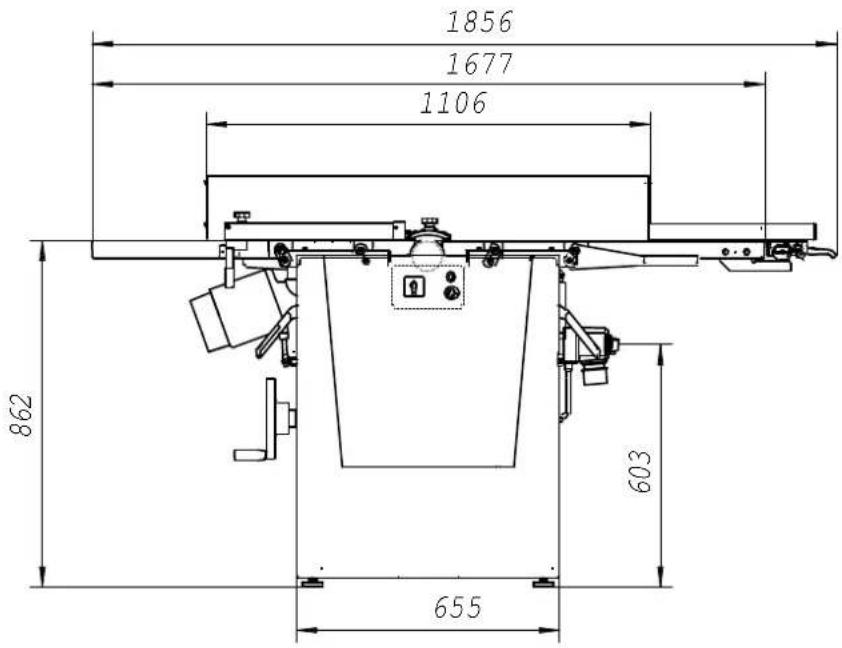
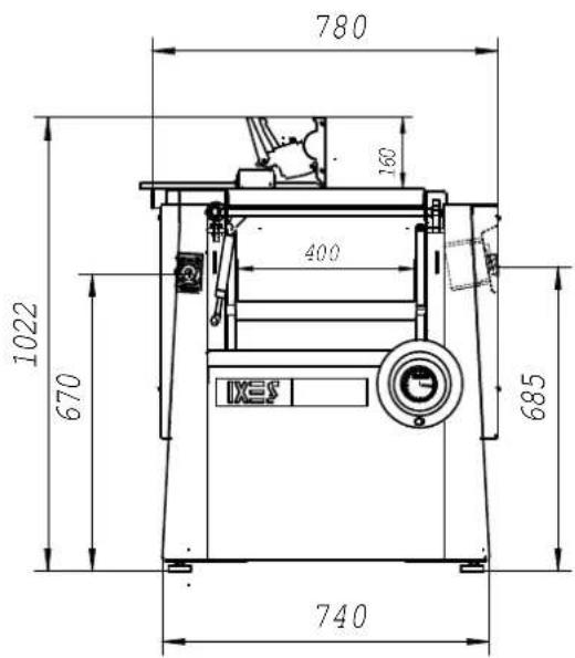
Dimensions:
Total length mm 1856
Total width mm 780
Total height mm 1022
Table height mm 862
Surface plate length mm 820
Surface plate width mm 442
Thicknessing table length mm 645
Thicknessing table width mm 410
Weight kg 325
Planing block:
Planing block ∅ mm 78
Knife cutting circle ∅ mm 80
Material of the planing block C45
Rotational speed max. 1/min 5400
Amount of planing knives Item 3
Measurements of the planing knife mm 3x12x410
Material of the planing knife mm HSS No. 3343
Forward feed:
Feed rollers Item 2
Surface gummed
Feed rollers ∅ mm 35.5
Length mm 398
Feed speed m/min 5/10
Can be switched off yes
Drive: 1902206902 1902206903
Three-phase current motor V 380-420/50 Hz 380-420/50Hz
Power consumption P1 KW 4.0 5,0
Output P2 KW 3.0 4,0
Motor speed 1/min. 2800 2800
Operating mode S 6/40 % S6/40%
Nominal current A 6.6 8,7
Work data:
Surfacing planing width max. mm 410
Surfacing depth of cut max. mm 5
Thicknessing planing width max. mm 400
Thicknessing depth of cut max. mm 5
Thicknessing capacity of the lathe min/max. mm 5/230
Standard accessories:
Adjustable surface planing fence
Lateral mm 410
Angle 90-45°
Stop length mm 1100
Stop height mm 160
Height planing block cover
! Subject to technical modification!
Noise characteristics
The noise emission values calculated according to EN 23746 for the sound power level and EN 31202 (correction factor k3 calculated in accordance with Appendix A.2 of EN 31204) for the sound pressure level at the workplace corresponds to the basis laid for working conditions in ISO 7904 Appendix A.
| Sound power level in dB (surfacing) |
| Idle running L_WA = 95.8 dB (A) Processing L_WA = 103.2 dB (A) |
| Sound pressure level at workplace in dB |
| Idle running L_pAeq = 83.2 dB (A) Processing L_pAeq = 93.5 dB (A) |
| Sound power level in dB (thicknessing) |
| Idle running L_WA = 96.6 dB (A) Processing L_WA = 102.0 dB (A) |
| Sound pressure level at workplace in dB |
| Idle running L_pAeq = 80.8 dB (A) Processing L_pAeq = 85.9 dB (A) |
For the emission values named, there is an addition for measuring uncertainty of K = 4 dB
Values for dust emission
The dust emission values measured by the technical committee “Wood” according to the “Basics for checking the dust emission (concentration parameter) of wood processing machines” are under 2 mg/m ^3 . When connecting the machine to a proper, operational suction with at least 20 m/s air speed, it can be assumed that the current TRK (Guideline for Technical Concentration) limit for wood dust in Germany will not be exceeded.
Installation
The machine is supplied ready-assembled and is thus ready for immediate operation.
Installation tool
The scope of delivery includes:
1 Torx wrench 62470123 (for changing the plane knife)
Operating instructions
Only lift the machine with the crane bow!
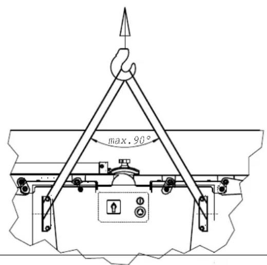
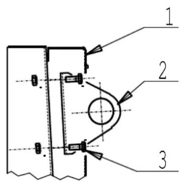
After setting up, remove the crane bow.
- Open the side cover 1
- Remove crane bow 2 after loosening the hexagon bolt 3.
Setup and adjustment
Fig. "A"
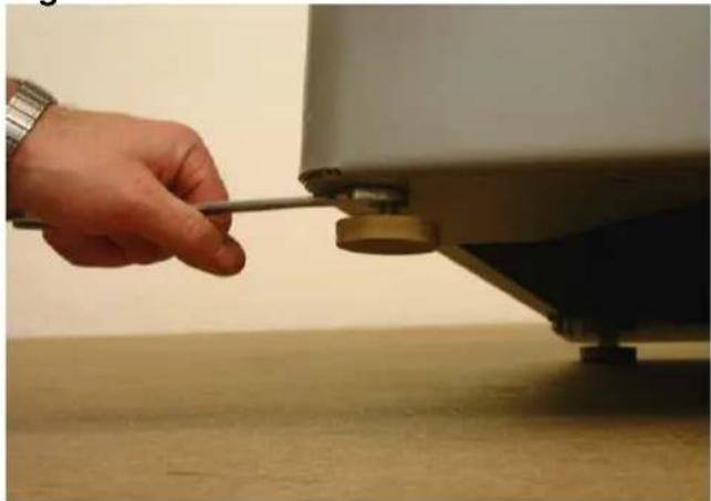
The machine stands on four adjustable rubber buffers.
Balancing out floor unevenness. Loosen the lower hexagon nuts using the wrench and screw the rubber buffers in or out as appropriate.
Tighten the hexagon nuts again(counterclockwise).
Fig. "A"
natural_image
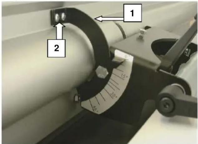
Hand holding a tool near a small mechanical component mounted on a table (no visible text or symbols)Surface planing fence
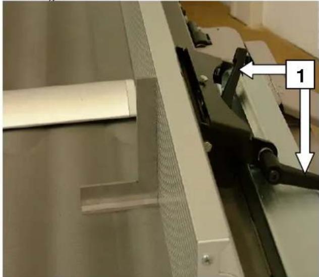
Fig. "B"
→ Setting the surface planing fence onto the machine
⇒ Find the 90° position with the aid of a back square
→ Pull the lock lever 1 tight.
Fig. "B"

natural_image
Close-up of a mechanical assembly with a metal bracket and tool, showing no visible text or symbols.Fig. "C"
Set fence screws 2 to the 90° and 45° position using a 10 span single-head wrench.
The surface planing fence can be swung to any position between 90^ - 45^ , when the handles on the swinging segments are loosened.
Set the 90° position with a back square. After setting each angle, check the exactness of the measurement on a trial piece using a protractor.
Fig. "C"

natural_image
Close-up of a mechanical device with directional arrows indicating movement or force, labeled '2' (no readable text or symbols beyond label)Fig. "D"
⇒ The clamping of the surface planing fence takes place via the two cam levers 3.
⇒ The surface planing fence is adjustable up to 410 mm above the plane width.
Fig. "D"
natural_image
Hand operating a machine with a handle, showing blade and frame structure (no text or symbols visible)Fig. "E"
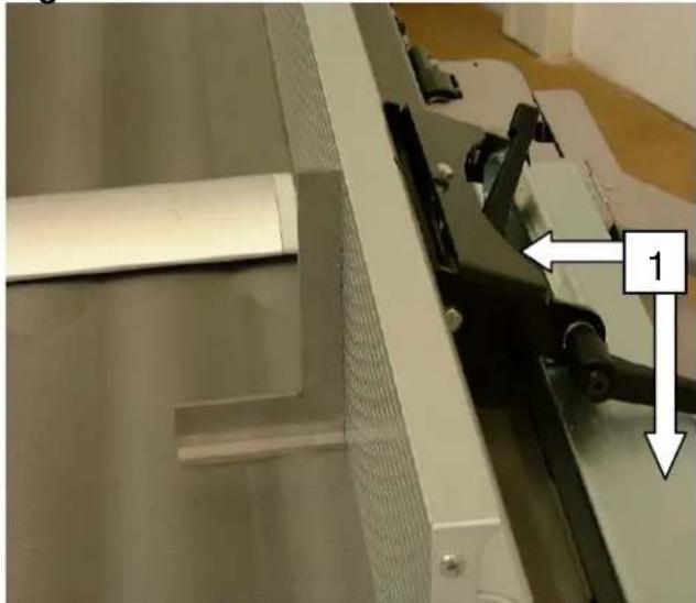
⇒ If there are differences, the pointer 1 can be reset by loosening the screws 2.
→ Correct the pointer, tighten the screws again.
Fig. "E"

Fig. "E1"
⇒ The planing block guard can be turned without a tool by pulling the cam lever upwards.
Pull the planing block guard away, push the cam lever downwards again.
Fig. "E1"
natural_image
Person operating a mechanical testing machine with a clamping tool (no visible text or symbols)Caution:
Never work without planing block guard while surface planing.
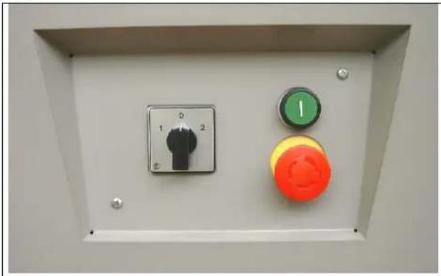
Electrical connection
Fig. "F"
Connect the machine to the mains with a CEE plug, the supply line must be protected with 16 A.
→ Switch main switch to the CEE plug in the I position
⇒ On the operating switch, press the green on-switch; the planing block starts to run.
→ Push the red mushroom-shaped button to shut down, planing block is braked within 10 sec.
When shutting down the planing block at the main switch (CEE plug), the braking function is ineffective!
⇒ The main switch is in the 0 position, the motor is free of current.
Fig. "F"
natural_image
Control panel with three buttons: one black push-button, one green push-button, and one orange push-button (no text or symbols visible)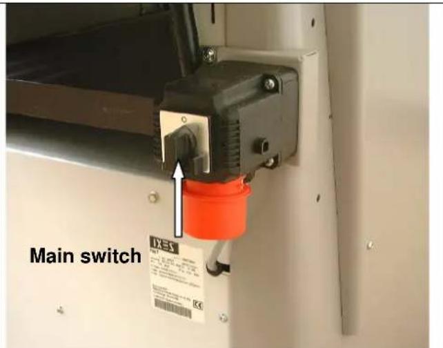
When connecting to the mains or changing the position, the rotational direction must be checked and when necessary the polarity switched using a screwdriver (machine socket).
Change in rotational direction
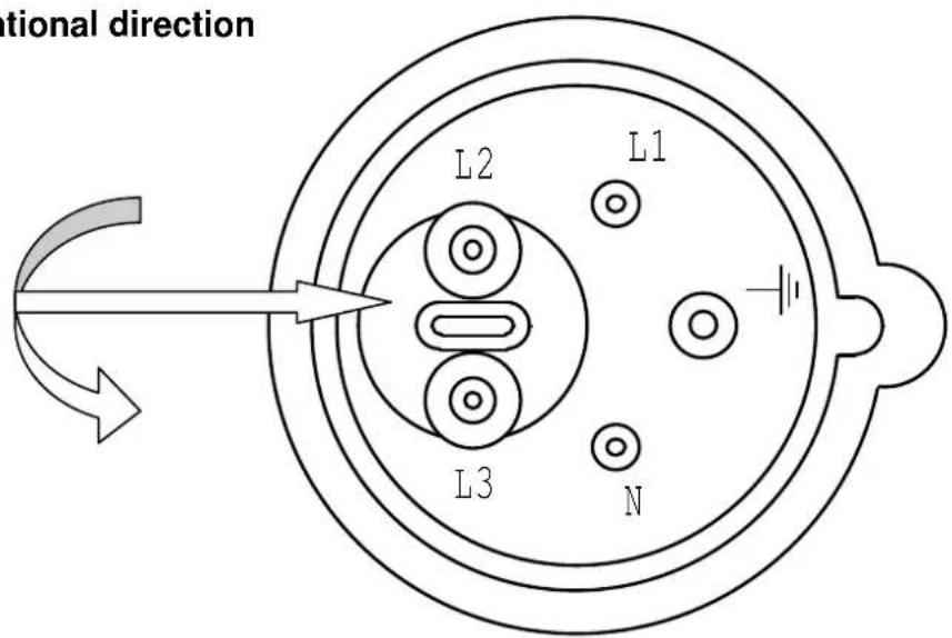
The electric motor installed is connected and ready for operation. The connection corresponds to the relevant VDE and DIN regulations. Connection to the mains by the customer and the extension cable used must correspond to these regulations.
Motor braking device
When shutting the machine down, an automatically effective regenerative brake is safely applied. The brakes brake the driving motor of the planing block within 10 sec. If the braking procedure lasts longer than 10 seconds, the machine may no longer be operated, since the brakes are defective. It is imperative that the machine is cut off from the source of power. Only professional electricians may be used to clear errors.
Operating mode / Working time
The electric motor is dimensioned for operating mode S 6 - 40 %.
S 6 = Continuous operation duty type
40 % = Referring to 10 min.: 4 min. load; 6 min. disengaged
When the motor is overloaded, it turns itself off by using a winding thermostat that is built into the motor windings. After a cooling period (of varying length), the motor can be switched on again.

Damaged electrical connection cables
Insulation damage often arises on electrical connection cables.
Possible causes:
⇒ Pressure points, when connection cables are led through windows or door frames.
→ Kinks due to improper fastening or guides for the connection cable.
⇒ Cuts caused by the connection cable being driven over.
→ Insulation damage arising from cable being ripped out of the wall socket.
⇒ Tears due to aging of the insulation. Such faulty electrical connection cables should no longer be used, as the damage to the isolation renders them life-threatening.
Regularly check electrical connection cables for damage. Make sure that the cable is not connected to the mains while checking. Electrical connection cables must correspond to the relevant VDE and DIN and the local EVE regulations. Only use connection cables with the identification number H 07 RN. It is mandatory for the type designation to be printed on the connection cable.
Extension cables must exhibit a cross section of 1.5 square millimeters (up to 25m length), and 2.5 square millimeters (over 25m length).
⇒ The mains connection is protected with 16 A (anti-surge).
Three-phase current motor
⇒ Supply voltage must be 380 - 420 V 50 Hz.
Mains connection and extension cable must have five wires = 3 P + N + SL.
→ Extension cables must have a minimum cross section of 1.5 mm ^4 .
⇒ The mains connection is protected with a maximum of 16 A.
When connecting to the mains or changing the position, the rotational direction must be checked and the polarity switched where necessary.

Connection and repairs of electrical equipment may only be carried out by qualified professionals. In the case of inquiries, please quote the following data:
→ Motor manufacturer; motor model
⇒ The motor's type of current
→ Data of the machine's type plate
→ Data of the electronic control system
If returning the motor, always send the complete drive unit with electronic control system.
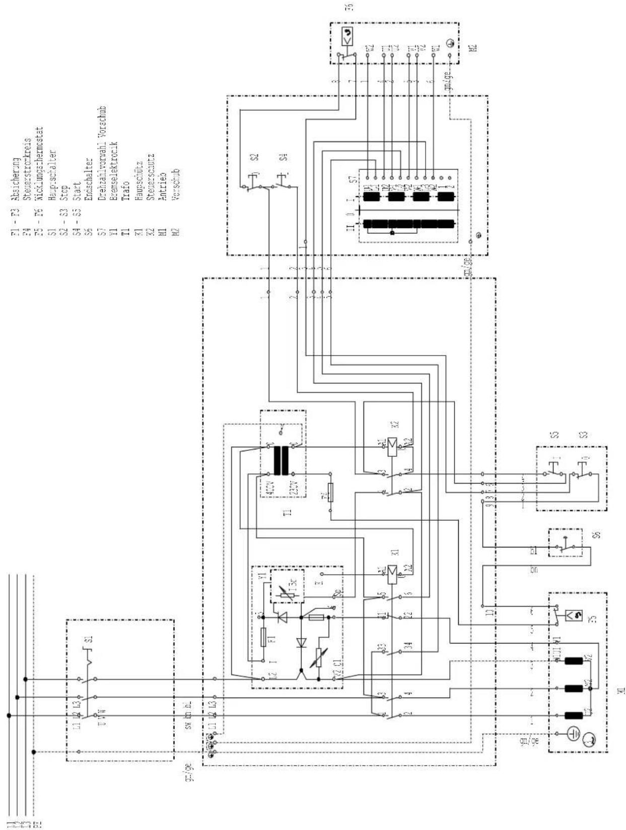
Circuit diagram 380-420V
Initial operation
→ Before initial operation, observe the following safety notes.
→ The complete set of protective and auxiliary devices must be installed.
⇒ Equipping, adjusting, measuring and cleaning work may only be carried out with the motor switched off. Pull the mains plug or switch the main switch to the 0 position, and wait for the rotating tool to come to a standstill.
Surface planing – Chip removal
Fig. "G"
During surface planing, the chip removal can be set anywhere from 0 ÷ 5 mm using the articulated lever 1.

Fig. "G"
natural_image
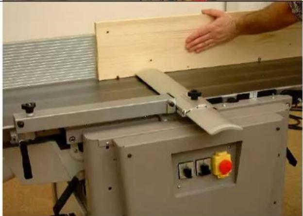
Industrial machine with conveyor belt and pipe fittings, no visible text or symbolsSurface plane – Planing block guard
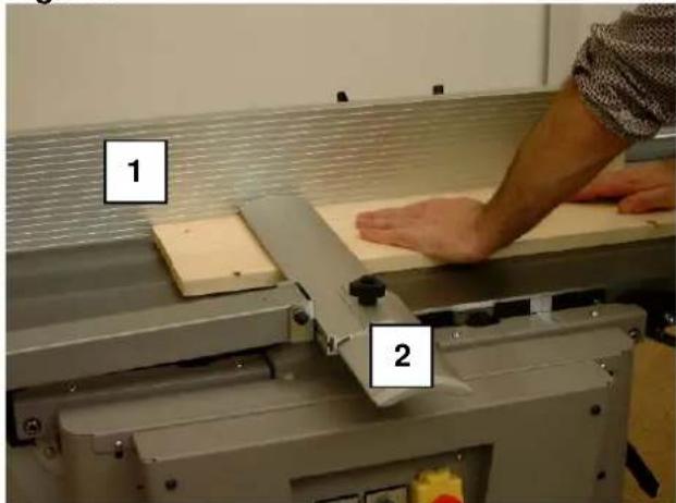
Fig. "H"
When surfacing workpieces up to 75 mm in thickness, the planing block guard must cover the workpiece and the planing block from above. With a workpiece width greater than 75 mm, place the planing block guard's guard rail on the full width of the workpiece. Make sure that your hands are closed and your thumbs are tucked in when you lay them on the workpiece.
1 Surface planing fence
2 Planing block guard
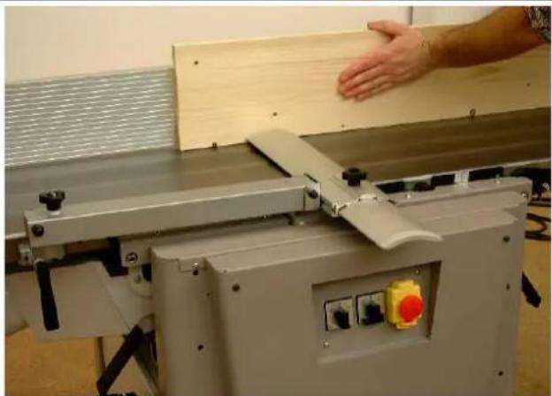
Jointing
Fig. "J"
For this working cycle, use the surface planing fence, leave the planing block guard lying on the dressing table, and place the guard rail over the width of the workpiece.
Press the workpiece against the plane ledge and guide it over the planing block with both hands. As soon as the board sufficiently extends into the collection table, place you left hand and smoothly push it over the knife block.
Fig. "H"
natural_image
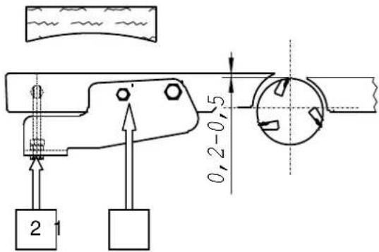
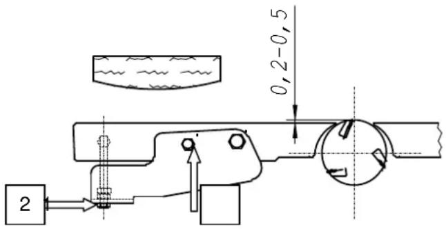
Industrial machine with wooden panel and hand interacting with a hand (no visible text or symbols)Adjusting the joint
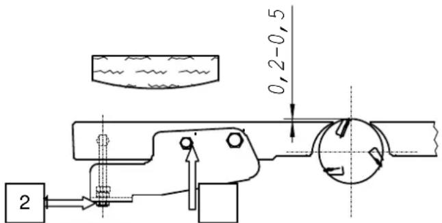
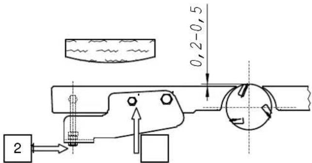
The workpiece length was preset at the factory at two meters, creating a hollow joint of about 0.2 - 0.5 mm. For special demands (prominent convex, concave or straight joints), the collection table must be adjusted.
Prominent concave joints
Dressing table above the knife cutting circle
Loosen binding screw 1
Using adjusting screw 2, adjust the table upwards (max. 0.5 mm)
Tighten the binding screw 1 again
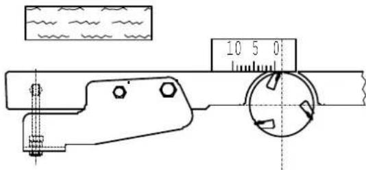
Straight joints
Dressing table on the same level with the knife cutting circle
Put a gauge onto the dressing table and turn the planing block with your hand. The planing block should pull the gauge along for 2 - 3 mm.
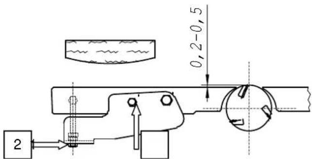
Prominent convex joints
Dressing table under the knife cutting circle
Loosen binding screw 1
Using adjusting screw 2, adjust the table downwards (max. 0.5 mm)
Tighten the binding screw 1 again

Surface planing – Chipping ejection
Fig. "K"
When surface planing, both dressing tables must be locked.
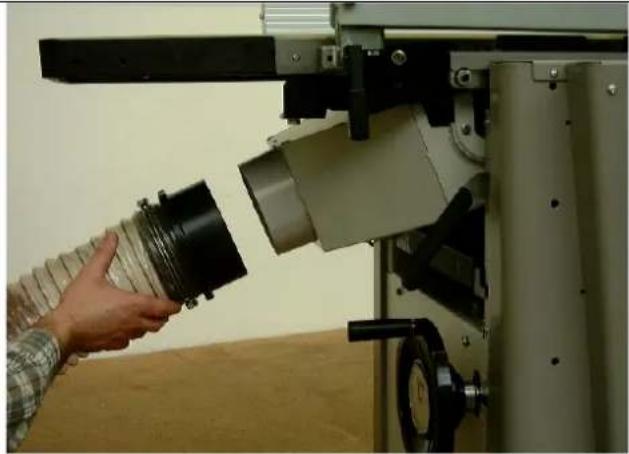
Put the suction hose on the suction hood.
Suction can take place in combination with a dust extractor.
Suction nozzle radius 140 mm
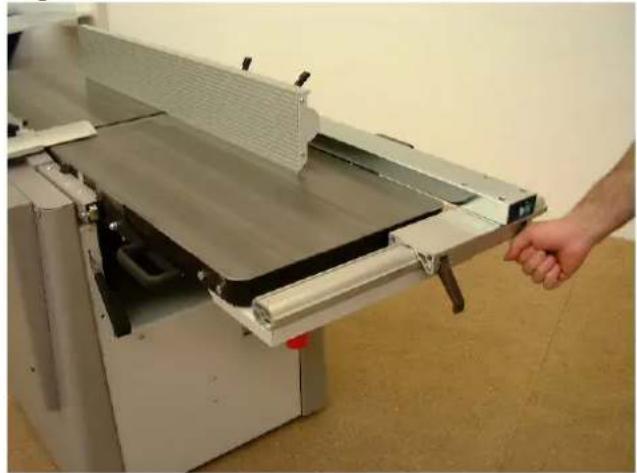
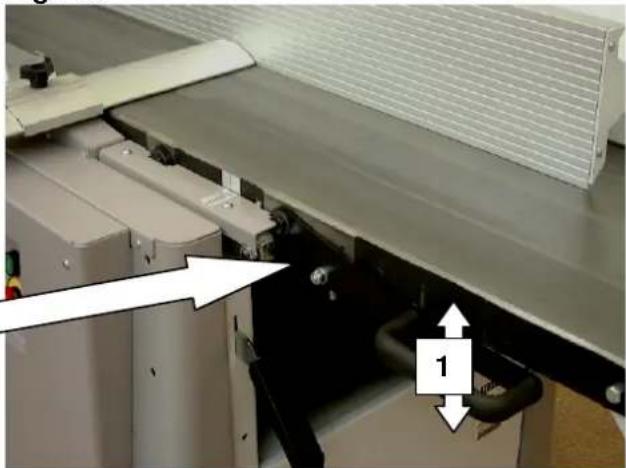
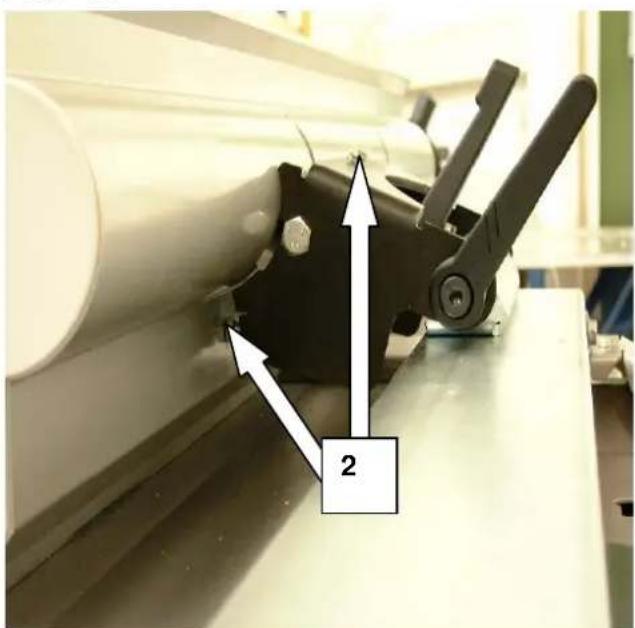
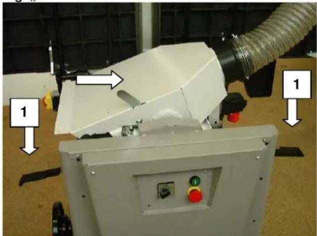
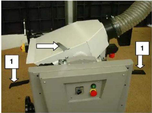
Thicknessing – Machine settings
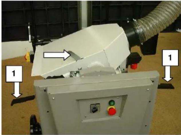
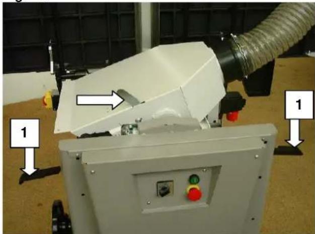
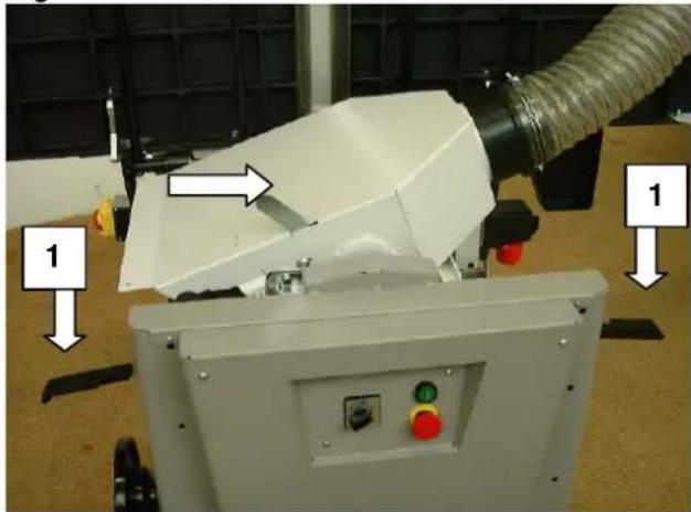
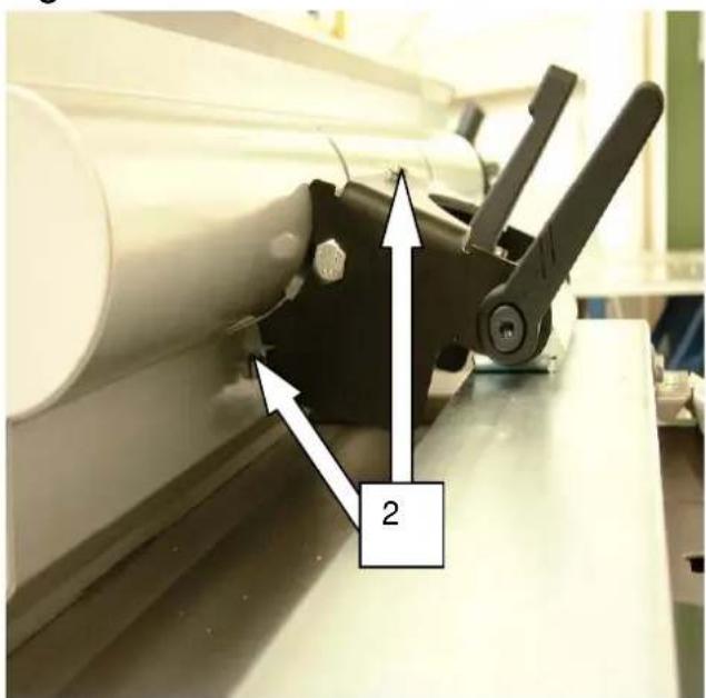
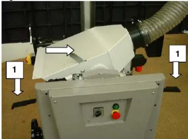
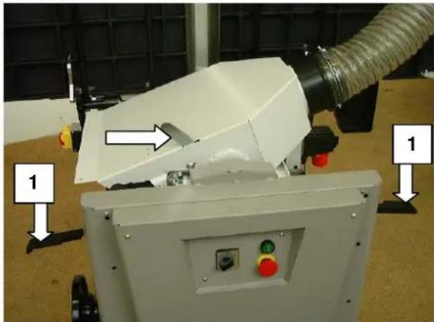
Fig. "L"
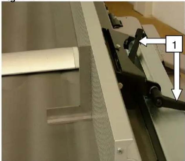
Lift the lock lever 1 and open both dressing tables.
Swing up and lock the chipping hood (arrow).
Suction can take place in combination with a dust extractor.
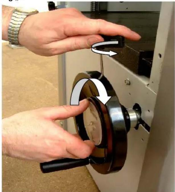
Thicknessing – Table adjustments
The thicknessing table can be adjusted for height using the handwheel.
The integrated position indicator shows the passage height of 5 - 230 mm.
One turn of the handwheel corresponds to 2 mm. Always keep the thicknessing table as well as the dressing table free of resin. Clamping thickness max. 5 mm.
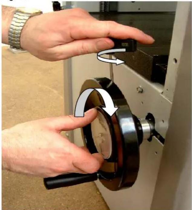
Position indicator correction
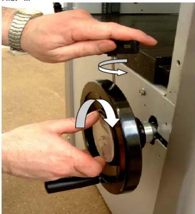
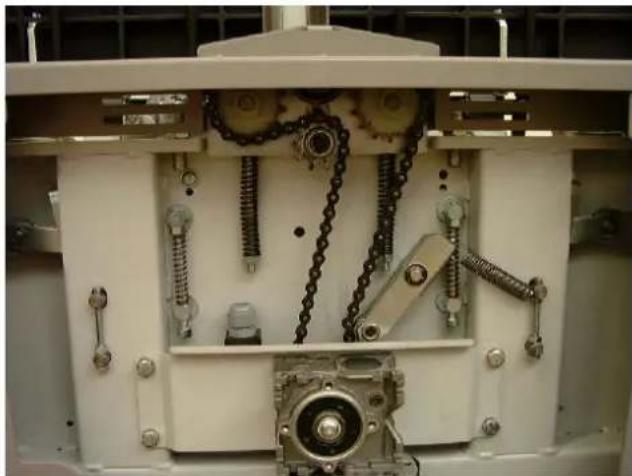
Fig. "M"
The thickness dial can be corrected for inexact measurements.
Example:
The passage height is set to 100 mm.
The processed workpiece shows a measurement of 101 mm.
Loosen the fastening screw on the side of the handwheel.
Turn and set the dial on the position indicator to 101 mm.
Tighten the fastening screw on the handwheel again.
natural_image
Person using a microscope to interact with a cylindrical lens, no visible text or symbolsFig. "L"

natural_image
Industrial robotic device with labeled components and directional arrows (no readable text or symbols)Fig. "M"

natural_image
Close-up of hands operating a mechanical device with a rotating knob and handle (no visible text or symbols)Thicknessing – Feed
Fig. "N"
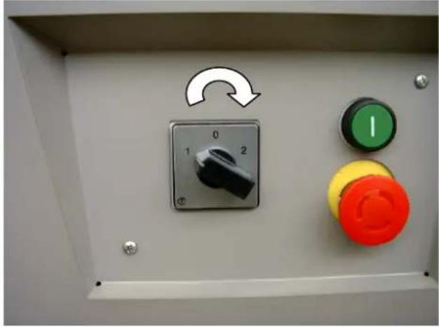
The feed can be switched on and off with the cam controller.
$$ 0 = \text { Off } $$
$$ 1 = \text { ON } 5 \mathrm{m} / \mathrm{min} $$
$$ 2 = \text { ON } 1 0 \mathrm{m} / \mathrm{min} $$
⇒ First switch the feed on and the put the workpiece on.
⇒ The feed motor only runs when the planing block is running.
Setting the feed speed
When working with workpieces up to approx. 100 mm wide, a max. chip removal of 5 mm can be planed with level 2.
With wide workpieces, level 1 should be set with max. chip removal in order to achieve a clean workpiece surface.
⇒ The feed speed can be changed even when under load.
Maintenance

Perform maintenance, repair and cleaning work as well as service malfunctions only when the machine is switched off!
Switch the main switch to the 0 position or pull the plug!
The complete protective and safety devices must be remounted following repair and maintenance work.
Always keep the thicknessing table as well as the dressing table free of resin. Pharmol-HEK concentrated resin remover Item No. 6100 9700 is available at your SCHEPPACH dealer.
⇒ The planing block's bearing and the workpiece spindle are provided with permanent lubrication. When the machine is new, warming may occur due to the design, but will disappear after a while.
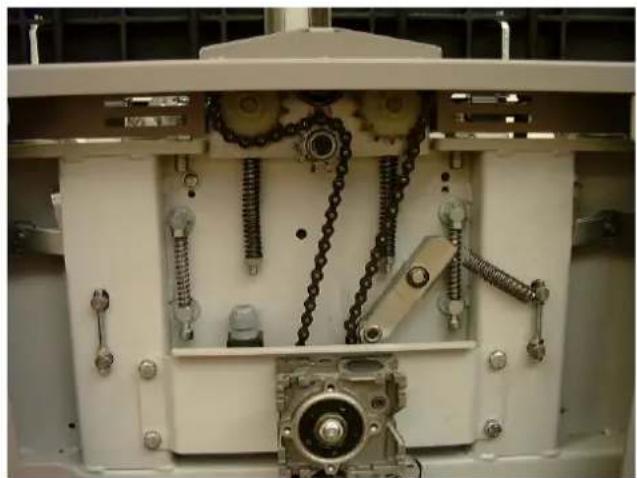
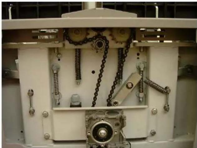
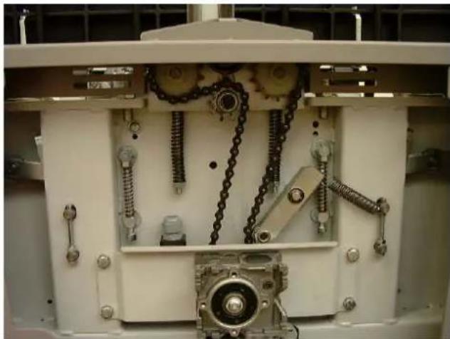
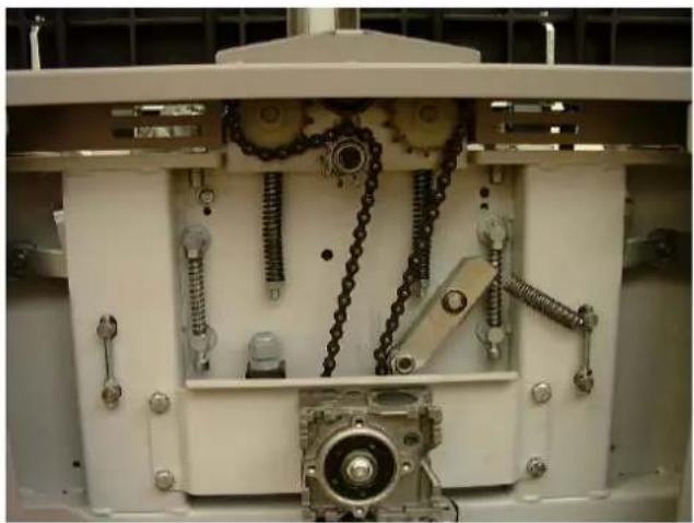
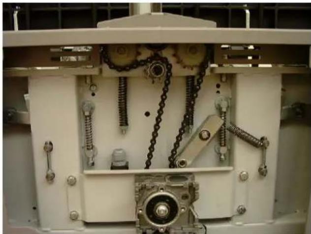
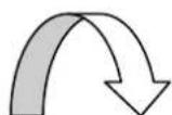
Fig. "O"
⇒ Regularly clean the feed rollers.
Occasionally oil the plain bearings of the feed rollers.
Occasionally oil the adjusting spindle of the thicknessing table, its bearings as well as the jointed driving shaft.
⇒ Check chain tension. If needed, regulate the tension and oil. When regulating the tension of the thicknessing table's chain, be aware of the parallelism to the thicknessing table.
Fig. "N"
natural_image
Control panel with rotary knob, two switches (green and red), and a green circular indicator (no text or symbols visible)Fig. "O"
natural_image
Interior view of a mechanical assembly with chain links and gears (no visible text or symbols)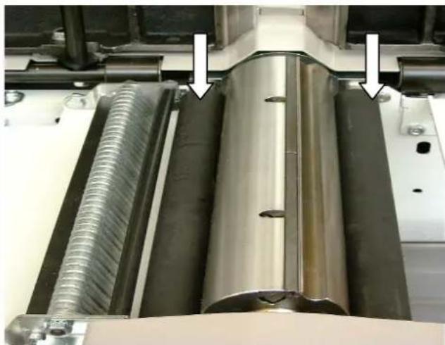
natural_image
Close-up of industrial machinery components with metallic and threaded metal parts, no visible text or symbolsV belt tension Fig. "P"
→ Open the side plate with a wrench
→ Loosen lock lever "A"
→ Press the motor-driven rocker dolly switch down
⇒ Pull the lock lever "A"
→ Close the side plate again
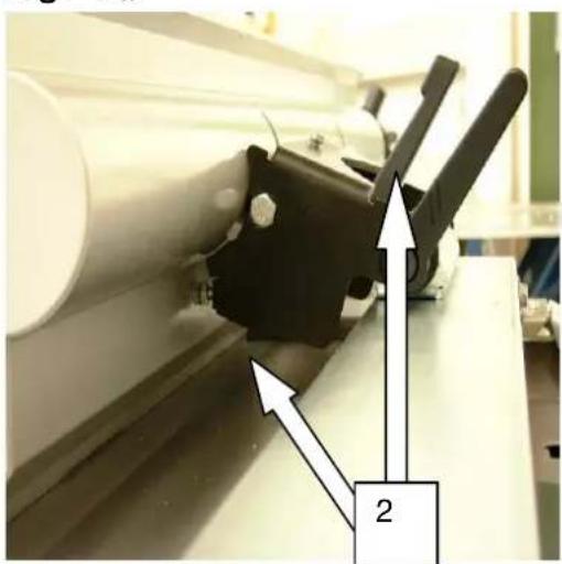
Feed roller settings Fig. "R"
In order to guarantee smooth feeding, the compression springs must be adjusted to the measurements opposite.
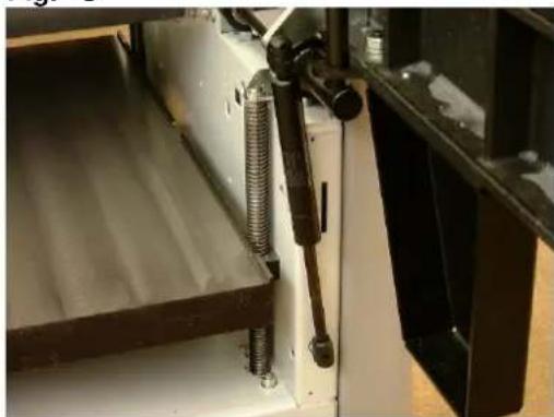
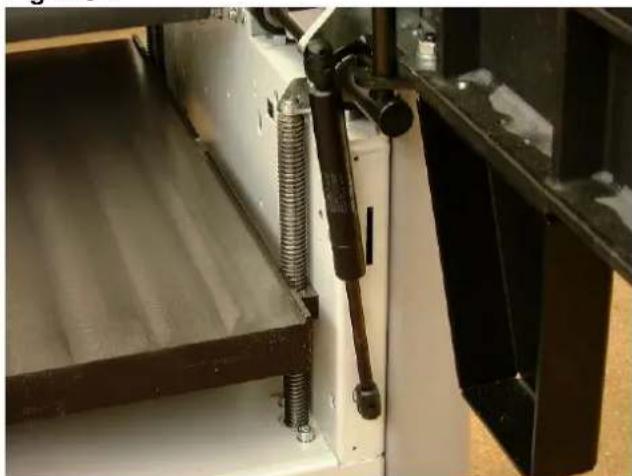
Dressing table safety device Fig. "S"
⇒ In order to avoid an unintentional closure of the dressing table, both dressing tables are equipped with a pneumatic spring action.
⇒ When closing the dressing table, no additional safety device needs to be removed.

natural_image
Person operating a mechanical device in a workshop, with an arrow pointing to a component (no visible text or symbols)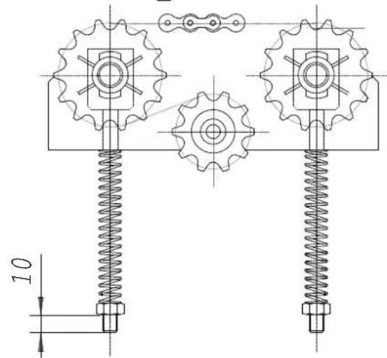
Fig. "S"
natural_image
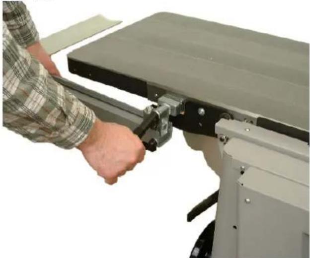
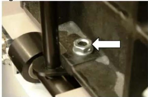
Close-up of a mechanical assembly with coiled spring and metal components (no visible text or symbols)Dressing table Fig. "T"
During surface planing, the chip removal can be set anywhere from 0 – 5 mm using the articulated lever.
If the dressing table moves while work is in process, an accurately measured chip removal will not be possible. In this case, the four hexagon bolts must be tightened, so that the dressing table once again holds the adjusted chip removal.
Planing knife
Caution!

The planing knives used are disposable knives and therefore can not be resharpened, but only used once.
The planing knives supplied by the factory are sharpened, ready for operation and correctly adjusted.
Only well sharpened and exactly adjusted planing knives can guarantee safe work
We recommend that you:
Use only original "SCHEPPACH" planing knives.
Replacement knives with the Item. No. 6247 0702 are available at your dealer.
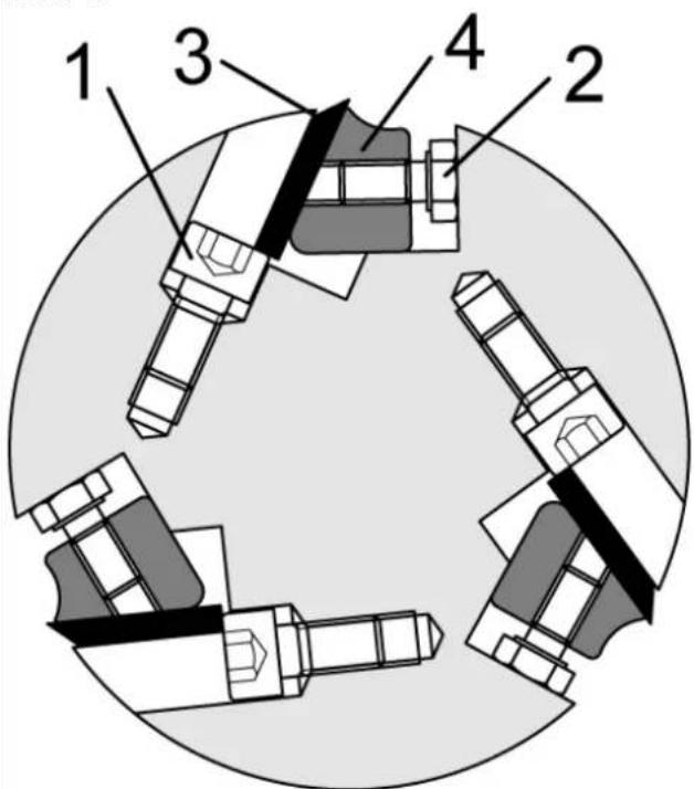
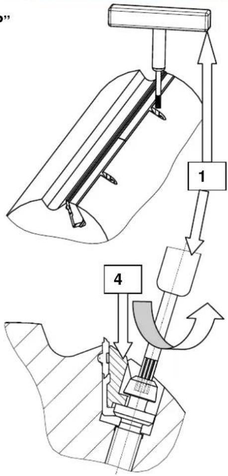
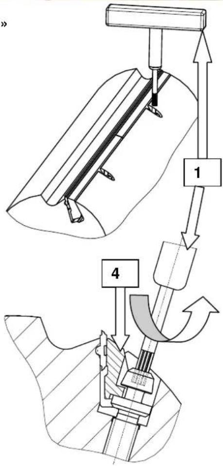
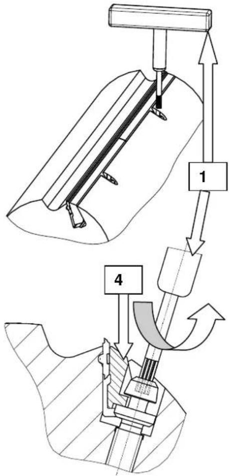
Changing planing knives Fig. "P"
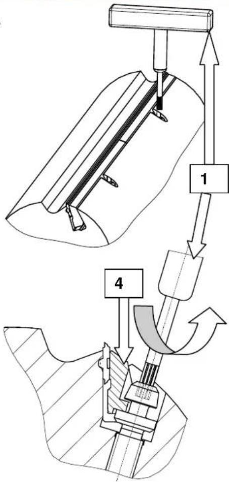
For every planing knife loosen both tensioning wedges 4) with the wrench 1) until you have reached the noticeable stop. Loosen the screw by turning counterclockwise, the screw moves down
(Attention: left-handed thread)
The tensioning wedge moves downward as the screw is loosened, the planing knife becomes free.
Fig. "T"
natural_image
Close-up of a mechanical assembly with a bolt and pipe fitting, featuring a white arrow pointing to a specific component (no text or symbols visible)Fig. "P"

natural_image
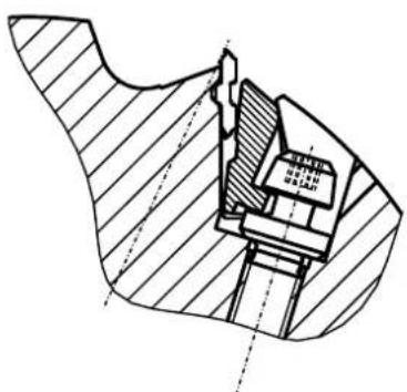
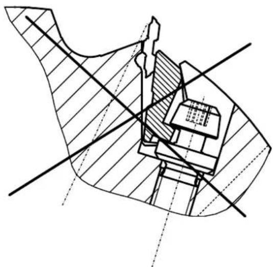
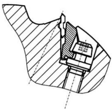
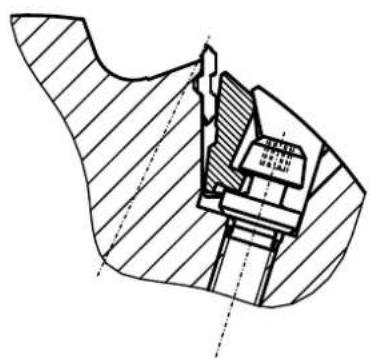
Technical cross-sectional diagram of a mechanical assembly (no visible text or labels)The planing knife can only be completely removed and replaced again.
When installing the planing knife, be aware that the planing knives are flush to the side with the planing block.
Every time the knife is changed, the planing knife and the V ledge should be cleaned.
Caution! Fingers and hands can be injured while changing the knives.
Caution!

Check if the reversible blade is correctly positioned through the interlocking connection between the guiding groove in the base and the key of the reversible blade, and has the correct tension through the tensioning wedge.
The planing block may be operated with all three reversible blades. When operating with one or two, beware of accidents and unbalanced operations.
Breakaway torque of the screw 10 Nm.
Caution!

Danger of accident if improperly installed!
natural_image
Technical diagram of a mechanical assembly with cross-hatching and dimension lines (no readable text or symbols)
natural_image
Technical line drawing of a mechanical component with a cylindrical body and internal structure, showing a dimension arrow (no text or symbols)
natural_image
Technical line drawing of a mechanical assembly with hatched sections and internal components (no text or symbols)
natural_image
Cross-sectional technical diagram of a mechanical assembly with no visible text or symbolsPrevious to initial operation, the planing block must be checked, if the above mentioned instructions were correctly implemented.
Before turning on the machine, make sure you are familiar with all general safety measures.
Fault finding
When correcting faults, switch off the machine. Pull out the plug.
Irregular and failed transportation during thicknessing
| Cause Remedial action | |
| Thicknessing table has resin on it especially when machining moist and resinous kinds of wood. | Regularly clean the thicknessing table. Treat the thicknessing table with Pharmol dry - lubricating spray |
Workpiece not correctly cut when surface planing
| Cause Remedial action | |
| Blunt planing knife Turn the planing knife, or replace it | with a new planing knife. See operating instructions “Adjusting planing knife” |
Workpiece not even (bulged or hollow) when surfacing
| Cause Remedial action | |
| Dressing tables are not standing parallel to one another or are not exactly in the cutting circle of the planing block. | Reset the feed table parallel to the collection table.Lay a long, straight ruler over both table tops for setup.Adjust the collection table, seeAdjusting the joint. |
The machine does not run
| Cause Remedial action | |
| Planing block's motor does not run | ⇒ Switch on the main switch⇒ Check the operating network's feed line⇒ Check the fuses (included 16 A)⇒ Close the suction hood or dressing table correctly so that the limit switch is switched on |
| Feed motor does not run | ⇒ Switch on the machine⇒ Check the fine-wire fuses 10 A in the timing gear case within the machine |
Planing block does not brake when switching off
| Cause Remedial action | |
| Fine-wire fuse on the brake plate is defective | ⇒ Check the fine-wire fuses on the brake plate 10 A in the timing gear case within the machine |
| Brake plate is defective | ⇒ Replace the brake plate |
Repairs of electrical equipment may only be carried out by qualified professionals.
Special accessories Order number:
Attachment module for slot-boring attachment 6247 0701
⇒ HS planing knife (1 set = 3 pieces) 6247 0702
→ Wheel set with brackets 6247 0703
→ HW planing knife 6247 0704
→ Attachment for small workpieces 6247 0705
→ Slot-boring attachment Lbe 16 6331 0000
⇒ Slot-boring replacement 6330 4000
EC declaration of conformity
hereby declare that the machine referred to in the following conforms to the following relevant provisions of the EC directives with respect to its construction and design as well as the version which has been released from our factory.
This declaration loses its validity if the machine is modified. The machine corresponds to the checked sample.
Machine description: Planing machine Plana 7.0
Machine model: 1902206902/1902206902
Relevant EC directives: EC machine directive 2006/42/EG
EC-EMV directive 2004/108/EWG.
Related harmonised
European norms: EN 861, EN 847-1, EN 60204-1
EC type examination: (EC type examination certificate 011024)
Apparent defects are to be reported within eight days after the goods have been received, otherwise the purchaser loses all claims relating to such defects. We offer a guarantee for machines which have been handled properly for the duration of the legal period of warranty from the time of delivery in that we shall replace, at no extra charge, every machine part that has proved itself to be unserviceable resulting from material or manufacturing defects within this time. For parts which we have not manufactured ourselves, our coverage is limited to the warranty claims offered by the supplier. The replacement costs for the new parts will be met by the purchaser. Cancellation of sale and reduction of price and other claims for damages are excluded.
Constructeur :
Günzburger Straße 69
D-89335 Ichenhausen
Chers clients,
DÉCLARATION DE CONFORMITÉ CE
GARANTIE
natural_image
Hand holding a tool near a small mechanical component (no visible text or symbols)Fig. « B »
natural_image
Close-up of a mechanical assembly with a numbered component (1) and alignment lines, no readable text or symbols present.Fig. « C »

natural_image
Close-up of a mechanical device with labeled components and directional arrows, no readable text or symbols present.Fig. « D »
natural_image
Hand operating a machine with metal components and a handle, no visible text or symbolsFig. « E »
Fig. « E1 »
natural_image
Person using a mechanical clamp to adjust or install a large cylindrical component (no visible text or symbols)natural_image
Interior view of an industrial control panel with three buttons (labeled 1, 2, 3) and a green indicator light (no text or symbols beyond labels)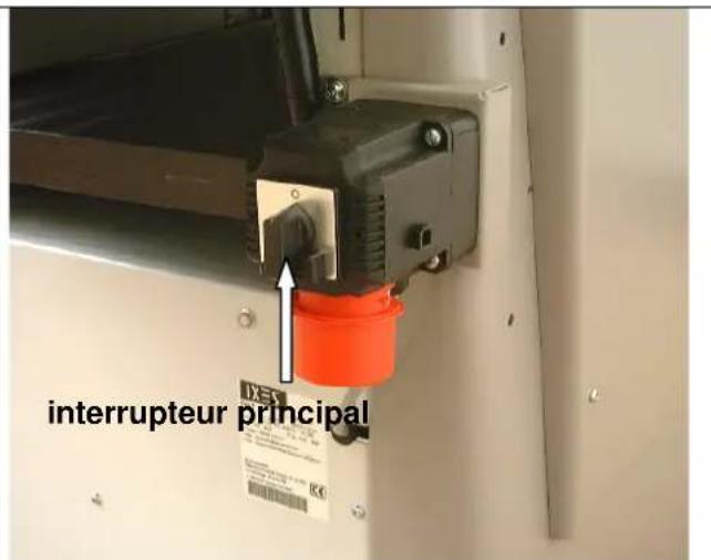
natural_image
Industrial machine with conveyor belt and control panel, showing directional arrows and dimension label '1' (no readable text or symbols)natural_image
Industrial machine with wooden panel and hand interacting with a wooden workpiece (no visible text or symbols)Réglage du joint
natural_image
Person using a microscope to interact with a cylindrical lens component (no visible text or symbols)Fig. « L »
natural_image
Industrial robotic device with white housing and red control buttons, labeled '1' arrows pointing to components (no readable text or symbols)Fig. « M »

natural_image
Close-up of hands operating a mechanical device with a rotating knob and adjustment arrows (no text or symbols visible)Rabotage – Avance
Fig. « N »
natural_image
Control panel with rotary knob and indicator lights (no text or symbols visible)Fig. « O »
natural_image
Interior view of a mechanical device with visible gears, springs, and tubing (no text or symbols)
natural_image
Close-up of industrial machinery components with metallic and threaded metal parts, no visible text or symbolsnatural_image
Person operating a mechanical device in a workshop, with an arrow pointing to a component (no visible text or symbols)
Fig. « S »
natural_image
Close-up of a mechanical assembly with metal components and a coiled spring (no visible text or symbols)natural_image
Close-up of a mechanical component with a metallic bolt and pipe fitting, featuring a white arrow pointing to a small hole (no text or symbols visible)Fig.: « P »


natural_image
Technical cross-sectional diagram of a mechanical assembly (no text or labels)natural_image
Technical diagram of a mechanical assembly with cross-hatching and dimension lines (no readable text or symbols)
natural_image
Technical line drawing of a mechanical component with a cylindrical body and internal structure, showing a dimension arrow (no text or symbols)
natural_image
Technical line drawing of a mechanical assembly with hatched sections and internal components (no text or symbols)
natural_image
Cross-sectional technical diagram of a mechanical assembly with no visible text or symbolsGünzburger Straße 69
D-89335 Ichenhausen
Gentile cliente,
natural_image
Hand holding a tool interacting with a mechanical component (no visible text or symbols)Fig. "B,"

natural_image
Close-up of a mechanical assembly with a numbered component (1) and directional arrows, no readable text or symbols present.Fig. "C,"
natural_image
Close-up of a mechanical device with directional arrows indicating motion or force, no visible text or symbolsFig. "C,"
natural_image
Hand operating a machine with a handle, showing blade and frame structure (no text or symbols visible)Fig. "E,"
Fig. "E1,"
natural_image
Person adjusting a mechanical device with a clamping tool (no visible text or symbols)Attenzione:
natural_image
Interior view of an electrical control panel with three buttons (black, green, red) and a switch (no text or symbols visible)
natural_image
Industrial machine with conveyor belt and pipe fittings, no visible text or symbolsnatural_image
Industrial machine with wooden panel and hand interacting with a hand (no visible text or symbols)natural_image
Control panel with rotary knob, green indicator lights, and red/green buttons (no text or symbols visible)Fig. "O,"
natural_image
Interior view of a mechanical assembly with chains and gears (no visible text or symbols)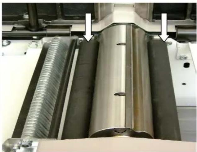
natural_image
Close-up of industrial mechanical components with metallic and threaded parts, no visible text or symbolsnatural_image
Person operating a mechanical device in a workshop, with an arrow pointing to a component (no visible text or symbols)
Fig. "S,"

natural_image
Close-up of industrial machinery components including a metal sheet and threaded spring, with no visible text or symbols.natural_image
Close-up of a mechanical component with a metallic bolt and pipe fitting, labeled 'Fig. "T,"' with an arrow pointing to the bolt (no text or symbols on the object itself)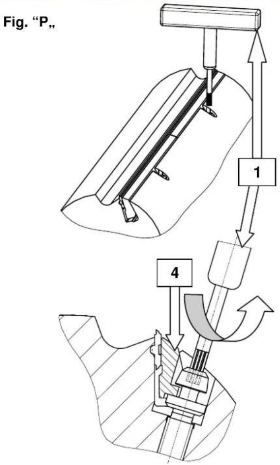

natural_image
Technical drawing of a mechanical assembly with cross-hatching and dimension lines (no text or symbols)natural_image
Technical line drawing of a mechanical assembly with cross-hatching and dimension lines (no readable text or symbols)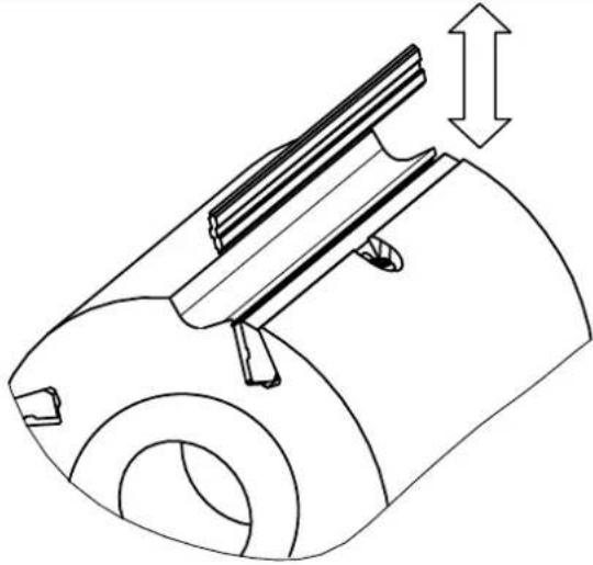
natural_image
Technical line drawing of a mechanical component with a cylindrical body and internal structure, showing a dimension arrow (no text or symbols)
natural_image
Technical line drawing of a mechanical assembly with hatched sections and internal components (no text or symbols)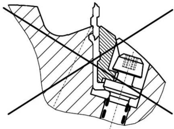
natural_image
Technical cross-sectional diagram of a mechanical assembly (no text or labels)Günzburger Straße 69
D-89335 Ichenhausen
Geachte klant,
natural_image
Hand holding a tool near a laptop stand (no visible text or symbols)Afb. "B"

natural_image
Close-up of a mechanical assembly with a numbered component (1) and alignment lines, no readable text or symbols present.Afb. "C"
natural_image
Close-up of a mechanical device with directional arrows and label '2' (no readable text or symbols beyond labels)Afb. "D"
natural_image
Hand operating a machine with a metal tray and handle, no visible text or symbolsAfb. "E"
natural_image
Person operating a mechanical testing machine with a clamping tool (no visible text or symbols)Let op:
natural_image
Interior view of an industrial control panel with three buttons (green, orange, red) and a black push-button switch (no text or symbols visible)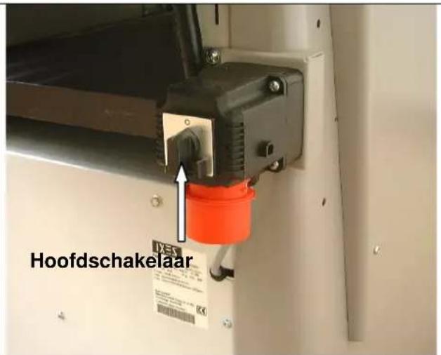
natural_image
Industrial machine with conveyor belt and control panel, showing directional arrows and dimension label '1' (no readable text or symbols)Vlakschaven – schaafasbeveiliging
Afb. "H"
natural_image
Industrial machine with hand operating a wooden board, no visible text or symbolsnatural_image
Person using a microscope to interact with a cylindrical lens, no visible text or symbolsAfb. "L"

natural_image
Industrial robotic device with white housing and red control buttons, labeled '1' arrows pointing to components (no readable text or symbols)Afb. "M"
natural_image
Close-up of hands operating a mechanical device with a rotating knob and adjustment arrows (no text or symbols visible)Vandikteschaven – voeding
Afb. "N"
natural_image
Close-up of an industrial control panel with rotary knob, switches, and indicator lights (no text or symbols visible)Afb. "O"

natural_image
Interior view of a mechanical assembly with chains and gears (no visible text or symbols)
natural_image
Close-up of industrial machinery components with metallic and threaded metal parts, no visible text or symbolsnatural_image
Close-up of a mechanical assembly with a coiled spring and metal components (no visible text or symbols)natural_image
Close-up of a mechanical component with a metallic bolt and pipe fitting, showing a white arrow pointing to a small hole (no text or symbols visible)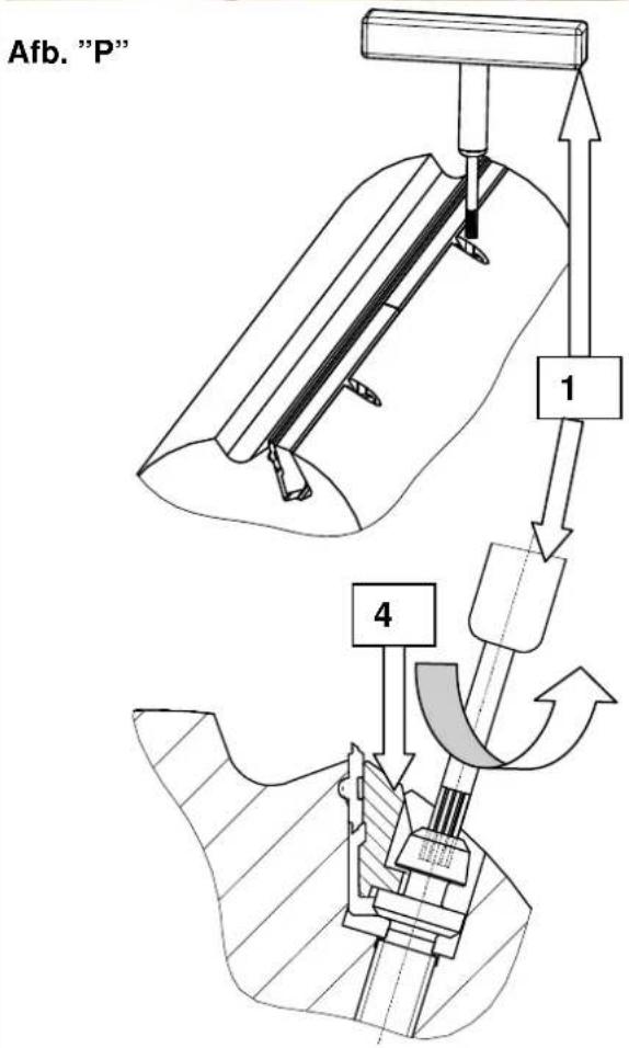

natural_image
Technical cross-sectional diagram of a mechanical assembly (no text or labels)natural_image
Technical diagram of a mechanical assembly with cross-sectional view and hatched fill (no text or labels)
natural_image
Technical line drawing of a mechanical component with a cylindrical body and internal structure, showing a dimension arrow (no text or symbols)
natural_image
Technical line drawing of a mechanical assembly with hatched sections and internal components (no text or symbols)
natural_image
Cross-sectional technical diagram of a mechanical assembly with no visible text or symbolsGünzburger Straße 69
natural_image
Hand holding a tool near a mechanical component (no visible text or symbols)Fig. "B"

natural_image
Close-up of a mechanical assembly with a metal bracket and tool, showing no visible text or symbols.Fig. "C"
Tope de planeado
Fig. "B"
natural_image
Close-up of a mechanical device with directional arrows indicating movement or force, no visible text or symbolsFig. "D"
natural_image
Hand operating a machine with a handle, showing blade and frame structure (no text or symbols visible)Fig. "E"
natural_image
Person using a mechanical clamp to adjust or install a large gray panel on an industrial machine (no visible text or symbols)Advertencia:
natural_image
Control panel with three buttons (black, green, orange) and a numeric input (1-3), no visible text or symbols beyond controls.
natural_image
Industrial conveyor belt system with directional arrows and labeled component '1' (no readable text or symbols)
natural_image
Industrial machine with wooden panel and hand interacting with a wooden board (no visible text or symbols)Ajuste de la ranura
natural_image
Person using a microscope instrument to interact with a cylindrical lens (no visible text or symbols)Fig. "L"
natural_image
Industrial machine with attached duct and control panel, labeled arrows pointing to components (no readable text or symbols)Fig. "M"

Regruesamiento – Avance
Fig. "N"
natural_image
Control panel with rotary knob, two switches (green and red), and a green circular indicator (no text or symbols visible)Fig. "O"

natural_image
Interior view of a mechanical assembly with gears, springs, and bolts (no visible text or symbols)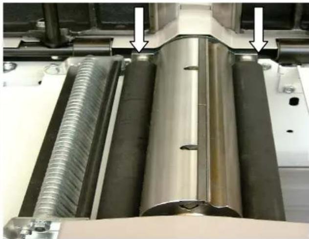
natural_image
Close-up of industrial machinery components with metallic and threaded metal parts, no visible text or symbolsnatural_image
Close-up of a mechanical assembly with a coiled spring and metal components (no visible text or symbols)natural_image
Close-up of a mechanical component with a bolt and pipe fitting, no visible text or symbolsFig. "P"


natural_image
Technical cross-sectional diagram of a mechanical assembly (no text or labels)natural_image
Technical diagram of a mechanical assembly with cross-sectional view and hatched fill (no text or labels)
natural_image
Technical line drawing of a mechanical component with a cylindrical body and internal structure, showing a dimension arrow (no text or symbols)
natural_image
Technical line drawing of a mechanical assembly with hatched sections and internal components (no text or symbols)
natural_image
Cross-sectional technical diagram of a mechanical assembly (no visible text or labels)Günzburger Straße 69
D-89335 Ichenhausen
Estimado cliente,
natural_image
Hand holding a tool interacting with a mechanical component (no visible text or symbols)Fig. «B»

natural_image
Close-up of a mechanical assembly with a metal bracket and tool, showing no visible text or symbols.Fig. «C»

natural_image
Close-up of a mechanical device with directional arrows and label '2' (no readable text or symbols beyond labels)Fig. «D»
natural_image
Industrial machine with a hand operating the blade (no visible text or symbols)Fig. «E»
Fig. «E1»
natural_image
Person using a mechanical clamp to adjust or install an open table (no visible text or symbols)Atenção:
natural_image
Control panel with three buttons: one black push-button switch, one green push-button, and one orange push-button (no text or symbols visible)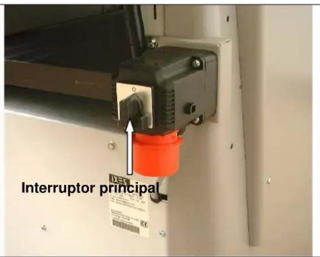
natural_image
Industrial conveyor belt system with directional arrows and labeled component '1' (no readable text or symbols)natural_image
Industrial machine with hand pressing a wooden board, no visible text or symbolsAjuste das juntas
natural_image
Person using a microscope to interact with a cylindrical device (no visible text or symbols)Fig. «L»

natural_image
Industrial robotic device with white housing and red control buttons, labeled arrows pointing to components (no readable text or symbols)Fig. «M»

Desbastar – Avanço
Fig. «N»
natural_image
Control panel with rotary knob, two switches (green and red), and a green circular indicator (no text or symbols visible)Fig. «O»
natural_image
Interior view of a mechanical assembly with chain links and gears (no visible text or symbols)
natural_image
Close-up of industrial machinery components with metallic and threaded metal parts, no visible text or symbolsnatural_image
Person operating a mechanical device in a workshop, with an arrow pointing to a component (no visible text or symbols)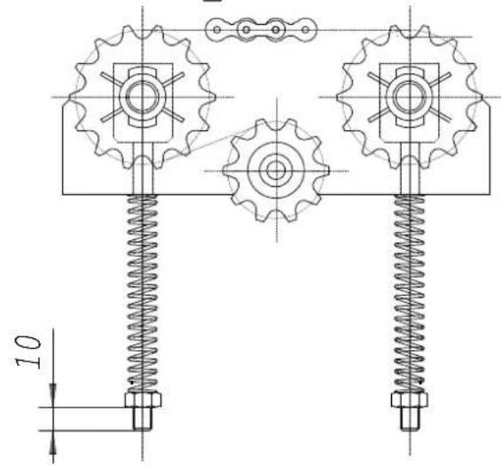
Fig. «S»

natural_image
Close-up of a mechanical assembly with metal components and a spring-loaded spring (no visible text or symbols)Mesa para aplainar
Fig. «T»
natural_image
Close-up of a mechanical component with a metallic bolt and pipe fitting, featuring an arrow pointing to a specific part (no text or symbols visible)Fig. «P»
natural_image
Technical cross-sectional diagram of a mechanical assembly (no text or labels)natural_image
Technical diagram of a mechanical assembly with cross-hatching and dimension lines (no readable text or symbols)
natural_image
Technical line drawing of a mechanical component with a cylindrical body and internal structure, showing a dimension arrow (no text or symbols)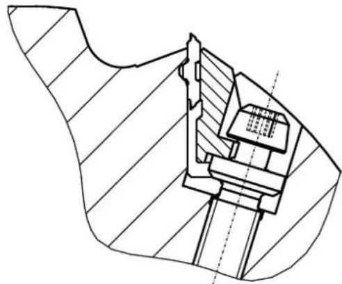
natural_image
Technical line drawing of a mechanical assembly with hatched areas and internal components (no text or symbols)
natural_image
Cross-sectional technical diagram of a mechanical assembly with no visible text or symbolsGünzburger Straße 69
D-89335 Ichenhausen
Ärade kund,
natural_image
Hand holding a tool interacting with a small mechanical component on a wooden surface (no text or symbols visible)Fig. "B"
natural_image
Close-up of a mechanical assembly with a numbered component (1) and directional arrows, no readable text or symbols present.Fig. "C"
natural_image
Close-up of a mechanical device with directional arrows indicating motion or movement, no visible text or symbols.Fig. "D"
natural_image
Hand operating a machine with a handle, showing blade and frame structure (no text or symbols visible)Fig. "E"
natural_image
Person operating a mechanical testing machine with a clamping tool (no visible text or symbols)Observera:
natural_image
Interior view of an industrial control panel with three buttons (green, red, yellow) and a switch (black), no visible text or symbols.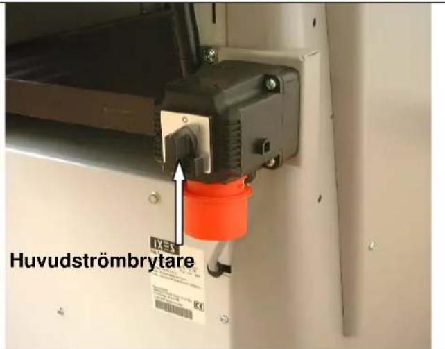
natural_image
Person using a microscope instrument to interact with a mechanical component (no visible text or symbols)Fig. "L"
natural_image
Industrial machine with white housing and black pipe, labeled arrows pointing to components (no readable text or symbols)Fig. "M"
natural_image
Close-up of hands operating a mechanical device with a curved arrow indicating rotation (no text or symbols visible)Planhyvling – matning
Fig. "N"
natural_image
Control panel with rotary knob, push buttons, and indicator lights (no text or symbols visible)Fig. "O"

natural_image
Interior view of a mechanical device with visible gears, springs, and tubing (no text or symbols)
natural_image
Close-up of industrial machinery components with metallic and threaded metal parts, no visible text or symbolsKilremsspänning
Fig. "P"
natural_image
Close-up of a mechanical assembly with a coiled spring and metal components (no visible text or symbols)Riktbordet
Fig. "T"
natural_image
Close-up of a mechanical component with a metallic bolt and pipe fitting, showing a white arrow pointing to a small hole (no text or symbols visible)Fig. "P"


natural_image
Technical cross-sectional diagram of a mechanical assembly (no text or labels)natural_image
Technical diagram of a mechanical assembly with cross-hatching and dimension lines (no readable text or symbols)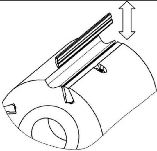
natural_image
Technical line drawing of a mechanical component with a cylindrical body and internal structure, showing a dimension arrow (no text or symbols)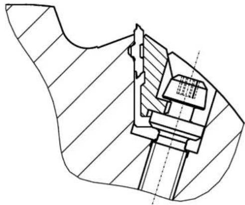
natural_image
Technical line drawing of a mechanical assembly with hatched sections and internal components (no text or symbols)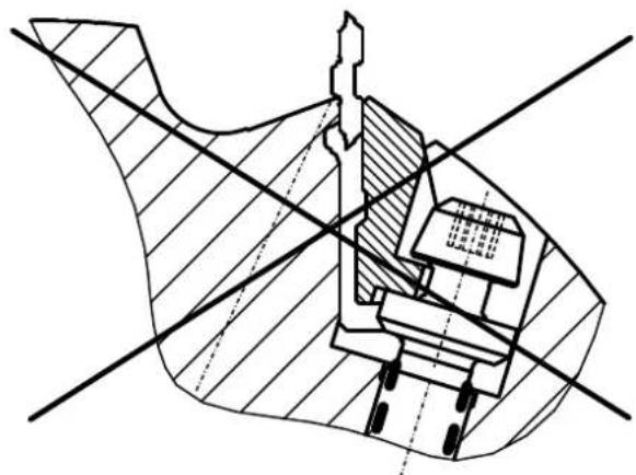
natural_image
Technical cross-sectional diagram of a mechanical assembly (no text or labels)Günzburger Straße 69
D-89335 Ichenhausen
Arvoisa asiakas,
Ottoteho P1 kW 4,0 5,0
Antoteho P2 kW 3,0 4,0
natural_image
Hand holding a tool interacting with a mechanical component (no visible text or symbols)Kuva "B"

natural_image
Close-up of a mechanical assembly with a tool and component, no visible text or symbolsKuva "C"

Kuva"D"
natural_image
Hand operating a machine with a metal tray and handle, no visible text or symbolsKuva "E"
natural_image
Person operating a mechanical testing machine with a clamping tool (no visible text or symbols)Huomio:
natural_image
Interior view of an industrial control panel with three buttons (black, green, red) and a central switch (no text or symbols visible)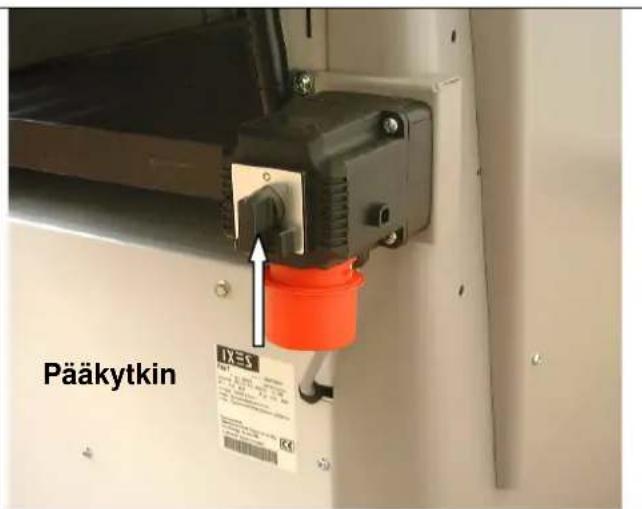
natural_image
Industrial machine with conveyor belt and pipe system, no visible text or symbolsSaumatus
Kuva "J"
natural_image
Industrial machine with wooden panel and hand interacting with a wooden block (no visible text or symbols)Sauman säätäminen
natural_image
Control panel with rotary knob, push buttons, and indicator lights (no text or symbols visible)Kuva "O"

natural_image
Interior view of a mechanical assembly with chains and gears (no visible text or symbols)
natural_image
Close-up of industrial machinery components with metallic and threaded metal parts, no visible text or symbolsnatural_image
Close-up of a mechanical assembly with a coiled spring and metal components (no visible text or symbols)natural_image
Close-up of a mechanical assembly with a bolt and pipe fitting (no visible text or symbols)Kuva "P"

natural_image
Technical drawing of a mechanical assembly with cross-hatching and dimension lines (no text or symbols)natural_image
Technical diagram of a mechanical assembly with cross-hatching and dimension lines (no readable text or symbols)
natural_image
Technical line drawing of a mechanical component with no visible text or symbols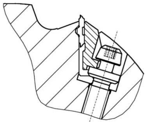
natural_image
Technical line drawing of a mechanical assembly with hatched sections and internal components (no text or symbols)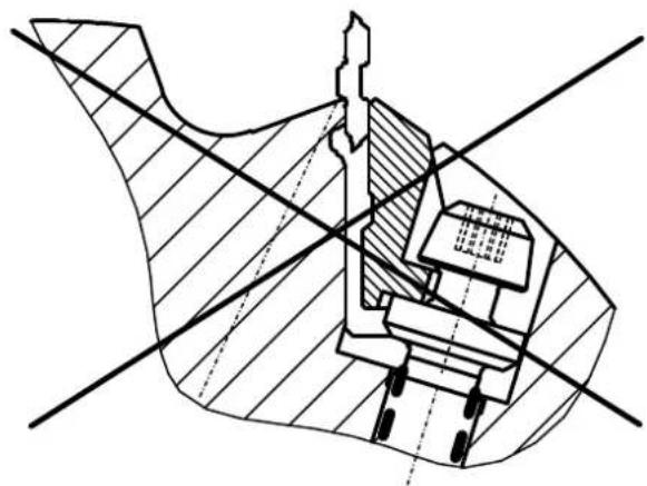
natural_image
Cross-sectional technical diagram of a mechanical assembly with hatched areas and intersecting lines (no text or labels)Günzburger Straße 69
D-89335 Ichenhausen / Tyskland
Kære kunde!
Ydelse P2 kW 3,0 4,0
Motoromdrejningstal o/min. 2800 2800
Driftsform S 6 / 40 % S6/40%
natural_image
Hand holding a tool near a mechanical component (no visible text or symbols)Fig. „B“

natural_image
Close-up of a mechanical assembly with a ruler and clamping tool, showing no visible text or symbolsFig. „C“

natural_image
Close-up of a mechanical device with directional arrows and label '2' (no readable text or symbols beyond labels)Fig. „D“
natural_image
Hand operating a machine with a handle, showing internal components and a wooden handle (no text or symbols visible)Fig. „E“
natural_image
Person adjusting a mechanical device with a tool, no visible text or symbolsAdvarsel:
natural_image
Interior view of an industrial control panel with three buttons (black, green, red) and a rotary knob (no text or symbols visible)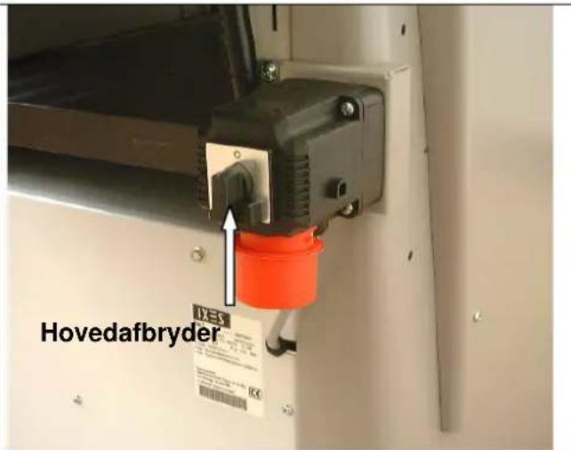
natural_image
Industrial machine with conveyor belt and pipe system, no visible text or symbolsnatural_image
Industrial machine with wooden board and hand interacting, no visible text or symbolsIndstilling af fuge
natural_image
Person interacting with a mechanical device, handling a black-and-white component (no visible text or symbols)Fig. „L“
natural_image
Industrial robotic device with white housing and red control buttons, labeled with arrows pointing to components (no readable text or symbols)Fig.,M"
natural_image
Close-up of hands operating a mechanical device with a rotating knob and handle (no visible text or symbols)natural_image
Interior view of an industrial control panel with rotary knob, switches, and indicator lights (no text or symbols visible)Fig. „O“

natural_image
Interior view of a mechanical assembly with chains and gears (no visible text or symbols)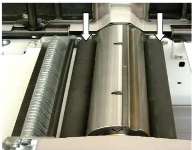
natural_image
Close-up of industrial machinery components with metallic and threaded metal parts, no visible text or symbolsSpænding af kilerem
Fig. „P“
natural_image
Person operating a mechanical device in a workshop, with an arrow pointing to a component (no visible text or symbols)
Fig. „S“

natural_image
Close-up of industrial machinery components including a metal sheet and threaded spring, with no visible text or symbols.natural_image
Close-up of a mechanical component with a metallic bolt and pipe fitting, showing a white arrow pointing to a small hole (no text or symbols visible)Fig. „P“


natural_image
Technical cross-sectional diagram of a mechanical assembly (no text or labels)natural_image
Technical line drawing of a mechanical assembly with cross-hatching and dimension lines (no text or symbols)
natural_image
Technical line drawing of a mechanical component with a cylindrical body and internal structure, showing a dimension arrow (no text or symbols)
natural_image
Technical line drawing of a mechanical assembly with hatched sections and internal components (no text or symbols)
natural_image
Cross-sectional technical diagram of a mechanical assembly with hatched areas and intersecting lines (no text or labels)Günzburger Straße 69
D-89335 Ichenhausen
Kjære kunde!
INNHOLDET I LEVERANSEN
TEKNISKE DATA
MONTERING
OPPSTILLING OG JUSTERING
ELEKTRISK TILKOPLING
KOPLINGSSKJEMA 380-420V
IDRIFTSETTElse
INNSTILLING AV FUGEN
JUSTERING AV POSISJONSANVISER
TYKKELSESH∅VLING - MATING
VEDLIKEHOLD
H∅VELBLAD
FEILS∅KING
RESERVEDELLISTE
EF-OVERENSSTEMMELSESERKLÆRING
GARANTI
natural_image
Hand holding a tool near a mechanical component (no visible text or symbols)Bilde «B»

natural_image
Close-up of a mechanical assembly with a tool and component, no visible text or symbolsBilde «C»

Bilde «D»
→ Klem fast avretteranslaget med de to eksenterarmene (3).
Avretteranslaget kan stilles maks 410 mm over høvelbredden.
Bilde «E»
natural_image
Hand operating a machine with a metal tray and handle, no visible text or symbolsBilde «E»
Bilde «E1»
natural_image
Person using a mechanical clamp to adjust or install a large cylindrical component (no visible text or symbols)natural_image
Interior view of an industrial control panel with three switches (labeled 1, 2, 3) and a green indicator light (no text or symbols beyond labels)
natural_image
Industrial machine with conveyor belt and pipe system, no visible text or symbols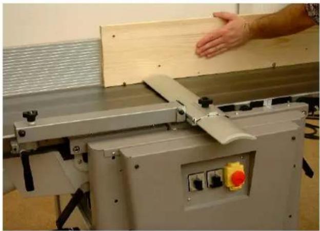
natural_image
Industrial machine with wooden panel and hand interacting with a hand (no visible text or symbols)natural_image
Person holding a black cylindrical object through a mechanical device (no visible text or symbols)Bilde «L»
natural_image
Industrial robotic device with white housing and red control buttons, labeled '1' arrows pointing to components (no readable text or symbols)Bilde «M»

natural_image
Control panel with rotary knob, two switches (green and red), and a green circular indicator (no text or symbols visible)Bilde «O»
natural_image
Interior view of a mechanical assembly with chains and gears (no visible text or symbols)
natural_image
Close-up of industrial mechanical components with metallic and threaded parts, no visible text or symbolsnatural_image
Person operating a mechanical device in a workshop, with an arrow pointing to a component (no visible text or symbols)
Bilde «S»

natural_image
Close-up of a mechanical assembly with metal components and a spring-loaded spring (no visible text or symbols)Avretterbord Bilde «T»
natural_image
Close-up of a mechanical component with a metallic bolt and pipe fitting, showing a white arrow pointing to a specific part (no text or symbols visible)Bilde «P»
natural_image
Technical drawing of a mechanical assembly with cross-hatching and dimension lines (no text or symbols)natural_image
Technical diagram of a mechanical assembly with cross-sectional view and hatched fill (no text or labels)
natural_image
Technical line drawing of a mechanical component with a cylindrical body and internal structure, showing a dimension arrow (no text or symbols)
natural_image
Technical line drawing of a mechanical assembly with hatched areas and internal components (no text or symbols)
natural_image
Technical cross-sectional diagram of a mechanical assembly (no text or labels)Günzburger Straße 69
D-89335 Ichenhausen
natural_image
Hand holding a tool interacting with a mechanical component (no visible text or symbols)Фуговальный упор
Рис. „В“
natural_image
Close-up of a mechanical assembly with metal components and a numbered annotation (1), no readable text or symbols present.Рис. „С“
natural_image
Close-up of a mechanical device with directional arrows and label '2' (no readable text or symbols beyond labels)Рис. „D“
natural_image
Hand operating a machine with a handle, showing blade and frame structure (no text or symbols visible)Рис. „E“
natural_image
Person using a mechanical clamp to adjust or install a large cylindrical component (no visible text or symbols)Внимание:
natural_image
Interior view of an industrial control panel with two switches and a color-coded button (no text or symbols visible)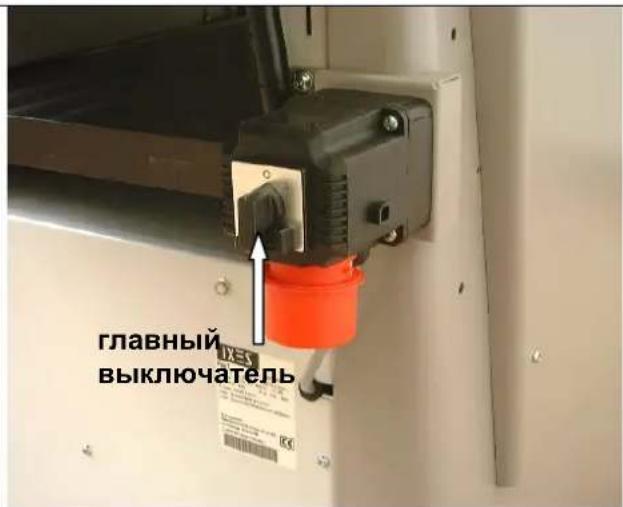
natural_image
Industrial machine with conveyor belt and pipe system, no visible text or symbols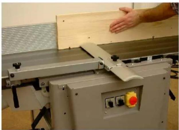
natural_image
Industrial machine with hand operating a wooden board, no visible text or symbolsУстановка фуги
natural_image
Person interacting with a mechanical device, handling a black and white component (no visible text or symbols)Abb. "L"
natural_image
Industrial robotic device with white housing and red control buttons, labeled arrows pointing to components (no readable text or symbols)Abb. "M"

natural_image
Close-up of hands operating a mechanical device with a rotating knob and adjustment arrows (no text or symbols visible)natural_image
Control panel with rotary knob, push buttons, and indicator lights (no text or symbols visible)Рис. „О“

natural_image
Interior view of a mechanical device with visible gears, springs, and housing (no text or symbols)
natural_image
Close-up of industrial machinery components with metallic and threaded metal parts, no visible text or symbolsnatural_image
Close-up of a mechanical assembly with a coiled spring and threaded rod (no visible text or symbols)natural_image
Close-up of mechanical components with a white arrow pointing to a bolted component (no visible text or symbols)Рис. „Р“
flowchart
graph TD
    A["Device with parts 1 and 4"] --> B["Component 1"]
    B --> C["Component 4"]
    C --> D["Return to Component 4"]
    style A fill:#f9f,stroke:#333
    style B fill:#ccf,stroke:#333
    style C fill:#cfc,stroke:#333

natural_image
Technical cross-sectional diagram of a mechanical assembly (no text or labels)natural_image
Technical diagram of a mechanical assembly with cross-sectional view and hatched fill (no text or labels)
natural_image
Technical line drawing of a mechanical component with a cylindrical body and internal structure, showing a dimension arrow (no text or symbols)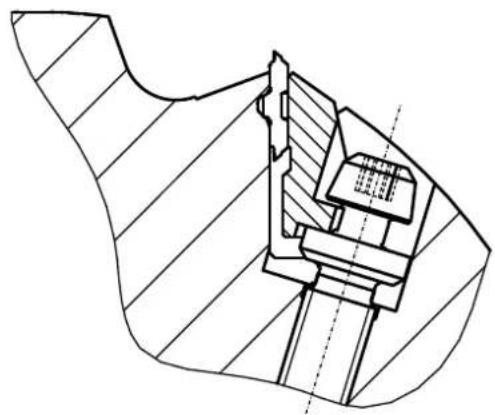
natural_image
Technical line drawing of a mechanical assembly with hatched sections and internal components (no text or symbols)