BCJ900 - Plane SCHEPPACH - Free user manual and instructions
Find the device manual for free BCJ900 SCHEPPACH in PDF.

| Product Type | Biscuit joiner (flat dowel cutter) |
| Brand | Scheppach |
| Model | BCJ900 |
| Power Consumption | 900 W |
| Voltage / Frequency | 230-240 V~ / 50 Hz |
| No-load Speed | 12,000 min⁻¹ |
| Cutting Disc Diameter | 100 mm |
| Disc Bore | 22 mm |
| Max. Groove Depth | 1.8 mm |
| Groove Width | 4 mm |
| Weight | Approx. 3 kg |
| Protection Class | II (double insulation) |
| Spindle Dimensions | M10 |
| Sound Pressure Level | 87 dB(A) |
| Sound Power Level | 98 dB(A) |
| Vibration Level | 2.695 m/s² |
| Dust Bag Capacity | With zipper, easy emptying |
| Adjustments | Cutting depth, angle (0-67.5° in steps), height stop |
| Included Accessories | Dust bag, suction adapter, adjustable wrench, height stop, assembly biscuits (No. 0, 10, 20) |
| Maintenance | Disconnect before cleaning; clean with damp cloth; empty dust bag |
| Wear Parts | Cutting disc, carbon brushes |
| Warranty | Statutory, defective parts replaced free of charge (excluding labor) |
Frequently Asked Questions - BCJ900 SCHEPPACH
User questions about BCJ900 SCHEPPACH
0 question about this device. Answer the ones you know or ask your own.
Ask a new question about this device
Download the instructions for your Plane in PDF format for free! Find your manual BCJ900 - SCHEPPACH and take your electronic device back in hand. On this page are published all the documents necessary for the use of your device. BCJ900 by SCHEPPACH.
USER MANUAL BCJ900 SCHEPPACH
natural_image
Exterior view of a Scherpack electric shaver with a black bandage and label (no additional text or symbols visible)
BCJ900
| DE | FlachdübelfräseOriginalbetriebsanleitung | 5 |
| GB | Biscuit joinerTranslation of original instruction manual | 20 |
| FR | LamelleuseTraduction des instructions d'origine | 32 |

natural_image
Technical line drawing of a mechanical device with two views: top shows internal components, bottom shows assembly or mounting (no text or symbols)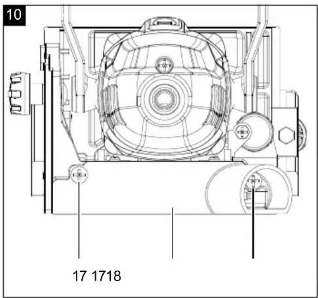
natural_image
Technical line drawing of a mechanical assembly with gears and components (no text or symbols)Günzburger Straße 69
D-89335 Ichenhausen
Verehrter Kunde
natural_image
Technical line drawing of three mechanical components with no visible text or symbolsnatural_image
Technical line drawing of three mechanical components with no visible text or symbolsnatural_image
Technical line drawing of a mechanical device with an inset showing a corner joint detail (no text or symbols present)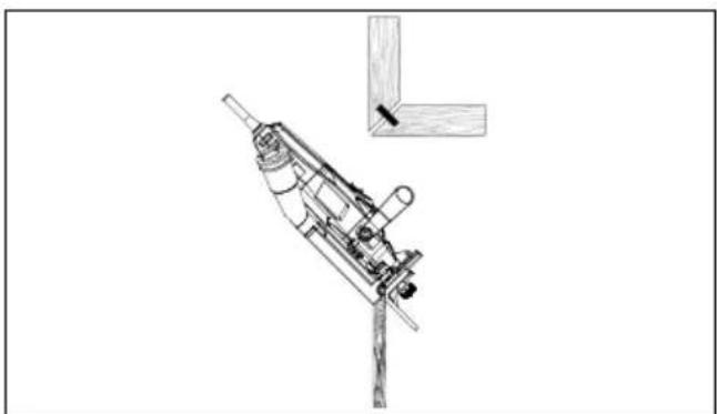
natural_image
Technical line drawing of a mechanical device with a bracket and mounting base (no text or symbols)natural_image
Technical line drawing of a mechanical device with no visible text or symbols
natural_image
Technical line drawing of a mechanical device with no visible text or symbolsnatural_image
Technical line drawings of mechanical components, including a drill bit and a tool assembly (no text or symbols)natural_image
Technical line drawing of a mechanical assembly with two views of a tool, no text or symbols presentHomepage: https://www.scheppach.com/de/service
Explanation of the symbols on the device
Symbols are used in this manual to draw your attention to potential hazards. The safety symbols and the accompanying explanations must be fully understood. The warnings themselves will not rectify a hazard and cannot replace proper accident prevention measures.
 | Warning - read the instruction manual to reduce the risk of injury. |
 | Wear hearing protection. Excessive noise can result in a loss of hearing. |
 | Wear a dust protection mask. When machining wood and other materials, harmful dust may be generated. Do not machine material containing asbestos! |
 | Wear eye protection. Sparks created during work or fragments, chippings and dust ejected by the device can case sight loss. |
 | Protection class II |
| ⚠ Attention! | We have marked points in these operating instructions that impact your safety with this symbol. |
 | The product complies with the applicable European directives. |
Table of contents: Page:
- Introduction....22
- Device description (fig. 1-13)....22
- Scope of delivery (fig. 2)....22
- Proper use 23
- General safety information 23
- Residual risks 25
- Technical data....25
- Unpacking 26
- Assembly 26
- Start up 26
- Working instructions....27
- Common joints....27
- Electrical connection 29
- Cleaning....29
- Storage 29
- Maintenance (Fig. 10 - 13)....29
- Disposal and recycling....30
- Troubleshooting 31
- Declaration of conformity 47
1. Introduction
Manufacturer:
Scheppach GmbH
Günzburger Straße 69
D-89335 Ichenhausen
Dear Customer
We hope your new tool brings you much enjoyment and success.
Note:
In accordance with the applicable product liability laws, the manufacturer of this device assumes no liability for damage to the device or caused by the device arising from:
- Improper handling,
• Non-compliance with the operating manual,
• Repairs carried out by third parties, unauthorised specialists.
• Installing and replacing non-original spare parts
• Application other than specified - Failure of the electrical system in the event of the electrical regulations and VDE provisions 0100, DIN 57113 / VDE0113 not being observed
Please consider:
Read through the complete text in the operating manual before installing and commissioning the device.
The operating manual is intended to help the user to become familiar with the machine and take advantage of its application possibilities in accordance with the recommendations.
The operating manual includes important instructions for safe, proper and economic operation of the device, for avoiding danger, for minimising repair costs and downtimes, and for increasing the reliability and extending the service life of the device.
In addition to the safety instructions in this operating manual, you must also observe the regulations applicable to the operation of the device in your country.
Keep the operating manual package with the machine at all times and store it in a plastic cover to protect it from dirt and moisture. They must be read and carefully observed by all operating personnel before starting the work.
The device may only be used by personnel who have been trained to use it and who have been instructed with respect to the associated hazards.
The required minimum age must be observed.
In addition to the safety instructions in this operating manual and the separate regulations of your country, the generally recognised technical rules relating to the operation of such machines must also be observed.
We accept no liability for accidents or damage that occur due to a failure to observe this manual and the safety instructions.
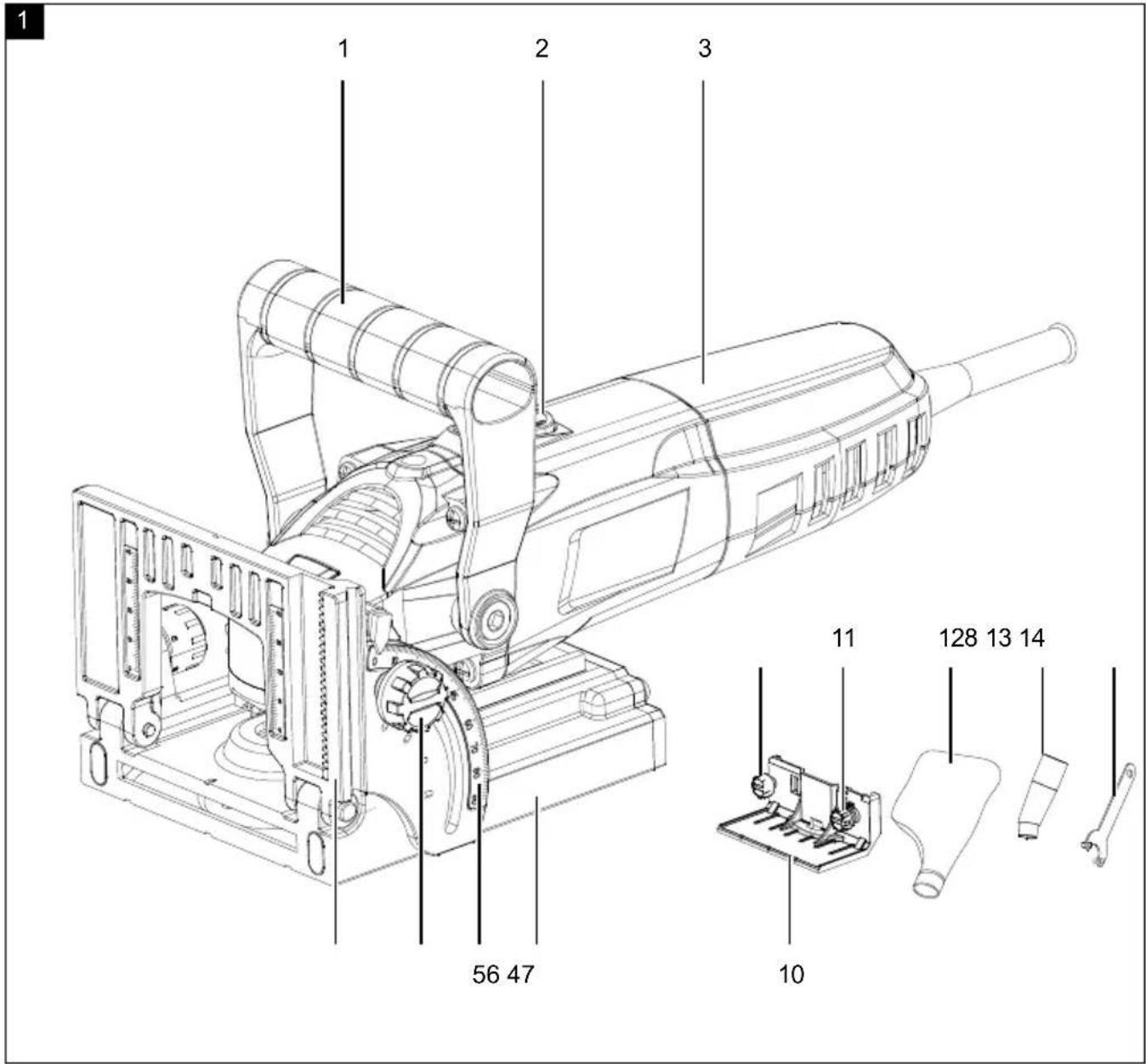
2. Device description (fig. 1-13)
- Additional grip
- On/off switch
- Main handle
- Protective device
- Angle scale
- Locking screw for angle adjustment
- Angular stop
- Locking screw for height adjustment
- Viewing window
- Height stop
- Adjusting screw for height adjustment
- Dust bag
- Extraction adapter
- Face spanner
- Extraction port
- Depth adjustment knob
- Screw
- Cover
- Spindle lock
- External flange
- Side milling cutter
- Internal flange
- Spindle
- Lock nut
- Depth adjustment screw
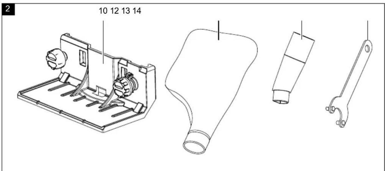
3. Scope of delivery (fig. 2)
- Biscuit jointer
- Suction adapter (13)
- Dust bag (12)
- Face spanner (14)
- Height stop (10)
• 20x no. 0 biscuits (not shown)
• 20x no. 10 biscuits (not shown)
• 20x no. 20 biscuits (not shown) - Operating manual
4. Proper use
The biscuit jointer is suitable for routing grooves for biscuit joints in chipboard, hardwood or softwood, plywood or fibreboard.
The machine may only be used in the intended manner.
Any use beyond this is improper. The user/operator, not the manufacturer, is responsible for damages or injuries of any type resulting from this.
An element of the intended use is also the observance of the safety instructions, as well as the assembly instructions and operating information in the operating manual.
Persons who operate and maintain the machine must be familiar with it and must be informed about potential dangers.
In addition, the applicable accident prevention regulations must be strictly observed.
Other general occupational health and safety-related rules and regulations must be observed.
The liability of the manufacturer and resulting damages are excluded in the event of modifications of the machine.
The machine may only be operated with original parts and original accessories from the manufacturer.
The safety, operating and maintenance specifications of the manufacturer, as well as the dimensions specified in the technical data, must be observed.
Please observe that our equipment was not designed with the intention of use for commercial or industrial purposes. We assume no guarantee if the equipment is used in commercial or industrial applications, or for equivalent work.
The device is intended for use by adults. Children over the age of 16 may use the tool except under supervision. The manufacturer is not liable for damage caused by an improper use or incorrect operation of this device.
5. General safety information
General power tool safety warnings
WARNING!
Read all safety warnings, instructions, illustrations and specifications provided with this power tool.
Failure to follow all instructions listed below may result in electric shock, fire and/or serious injury.
Save all warnings and instructions for future reference.
The term “power tool” in the warnings refers to your mains-operated (corded) power tool or battery-operated (cordless) power tool.
1. Workplace safety
a) Keep work area clean and well lit. Cluttered or dark areas invite accidents.
b) Do not operate power tools in explosive atmospheres, such as in the presence of flammable liquids, gases or dust. Power tools create sparks which may ignite the dust or fumes.
c) Keep children and bystanders away while operating a power tool. Distractions can cause you to lose control.
2. Electrical safety
a) Power tool plugs must match the outlet. Never modify the plug in any way. Do not use any adapter plugs with earthed (grounded) power tools. Unmodified plugs and matching outlets will reduce risk of electric shock.
b) Avoid body contact with earthed or grounded surfaces, such as pipes, radiators, ranges and refrigerators. There is an increased risk of electric shock if your body is earthed or grounded.
c) Do not expose power tools to rain or wet conditions. Water entering a power tool will increase the risk of electric shock.
d) Do not abuse the cord. Never use the cord for carrying, pulling or unplugging the power tool. Keep cord away from heat, oil, sharp edges or moving parts. Damaged or entangled cords increase the risk of electric shock.
e) When operating a power tool outdoors, use an extension cord suitable for outdoor use. Use of a cord suitable for outdoor use reduces the risk of electric shock.
f) If operating a power tool in a damp location is unavoidable, use a residual current device (RCD) protected supply. Use of an RCD reduces the risk of electric shock.
3. Personal safety
a) Stay alert, watch what you are doing and use common sense when operating a power tool. Do not use a power tool while you are tired or under the influence of drugs, alcohol or medication. A moment of inattention while operating power tools may result in serious personal injury.
b) Use personal protective equipment. Always wear eye protection. Protective equipment such as a dust mask, non-skid safety shoes, hard hat or hearing protection used for appropriate conditions will reduce personal injuries.
c) Prevent unintentional starting. Ensure the switch is in the off-position before connecting to power source and/or battery pack, picking up or carrying the tool. Carrying power tools with your finger on the switch or energising power tools that have the switch on invites accidents.
d) Remove any adjusting key or wrench before turning the power tool on. A wrench or a key left attached to a rotating part of the power tool may result in personal injury.
e) Do not overreach. Keep proper footing and balance at all times. This enables better control of the power tool in unexpected situations.
f) Dress properly. Do not wear loose clothing or jewellery. Keep your hair and clothing away from moving parts. Loose clothes, jewellery or long hair can be caught in moving parts.
g) If devices are provided for the connection of dust extraction and collection facilities, ensure these are connected and properly used. Use of dust collection can reduce dust-related hazards.
h) Do not let familiarity gained from frequent use of tools allow you to become complacent and ignore tool safety principles. A careless action can cause severe injury within a fraction of a second.
- Power tool use and care
a) Do not force the power tool. Use the correct power tool for your application. The correct power tool will do the job better and safer at the rate for which it was designed.
b) Do not use the power tool if the switch does not turn it on and off. Any power tool that cannot be controlled with the switch is dangerous and must be repaired.
c) Disconnect the plug from the power source and/or remove the battery pack, if detachable, from the power tool before making any adjustments, changing accessories, or storing power tools. Such preventive safety measures reduce the risk of starting the power tool accidentally.
d) Store idle power tools out of the reach of children and do not allow persons unfamiliar with the power tool or these instructions to operate the power tool. Power tools are dangerous in the hands of untrained users.
e) Maintain power tools and accessories. Check for misalignment or binding of moving parts, breakage of parts and any other condition that may affect the power tool's operation. If damaged, have the power tool repaired before use.
Many accidents are caused by poorly maintained power tools.
f) Keep cutting tools sharp and clean. Properly maintained cutting tools with sharp cutting edges are less likely to bind and are easier to control.
g) Use the power tool, accessories and tool bits etc. in accordance with these instructions, taking into account the working conditions and the work to be performed. Use of the power tool for operations different from those intended could result in a hazardous situation.
h) Keep handles and grasping surfaces dry, clean and free from oil and grease. Slippery handles and grasping surfaces do not allow for safe handling and control of the tool in unexpected situations.
- Service
a) Have your power tool serviced by a qualified repair person using only identical replacement parts. This will ensure that the safety of the power tool is maintained.
ATTENTION!
This power tool generates an electromagnetic field during operation. This field can impair active or passive medical implants under certain conditions. In order to prevent the risk of serious or deadly injuries, we recommend that persons with medical implants consult with their physician and the manufacturer of the medical implant prior to operating the machine.
Safety instructions for biscuit jointers
a) Side milling cutters must be designed for the speed indicated on the electric tool as a minimum. Side milling cutters running at speeds higher than their rated speed can fly apart and cause injuries.
b) Always use the protective cover. A protective cover protects the user from broken off parts of the side milling cutter and from accidental contact with the cutter.
c) Hold the electric tool by the insulated gripping surfaces, as the cutter can hit its own mains cable. Contact with a live power line can also electrify metal device parts and lead to an electric shock.
d) Always use side milling cutters of the correct size and with a matching mounting hole. Side milling cutters that do not fit with the mounting parts of the cutter will run out-of-centre and result in a loss of control.
e) Only guide the electric tool against the workpiece when switched on. Otherwise there is a risk of kick-back if the tool attachment gets caught in the workpiece. If you switch on the electric tool while the cutting disc is touching the workpiece, kick-back will occur.
f) Do not place your hands in the cutting area or on the cutter. Hold the additional grip with your other hand. If both hands hold the cutter, they cannot be injured by the cutter.
g) Never mill over metal objects, nails or screws. The cutter can be damaged and this can lead to increased vibrations.
h) Use the appropriate detection devices in order to detect hidden supply lines or consult the local utility company. Contact with electrical lines can result in fire and electric shock. Penetrating a water pipe causes property damage or may cause an electric shock.
i) Hold the electrical tool firmly with both hands and ensure firm footing. It is safer to guide the electrical tool with two hands.
j) Secure the workpiece. A workpiece held with a clamping device or vice is held more securely than with your hand.
k) Wait until the electrical tool has come to a standstill before setting it down. The tool attachment can get caught and this can lead to loss of control over the electric tool.
I) Use the additional grips if these are supplied with the electric tool. Loss of control can lead to injuries.
6. Residual risks
The machine has been built according to the state-of-the-art and the recognised technical safety requirements. However, individual residual risks can arise during operation.
• Health hazard due to electrical power, with the use of improper electrical connection cables.
• Furthermore, despite all precautions having been met, some non-obvious residual risks may still remain.
- Residual risks can be minimised if the "Safety information" and the "Proper use" together with the operating manual as a whole are observed.
- Avoid accidental starting of the machine: the operating button may not be pressed when inserting the plug in an outlet. Use the tool attachment that is recommended in this operating manual. This is how to ensure that your machine provides optimum performance.
- Keep your hands away from the work area, when the machine is in operation.
7. Technical data
| Motor 230 - 240 V~ / 50 Hz |
| Power consumption 900 W |
| Idle speed 12000 min |
| Side milling cutter ∅ 100 mm |
| Spindle size M10 |
| Cutting disc bore ∅ 22 mm |
| Groove depth max. 18 mm |
| Groove width 4 mm |
| Protection class 2 |
| Weight approx. 3 kg |
Technical changes reserved!
Noise and vibration
⚠ Warning: Noise can have serious effects on your health. If the machine noise exceeds 85 dB, please wear suitable hearing protection.
Information about noise level measured in accordance with EN 60745
Noise data
| Sound power level L_WA | 98 dB |
| Sound pressure level L_pA | 87 dB |
| Uncertainty K_wa/pA | 3 dB |
Vibration parameters
Vibration value per EN 60745
| Vibration a_h | 2.695 m/s ^2 |
| Uncertainty K_h | 1.5 m/s ^2 |
8. Unpacking
- Open the packaging and carefully remove the device.
- Remove the packaging material, as well as the packaging and transport safety devices (if present).
- Check whether the scope of delivery is complete.
- Check the device and accessory parts for transport damage. In the event of complaints the carrier must be informed immediately. Later claims will not be recognised.
- If possible, keep the packaging until the expiry of the warranty period.
- Familiarise yourself with the product by means of the operating instructions before using for the first time.
- With accessories as well as wearing parts and replacement parts use only original parts. Replacement parts can be obtained from your dealer.
- When ordering please provide our article number as well as type and year of manufacture for your equipment.
⚠ WARNING!
The device and the packaging material are not children's toys! Do not let children play with plastic bags, films or small parts! There is a danger of choking or suffocating!
9. Assembly
Warning!
Always pull out the mains plug before carrying out adjustments on the device.
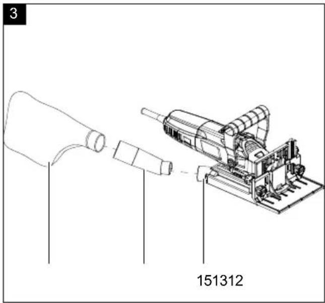
Fitting the dust bag (Fig. 3)
- Insert the suction adapter (13) into the suction port (15) of the device.
- Squeeze the clip of the dust bag (12) and place it on the suction adapter (13).
NOTE:
An external dust extraction device can be connected to the suction adapter (13).
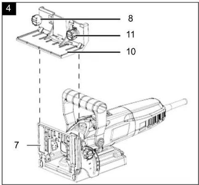
Fitting/removing the height stop (Fig. 4)
- Loosen the locking screw for the height stop (8).
- Place the height stop (10) onto the angle stop (7) from above.
- Turn the height stop adjustment screw (11) anti-clockwise to move the height stop (10) downwards.
Attention!
If resistance occurs during assembly, remove the height stop (10) and try again.
• Disassembly takes place in reverse order.
10. Start up
⚠ Attention!
Always make sure the device is fully assembled before commissioning!
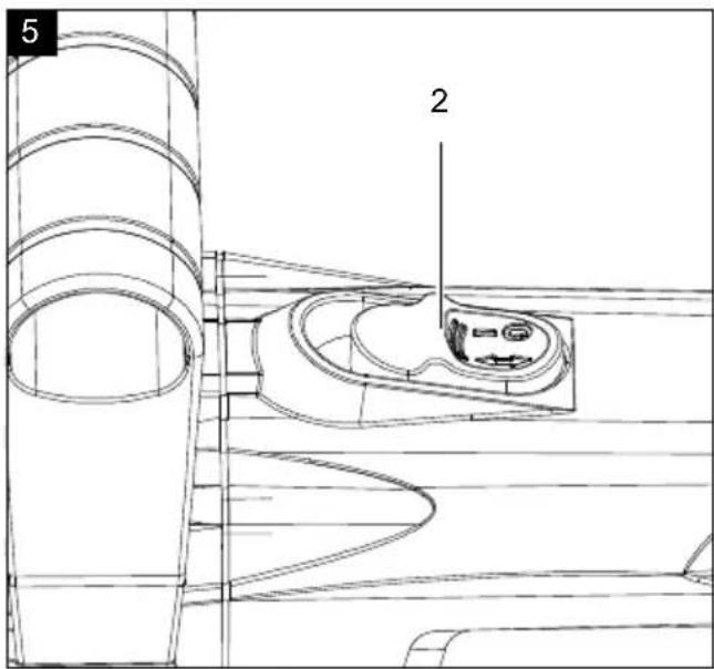
Switching on and off (Fig. 5)
- Switching on: Press down the rear part of the on/off switch (2) and slide it forward.
- Continuous operation: Press down the rear part of the ON/OFF switch (2) and slide it forward. Then press down the front part of the ON/OFF switch (2) until it latches into place.
- Switching off: Press the rear part of the ON/OFF switch (2) so that it jumps back to the off position.
Adjusting the size of the biscuit groove (Fig. 6)
- Turn the depth adjustment knob (16) until the desired biscuit groove size is aligned with the marking.
Position Biscuit Cutting depth
| 0 No. 0 8 mm | |
| 10 No. 10 10 mm | |
| 20 No. 20 12.3 mm | |
| S Simplex 13 mm | |
| D Duplex | 14,7 |
| Max. | - 18 mm |
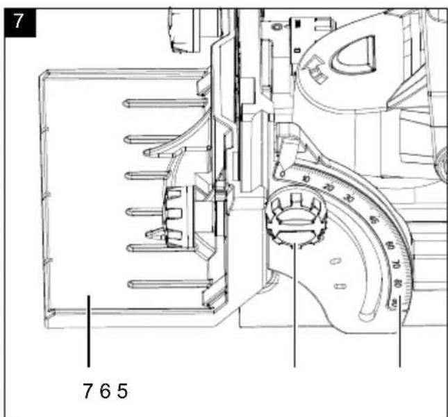
Setting the angle (Fig. 7)
- Loosen the locking screw for the angle setting (6).
- Use the angle scale (5) to set the required angle.
- Re-tighten the locking screw for the angle setting (6).
NOTE:
The angle stop (7) has 4 detent positions for 0^ , 22.5^ , 45^ and 67.5^ . The angle stop (7) engages at these angles to facilitate adjustment.
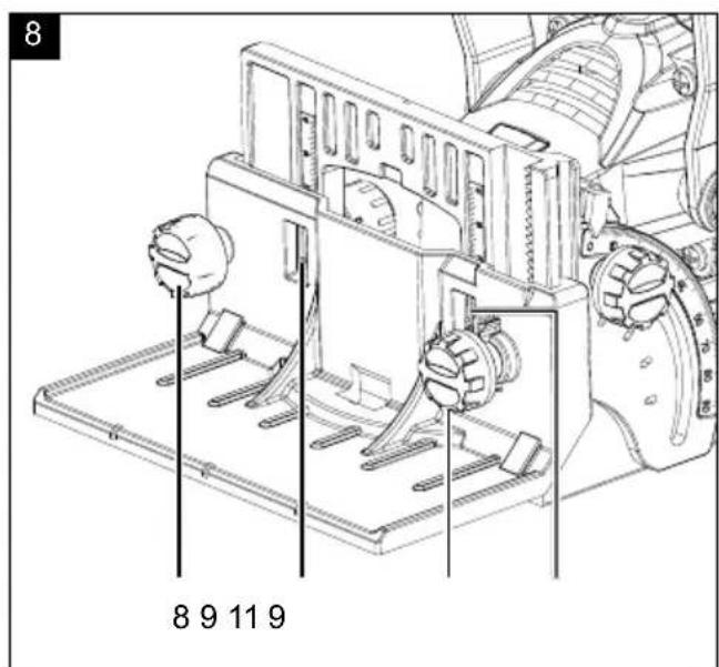
Adjusting the height stop (Fig. 8)
- Loosen the locking screw for the height stop (8).
-
Turn the adjusting screw for the height stop (11) clockwise to increase the height of the stop.
-
Turn the height stop adjustment screw (11) anti-clockwise to reduce the stop height.
- Set the desired height. The height set can be read off the viewing window (9).
- Tighten the locking screw for the height stop (8).
11. Working instructions
- The device must always be held with both hands. Hold the main grip (3) with one hand and the additional grip (1) with the other hand.
- Do not apply the cutting disc (21) to the workpiece until full speed has been reached.
- Select the appropriate size of biscuit to suit the thickness of the material:
Biscuit size Material thickness
| 0 8 - 12 mm |
| 10 12 - 15 mm |
| 20 > 15 mm |
12. Common joints
Corner joint with angle stop (7) / with height stop (10)
natural_image
Technical line drawing of three mechanical components with no visible text or symbolsMitre joint with angle stop (7) / with height stop (10)
NOTE:
If the material has a thickness of > 25 mm, mill 2 grooves one above the other. This doubles the stability of the connection.
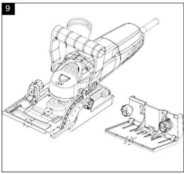
- Mark the centre of each groove on the material.
- Adjust the size of the biscuit with the depth adjustment knob (16).
• Fit/remove the height stop (10) as required. - Set the height stop (10) and the angle stop (7) as required.
- Use the centre mark to align the device with the workpiece (Fig. 9).
- Switch the device on.
- Push the device forward to mill the groove.
- If necessary, repeat the steps to mill more grooves.
natural_image
Technical line drawing of three mechanical components with no visible text or symbols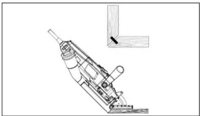
natural_image
Technical line drawing of a mechanical device with a small inset showing a wooden bracket detail (no text or symbols)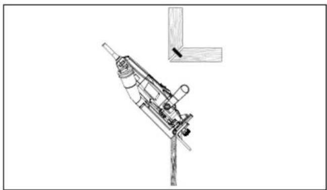
natural_image
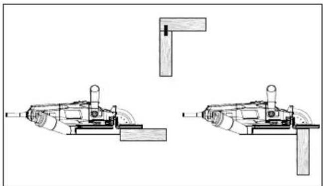
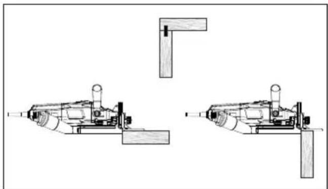
Technical line drawing of a mechanical device with a bracket and pin (no text or symbols)Butt joint with angle stop (7) / with height stop (10)
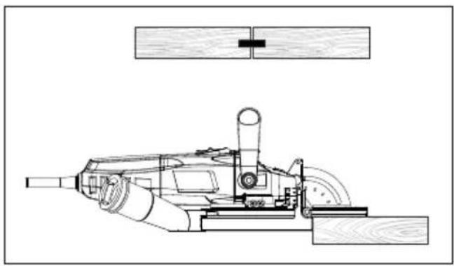
natural_image
Technical line drawing of a mechanical device with no visible text or symbols
natural_image
Technical line drawing of a mechanical device with no visible text or symbolsFrame connection with angle stop (7)
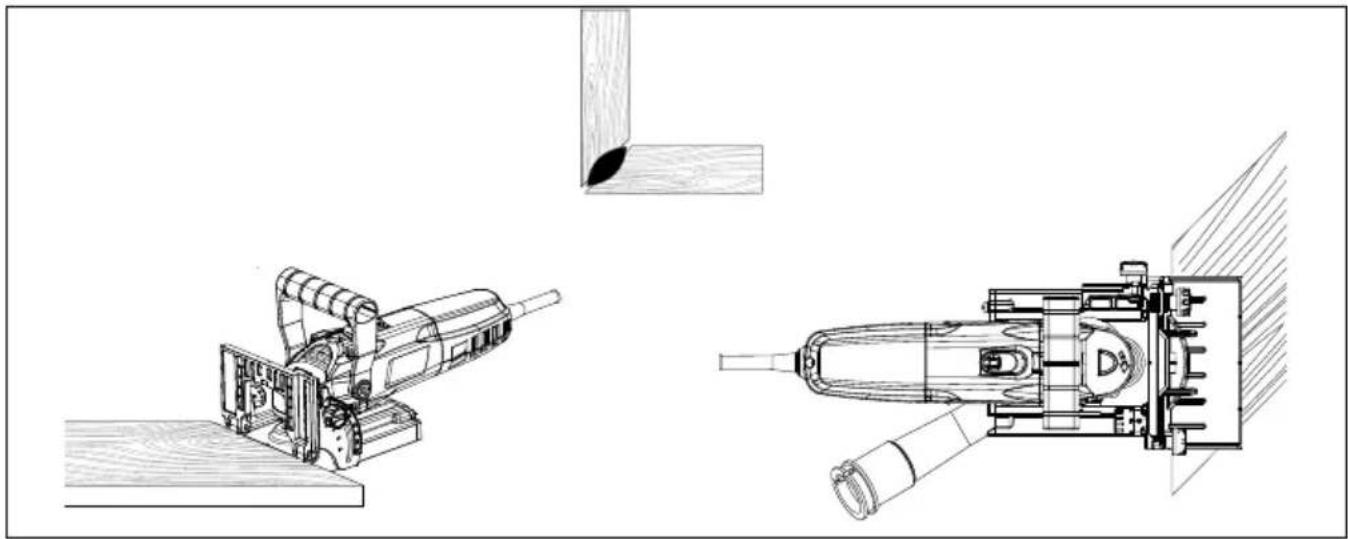
natural_image
Technical line drawings of mechanical components, including a cutting tool and a flat tool assembly (no text or symbols)T-connection with angle stop (7)
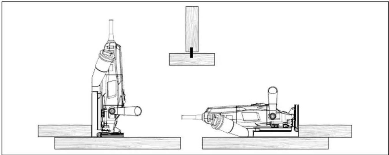
natural_image
Technical line drawing of a mechanical assembly with two views of a tool, no text or symbols present13. Electrical connection
The electrical motor installed is connected and ready for operation. The connection complies with the applicable VDE and DIN provisions.
The customer's mains connection as well as the extension cable used must also comply with these regulations.
Damaged electrical connection cable
The insulation on electrical connection cables is often damaged.
This may have the following causes:
- Pressure points, where connection cables are passed through windows or doors.
- Kinks where the connection cable has been improperly fastened or routed.
- Places where the connection cables have been cut due to being driven over.
• Insulation damage due to being ripped out of the wall outlet. - Cracks due to the insulation ageing.
Such damaged electrical connection cables must not be used and are life-threatening due to the insulation damage.
Check the electrical connection cables for damage regularly. Ensure that the connection cables are disconnected from electrical power when checking for damage.
Electrical connection cables must comply with the applicable VDE and DIN provisions. Only use connection cables of the same designation.
The printing of the type designation on the connection cable is mandatory.
For single-phase AC motors, we recommend a fuse rating of C 16A or K 16A for machines with a high starting current (from 3000 watts)!
Connection type X
If the mains connection cable of this device is damaged, it must be replaced by a special connection cable which can be obtained from the manufacturer or its service department.
14. Cleaning
Danger!
Pull out the mains plug before carrying out any cleaning work.
- Keep protective devices, air vents and the motor housing as free of dust and dirt as possible. Rub the device clean with a clean cloth or blow it off with compressed air at low pressure.
• We recommend that you clean the device directly after every use. - Clean the device at regular intervals using a damp cloth and a little soft soap. Do not use any cleaning products or solvents; they could attack the plastic parts of the device. Make sure that no water can penetrate the device interior. Water entering a power tool will increase the risk of electric shock.
Emptying the dust bag
- When the dust bag (12) is full, open the zip at the back and empty it.
- Close the zip again.
15. Storage
Store the device and its accessories in a dark, dry and frost-free place that is inaccessible to children. The optimum storage temperature lies between 5 and 30 °C. Store the power tool in its original packaging. Cover the power tool to protect it from dust or moisture. Store the operating manual with the power tool.
16. Maintenance (Fig. 10 - 13)
Danger!
Pull out the mains plug before carrying out any maintenance work.
Replacing the side milling cutter (Fig. 10 - 12)
- Loosen the screws (17) on the back of the cover (18) (Fig. 10).
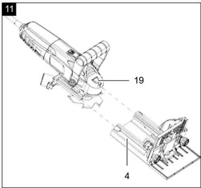
• Pull the main unit off the protective device (4) (Fig. 11). - Press and hold the spindle lock (19).
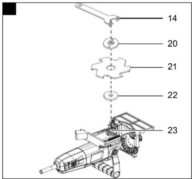
- Loosen the outer flange (20) anti-clockwise from the spindle (23) using the face spanner (14) (Fig. 12).
- Remove the outer flange (20) and the side milling cutter (21).
- Place the new side milling cutter (21) on the inner flange (22).
Attention!
There is a rotation direction arrow on the cutting disc (21). Make sure that the direction of rotation arrow of the cutting disc (21) is aligned with the arrow on the product.
- Place the outer flange (20) on the side milling cutter (21) and screw it tight with the face spanner (14).
Attention!
Make sure that the flat side of the outer flange (20) faces upwards.
- Connect the main unit to the protective device (4) (Fig. 11).
- Tighten the screws (17) on the back of the cover (18) (Fig. 10).
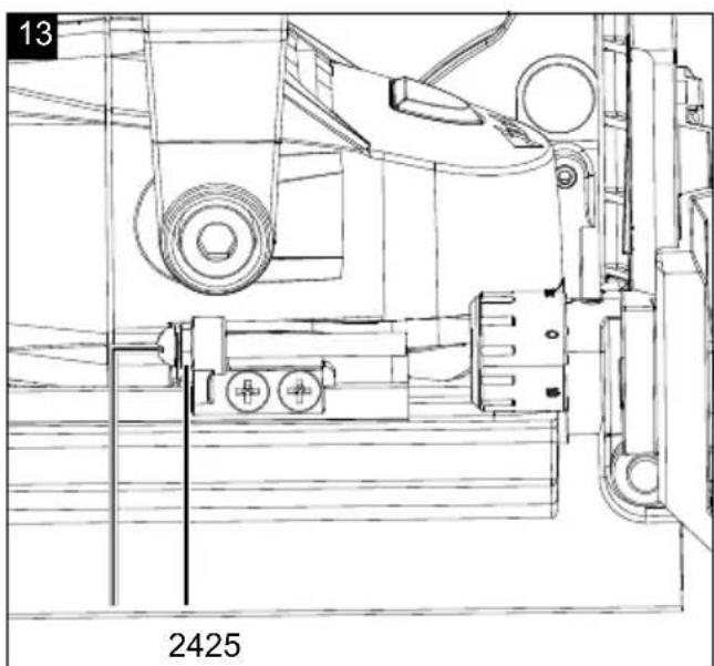
Adjusting the depth of the biscuit groove (Fig. 13)
If the depth of the biscuit groove does not match the size of the selected biscuit, you can adjust the depth accordingly.
- Loosen the counternut (24).
- To decrease the cutting depth, turn the depth adjustment screw (25) clockwise.
- To increase the cutting depth, turn the depth adjustment screw (25) anti-clockwise.
- Make a test cut.
• Tighten the counternut (24).
Service information
With this product, it is necessary to note that the following parts are subject to natural or usage-related wear, or that the following parts are required as consumables.
Wearing parts*: Cutter, carbon brushes
* may not be included in the scope of supply!
Connections and repairs
Connections and repair work on the electrical equipment may only be carried out by electricians.
Please provide the following information in the event of any queries:
• Type of current for the motor
• Data of machine type plate
• Data of motor type plate
Spare parts and accessories can be obtained from our service centre. To do this, scan the QR code on the cover page.
17. Disposal and recycling
Information on packaging


The packaging materials are recyclable. Please dispose of packaging in an environmentally friendly manner.
Information on the German Electrical and Electronic Equipment Act (ElectroG)

Electrical and electronic appliances do not belong in household waste, but should be collected and disposed of separately.
• Used batteries or rechargeable batteries
that are not installed permanently in the old appli- ance must be removed non-destructively before dis- posal. Their disposal is regulated by the battery law.
- Owners or users of electrical and electronic appliances are obliged by law to return them after use.
- The end user bears personal responsibility for deleting his personal data from the old appliance to be disposed of.
- The symbol of the crossed-through rubbish bin means that electrical and electronic appliances may not be disposed of in the household rubbish.
-
Electrical and electronic appliances can be handed in at the following places at no charge:
-
Public disposal or collection points (e.g. municipal works yards).
- Points of sale of electrical appliances (stationary and online) provided traders are obliged to take them back or offer this voluntarily.
- Up to three waste electrical devices per type of device, with an edge length of no more than 25 centimetres, can be returned free of charge to the manufacturer without prior purchase of a new device from the manufacturer or taken to another authorised collection point in your vicinity.
- Further supplementary take-back conditions of the manufacturers and distributors can be obtained from the respective customer service.
- If the manufacturer delivers a new electrical appliance to a private household, the manufacturer can arrange for the free collection of the old electrical appliance upon request from the end user. Please contact the manufacturer's customer service for this.
• These statements only apply to appliances that are installed and sold in the countries of the European Union and are subject to European Directive 2012/19/EU. Different provisions may apply to the disposal of electrical and electronic appliances in countries outside the European Union.
18. Troubleshooting
The following table shows fault symptoms and describes remedial measures in the event of your machine failing to work properly. If you cannot localise and rectify the problem with this, please contact your service workshop.
| Fault Possible cause Remedy | ||
| Product does not work. | Power supply interrupted. | Check the socket by connecting another electrical appliance to it. |
| Connection cable or mains plug defective. | Have the product repaired by a qualified specialist. | |
| Other technical defect. Have the product repaired by a qualified specialist. | ||
| Product does not work at full power. | Extension lead too long and/or conductor cross-section too small. | Use an extension lead with a permissible length and/or a sufficient conductor cross-section. |
| Voltage of the power supply (e.g. generator) too low. | Connect the product to a suitable power supply. | |
| Weak performance. Cutting disc worn out. Replace the cutting disc. | ||
| Excessive dust formation. | Dust bag full. Empty the dust bag. | |
| External dust extraction unit not connected or switched off. | Connect or switch on an external dust extractor. | |
Günzburger Straße 69
D-89335 Ichenhausen
Cher client,
natural_image
Diagram of three identical mechanical components with no visible text or symbols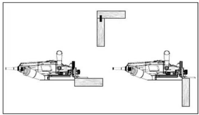
natural_image
Technical line drawing of three mechanical components with no visible text or symbolsnatural_image
Technical line drawing of a mechanical device with a separate inset showing a wooden bracket detail (no text or symbols)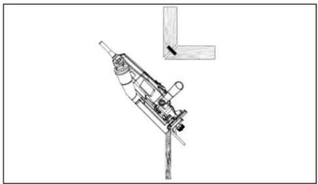
natural_image
Technical line drawing of a mechanical device with a bracket and mounting bracket (no text or symbols)natural_image
Technical line drawing of a mechanical device with wooden base and cylindrical components (no text or symbols)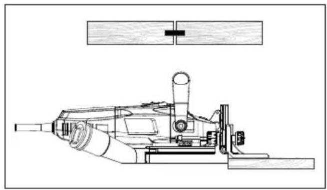
natural_image
Technical line drawing of a mechanical device with no visible text or symbolsnatural_image
Technical line drawings of mechanical components, including a drill bit and a cylindrical device with a pointed tip (no text or symbols)natural_image
Technical line drawing of a mechanical assembly with two views of a tool, no text or symbols presentEU Declaration of Conformity
| x 2006/42/EG | |
| Annex IV Notified Body: Notified Body No.: Certificate No.: | |
| 2016/1628/EU | |
| Emission. No: |
Standard references:
EN 60745-1:2009+A11; EN 60745-2-19:2009+A1;
EN IEC 55014-1:2021; EN IEC 55014-2:2021; EN IEC 61000-3-2:2019+A1; EN 61000-3-3:2013+A1+A2
This declaration of conformity is issued under the sole responsibility of the manufacturer.
The object of the declaration described above fulfils the regulations of the directive 2011/65/EU of the European Parliament and Council from 8th June 2011, on the restriction of the use of certain hazardous substances in electrical and electronic equipment.
Subject to change without notice
Documents registrar: Dawid Hudzik
Günzburger Str. 69, D-89335 Ichenhausen
Garantie DE
Apparent defects must be notified within 8 days from the receipt of the goods. Otherwise, the buyer's rights of claim due to such defects are invalidated. We guarantee for our machines in case of proper treatment for the time of the statutory warranty period from delivery in such a way that we replace any machine part free of charge which provably becomes unusable due to faulty material or defects of fabrication within such period of time. With respect to parts not manufactured by us we only warrant insofar as we are entitled to warranty claims against the upstream suppliers. The costs for the installation of the new parts shall be borne by the buyer. The cancellation of sale or the reduction of purchase price as well as any other claims for damages shall be excluded.