Plana 6.1c - Plane SCHEPPACH - Free user manual and instructions
Find the device manual for free Plana 6.1c SCHEPPACH in PDF.

| Product type | Jointer / Planer |
| Brand | Scheppach |
| Model | Plana 6.1c |
| Dimensions (L x W x H) | 1680 x 810 x 960 mm |
| Table height | 850 mm |
| Weight | 334 kg |
| Power supply | 230 V / 400 V three-phase, 50 Hz |
| Power consumption | 3.2 kW (230 V) / 3.6 kW (400 V) |
| Output power | 2.4 kW (230 V) / 2.9 kW (400 V) |
| Rated current | 13.8 A (230 V) / 5.25 A (400 V) |
| Maximum spindle speed | 4400 rpm |
| Number of blades | 4 |
| Blade type | 20 x 410 x 3 mm |
| Planer shaft diameter | 95 mm (bare shaft), 93 mm (equipped) |
| Jointer table dimensions (L x W) | 820 x 420 mm |
| Planer table dimensions (L x W) | 750 x 408 mm |
| Max. pass height | 230 mm |
| Jointer depth of cut | 0 - 3 mm |
| Feed speed | 6.5 m/min |
| Sound power level (LWA) | 106.2 dB(A) with uncertainty K=3 dB(A) |
| Dust extraction port diameter | 100 mm |
| Main functions | Joining and planing of solid wood |
| Maintenance and cleaning | Clean tables regularly of resin; oil bearings and mechanisms every 20 h; replace worn blades |
| Safety | Bridge guard, anti-kickback device, motor brake (< 10 s), emergency stop |
| Spare parts and repairability | Wear parts: belt, brushes, planer blades; repairs by qualified electrician |
Frequently Asked Questions - Plana 6.1c SCHEPPACH
User questions about Plana 6.1c SCHEPPACH
0 question about this device. Answer the ones you know or ask your own.
Ask a new question about this device
Download the instructions for your Plane in PDF format for free! Find your manual Plana 6.1c - SCHEPPACH and take your electronic device back in hand. On this page are published all the documents necessary for the use of your device. Plana 6.1c by SCHEPPACH.
USER MANUAL Plana 6.1c SCHEPPACH
natural_image
Industrial machine with metal frame and control panel (no visible text or symbols)| D | Abricht- und DickenhobelOriginal-Anleitung | 06 - 14 |
| GB | Jointer and thicknessing planerTranslation from the original instruction manual | 15 - 23 |
| FR | Dégau- RabotTraduction des instructions d'origine | 24 - 32 |
| FIN | Saumaus- ja tasohöyläkoneAlkuperäisten ohjeiden käännös | 33 - 40 |
| HU | Egyengető és vastagoló gyaluAz eredeti használati utasítás fordítása | 41 - 49 |
| CZ | Srovnávačka a tloušťkovačkaPřeklad originálního návodu k provozu | 50 - 57 |
| SK | Zrovnávačka a hrúbkovačkaPreklad originálneho návodu na prevádzku | 58 - 66 |
| NL | Vlak-vandiktebankVertaling van originele handleiding | 67 - 75 |
natural_image
Close-up of a mechanical component with a bolt and nut, showing a base and adjustment arrow (no text or symbols)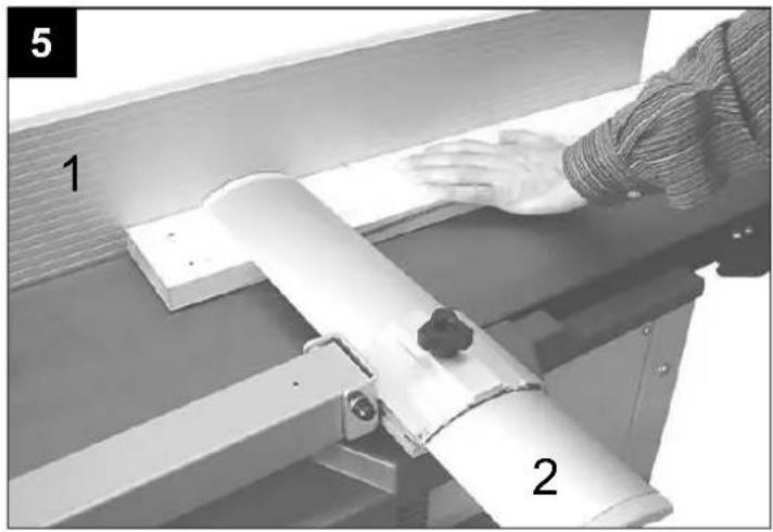
natural_image
Person operating a machine with labeled parts (1 and 2), no visible text or symbols on the device itself.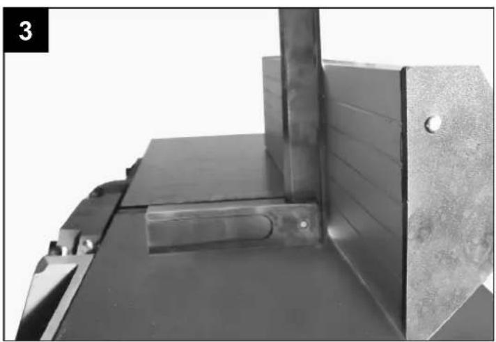
natural_image
Close-up of a metal mechanical component with a vertical rod inserted into a rectangular block (no visible text or symbols)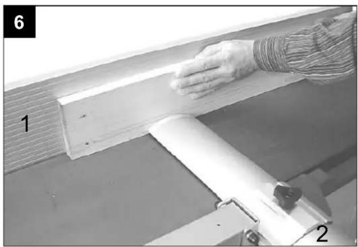
natural_image
Person using a roller on a wooden beam, no visible text or symbols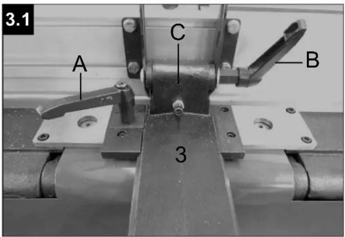
natural_image
Mechanical arm assembly with a curved blade and metal frame, mounted on a workbench (no visible text or symbols)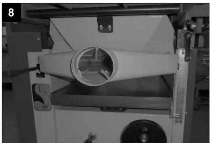
natural_image
Industrial machine with a white cylindrical component inserted into a chamber, no visible text or symbolsD
natural_image
Mechanical assembly diagram showing a motor and gear mechanism (no text or symbols)
natural_image
Close-up of a screwdriver with a head and side view showing internal components (no text or symbols visible)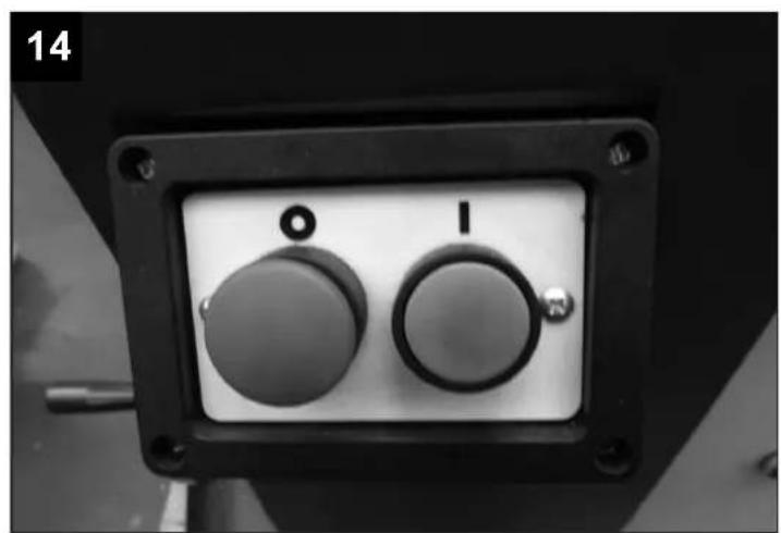
natural_image
Close-up of a black industrial control panel with two circular buttons labeled 'I' and 'O', no visible text or symbols beyond the number '14' in corner.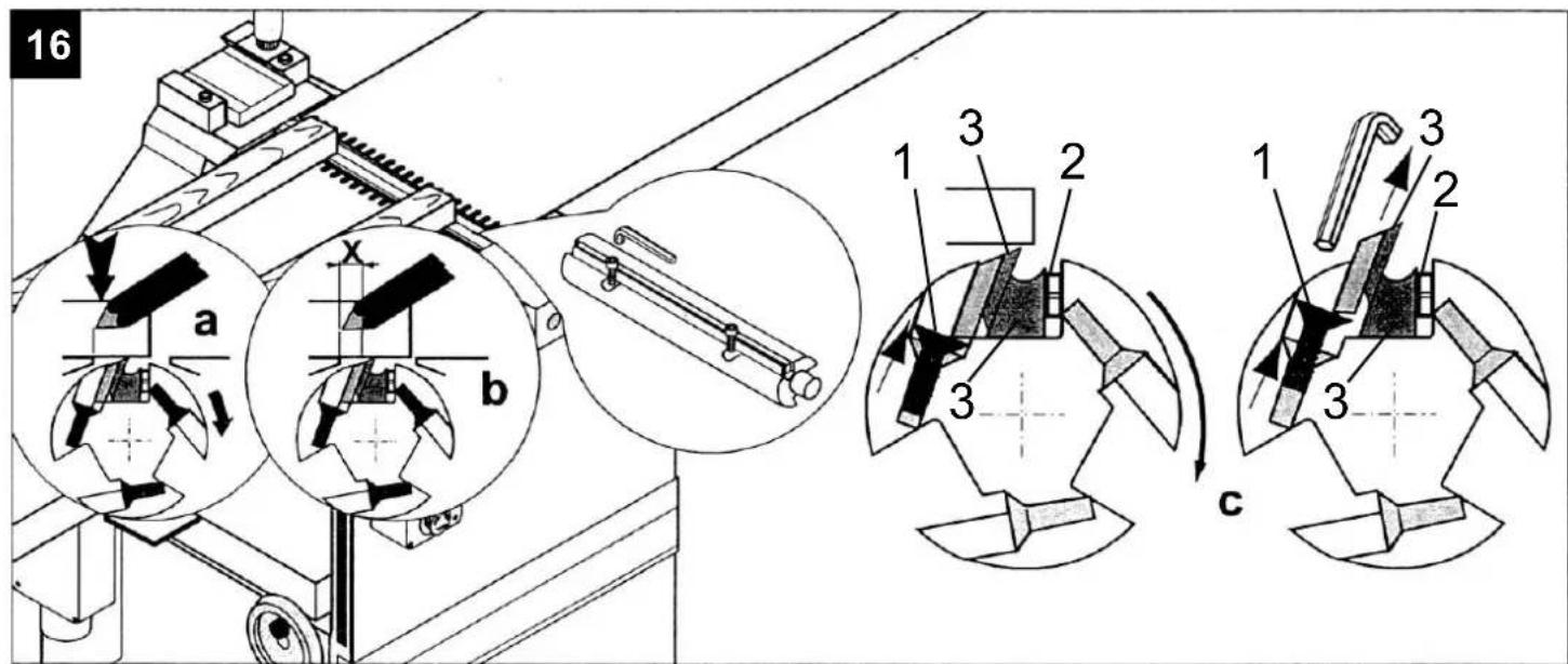
Günzburger Straße 69
| Table of contents Page: | |
| Delivery contents 16 | |
| Technical data 16 | |
| Explanation of symbols 17 | |
| General notices 17 | |
| General safety notice 17 | |
| Intended use 19 | |
| Residual risks 19 | |
| Set-up 19 | |
| Equipment fig. 1 19 | |
| Assembly 19 | |
| Commissioning 20 | |
| Operating instructions 20 | |
| Electric connection 21 | |
| Maintenance | 21 |
| Disposal and recycling | 22 |
| Trouble-shooting | 23 |
| Spare part drawings Plana 3.1c | 76 |
| Spare part drawings Plana 4.1c + 6.1c | 79 |
| Electrical scheme Plana 3.1c / 230V | 82 |
| Electrical scheme Plana 3.1c / 400V | 82 |
| Electrical scheme Plana 4.1c + 6.1c / 230V | 83 |
| Electrical scheme Plana 4.1c + 6.1c / 400V | 83 |
Delivery contents
| Planer |
| Cutterblock cover |
| Jointing fence |
| 4 base plates |
| Hexagonal key SW 5Operating instructions |
Technical data
| 250 310 410 | |||
| Dimensions L x W x H mm | 1090x510x950 1605x630x960 1680x810x960 | ||
| Table height mm | 830 850 850 | ||
| Jointer table L x W mm | 525x256 780x320 820x420 | ||
| Thicknessing table L x W mm | 660x247 750x307 750x408 | ||
| max. thickness height | 180 220 230 | ||
| Weight kg | 176 292 334 | ||
| Cutterblock | ∅ 75x250 ∅ 95x310 ∅ 95x410 | ||
| Cutterblock ø mm | ∅ 73 ∅ 93 ∅ 93 | ||
| Cutting circle ø mm | ∅ 75 ∅ 93 ∅ 93 | ||
| Revolutions max. 1/min | 4000 4400 4400 | ||
| Number of planing knives | 3 4 4 | ||
| Planing knives | 20x250x3 | 20x310x3 20x410x3 | |
| Feed speed m/min | 5,5 | 6,5 | 6,5 |
| Input power kW (230/400V) | 2,3 / 2,3 | 2,5 / 2,5 | 3,2 / 3,6 |
| Output power kW (230/400V) | 1,7 / 1,9 | 2,0 / 2,1 | 2,4 / 2,9 |
| Nominal current A (230/400V) | 10,9 / 4,05 | 9,3 / 4,2 | 13,8 / 5,25 |
Subject to technical changes!

NOISE LEVELS
| Sound conduction level LWA according to EN ISO 3744 | 106.2 dB(A) |
| Uncertainty K | 3 dB(A) |
| Sound pressure level LpA according to EN ISO 11201 | 93.2 dB(A) |
| Uncertainty K | 3 dB(A) |
Note: The specified sound levels have been determined using a standardised test procedure and can be used to compare different electronic devices. Furthermore, these values can be used to assess in advance the strain on the user caused by the sound.
Warning! Depending on how you use the power tool, the actual values can vary from those stated. Take measures to protect yourself from noise. Consider the entire work process, i.e. even times during which the power tool works
without load or is switched off. Suitable measures include, amongst others, regular maintenance and care of the power tool and the attachments, regular breaks as well as good planning of the work processes.
The figures quoted are emission levels and are not necessarily safe working levels. Whilst there is a correlation between the emission and exposure levels, this cannot be used reliably to determine whether or not further precau-
tions are required. Factors that influence the actual level of exposure of the workforce include the characteristics of the work room, the other sources of noise, etc. i.e. the number of machines and other adjacent processes. Also the permissible exposure level can vary from country to country. This information, however, will enable the user of the machine to make a better evaluation of the hazard and risk.
Explanation of symbols

Wear ear protection.

Wear a dust mask.

Wear eye protection.

Read through the manual carefully before you work on the power tool.

We have marked the points in this manual that concern your safety with this sign.
General notices
• After unpacking, check all parts for possible transportation damages. In the event of complaints, inform the supplier immediately. Any complaints made after this time will not be accepted.
- The shipment is to be checked for completeness upon receipt.
- Read through the manual carefully in order to make yourself familiar in dealing with the device before using it for the first time.
- Only use original equipment regarding accessories, as well as consumable items and spare parts. Spare parts can be obtained from your specialized dealer. When ordering, please specify our part numbers, as well as type and construction year of the device.
NOTE:
According to the applicable product liability laws, the manufacturer of the device does not assume liability for damages to the product or damages caused by the product that occurs due to:
- Improper handling,
• Non-compliance of the operating instructions,
• Repairs by third parties, not by authorized service technicians, - Installation and replacement of non-original spare parts,
• Application other than specified, - A breakdown of the electrical system that occurs due to the non-compliance of the electric regulations and VDE regulations 0100, DIN 57113 / VDE0113.
We recommend:
Read through the complete text in the operating instructions before installing and commissioning the device. The operating instructions are intended to help the user to become familiar with the machine and take advantage of its application possibilities in accordance with the recommendations. The operating instructions contain important information on how to operate the machine safely, professionally and
economically, how to avoid danger, costly repairs, reduce downtimes and how to increase reliability and service life of the machine. In addition to the safety regulations in the operating instructions, you have to meet the applicable regulations that apply for the operation of the machine in your country. Keep the operating instructions package with the machine at all times and store it in a plastic cover to protect it from dirt and moisture. Read the instruction manual each time before operating the machine and carefully follow its information. The machine can only be operated by persons who were instructed concerning the operation of the machine and who are informed about the associated dangers. The minimum age requirement must be complied with.
We have marked the points in this manual that concern your safety with this sign ⚠
General safety notices
WARNING! When using electric tools, basic safety precautions should always be followed to reduce the risk of fire, electric shock and personal injury, including the following. Read all these instructions before attempting to operate this product and safe these instructions.
1. Keep work area clean
- Cluttered areas and benches invite injuries.
- Make sure that the power cord does not impede work and cause people to trip
2. Consider work area environment
- Don't expose power tools to rain. Don't use power tools in damp or wet locations. Keep work area well lit. Don't use power tools in presence of flammable liquids or gases.
3. Guard against electric shock
- Prevent body contact with grounded surfaces (e.g. pipes, radiators, ranges refrigerators).
4. Keep children away
- Do not let visitors contact tool or extension cord. All visitors should be kept away from work area.
5. Store idle tools
- When not is use, tools should be stored in dry, high, or locked-up place, out of the reach of children.
6. Don't force tool
- It will do the job better and safer at the rate for which it was intended.
7. Use right tool
- Don't force small tools or attachments to do the job of heavy duty tool. Don't use tools for purposes not intended: for example, don't use circular saw for cutting tree limbs or logs.
8. Dress properly
- Do not wear loose clothing or jewelry. They can be caught in moving parts. Wear protective nair covering to contain long hair.
- Do not wear gloves while operating this machine
9. Use safety glasses
- Also use face or dust mask if cutting operation is dusty.
10. Don't abuse cord
- Never carry tool by cord or yank it to disconnect it from receptacle. Keep cord from heat, oil and sharp edges.
11. Secure work
- Use clamps or a vise to hold work. It's safer than using your hand and it frees both hands to operate tool.
12. Don't overreach
- Keep proper footing and balance at all times.
13. Maintain tools with care
- Keep tools sharp and clean for better and safer performance. Follow instructions for lubricating and changing accessories. Inspect tool cords periodically and, if damaged, have repaired by authorized service facility. Inspect extension cords periodically and replace if damaged. Keep handles dry, clean and free from oil and grease.
14. Disconnect tools
- When not in use, before servicing, and when changing accessories such as blades, bits and cutters.
15. Remove adjusting keys and wrenches
- Form the habit of checking to see that keys and adjusting wrenches are removed from tool before turning it on.
16. Avoid unintentional starting
- Don't carry plugged-in tool with finger on switch. Be sure switch is off when plugging in.
- Never leave a running machine unattended. Before you leave the workplace switch off the machine.
17. Outdoor use extension cords
- When tool is used outdoors, use only extension cords intended for use outdoors and so marked.
18. Stay alert
- Watch what you are doing. Use common sense. Do not operate tool when you are tired.
- Do not operate the machine under the influence of drugs, alcohol or any medication. Be aware that medication can change your behaviour.
19. Check damaged parts
- Before further use of the tool, a guard or other part that is damaged should be carefully checked to determine that it will operate properly and perform its intended function. Check for alignment of moving parts, binding of moving parts, breakage of parts, mounting, and any other conditions that may affect its operation. A guard or other part that is damaged should be properly repaired or replaced by an authorized service center unless otherwise indicated elsewhere in this instructions manual. Have defective switches replaced by an authorized service center. Do not use tool if switch does not turn it on and off.
20. Warning
- The use of any other accessory or attachment other than recommended it this operating instruction or the Einhell catalog may present a risk of personal injury.
21. Have your tool repaired by an expert
- This electric appliance is in accordance with the relevant safety rules repairing of electric appliances may be carried out only by experts otherwise it may cause considerable danger for the user.
22. Connect the dust extraction devic
- Wherever there are facilities for fitting a dust extraction system, make sure it is connected and used.
Additional safety instructions
Do not use blunt knives. Risk of kick-back. The cutter block must be fully covered.
Use a push stick to plane any short workpieces. Take additional safety precautions if you are planing any narrow workpieces. It may be necessary to use lateral pressure equipment and springloaded covers to ensure that you can work insafety.
The machine is not suitable for cutting rebates. The anti-kick safeguard and the infeed roller must be inspected at regular intervals. Machines fitted with a sawdust extractor and extractor hoods must be connected to the devices concerned. The type of material used can have a negative influence on the dust generated.
The machine is designed exclusively for the cutting of wood and similar materials.
The knife must be replaced immediately once it becomes worn down by 5%.
If a push stick is not used there may be a risk of serious danger. The push stick should always be kept at the point provided on the left-hand side of the machine when not used.
There is a greater risk of danger when small workpieces are fed in by hand. Always observe the manufacturer's instructions on the use of the push stick.
If the safety covers, infeed table or mesh are incorrectly aligned they could lead to uncontrollable situations. Damaged or soiled workpieces may cause a risk of danger. Never use metal parts in the machine or any materials which can fracture or shatter.
Risk of injury! To cut long workpieces, always place them on a mobile table or similar type of supporting equipment. Otherwise there is a risk that you may lose control over the workpiece. The machine is only suitable for planing and thickening.
Wear suitable protective clothing when working with the machine.
- ear protection to prevent damage to your ears,
- a breathing mask to avoid the risk of inhaling hazardous particles of dust,
- safety gloves to avoid injuries from sharp edges or knives,
- safety goggles to avoid eye injuries from flying parts.
It is imperative that the following situations are avoided at all times: Premature interruption of the cutting operation (planing cuts which do not complete the entire length of the workpiece; planing of uneven pieces of wood which do not lie flat on the infeed table). The machine is designed for private use only. It is prohibited to use the machine for professional or commercial use. Residual risk: Bear in mind that there is always the possibility of residual risks associated with the use of the machine even if you comply with all the safety instructions. By complying with these instructions and taking suitable care when using the machine you will reduce the risk of injury or of damage to the machine. Particular risks:
- Injuries to fingers or hands from parts of the machine or from workpieces, e.g. when changing the planing knife
- Risk of electric shock if you use power connections which do not comply with standards
- Contact with conductive parts on opened electrical components
- Hearing impairments if you work for lengthy periods without ear protection
- Emission of hazardous sawdust if a dust extractor is not used.
Even if all safety precautions are complied with it is still possible for some residual risks to remain.
Important! If the primary mains connection is in a poor condition there is a risk of short-circuits when the machine is switched on. This may also affect other functions (e.g. the lighting up of indicator lamps). Should there be any faults in the primary mains connection (max. current impedance < 0.105 Ω), please contact your local electricity supplier to advice and information.
If the blade is fastened and positioned incorrectly this may result in the blade being flung out, which may be a cause of danger. Therefore, before operation, make sure that the blade is correctly fitted and adjusted in accordance with the operating instructions. Every part of the blade shaft not used for planning must be covered.
Check the machine and carry out required maintenance work on it each time before you start it up. In particular, inspect all the anti-kick claws and the infeed drive shaft.
Make sure that the dust extraction system and collector are connected and are used correctly. Make sure that the dust extraction system is suitable. Fine sawdust may not only be harmful to health, in certain concentrations it can also be potentially explosive. Always switch off the machine and pull out the mains plug before making any adjustments or changing settings. Sawdust may cause risks to health.
Please keep these safety instructions in a safe place.
Warning! This electric tool generates an electromagnetic field during operation. This field can impair active or passive medical implants under certain conditions. In order to prevent the risk of serious or deadly injuries, we recommend that persons with medical implants
consult with their physician and the manufacturer of the medical implant prior to operating the electric tool.
Intended use ⚠️
- The planer has been constructed exclusively for processing wood using the tools and accessories on offer. No metal workpieces my be machined.
- The machine complies with the relevant EC machine guidelines.
- The machine has been designed for single-shift operation, duty-cycle S1.
- All safety and hazard notices on the machine must be observed.
- All safety and hazard notices on the machine must be kept in a completely legible condition.
- When the machine is being used in a closed room, an extraction unit has to be connected.
- Use an extraction unit to remove shavings or saw dust. The flow rate at the extraction port
must be 20 m/s. Negative pressure 1200 Pa.
- For work in a commercial area, a deduster has to be used. Do not switch off or remove extraction units or dedusters when the machine is running.
- Use the machine in a technically flawless condition only, as well as for its intended purpose, in a safe manner and being aware of dangers, in compliance with the operating instructions! Failures which can affect safety in particular must be removed straight away!
- The manufacturer's stipulations concerning safety, work and maintenance as well as the measurements specified in Technical data, must be complied with.
-
The relevant accident prevention stipulations and other widely recognised safety rules must be observed.
-
The machine may be used, maintained or repaired only by expert personnel who are familiar with it and its dangers. Unauthorised changes to the machine invalidate the manufacturer's liability for damages resulting from this.
- The machine may be used only with the manufacturer's original accessories and original tools.
- Every use beyond that is deemed as not intended. The manufacturer is not liable for damage resulting from this, the risk lies exclusively with the user.
Residual risks ⚠️
- The machine has been built according to the latest technology and recognised safety rules. However, individual residual risks can occur when working: Risk of injury to fingers and hands from the rotating cutterblock during incorrect handling of the work piece. Never reach with your hands under the cutter block guard when guiding the work piece! Do not pull the work piece back over the unguarded cutter block.
- Injuries when the work piece is ejected during incorrect mounting or handling, such as working without a fence.
• Health risk from wood dust and shavings.
- Make sure you wear personal protective equipment such as eye protection and a dust mask. Use an extraction unit!
- Health risk from noise during work, the permitted noise level is exceeded. Make sure you wear personal protective equipment such as hearing protection.
- Electrical hazards when unsuitable electric connections are used
- Process chosen wood only, without imperfections such as: Knots, transverse cracks, surface cracks, foreign objects (nails,
screws). Flawed wood creates a risk during work.
• Furthermore, despite all measures taken, residual risks can occur that are not obvious.
- Residual risks can be minimised by complying with the safety notices and the intended use as well as the operating instructions overall
- Drawing-in/trapping hazard by power feed mechanism.
- Squeezing hazard by work piece power-outfeed.
Set-up
Prepare the work place where the power tool will be used. Make sufficient space so that safe and uninterrupted work is ensured. The power tool has been designed for work in closed rooms, and it has to be set up on an even, level, solid surface in a stable position.
Fixing the machine on level hard concrete floor before operation.
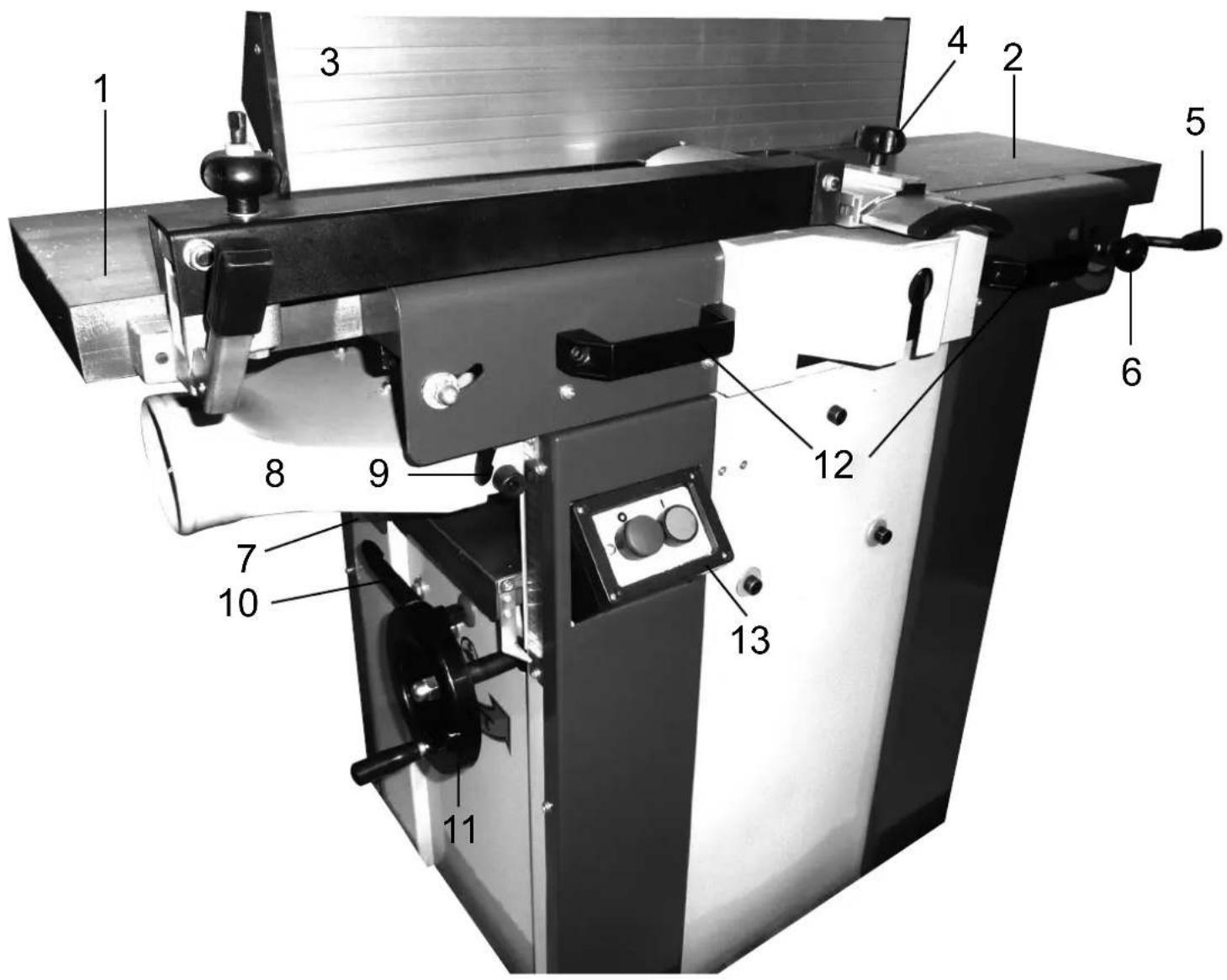
Equipment fig. 1
- Jointer table fixed
- Jointer table adjustable
- Jointing fence
- Cutterblock cover
-
Table adjustment lever
-
Locking handle for thicknessing table
- Infeed locking lever
- Extraction hood
- Table locking system
-
Thicknessing table clamping
-
Height adjustment caster
- Handles to adjust the height of the jointer tables
- On-/off-switch
Assembly
Due to packaging reasons, your planer is not completely assembled.
The planer must not be lifted by the jointer tables!
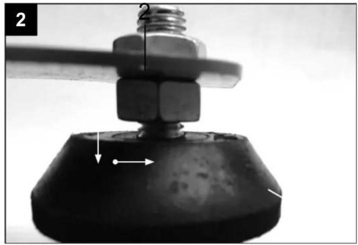
Attaching and adjusting of base plates fig. 2
Attach 4 base plates to the bottom of the frame, Slightly tighten hexagon nuts by hand. In order to balance out an uneven surface, loosen the lock nuts and turn the base plates in or out accordingly. Tighten the lock nut again.
Warning! Make sure you align the machine using a spirit level.
Attaching the jointing fence fig. 3 Insert the jointing fence (3) in the track and tighten it with the clamping lever (A).
Adjusting the jointing fence fig. 3.0, 3.1
- Loosen the clamping lever (B).
- Using a try-square, determine the 90^ angle of the jointer table to the stop surface,
-
tighten the clamping lever (B).
-
Loosen the lock nut, adjust the fence with the cylinder screw (C).
- Tighten the lock nut again.
Warning!
The jointing fence always has to be secured safely.
Clamping is carried out with the clamping le-vers (A + B) fig 3.1.
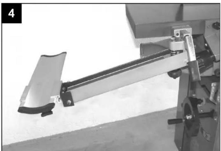
Attaching the cutterblock cover fig. 4
Attach and tighten the cutterblock cover on the side of the jointer table with 2 Allen screws.
The cutterblock cover can be turned away without tools by pulling the cam lever up, turning the cutterblock cover away, and pushing the cam lever down again.
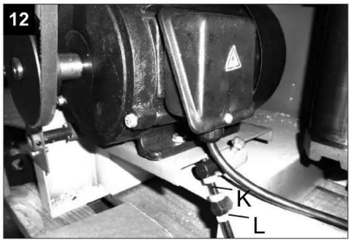
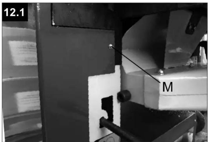
For Plana 4.1 and 6.1 fig. 12, 12.1
- Loosen 1 recessed head screw (M) each on both sides of the rear panel,
- lift the rear panel slightly and take it off.
Loosen the lock nut (K), tension the belt by turning the hexagon screw (L), tighten the lock nut again.
- Insert the rear panel and secure it again with the 2 recessed head screws.
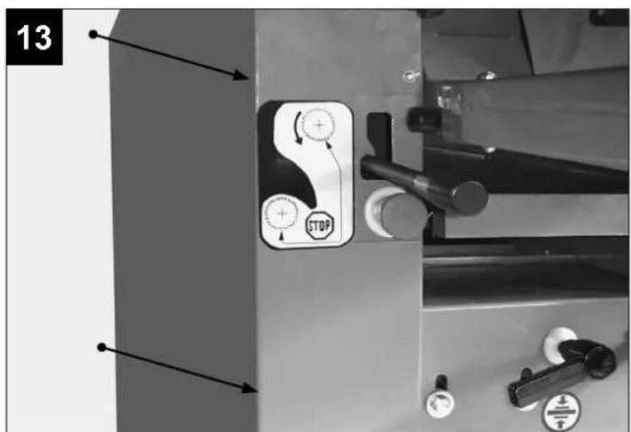
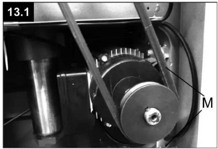
For Plana 3.1 fig. 13, 13.1
- Remove 6 recessed head screws left and right on the rear panel. Loosen 4 mounting
screws (M) on the motor.
- Use a wooden board as a lever between the motor and the casing for tensioning.
- Tighten the 4 mounting screws again.
- Check the belt tension after tightening.
- Re-attach the rear panel.
Commissioning
Before commissioning, be aware of the safety notices. All protective and auxiliary equipment must be attached.
Carry out work such as re-tooling, adjusting, measuring and cleaning only when the motor is switched off.
Disconnect the mains plug!
Motor brake:
Before operation, test the run down time, it should be less than 10s.
Practical example - dressing fig. 5 + 6
Warning! Never work with a jointer without the cutterblock cover.
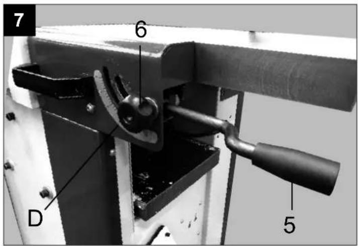
Jointer work - takeoff fig. 7
During jointer work, the takeoff can be adjusted from 0 – 3 mm via the table adjustment lever (5).
Warning! Loosen the locking handle (6) first when adjusting, adjust the takeoff on the scale (D) with the table adjustment lever and re-tighten the locking handle (6).
With longer work pieces (longer than the loading and unloading table), a dolly (special accessory) or something similar has to be used.
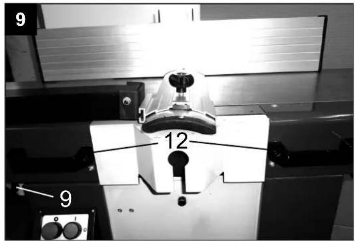
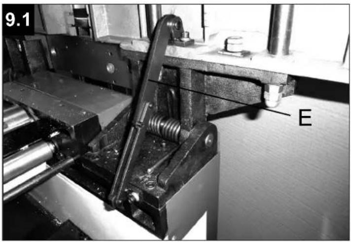
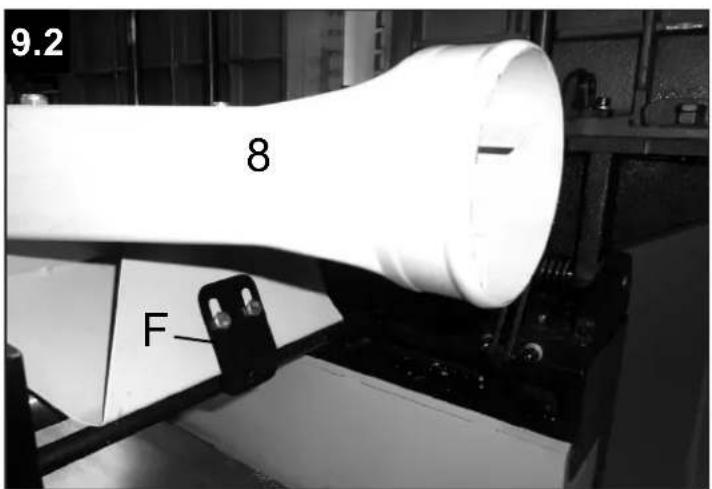
Thicknessing - machine set-up Fig. 9.0, 9.1, 9.2.
Changing from dressing to thicknessing Unlock the jointer tables on both sides by un-clamping and removing both cam levers fig. 9 (9).
Push both tables up by the handles fig. 9 (12) until the catch fig. 9.1 (E) clicks into place.
Rotate the ejection hood for shavings (8) upwards until it clicks into place with the spring U-bolt fig. 9.2 (F).
Extraction can then take place in conjunction with an extraction unit.
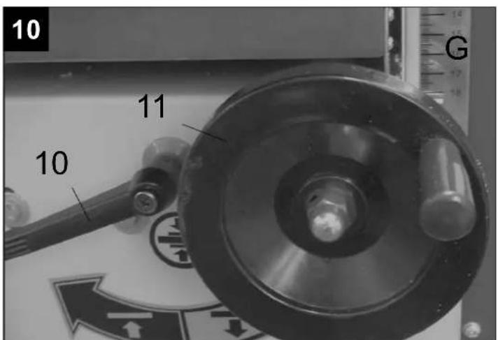
Thicknessing - table adjustment fig. 10
The thicknessing table can be height-adjusted with the handwheel (11) and it is secured against displacement with the thicknessing table clamp (10)
The integrated position display (G) shows the aperture height.
One turn corresponds to 2 mm.
Always keep the thicknessing table as well as the jointing tables free from resin.
Adjusting the scale during planing fig. 10
If there are irregularities, the scale (G) can be adjusted. For this, loosen both mounting screws, align the scale exactly and tighten both screws again.
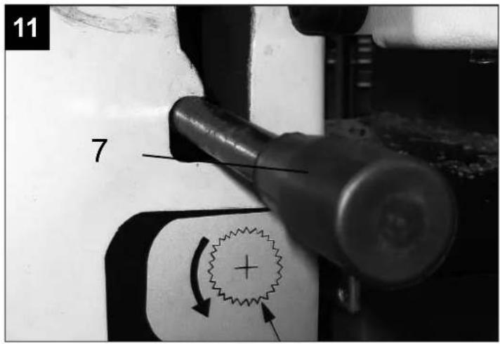
Automatic infeed in thicknessing operation fig. 11
The automatic infeed is switched on and off via the infeed locking lever (7).
Position top = on
Position bottom = stop
When the infeed is switched on, the wood is automatically fed in and a precise and consistent surface is the result.
During dressing, it is recommended to turn the infeed off.
The infeed can also be turned off for safety reasons.
V-belt tension motor
Warning! Always disconnect the mains plug during all re-tooling and adjusting work.
Tension the v-belt again after 3 hours of initial operation. The belt tension also has to be
checked regularly after 40 operating hours and, if needed, tensioned again.
Jointer work - cutterblock cover fig. 5
When dressing up to a 100 mm work piece width, the cutterblock cover has to cover the work piece and the cutterblock from the top. If the work piece is wider than 100 mm, set the guard rail of the cutterblock cover to the width of the work piece. Make sure you put the flat of the hand with all five digits together and extended on the work piece.
- Jointing fence
- Cutterblock cover
Joining, fig. 6
For this procedure, use the jointing fence. Place the cutterblock cover on the jointer table and set the guard rail to the width of the work piece.
Press the work piece against the planing fence and guide it over the cutterblock with both hands. As soon as the board reaches far enough into the unloading table, put your left hand on it and push it over the cutter without stopping.
Jointer work – ejection of shavings fig. 8
During jointer work, the jointer table has to be locked.
The extraction hose must be attached to the extraction hood.
Extraction can then take place in conjunction with an extraction unit (special accessory).
Diameter of the extraction port - 100 mm
Operating instructions
■ SET-UP AND ADJUSTMENT OF THE MACHINE
- Carry out work such as re-tooling, adjusting, measuring and cleaning only when the motor is switched off. Disconnect the mains plug and wait for the rotating tools to stop moving.
■ THICKNESSING AND JOINTER WORK
• Maximum revolutions of the cutterblock 4000 1/min
- The cutterblock has been manufactured in accordance with DIN EN 847-1.
- Start the process only when full revolutions have been reached.
- Keep the operating area of the machine free
- All protective and safety equipment must be re-attached immediately after completing repairs and maintenance.
- Replace faulty planing knives (flaws or similar) straight away. See Replacement of knives!
from shavings and wood debris.
- Use an extraction unit to extract shavings and wood dust. The flow rate at the extraction port must be 20 m/s.
-
Work only with sharpened planing knives. Blunt planing knives increase the risk of recoil.
-
Check the effectiveness of the return prevention system before every process step. The hook-tips must be sharp.
-
All protective and safety notices must be re-attached immediately after completing repairs and maintenance.
-
Thickening: Feed with thicker work piece end at the front, hollow side downward. Machine max. 2 work piece at one time, feed on both outer sides.
-
When working on longer work pieces (longer than the loading table), use dollies (special accessory).
-
Dressing: When dressing up to a 100 mm width work piece, the cutterblock cover has to cover the work piece and the cutterblock from the top. If the work piece is wider than 100 mm, set the guard rail of the cutterblock cover to the width of the work piece. Make sure you put the flat of the hand with all five digits together and extended on the work piece.
- Joining: The work piece is positioned against the jointing fence. Set the guard rail of the cutterblock cover to the width of the work piece and place it on the table.
- Dressing and joining of small cross sections (slats): During dressing, the work piece is
pushed forwards with hands sitting flat on it, as is the case with work pieces up to a width of 100 mm. During joining, the work piece is pushed against the stop with both hands, fists closed, and pushed forwards. The guard is positioned at the fence and lies on the work piece.
- Dressing and joining of short work pieces (min. length 150mm): During dressing, the work piece is pressed on the loading table with a flat hand and pushed forwards with the push block guided by the right hand. The left hand glides over the guard. As soon as the work piece lies on the unloading table, the pressure from the left hand is changed
to the unloading table. During joining, the work piece is pressed against the fence and the table with the left hand, fist closed, and pushed forwards with the push block.
- Chamfering or bevelling: The work piece is positioned against the jointing fence. Set the guard rail of the cutterblock cover to the width of the work piece and place it on the table. The work piece is pressed against the fence and the unloading table with the left hand, fist closed, and pushed forwards with the closed right hand.
- Warning! Never work with a jointer without the cutterblock cover.
Electric connection ⚠️
- Check the mains connection cables. Do not use faulty cables. See Electric connection.
- Observe the rotational direction of the motor and the tools, see Electric connection planer.
• Installations, repairs and maintenance on the electric installation may be carried out only by experts. - Turn the machine off when resolving issues. Disconnect the mains plug.
- Turn the motor off when you leave the work place. Disconnect the mains plug.
- Disconnect the machine from every external energy supply even for slight changes of position! Connect the machine to the mains again before using it!
Connect the machine to the mains with a CEE-plug, the supply line has to be protected with 16 A.
On the operating switch, press the green push button, the cutterblock starts up (fig. 14).
To turn it off, press the red push button, the cutterblock stops within 10 sec.
Change of rotational direction
When connecting the machine to the mains or changing its position, the rotational direction has to be checked. The polarity has to be swapped, if applicable, using a screw driver (machine socket fig. 15).
The installed electric motor is connected and operational. The connection complies with relevant VDE and DIN stipulations. The mains connection at the customer's as well as the extension lead used have to comply with these stipulations or the local EVU-stipulations.
Duration of use / duty cycle
The electric motor is for operating type S1 for continuous operation.
When there is an overload, the motor turns itself off because a winding thermostat is integrated in the motor development. After a cooldown period (timing varies), the motor can be turned on again.
Hazardous electric connections Insulation damage often occurs on electric connections.
Possible causes:
- Pressure marks when connections are guided through windows and doors
- Kinks due to inappropriate attachment or guidance of the connection
• Cuts when the connection is run over
• Insulation damage when being pulled out of the wall socket - Tears from ageing insulation. Such hazardous electric connections must not be used and are dangerous to life due to the insulation damage.
Regularly check electric connections for damage. Make sure the connection is not connected to the mains when checking. Electric connections must comply with relevant VDE and DIN stipulations and the local EVE stipulations. Only use connections marked H 07 RN. Printing the type designation on the connection is the law. Extension leads up to 25 m in length must have a cross section of 1.5 mm ^2 , at more than 25 m length, it has to be at least 2.5 mm ^2 .
The mains connection is protected against short circuit with a 16 A slow fuse.
Three-phase motor
The power voltage has to be 380÷420 V 50 Hz. Mains connection and extension leads have to be 5 core =3 P + N + SL.
Extension leads must have a minimum cross section of 1.5 mm^2 .
The mains connection is protected against short circuit at a maximum of 16 A.
When connecting the machine to the mains or changing its position, the rotational direction has to be checked. The polarity has to be swapped, if applicable, using a screw driver (machine socket fig. 15).
One-phase motor
The power voltage has to be 230 V 50 Hz.
Connections and repairs to the electrical equipment may be carried out only by a trained electrician.
If there are any questions, please provide the following data:
- Motor manufacturer; motor type
- Motor's type of power
- Data from the machine's type plate
• Data from the electronic control
When sending back the motor, always send the entire motor unit with electronic control.
Maintenance

WARNING
Before working on the power tool itself (e.g. transport, set-up, re-tooling, cleaning and maintenance), disconnect the mains plug from the socket!
■ CLEANING
Carry out maintenance, service and repairs as well as malfunctions only when the motor is turned off. Turn the machine off via the off-switch, then disconnect the mains plug!
All protective and safety equipment must be re-attached immediately after completing repairs and maintenance.
Always keep the jointer tables and the thick-nessing table free from resin. The bearings of the cutterblock are permanently lubricated.
Warmth occurring when the machine is in a new condition is due to construction and will disappear with time.
Clean the feed rollers regularly.
After the first 5 operating hours, oil the plain bearings of the feed rollers, the adjustment spindle of the thicknessing table, their bearings. Repeat every 20 operating hours with further use.
Planing knives
The HSS planing knives inserted in the factory are operational and set up correctly.
Only well-sharpened and correctly set-up planing knives guarantee safe work.
We recommend: Always keep a second set of new planing knives ready for replacement.
Replacement planing knives are available from your stockist.
Inserting planing knives fig. 16
- Setting screw
- Pressure screw
- Planing knives
- V-ledge
When inserting, be aware that
• there is a risk of injury to fingers and hands.
- the clamping areas in the cutter and the v-ledges are cleaned.
• the sharpened planing knives are oiled.
- only knives re-sharpened in sets are used.
- inserting the planing knives and v-ledges is carried out according to the figure.
- the planing knives, knife supports and v-ledges are flush with the cutter on both sides.
• the clamping screws are tightened (8.9 N/m).
GB Warning!
The details concerning knife attachment, knife protrusion, knife width, min. clamping length and ideal tightening torque of the knife mounting screws have to be complied with exactly.
Setting up the planing knives fig. 16a, b, c
- The HSS planing knives are inserted in the factory and set up correctly.
If required, you can re-do the settings or refine them as described.
- Adjust one planing knife after the other.
- Set the position of the planing knife using the setting screws alternatively until the blade of the knife touches both perfectly trimmed boards (used as adjustment gauge) which are placed on the unloading table.
- Set the loading table to a dressing height of 2 mm.
- Rotate the cutterblock until the knife has reached the maximum height.
- The planing knives are positioned on the head of the setting screws in the slot of the cutterblock. Let the knives touch the boards by unscrewing the setting screws with an Allen key.
- Align the knife support and check the position of the knives again.
- Checking the knives
Put a trimmed board (adjustment gauge) on the unloading table and mark the position of the board.
By turning the cutterblock in the cutting direction by hand, the knife blade should move the board by x = 2 to 3 mm. Carry out this check for every knife on the operating side and on the other side.
Without careful settings, the trimming cannot be exact.
- Tighten the pressure screws on the v-ledge with a flat spanner (8.9 N/m).
- Adjust all planing knives in the same way and clamp them.
- Carry out a test-run after every knife replacement and tighten the pressure screws afterwards (8.9 N/m).
Before using the cutterblock, check if the instructions above were followed.
Before turning on the machine, the general safety notices must be observed.
Sharpening of planing knives
Blunt planing knives increase the risk of accidents and the performance is no longer guaranteed.
Re-sharpen the planing knives only up to a knife height of 16 mm. The cutting angle of the knife should be 40 ± 2 degrees.
For re-sharpening, take the planing knives to an authorised sharpening company or send them back to the manufacturer.
Günzburger Straße 69
0-89335 Ichenhausen / BRD
Planing knives:
Plana 3.1c
Set of HS-planing knives 250: 790 2200 601
Set of reversible knives 250: 330 4200 030
Set of knife supports 250: 330 4300 038
Plana 4.1c
Set of HS-planing knives 310: 330 4000 010
Set of HS-planing knives 310: 730 2200 603
Set of reversible knives 310: 330 4200 031
Set of knife supports 310: 790 2200 602
Plana 6.1c
Set of HS-planing knives 410: 790 2200 604
Service information
Please note that the following parts of this product are subject to normal or natural wear and that the following parts are therefore also required for use as consumables.
Wear parts:* motor drive belt, carbon brushes, planer blades
* Not necessarily included in the scope of delivery!
Disposal and recycling
The equipment is supplied in packaging to prevent it from being damaged in transit. The raw materials in this packaging can be reused or recycled. Never place batteries in your household refuse, in fire or in water. Batteries should be collected, recycled or disposed of by environment-friendly means. The equipment and its accessories are made of various types of material, such as metal and plastic. Defective components must be disposed of as special waste. Ask your dealer or your local council!
Old devices must not be disposed of with household waste!
This symbol indicates that this product must not be disposed of together with domestic waste in compliance with the Directive (2012/19/EU) pertaining to waste electrical and electronic equipment (WEEE). This product must be disposed of at a designated collection point. This can occur, for example, by handing it in at an authorised collecting point for the recycling of waste electrical and electronic equipment. Improper handling of waste equipment may have negative
consequences for the environment and human health due to potentially hazardous substances that are often contained in electrical and electronic equipment. By properly disposing of this product, you are also contributing to the effective use of natural resources. You can obtain information on collection points for waste equipment from your municipal administration, public waste disposal authority, an authorised body for the disposal of waste electrical and electronic equipment or your waste disposal company.
Trouble-shooting
| Problem Possible cause Solution | ||
| 1. Irregular and interrupted transport during thicknessing | Thicknessing table resinified or not oiled. Clean the thicknessing table regularly and spray it (lubricant). This applies particularly to damp and resinous wood. | |
| 2. Work piece ledge during jointer work | This is caused by badly adjusted planing knives. | The adjustment of the planing knives has to be carried out with great care and by using the setting rule. |
| 3. Work piece irregularity during jointer work (hollow, crowned) | Caused by jointer tables not standing exactly parallel after incorrect transport or similar. Never lift the machine by the tables. | Adjust the stiff trimming desk 1 mm above the plan-ing shaft body, as well as parallel to the bottom plate. |
| Electrical maintenance work may be carried out only by a qualified electrician! | ||
| When disposing of the machine, local legal stipulations must be complied with. | ||
Günzburger Straße 69
D-89335 Ichenhausen
Fers de rabot:
Plana 3.1c
Jeu de fers HS 250: 790 2200 601
Günzburger Straße 69
0-89335 Ichenhausen / BRD
Höylänterät:
Plana 3.1c
Sarja HS-höylänteriä 250: 790 2200 601
Günzburger Straße 69
Günzburger Straße 69
Günzburger Straße 69
Günzburger Straße 69
CE - Declaration of Conformity
Standard references:
EN 60204-1:2006+A1:2009; EN 55014-1; EN 55014-2; EN 61000-3-2; EN 861:2007+A2:2012
This declaration of conformity is issued under the sole responsibility of the manufacturer.
The object of the declaration described above fulfils the regulations of the directive 2011/65/EU of the European Parliament and Council from 8th June 2011, on the restriction of the use of certain hazardous substances in electrical and electronic equipment.
Subject to change without notice
Apparent defects must be notified within 8 days from the receipt of the goods. Otherwise, the buyer's rights of claim due to such defects are invalidated. We guarantee for our machines in case of proper treatment for the time of the statutory warranty period from delivery in such a way that we replace any machine part free of charge which provably becomes unusable due to faulty material or defects of fabrica-
tion within such period of time. With respect to parts not manufactured by us we only warrant insofar as we are entitled to warranty claims against the upstream suppliers. The costs for the installation of the new parts shall be borne by the buyer. The cancellation of sale or the reduction of purchase price as well as any other claims for damages shall be excluded.