Plana 3.0 - Plane SCHEPPACH - Free user manual and instructions
Find the device manual for free Plana 3.0 SCHEPPACH in PDF.

User questions about Plana 3.0 SCHEPPACH
0 question about this device. Answer the ones you know or ask your own.
Ask a new question about this device
Download the instructions for your Plane in PDF format for free! Find your manual Plana 3.0 - SCHEPPACH and take your electronic device back in hand. On this page are published all the documents necessary for the use of your device. Plana 3.0 by SCHEPPACH.
USER MANUAL Plana 3.0 SCHEPPACH
natural_image
Black industrial machine labeled 'scheepack Plans 3.0' with no visible text or symbols on the device itself.CE
0.002.0
scheppach
| D | -9 |
| GB | 0-15 |
| FR | 6-22 |
| I | 3-29 |
| NL | 30-36 |
| E | 7-43 |
| PT | 4-50 |
| DK | 51-56 |
| NO | 57-63 |
| FIN | 54-70 |
| SE | 1-77 |
| RU | 78-85 |
| SLO | 86-92 |
| PO | 3-99 |
| CZ | 00-106 |
| SK | 07-113 |
Fig. 2
natural_image
Close-up of a mechanical device with two rectangular components and a handle (no visible text or symbols)Fig. 5.2
natural_image
Mechanical assembly diagram showing a clamp and lever mechanism (no text or symbols visible)Fig. 6.1
natural_image
Close-up of a mechanical assembly with black components and mounting brackets (no visible text or symbols)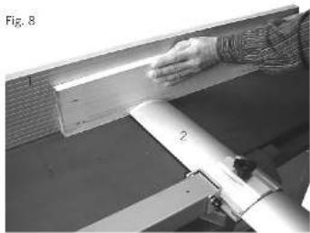
natural_image
Person using a tool on a workbench, no visible text or symbolsFig. 3
natural_image
Technical line drawing of a mechanical component with a lever and housing (no text or symbols)Fig. 5.3
natural_image
Mechanical assembly with black components and metallic frame (no visible text or symbols)Fig. 6.2
natural_image
Interior view of a laboratory apparatus with cooling fans and a directional arrow (no visible text or symbols)Fig. 9
natural_image
Close-up of a mechanical device with a cylindrical pipe being processed (no visible text or symbols)Fig. 4
natural_image
Pure mechanical assembly diagram showing a beam supported by two bolts and a base plate (no text or symbols)Fig. 5.4
natural_image
Close-up of a mechanical arm or lever assembly with a metallic clip and black base, no visible text or symbolsFig. 7
natural_image
Person operating a mechanical device with a cylindrical component (no visible text or symbols)Fig. 10.1
natural_image
Close-up of a mechanical device with a black component and metallic parts (no visible text or symbols)Fig. 5.1
natural_image
Mechanical assembly with a lever and bracket, no visible text or symbols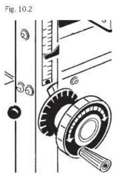
natural_image
Close-up of a mechanical device with mounting holes and a central component, labeled Fig. 11 (no text or symbols on the device itself)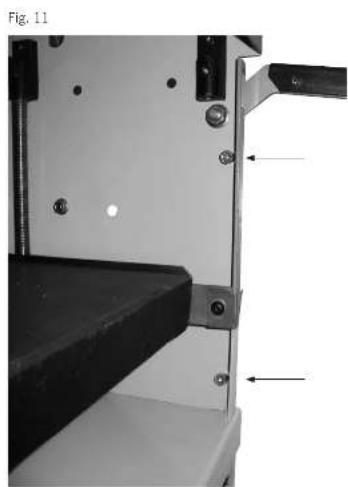
natural_image
Mechanical assembly diagram showing a clamping mechanism with two bolted components and mounting holes (no text or symbols)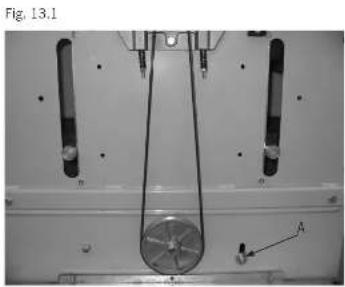
natural_image
Mechanical assembly diagram showing a rotating component with labeled points A and B, no readable text or symbols present.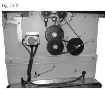
natural_image
Interior view of an electronic device with labeled components (A, C) and wiring, no readable text or symbols beyond labels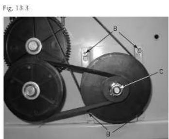
Günzburger Straße 69
D-89335 Ichenhausen
■ VEREHRTER KUNDE,
Manufacturer of Woodworking Machines GmbH
Günzburger Straße 69
D-89335 Ichenhausen
■ VALUED CUSTOMER,
We hope that you enjoy your new machine and wish you every success in working with it. Warning: The manufacturer of these devices is not liable, under the applicable Product Liability Act, for damages to this device or by this device resulting from:
- improper handling,
• noncompliance with the operating instructions,
• repairs by a third, non-authorized party - installation and replacement of non-original spare parts,
• utilization, noncompliant with the regulations, - failure of the electric equipment resulting from violation of the electric specifications and VDE (Association of Electrotechnology) regulations 0100, DIN 57113 / VDE 0113.
We advise you:
Before assembly and implementation, please read the operating instructions in their entirety. These operating instructions should make it easier for you to get acquainted with your machine and to use it as intended.
The operating instructions contain important indications that will help you work professionally and efficiently with the machine, at the same time avoiding risks, saving on repair costs, decreasing downtime and increasing reliability and lifespan of the machine.
In addition to the safety regulations provided in the operating instructions, you must observe the applicable regulations of your country for the use of this machine. You should keep the operating instructions near the machine. They are protected from dirt and moisture by a plastic covering. These must be read and followed diligently by any operator, before staring the work. Only those, who have been instructed on the use and informed of all the associated risks, should work on the machine. Minimum age requirements should be observed.
General Considerations
- After unpacking, please check all of the parts for any possible damages in transit. The feeder must be immediately notified of any complaints. Late claims will not be accepted.
- Check that the shipment is complete.
- Before use, familiarize yourself with the operating instructions.
- Please use only original parts as supplies, such as wear and tear and replacement parts. You can obtain replacement parts from your specialized dealer.
- When ordering, please give our item number, as well as the type and the year of manufacture of the device.
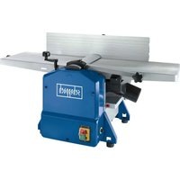
Plana 3.0
| Scope of delivery | |
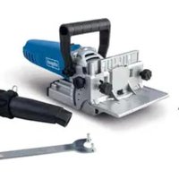
| Planing machine Plana 3.0 | |
| Planer shaft guard | |
| Combined extraction outlet | |
| Assembly supplies (supply bag) | |
| Adjustable planer fence | |
| Operating instructions | |
| Technical Specs | |
| Dimensions L x W x H mm (dimensions with baseframe in brackets) | 1160 x 690 x 720 (1060) |
| Table Height mm | 540 |
| Work Table L x W mm | je 500 x 310 |
| Thicknessing Table L x W mm | 590 x 250 |
| Weight kg | 135 |
| Planer shaft | |
| Planer shafts ø mm | 59 |
| Knife range ø mm | 61 |
| Material of shaft | C45 |
| Speed max. 1/min | 6500 |
| Number of blades | 2 |
| Dimension of blades mm | 3 x 18 x 260 |
| Blade resharpable size mm | 15 |
| Material of blades mm | HSS Nr. 3343 |
| Feeder | |
| No. of feeder cylinders | 2 |
| Surface | gummed |
| Feeder cylinders ø mm | 35,5 |
| Length mm | 307 |
| Feeding speed m/min. | 5,0 |
| detachable | yes |
| Motor | |
| Motor V/Hz | 380-420/50 220-240/50 |
| Receiving capacity P1 W | 2400 2340 |
| Delivering capacity P2 W | 1800 1750 |
| Speed 1/min | 2800 |
| Operation mode | S6/40 % |
| Work data | |
| Planer work width max. mm | 260 |
| Chip work thickness max. mm | 3 |
| Planer thickness width max. mm | 250 |
| Chip thickness max.mm | 5 |
| Aperture thickness min/max. mm | 5/210 |
| Angle | 90-45° |
| Stopper length mm | 900 |
| Stopper height mm | 150 |
| Subject to technical changes! | |
■ SOUND CHARACTERISTICS
In accordance with EN 23746 for sound power level, as well as EN 31202 (correction factor k3 calculated according to Appendix A.2 of EN 31204) for the calculation of the sound pressure level at the workstation, the sound emission values add up to a total below the underlying work conditions mentioned in ISO 7904 Appendix A.
Sound power level in dB (Work)
Idle speed LWA = 93.8 dB (A)
Processing LWA = 100.6 dB (A)
Sound pressure level at the workstation in dB
Idle speed LpAeq = 88.0 dB (A)
Processing LpAeq = 93.7 dB (A)
Sound power level in dB (Thickness)
Idle speed LWA = 94.8 dB (A)
Processing LWA = 97.9 dB (A)
Sound pressure level at the workstation in dB
Idle speed LpAeq = 78.3 dB (A) Processing LpAeq = 84.3 dB (A)
The specified values are emission values and therefore do not have to represent exact work station values at the same time. Although there is a correlation between emis-
sion and immission gages, it is not possible to determine reliably, whether additional precautions are necessary or not. Current factors of the work station affect the immission gages, including the characteristics of the work station, other sound sources, for example number of machines other adjacent operations. The permissible work values can vary from country to country. However, the operator should capacitate the information, in order to make an estimate of the hazard and risk. Information on dust emission In accordance with the policy of the Technical Committee for Wood on dust emission checkup (concentration parameter) of woodworking machines, dust emission values appropriate for wood are below 2 mg/3. As a result, after connecting the machine to an operational dust extraction outlet, with air speed of at least 20 m/s in adherence to the lasting and reliable TRK-marginal values for wood dust, effective in the Federal Republic of Germany, it can be more.
In these operating instructions we've marked the sections that pertain to your safety with this sign: ⚠
⚠️ General safety instructions
- Pass on the safety warnings to all people who will work on the machine.
- The operator must be at least 18 years old. Apprentices must be at least 16 years old and can only work on the machine under supervision.
- Persons operating the machine should not be distracted.
- Keep children away from machines connected to the power system.
- Wear well-fitting clothes. Take off all jewelry, rings and wristwatches.
- Follow all safety and danger warnings on the machine and keep them in legible condition.
- Caution while working: risk of injury to fingers and hands by the rotating cutting tool.
■ STABILITY ASSURANCE
- During assembly, please make sure that the planing machine stands firmly on solid ground.
⚠️ Utilization according to the regulations
- The planing machine is constructed exclusively from offered tools and supplies for wood processing.
- The machine complies with the valid EG machine guidelines.
- The machine is designed for one shift of work, powerontimeS6–40%.
- Follow all safety and danger warnings on the machine.
- Keep all safety and danger warnings on the machine complete and legible.
- When using in an enclosed space, the machine must be attached to an extraction unit.
- To extract the wood shavings or sawdust, the machine must be attached to an extraction unit. The velocity of flow of the connection piece of the extraction unit
must be 20 m/s. Negative pressure 1200 Pa.
-
The automatic switch-on is available as optional equipment.
Type ALV 2 Item Nr. 79104010 230 V /50 Hz Type ALV 10 Item Nr. 79104020 400 V /230 V /50 Hz -
When switching on, the machine runs the extraction automatically after 2-3 seconds delay time. Thus, an
• overload of the safety fuse will be prevented.
• After switching off, the machine runs the extraction for
• 3-4 more seconds and then shuts off automatically. - The left over dust will be sucked out, as required by the Ordinance on Hazardous Substances. This saves electricity and reduces noise. The extraction unit runs
• only during the use of the machine.
- When operating in a commercial area, a deduster must be employed during extraction. Do not disconnect or remove the extraction unit or the deduster while the machine is running.
- Use the machine only when it is in technically sound conditions, as well as in compliance with the law, with awareness of safety and danger according with the operating instructions! Eliminate immediately all unnecessary distraction that could compromise safety!
- The safety, operation and maintenance instructions of the manufacturer, as well as the dimensions given in the technical specs, must be observed.
- The applicable accident prevention regulations and other technical safety rules of general knowledge must be observed.
- The machine must be used, maintained or repaired only by a competent person who can be trusted and is informed of the dangers. The manufacturer will not be responsible for damages resulting from arbitrary alterations to the machine.
- The machine should only be used with the original tools and supplies from the manufacturer.
- All use beyond the instructions counts as noncompliance with the regulations. The manufacturer does not carry any responsibility for damages resulting from such use, the operator will bear all risks on his own.
Assembly
Due to technical reasons, your packed planing machine is not fully assembled.
The planing machine shouldn't be lifted onto the work table!
Setup and adjustment, Fig. 4
The machine stands on 4 adjustable rubber cushions. Balance the unevenness of the floor. Loosen the lower hexagon nut using the key and turn the rubber cushions correspondingly in and out. Tighten the hexagon nut again. (secure the hexagon nut) Attention! Be sure to align the machine by using a level.
If the rubber cushions are displaced, the machine can be bolted into the boreholes in the floor. For utilization with a base frame, dismantle the rubber cushions and screw on the frame.
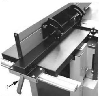
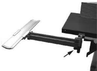
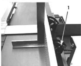
Planer fence, Fig. 5.1
Attach the planer fence to the machine. Set the position to 90^ with the help of a stop angle. Tighten the release handle (1) The planer fence is continuously variably pivoting from 90^-45^ , where the pivoting segment must be loosened. Check each model item with a protractor for dimension accuracy after every angle adjustment.
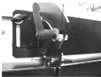
Planer fence setup, Fig. 5.2
Check the 90^/45^ angle and set the cylinder head screws M4x8. 1 = Set screw 90^ angle 2 = Set screw 45^ angle
Attention!
The planer fence must always remain firmly fixed.
Fig. 5.3
The clamping of the planer fence results from the exocentric lever. (1) The planer fence is 260 mm adjustable over the planer.
Attention!
The planer fence must always remain firmly fixed.
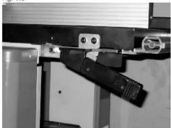
Planer shaft guard, Fig. 5.4
Screw on the planer shaft guard onto a hinged work table. The planer shaft guard can be deviated without a tool by pulling the exocentric lever upwards, swaying the shaft guard, pulling the exocentric lever back down.
Fig. 7 + 8 Attention: Never work with planer fences without the shaft guard.
⚠ Operating Instructions
■ PREPARING AND SETTING UP THE MACHINE
- Changes, setup, measuring and cleaning work on the machine should only be done with the motor turned off. Disconnect the power plug and wait for the shutdown of the rotating tools.
- After repairs and servicing, all protective and safety equipment must be immediately assembled. Immediately exchange defective planer knives (rifts or such). Monitor the knife change! Check the effectiveness of the anti-kickback attachment before each operation. The gripper taper must have a sharp edge. After repairs and servicing, all protective and safety warnings must be immediately mounted onto the machine.
THICKNESS AND WORK
• Maximal planer shaft speed 6500 1/min
- The planer shaft has been manufactured in accordance with DIN EN 847-1.
- Begin the working operation only when the full speed is reached.
- Keep the operator station free of shavings and wood waste.
- Employ the extraction unit for extraction of shavings and wood dust. The velocity of flow of the extraction support must amount to min. 20 m/s.
- Work only with sharpened planer knives. Dull planer knives increase the risk of relapse.
- When processing long work pieces (longer than the feeding table) roll racks (optional equipment) should be employed.
- Work: When dressing a work piece up to 75 mm thick, the planer shaft guard must cover the work piece and the planer shaft from above. If the work piece width is more than 75 mm, set the protective rails of the shaft guard to the width of the work piece. Make sure to put closed hands, with the thumb adjacent on the work piece.
- Joining: The work piece is set against the work stopper. Set the rails of the shaft guard to the width of the work piece and leave on the table.
- Dressing and joining of small cross sections (strips): When dressing the work piece, same as for work pieces up to 75 mm thick, it should be fed with spread out hands. When joining, push the work piece with both hands, with the fists closed, against the help stopper (optional equipment) and feed it through. The guard device is positioned near by and rests on the work piece.
- Dressing and joining of small work pieces: When dressing, push the work piece with spread out hands to the work table and feed through with the pusher, using the right hand. The left hand slides over the guard device, as long as the work piece is on the table the weight of the left hand will shift onto the receiving table. When joining, push the work piece with the left hand, with the fist closed, against the help stopper and the table, then feed through with the pusher.
- Chamfering or beveling: The work piece should be leaned against the work stopper. Set the protective rails of the shaft guard to the width of the work piece and leave the piece on the table. Push the work piece with the left hand, with the fist closed, against the stopper and the receiving table and feed it through with the right hand closed.
BEGINNING
Before starting, observe the safety warnings. All guard and help devices must be installed. Changes, setup, measuring and cleaning work on the machine should only be done with the motor turned off.
Disconnect the power plug!
Planer work - Chip removal, Fig. 6.1
The planer work chip removal is adjustable with the joint lever 1 stepwise from 0 – 3 mm. During work, the thick-nessing table must be adjusted between 90 und 210 mm.
Attention, otherwise the extraction outlet will be clamped!
Fig. 6.2
For longer work pieces (longer than the feeding or the receiving table) a roll rack (optional equipment) or similar should be used.
Planer work – Planer shaft guard, Fig. 7
When dressing up to 75mm work piece strength, the planer shaft guard must cover the work piece and the planer shaft from above. If the work piece width is more than 75 mm, set the protective rails of the shaft guard to the width of the work piece. Make sure to put closed hands, with the thumb adjacent on the work piece.
1 Work stopper
2 Planer shaft guard
Joining, Fig. 8
Use the work stopper for this purpose, leave the planer shaft protector on the table and set the protective rails to the width of the work piece. Push the work piece against the planer stopper and then lead it over the planer shaft with both hands. As long as the board reaches high enough on the receiving table, put the left hand on it and shift it without interruption over the blade shaft.
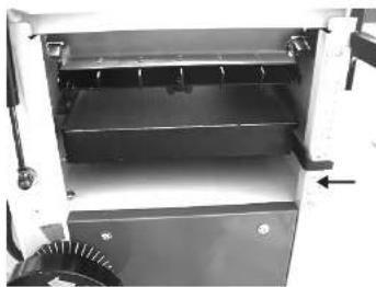
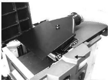
Planer work – Shavings emission, Fig. 9
While work, the work table must be locked. The extraction tube should be connected to the extraction hood. When connected to the extraction unit can then be extracted. Extraction connection caliber 100mm
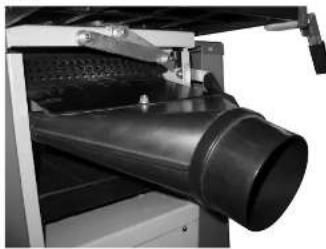
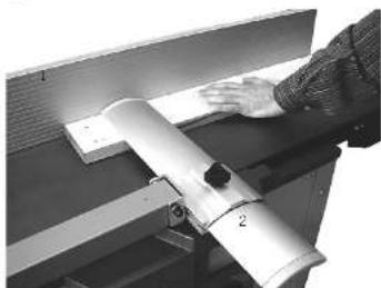
Planer thicknessing - Machine adjustment, Fig. 10.1
Set the work table high and open it. Adjust the height to the highest possible. Set a high pivot and heighten (bolt). Attach the extraction connections and tighten the knurled screw. When connected to the extraction unit can then be extracted.
Planer thicknessing - Table adjustment, Fig. 10.2
The height of the thicknessing table is adjustable by a hand wheel. The integrated position gauge indicates aperture height from 5 to 210 mm.
One rotation of the hand wheel corresponds to 2 mm Keep the thickening table and the work table free of resin. Shaving thickness max. 3 mm. The graduation lines on the graduated collar make a fine adjustment possible, whereby 1 graduation line corresponds to 0, 05 mm.
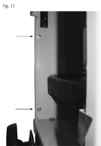
• V-belt tension motor, Fig. 11, 12, 12.1 + 12.2
Warning!
Re-tighten the flat belt and v-belt after the first 3 hours of operation. Then check the belt tension and regularly re-tighten, if necessary, after 40 operating hours.
- Remove 4 hexagon sockets on both inner sides of the encasing, Fig. 11.
- Remove both side walls.
- Losen clamping nut A on both sides (Fig. 13.1 + 13.2).
- Push the motor seesaw down.
• Tighten clamping nut A on both sides. - Attach the side walls.
V-belt feeder cylinders, Fig. 11, 12 + 13.3
- Remove 4 hexagon sockets on both inner sides of the encasing, Fig. 11 + 12.
• Take off the sides.
• Losen 4 hexagon nuts B, Fig. 13.3. - Adjust belt tension.
• Tighten 4 hexagon nuts B. - Loosen the "C" screw, tighten the v-belt, then re-tighten the "C" screw
- Attach the side walls.
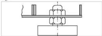
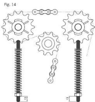
Feeder cylinders adjustment, Fig. 14
To guarantee an efficient feeder the pressure springs must be set to the adjacent dimensions.
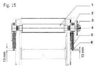
Changing of the feederfeeder cylinder, Fig. 15
The coating of feeder cylinders is from abrasion-resistant rubber. After long-term great operational demand they can suffer from abrasion, which will lead to a change of feeder-feeder cylinder.
1 Feeder cylinder
2 Support clip
3 Chain wheel
4 Spiral pivot
5 Pressure springs
6 Hexagon nut
• Perform the change as follows
- Remove 4 hexagon sockets on both inner sides, Fig. 11 + 12.
• Take off the sides.
• Take off feeder chain.
- Remove feeder cylinder (1) with a hexagon nut (6).
• Transfer the chain wheels to the new feeder cylinder.
• Install the new feeder cylinders.
• At the end, put the machine together again.
■ WORK TABLE SAFETY
To prevent accidental closure of the work table, it is equipped with a hinge shear. When closing the table no special safety precautions need to be taken.
Work table, Fig. 6.1
The planer work chip removal is adjustable with the joint lever 1 in 0 – 3 mm steps.
The work table can get displaced during the time of use and an accurate to dimensions shavings removal is no longer possible. In this case, the hexagon screws need retightening, so that the work table could perform the accurate shavings removal on its own.
⚠️ Residual Risks
The machine is built according to the technical standard and the recognized technical safety regulations. However, certain residual risks can occur while operating.
- Risk of injury for fingers and hands by the rotating planer shaft during improper manipulation of the work piece.
- Injuries by a slipped work piece during improper handling or manipulation, such as working without the stopper.
• Health hazard from dust or wood shavings. - Always wear personal protective equipment, such as eye protection and dust mask. Use the extraction outlet!
- Health hazard from noise. While operating, the noise level will exceed the acceptable. Always wear personal protective equipment, such as ear plugs.
- Hazard from electricity in case of usage of a defective electrical power line.
- Process only selected woods without faults as: knots, cross rifts, surface cracks. Bad wood will lead to risks while operating.
- In addition, obvious residual risks exist despite all precautions taken.
• Residual risks can be minimized by observing the safe-
ty warnings and using the machine in compliance with the regulations, as well as following the operating instructions.
Electrical Connection
- Check power line. Do not use any defective lines. See Electrical Connection.
- Observe the motor and the tool rotation direction. See Electrical Connection Planing Machine
• Installations, repairs and servicing of the electric installation must only be done by an expert professional. - Disconnect the machine to avoid breakdowns. Disconnect the power plug.
- Turn off the motor when leaving the machine. Disconnect the power plug.
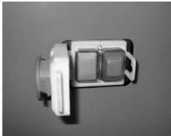
- Disconnect from all power sources even for an insignificant relocation of the machine! Before starting the machine again, connect it properly to the power source! Connect the machine to the power source with a CEEplug, use 16 A to secure the cable. Press the green button on the operating switch, the planer shaft is running (Fig. 2).
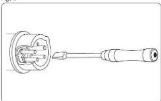
Press the red button to turn off, the planer shaft will slow down within 10 seconds. Changes in rotation direction The rotation direction must be checked when connecting to the power or after moving the machine, if necessary the polarity must be changed using a screwdriver (machine socket, Fig. 3).
The installed electrical motor is connected and ready for use. The connection meet the corresponding VDE and DIN-regulations. The power connection on the part of the client, as well as the extension cables used, must meet EVU-(Electricity Board) regulations.
The electrical motor is sized for S 6/40 % use. S6 = continuous operation with load burden 40% = based on 10 min. 4min. loading; 6min. open-circuit operation The motor shuts down on its own when overloaded, while a winding thermostat is embedded in the motor. After cooling (time can vary) the motor can be switched on again.
■ DEFECTIVE ELECTRICAL POWER LINES
- Often there are isolation defects in electrical power lines. Possible causes:
- Dents, when the power line was installed through a window or doorway.
- Cracks resulting from an improper mound or installation of the power line.
• Cuts from passing around the power line.
• Isolation defects due to pulling out the wall socket. - Rifts because of changes in isolation. Such defective electrical power lines must not be used and are, due to isolation defects life-threatening!
Check the electrical power line regularly for defects. Make sure that the power line is not connected to the power supply system during checkup. The power lines must meet the VDE and DIN-regulations, as well as the local EVE regulations. Use only the power lines with the mark H 07 RN. An identification on the cable of the type of line is mandatory.
Extension cables must be up to 25 m per each 1,5 squared millimeter section, over 25 m long for a section of at least 2,5 squared millimeters. The power connection must be supported by a 16 A fuse.
■ ROTARY MOTOR
Line voltage must be 380 ÷ 420 V 50 Hz. Power connection and extension cabling must be up to 5 cores (5adrig) = 3 P + N + SL.
Extension cables must cover a section of at least 1,5 m2. The power connection should optimally be secured by 16 A.
The rotation direction must be checked after connection to the power or moving the machine, if necessary, the polarity must be changed.
- Connection and repairs of the electrical equipment should only be done by an electrician. For inquiries, please have the following information:
• Motor manufacturer; motor type
• Electrical type of the motor
• The machine/type plate information
• Electrical control system information
When sending back the machine, please include the complete propulsion unit with the electrical control system.
Maintenance
Conduct maintenance, repair and cleaning, as well as malfunction check, only with the unit shut off. Use the on-off switch to shut down the machine and then disconnect from the outlet!
All guard and safety instructions must be immediately mounted after repair and servicing work. The work table, as well as the thickening table must be kept free of resin. You can get Pharmol-HEK resin remover concentrate type Nr. 6100 9700 from your specialist dealer.
Use long-term lubrication for the storage of the planer shaft and the tool spindle. In new conditions, warming is part of the design but it goes away after some time. Clean the feeder cylinders regularly. Oil the bearing and shaft with hinges of the sliding bearing of the feeder cylinders and the adjustment spindle of the thicknessing table after the first 5 hours of operation. After that, oil every 20 hours of operation.
Check the chain tension. If needed, tighten and oil it. When tightening the thicknessing table chain, pay attention to the prallelism of the thicknessing table.
PLANER BLADES
The planer blades at work are beveled and setup correctly, ready for use. Only well-sharpened and exactly set planer blades can guarantee safe operation.
We recommend: Always keep a spare beveled planer blade ready, in need of replacement. You can find a spare planer blade from your specialist Type Nr. 6200 4134.
Feed unit Fig. 13.2 – Warning!
The plastic cogwheels, chain wheels and chains and bolts must be greased every 40 operating hours.
Beveling planer blades
Dull planer blades raise the risk of accidents, the work efficiency is no longer guaranteed. Bevel the blade only up to 15 mm knife height. The blade cutting angle should avarage 40 ± 2 degrees.
For regrinding, bring the blade to an authorised grinding workshop, or ship it back to the manufacturer.
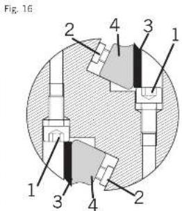
Installing planer blades Fig. 16
1 Adjusting screw
2 Pressure screw
3 Planer blades
4 V-ledge
5 Markings
6 Adjust gauge
Make sure during installation that
• the risk of injury for fingers and hands is mounted.
- the clamping surface in the cutter spindle and the Vledge are clean.
• the beveled planer blades are deoiled.
- only blades that have been beveled in a pair are installed.
- the installation of the planer blades and the V-ledge correspond to the illustration
- close the planer blades and the V-ledge on both sides.
- all of the clamping screws are tightened (8,9 N/m). Warning! The details of blade fastening, blade protection length, blade thickness, should be kept for a minimum during warm up spin and optimally for the starting of the blade attachment screw.
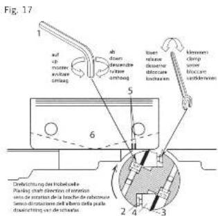
Planer blade adjustment, Fig. 17
• To adjust, apply the provided adjustment gauges.
• First, adjust one blade, then the other.
- Shift the blade on the adjusting screw, alternating sides, till the cutting edge that lies over the work table touches the adjustment gauges.
- The right marking must align, corresponding to the il-During spinning the planer blade must be in sync with the adjustment gauges as much as possible, optimally to the second marking.
- Left and right adjustment should be done following the exterior of the blades.
- Tighten the pressure screws of the V-ledge with a flat wrench SW 8. (8,9 N/m)
- Adjust and clamp the second blade in the same way.
- Perform a test run after each blade change and then retighten the pressure screws. (8,9 N/m)
The planer blade must be tested before use to make sure that the above mentioned instructions have been followed.
Please be attentive of all the safety warnings before turning the machine on.
Declaration of compliance (EU)
Hereby we, the Scheppach Manufacture of Woodworking Machines GmbH, Günzburger Str. 69, D-89335 Ichenhausen, declare that the subsequent qualified machine by way of its construction and design as well as commercial use meets the corresponding regulations of the EG-guidelines stated below. In case of a modification of the machine this declaration is no longer valid.
The machine corresponds to the tested sample.
Name of the machine:
Thicknessing and Planing machine
Type of machine
Plana 3.0, Art.-Nr. 1902202901, 1902202902, 1902202903
Relevant EC directives:
EC machine directive 2006/42/EG,
EC Low voltage directive 2006/95/EWG,
EC-EMV directive 2004/108/EWG.
Applied harmonized European standards:
EN 55014, EN 55104, EN 60555-2, EN 60204-1, EN 861, EN 847-1, EN 12100-2
Notified body:
Technical Committee on Wood, 70504 Stuttgart; Checking and certifying body BG-Approval certificate
Place, Date:
Werner Hartmann (Head of technical Innovation - documentation representative)
| Trouble shooting | ||
| To repair faults, switch off the machine. Pull power plug. | ||
| Irregular and discontinuous transport at the thickness planing | Thickness desk not free of resin or not free of oil. | Clean and spray (sliding spray) the thickness desk regularly. This is valid especially for wet and resinous woods. |
| Workpiece shoulder at the planing | This is due to badly adjusted planer knives. | The adjustment of the planer knives has to be carried out with a lot of care with help of the adjustment gauge. |
| Workpiece inaccuracy at the planing (concave, convex) | At not exactly parallel standing trimming desks due to improper transport or similar. | Adjust the stiff trimming desk 1 mm above the planing shaft body, as well as parallel to the bottom plate. |
| Electrotechnical maintenance only by electric specialists! | ||
| At waste disposal of the machine all the local legal regulations have to be kept. | ||
FABRICANT:
Scheppach
Günzburger Straße 69
D-89335 Ichenhausen
CHER CLIENT,
Nos recommendations:
Directive CE-EMV 2004/108/EWG.
i.V. Werner Hartmann (Head of technical Innovation - documentation representative)
Günzburger Straße 69
D-89335 Ichenhausen
Gentile Cliente,
PIALLA A SPESSORE E A FILO
pp. Werner Hartmann (Head of technical Innovation - documentation
representative)
Stationär LpAeq = 88,0 dB (A)
Bewerking LpAeq = 93,7 dB (A)
Geluidsprestatieniveau in dB (diktes)
Vrijloop LWA = 94,8 dB (A)
■ SCHOLING VAN DE PERSOON,
■ DIE DE MACHINE BEDIENT
p.p. Werner Hartmann (Head of technical Innovation - documentation representative)
Fouten opsporen
Günzburger Straße 69
D-89335 Ichenhausen
■ APRECIADO USUARIO,
i.V. Werner Hartmann (Head of technical Innovation - documentation representative)
Günzburger Straße 69
D-89335 Ichenhausen
INFORMAÇÕES AO USUÁRIO
i.V. Werner Hartmann (Head of technical Innovation - documentation representative)
Detector de avarias
Günzburger Straße 69
D-89335 Ichenhausen
KÆRE KUNDE,
Tomgang LpAeq = 88,0 dB(A)
Günzburger Straße 69
D-89335 Ichenhausen
KUNDEVERDI
Ved installering, sørg for at
Technical Committee on Wood, 70504 Stuttgart; Checking and certifying body BG-Approval certificate
Sted, Dato:
i.V. Werner Hartmann (Head of technical Innovation - documentation representative)
Feilsøking
Günzburger Straße 69
D-89335 Ichenhausen
ARVOISA ASIAKAS,
i.V. Werner Hartmann (Head of technical Innovation - documentation representative)
Vienetsintä
i.V. Werner Hartmann (Head of technical Innovation - documentation representative)
Günzburger Straße 69
D-89335 Ichenhausen
Günzburger Straße 69
D-89335 Ichenhausen
SPOŠTOVANA STRANKA,
Želimo Vam veliko veselja in uspeha pri delu z Vašo novo napravo Scheppach.
Nasvet:
Prosti tek LpAeq= 88,0 dB (A)
Obdelava LpAeq= 93,7 dB (A)
Günzburger Straße 69
D-89335 Ichenhausen
SZANOWNI PAŃSTWO
Technical Committee on Wood, 70504 Stuttgart; Checking and certifying body BG-Approval certificate
Miejsce, Data:
Günzburger Straße 69
D-89335 Ichenhausen
VÁŽENÝ ZÁKAZNÍKU
Günzburger Straße 69
D-89335 Ichenhausen
VÁŽENÝ ZÁKAZNÍK
1 = 02798520
2 = 307 4603 1002
3 = 307 4603 1001
4 = 0500 5401
5 = 0201 2504
6 = 307 4603 0004
7 = 0209 1236
8 = 307 4603 0003
9 = 307 4603 2001
10 = 307 4603 2002
11 = M6
12 = M 5
Only for EU countries. The operational electric laser together with associated mode residual in observation of capacitor direct to 20.06/95/EC or neural electrical and electronic circuit and its implementation in accordance with national law, electric tools that have issued the end of their life must be selected separately and returned to an environmentally compatible recycling facility.
P12012

This appliance is covered by a 24 month's guarantee
- The guarantee covers only material and recombination parts. Lavity parks are replaced with
2014, 2015 and 2016 are the first year of the year. The following is only one year.
- The gamma-theta valorian Transcr. damp, are nguts, damp manual inglns
improve use of before to observe existing instructions, electrical fault or electrical
regular cars are not observed.
- Guarantee claims are valid only if no repairs have been made by a third party. The warranty per issue is only valid with the expense.
Barrle FRANCE
1.24.1-derivate to per unit level, sequeite
Gorilla - ITALIA
Per quest'apparecchi: clamo una garancia d'21 mes
onso: cranbes, pinnarwels, (a) eoli to: a) a) eil
-
In our case, the first part of this is a result in a consensus
-
La JESCA LE TOT LEA DE LA BARRA, LA ZAFI PARAN, LA CAJA, LA LA PRAPOL, LA LA PARELA, LA LA CARRA, LA LA ZAFI PARAN, LA LA CAJA, LA LA PRAPOL, LA LA ZAFI PARAN, LA LA CARRA, LA LA ZAFI PARAN, LA LA ZAFI PARAN, LA LA ZAFI PARAN, LA LA ZAFI PARAN, LA LA ZAFI PARAN, LA LA ZAFI PARAN, LA LA ZAFI PARAN, LA LA ZAFI PARAN, LA LA ZAFI PARAN, LA LA ZAFI PARAN, LA LA ZAFI PARAN, LA LA ZAFI PARAN, LA LA ZAFI PARAN, LA LAZARARARARARARARARARARARARARARARARARARARARARARARARARARARARARARARARARARARARARARARARARARARARARARARARARARARARARARARARARARARARARARARARARARARARARARARARARARARARARARARARARARARARARARARARARARARARARARARARARARARAR
2017/03/06 19:45 18:45 18:45 18:45 18:45 18:45 18:45 18:45 18:45 18:45 18:45 18:45 18:45 18:45 18:45 18:45 18:45 18:45 2017/03/06 19:45 18:45 18:45 18:45 18:45 18:45 18:45 18:45 18:45 18:45 18:45 18:45 18:45 18:45 2017/03/06 19:45 19:45 19:45 19:45 19:45 19:45 19:45 19:45
1.2.3 (yctm 2A) (g) is a 0.5% (p = 0.4, p < 0.01), and the
Gorilla - ESPAÑO
- Ma to create a program in case de para de depots, then, re-terrestre, then
Egromine (Bilir) is a major role in the
二、编制日期:2017年5月4日
-34.150mlckio
vahinkop, gltis, jchuvat koneen, v31-425 syltens ta es, cle roudredu koneen khybonyjella
- 10727 - 10110153a hui umisza
- 2016, 1984-2015.473
- 10.0000
Takuradistus on velinosa seil zebuutti 60%
E-mail: 90165
ENTH - NOTE
På dene merderer gr at 76 minrader, geordi.
-
Gesetzen in bedelten water-poleter (dark waterpole). Dena man lat zle neareded idra
-
2017年,美国注册商标(以下简称“商标”)的专利申请及专利权属证书(以下简称“商标”)。
-
Sachten anderer Ide: Urester, interpedrade, State-träuter, w. harrigaler
afors-ktig brull.
- Sevelina afi bao impodermal saloral peregrise iba at aljat na isbeljuntis.
Figuristics, for basic guidelines, the following methods
Evans - OWNER
På dette maskite jörder si Dem 24 månecers garand.
-
Corollary about the
-
In fact, the following text in the image is: "The text in the image is not explicitly written in the source image."
-
Fasidere kan sarrilized iu suu grider
-
We have been given a matter of the general basis for the same time, the last year is a large positive moment for men in the space.
Sevlerer, or kurslyj i ostrato real aktura
Bryssitz, 1985
(1) 2014年1月1日
Ltru is lonanlava 24 hizrognol (Pillet) zitazovici lncane Lark. Littek. 1. A filte klinatlanogon an ovesk, da quinisi holoja roder a. A technoderm disneket
- A. K. K. K. K. K. K. K. K. K. K. K. K. K. K. K. K. K. K. K. K. K. K. K. K. K. K. K. K. K. K. K. K. K. K. K. K. K. K. K. K. K. K. K. K. K. K. K. K. K. K.
scherpach-reszelné calatunk zraiket
- Semmäte, aktien gängs (lehkelag, can el externa ochelbe andelben, asitiven)
cink, a hauwendel, muzuk, xuicomilien hauwendel sotumus kure, andem al.
zumredezes um black hyazhely local Insgyban, ze erklintiviz laizandizis u szeke.
E VSE - Mananahjero 4.00. EVA 2174-DE 615. DUCONNA BONZANAHJER GPECH ukli hnuwasa
A particle characteristics can be obtained from the
Garancia - SLOVARELI
-
-
-
-
- 10.
-
-
-
-
A small number of m is a large number of m, and the number of m is a large number of m.
unrecognii deacijih prezas VDE-cantla (10C,0N 57113*9D0*13
- Osim toga ac mogu garancijski zamjevi za pribor surne na vozom e nacraviti, koji se od
kzu postrallid refe osobe.
Gaznola sama ima vrijednost u vezarjem na rstuncem.
Gurancio - SLOWENIER
Za na pena zva van u di po 24 peasitno peasite
-
Models who allow a specific model to be used. With the connection task
-
N### (###) 2016-2017: 1 quarter (4-8 p.m. 25-2016, Nov., 8 [11/12], Oct. 19)