ISU-WOOL-2B - Cutting machine MSW - Free user manual and instructions
Find the device manual for free ISU-WOOL-2B MSW in PDF.

| Product Type | Mineral Wool Cutting Machine |
| Brand | MSW |
| Model | ISU-WOOL-2B |
| Weight | 14,25 kg |
| Compatible Materials | Wood fiber panels, rock wool, polyurethane foam |
| Frame | Lightweight aluminum |
| Recommended Use | With reciprocating saw or hand saw |
| Safety | Wear closed clothing, respirator, safety goggles and protective gloves |
| Cleaning | Dry cloth, do not use solvents |
| Maintenance | Check tightness of nuts and bolts before each use; check blade sharpness |
| Thickness adjustment function | Yes, via adjustable press plate |
| Limit block | Yes, to position the blade above the plastic roller |
| Wall support | Yes, with wall support post and square tubes |
| Magnetic knife | Yes, integrated into the press plate |
| Integrated rulers | Left and right ruler |
| Knurled handle | Yes, for handling |
| Compression rod | Yes, with handle |
| Included panels | Left and right |
| Knife holder | Magnetic |
Frequently Asked Questions - ISU-WOOL-2B MSW
User questions about ISU-WOOL-2B MSW
0 question about this device. Answer the ones you know or ask your own.
Ask a new question about this device
Download the instructions for your Cutting machine in PDF format for free! Find your manual ISU-WOOL-2B - MSW and take your electronic device back in hand. On this page are published all the documents necessary for the use of your device. ISU-WOOL-2B by MSW.
USER MANUAL ISU-WOOL-2B MSW
natural_image
Technical diagram of a vertical metal frame structure with an arrow pointing to a numbered component (no text or symbols present)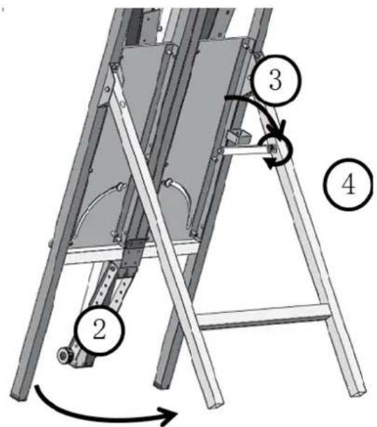
A- Block begrenzen
This User Manual has been translated for your convenience using machine translation. Reasonable efforts have been made to provide an accurate translation; however, no automated translation is perfect nor is it intended to replace human translators. The official User Manual is the English version. Any discrepancies or differences created in the translation are not binding and have no legal effect for compliance or enforcement purposes. If any questions arise related to the accuracy of the information contained in the User Manual, please refer to the English version of those contents which is the official version.
Technical data
| Parameter description Parameter value | |
| Product name Mineral Wool Cutting Machine | |
| Model | MSW-ISU-WOOL-2B |
| Weight [kg] 14.25 | |
Description
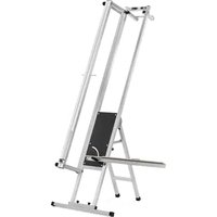
This product is designed for cutting insulation materials such as wood fibre, rock wool, and foam polyurethane boards. Built with a lightweight aluminium frame, it can be used with a reciprocating saw or hand saw for precise cutting of these materials.
The user is liable for any damage resulting from unintended use of the device.
Operation
This machine should only be operated by trained personnel who are knowledgeable about its use. It is advised to wear proper protective gear, including closed work clothing, respirators, safety goggles, and protective gloves.
1. Operation steps
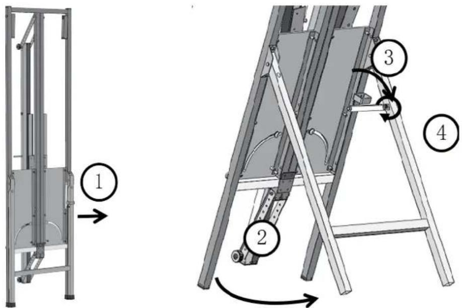
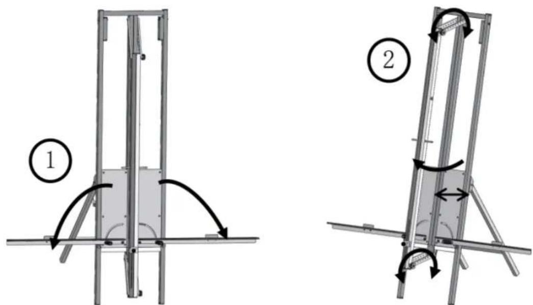
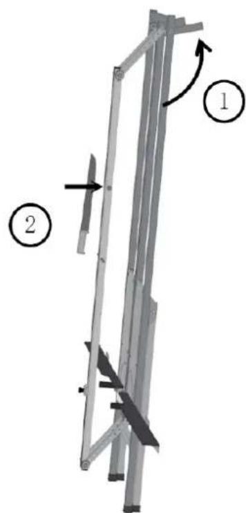
1) Take the machine out of the carton, loosen the Velcro, and unfold the back stand. Then hang the hook, tighten the screws.
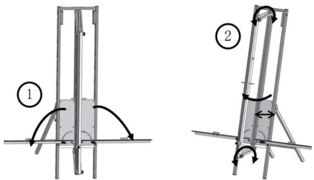
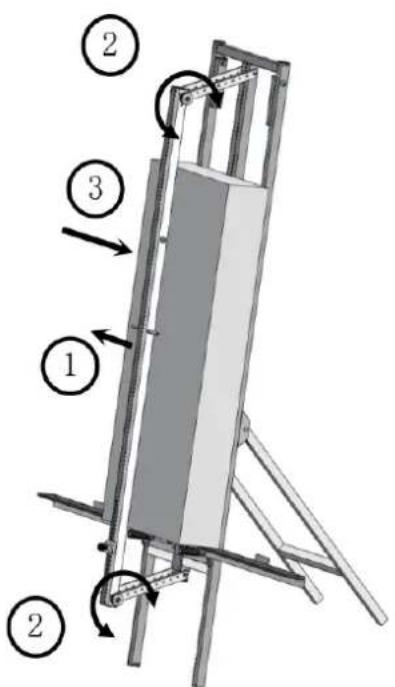
2) Unfold the left & right ruler and secure the press plate by tightening the upper and lower screws, adjusting them based on the material's thickness. Ensure the gap between the press plate and the board is slightly larger than the thickness of the material.
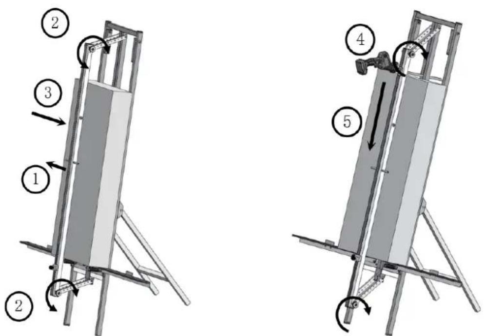
3) Place the material in position, then loosen the upper and lower screws of the press plate, allowing it to compress the material. Once the material is secured, tighten the screws again. Then to cut the material with a hand saw.

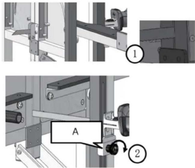
A- Limit block
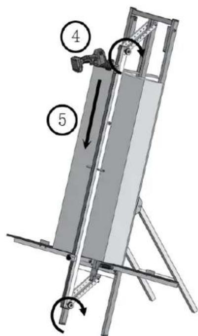
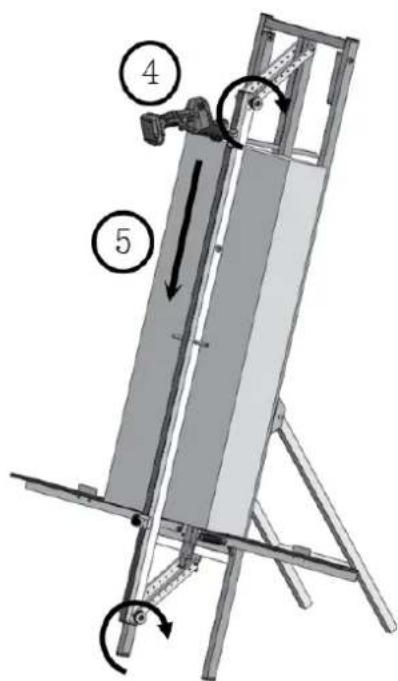
4) When using the electric saw, adjust the position of the limit block before cutting to ensure that the blade is positioned higher than the plastic roller. This prevents the blade from touching the plastic roller when cutting through the material.
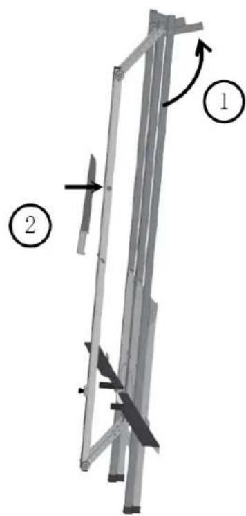
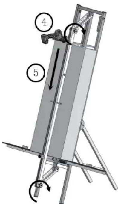
5) When operating the device against a wall, unfold the two square tubes and position them at an angle to secure the device. Once stable, proceed with the cutting. The mineral wool knife can be held in place on the press plate using the built-in magnet.
- Shapes to be cut
| Rectangle |  |
| Ladder-shaped Triangle |  |
Cleaning and maintenance
Before each use, inspect all nuts and bolts, tightening them as needed. Additionally, check the sharpness of the blade or saw, as dull tools can lead to injury. If the sharpness is uncertain, replace the blade or saw.
Clean the tool with a dry medium and avoid using any solvents.
Parts diagram
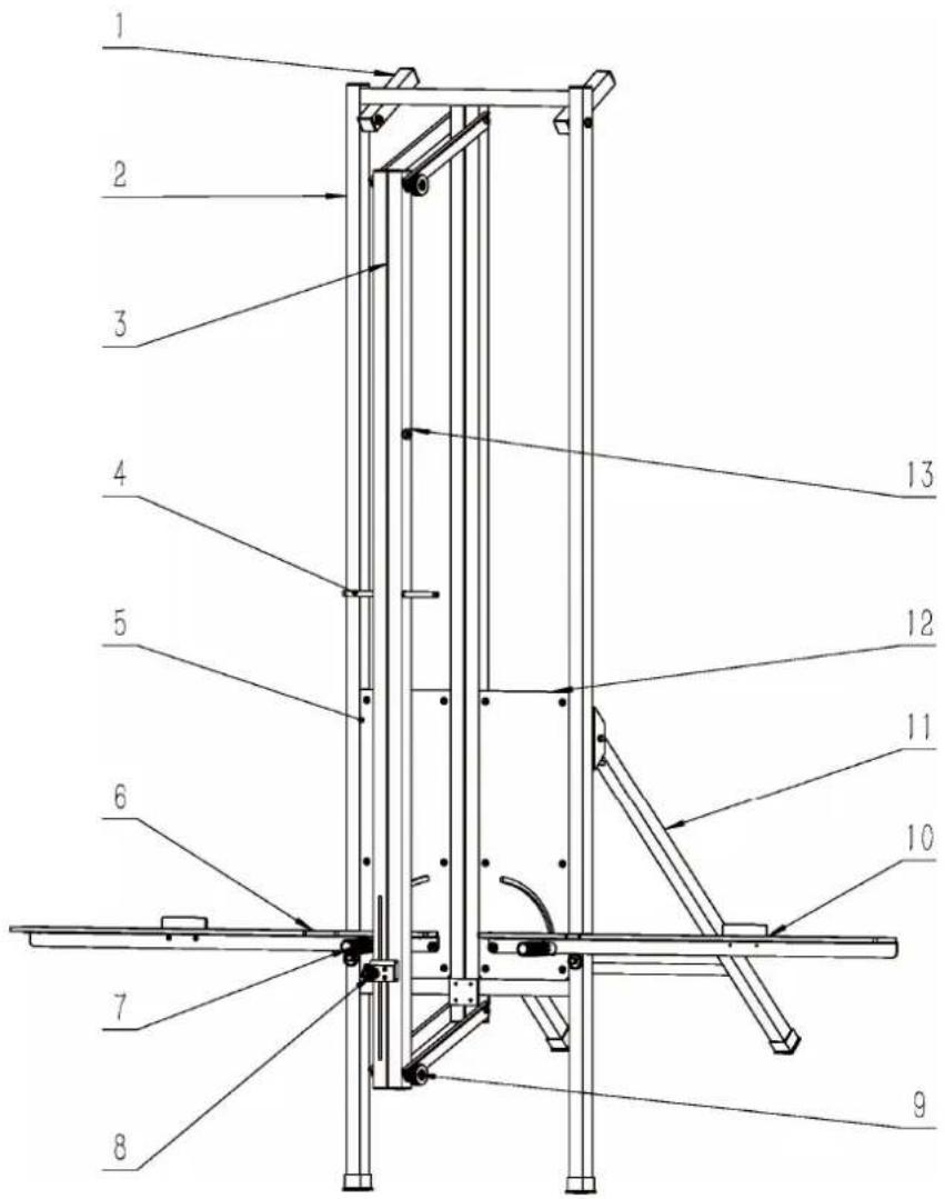
Part number Description
| 1 | Wall-mounted |
| 2 | Support |
| 3 Downward compression rod | |
| 4 Downward compression rod handle | |
| 5 | Left |
| 6 Left ruler assembly | |
| 7 | Ribbed |
| 8 Reciprocating saw limitation component | |
| 9 | Adjustable |
| 10 Right ruler assembly | |
| 11 Back brace rod | |
| 12 | Right |
| 13 Knife rack magnet | |
| support |
| bracket |
| panel |
| handle |
| nut |
| panel |

natural_image
Mechanical lifting device with metal frame and labeled component (no text or symbols)
A- Ogranicznik

A- Limitní blok

natural_image
Mechanical lifting device with metal frame and labeled component (no text or symbols on the device itself)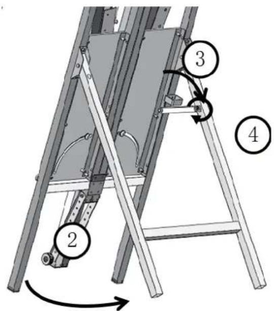
A- Blocco limite
natural_image
Mechanical lifting device with metal frame and labeled component (no text or symbols on the device itself)
A- Grænseblok
A- Rajoituslohko
natural_image
Mechanical assembly diagram showing a vertical frame with curved arrows indicating motion or force direction (no text or symbols)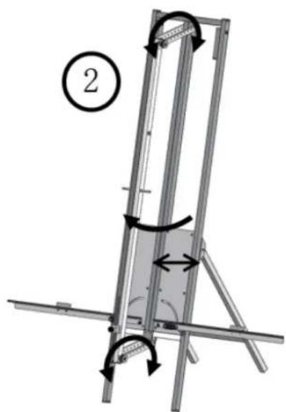
natural_image
Diagram of a metal frame structure with rotational arrows indicating motion, no text or symbols present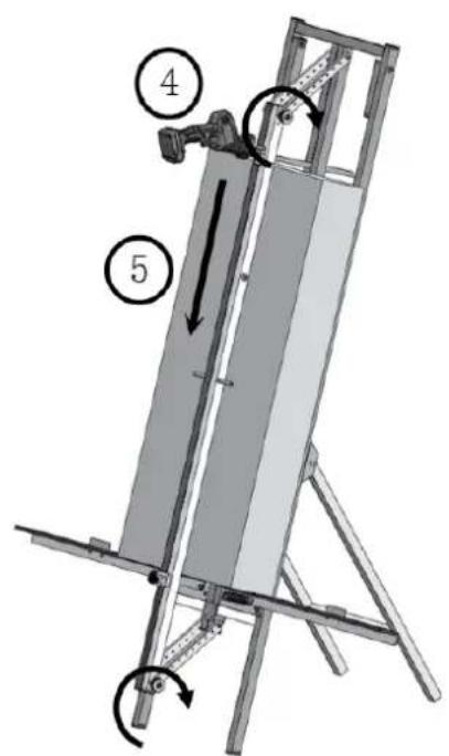
natural_image
Mechanical lifting frame with metal frame and structural supports, labeled with number 1 (no text or symbols on the frame itself)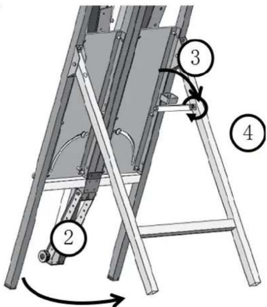
A- Begränsa block
natural_image
Mechanical lifting device with metal frame and labeled component (no text or symbols on the device itself)
A- Limitný blok
natural_image
Mechanical lifting frame with metal frame and labeled component (no text or symbols)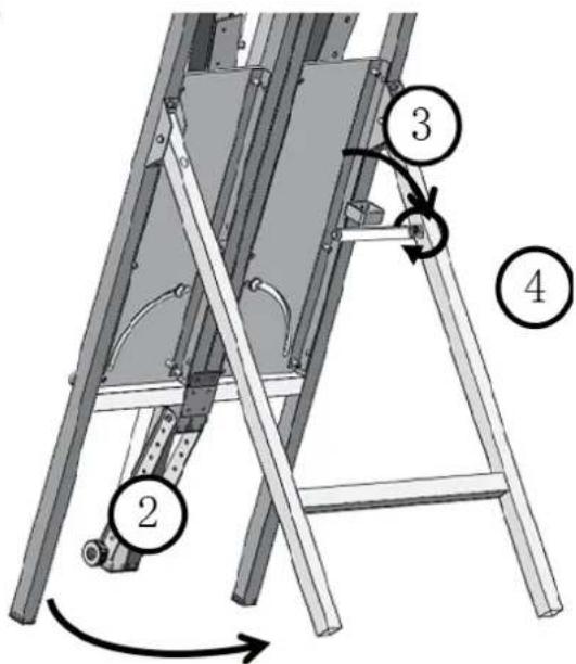

1) Izvadite stroj iz kutije, olabavite čičak i rasklopite stražnji stalak. Zatim objesite kuku, zategnite vijke.
2) Otklopite lijevo i desno ravnalo i pričvrstite pritisnu ploču zatezanjem gornjih i donjih vijaka, prilagođavajući ih ovisno o debljini materijala. Provjerite je li razmak između pritisne ploče i ploče malo veći od debljine materijala.
3) Postavite materijal na mjesto, zatim otpustite gornje i donje vijke pritisne ploče, dopuštajući joj da stisne materijal. Nakon što je materijal pričvršćen, ponovno zategnite vijke. Zatim rezati materijal ručnom pilom.
A- Ograničiti blok
4) Kada koristite električnu pilu, podesite položaj graničnog bloka prije rezanja kako biste bili sigurni da je oštrica postavljena više od plastičnog valjka. Time se sprječava da oštrica dodiruje plastični valjak prilikom rezanja kroz materijal.
A- Ribinis blokas
natural_image
Mechanical lifting device with metal frame and labeled component (no text or symbols on the device itself)
A- Blocare limită

A- Mejni blok
For the disposal of the device please consider and act according to the national and local rules and regulations.
CONTACT
expondo Polska sp. z o.o. sp. k.