GP-110 - Water pump MSW - Free user manual and instructions
Find the device manual for free GP-110 MSW in PDF.

| Product type | Gasoline water pump |
| Model | MSW GP-110 |
| Dimensions (L x W x H) | 560 x 450 x 430 mm |
| Weight | 23 kg |
| Connection diameter (inlet/outlet) | 80 mm / 80 mm |
| Maximum capacity | 60 m³/h (60,000 L/h) |
| Maximum lift height | 28 m |
| Maximum suction height | 8 m |
| Engine type | 1-cylinder 4-stroke gasoline, OHV, air-cooled, compression ratio 8.5:1, recoil starter, Euro 5 |
| Displacement | 210 cm³ |
| Maximum power | 5.2 kW / 7 hp at 3600 rpm |
| Maximum torque | 14 Nm at 2500 rpm |
| Fuel type | Unleaded gasoline min 95 octane (RON) |
| Fuel tank capacity | 3.6 L |
| Engine oil volume | 0.6 L |
| Fuel consumption | ~2.42 L/h |
| Engine oil type | SAE 10W30-40 or 15W30-40 |
| Spark plug / gap | F6RTC (or equivalent) / 0.7-0.8 mm |
| Sound pressure level (LpA) | 88.5 dB(A) (uncertainty K=) |
| Sound power level (LwA) | 109 dB(A) (uncertainty K=) |
| Power source | Gasoline, thermal engine |
| Main functions | Clear water pumping, irrigation, drainage, transfer |
| Maintenance and cleaning | Oil change every 300 h or 6 months, air filter cleaning, spark plug inspection |
| Safety | Emergency stop via switch, thermal protection, outdoor use only |
| Spare parts and repairability | Spare parts available through manufacturer after-sales service, repair by qualified personnel |
| General information | Warranty and support via dealer, manual available in multiple languages |
Frequently Asked Questions - GP-110 MSW
User questions about GP-110 MSW
0 question about this device. Answer the ones you know or ask your own.
Ask a new question about this device
Download the instructions for your Water pump in PDF format for free! Find your manual GP-110 - MSW and take your electronic device back in hand. On this page are published all the documents necessary for the use of your device. GP-110 by MSW.
USER MANUAL GP-110 MSW
natural_image
Technical line drawing of a mechanical component with no visible text or symbols

natural_image
Illustration of a mechanical device with hoses and components (no text or symbols)natural_image
Close-up of a hand inserting a black plastic plug into a white mechanical component (no text or symbols visible)natural_image
Close-up of a yellow industrial fan or pump with black adjustment knobs and a 'MISUY' logo (no readable text beyond branding)natural_image
Close-up of a mechanical assembly with visible components and a red arrow pointing to a yellow safety stripe (no text or symbols)natural_image
Close-up of a blue automotive engine component with black hoses and yellow background (no visible text or symbols)natural_image
Line drawing of hands holding a device with a circular button and connector (no text or symbols)natural_image
Diagram of a mechanical assembly with layered components and a tool, no visible text or symbols3.5 Fehlerbehebung
This User Manual has been translated for your convenience using machine translation. Reasonable efforts have been made to provide an accurate translation; however, no automated translation is perfect nor is it intended to replace human translators. The official User Manual is the English version. Any discrepancies or differences created in the translation are not binding and have no legal effect for compliance or enforcement purposes. If any questions arise related to the accuracy of the information contained in the User Manual, please refer to the English version of those contents which is the official version.
Technical data
| Parameter description | Parameter value | |
| Product name | Gasoline water pump | |
| Model | MSW-GP-100 | MSW-GP-110 |
| Dimensions [Width x Depth x Height; mm] | 500 x 400 x 400 | 560 x 450 x 430 |
| Weight [kg] | 22 | 23 |
| Water connection diameter - inlet/outlet [mm] | 50 / 50 80 / 80 | |
| Maximum engine speed [rpm] | 3600 | |
| Maximum capacity [m3/h or L/h] | 25 / 25000 | 60 / 60000 |
| Maximum lifting height [m] | 25 28 | |
| Maximum suction height [m] | 8 | |
| Engine type | 1-Cylinder 4-stroke petrol, OHV, air-cooled, compression ratio 8.5:1, recoil starter, Euro 5 | |
| Engine displacement [cm3] | 210 | |
| Maximum engine power [kW/KM] | 5.2/7 at 3600 rpm | |
| Maximum torque [Nm] | 14 at 2500 rpm | |
| Fuel type | Unleaded petrol min 95 octane (RON) | |
| Fuel tank capacity [L] | 3.6 | |
| Engine oil system volume [L] | 0.6 L | |
| Fuel consumption [L/h] | ~2.42 | |
| Oil type | for 4-stroke gasoline engines SAE 10W30-40 or 15W30-40* with cleaning additives | |
| *Standard application temperature conditions. In the case of extremely cold conditions below - 20°C, recommended SAE 10W30 with cleaning additives | ||
| Spark plug type / electrode gap [mm] | F6RTC (or equivalent) / 0.7-0.8 | |
| Sound pressure level LpA / Measurement uncertainty K= [dB(A)]. | 88.5 | |
| Sound power level LwA / Measurement uncertainty K= [dB(A)] | 109 | |
1. General description
The user manual is designed to assist in the safe and trouble-free use of the device. The product is designed and manufactured in accordance with strict technical guidelines, using state-of-the-art technologies and components. Additionally, it is produced in compliance with the most stringent quality standards.
DO NOT USE THE DEVICE UNLESS YOU HAVE THOROUGHLY READ AND UNDERSTOOD THIS USER MANUAL.
To increase the product life of the device and to ensure trouble-free operation, use it in accordance with this user manual and regularly perform maintenance tasks. The technical data and specifications in this user manual are up to date. The manufacturer reserves the right to make changes associated with quality improvement. The device is designed to reduce noise emission risks to a minimum, taking into account technological progress and noise reduction opportunities.
Legend
C ∈
The product satisfies the relevant safety standards.
 | Read instructions before use. |
 | The product must be recycled. |
 | WARNING! or CAUTION! or REMEMBER! Applicable to the given situation.(general warning sign) |
 | Use ear protection. Exposure to loud noise may result in hearing loss. |
 | Wear protective goggles. |
 | Wear protective gloves. |
 | Wear foot protection. |
 | ATTENTION! Loud noise warning! |
 | ATTENTION! Fire hazard - flammable materials! |
 | WARNING! Toxic substances, danger of poisoning! |
 | ATTENTION! Hot surface, risk of burns! |
 | Do not smoke in the vicinity of the unit. The unit contains flammable substances. |
 | Use only in open, well-ventilated spaces. |

PLEASE NOTE! Drawings in this manual are for illustration purposes only and in some details may differ from the actual product.
2. Usage safety
CAUTION! Read all safety warnings and all instructions. Failure to follow warnings and instructions could result in serious injury or even death.
The term "unit" or "product" in the warnings and in the description of the instructions refers to:
Gasoline water pump
2.1. Safety in the workplace
a) Keep the work area tidy and well lit. Disorder or poor lighting can lead to accidents. Be foresighted, watch what you are doing and use common sense when using the unit.
b) Do not use the unit in an explosive area, for example in the presence of flammable liquids, gases or dust. The unit produces sparks that can ignite dust or fumes.
c) If you find any damage or irregularities in the operation of the unit, immediately turn it off and report it to an authorized person.
d) Only the manufacturer's service department may repair the unit. Do not carry out repairs yourself!
e) In case of open flames or fire, use only dry powder or snow (CO2) fire extinguishers to extinguish the live equipment.
f) No children or unauthorized persons are allowed in the work area. (Inattention may result in loss of control of the unit.)
g) Use the unit in a well-ventilated area.
h) Check the condition of the safety stickers regularly. Replace them if they are illegible.
i) Keep these instructions for use for future reference. If the unit is to be passed on to a third party, the operating instructions must also be handed over together with the unit.
j) Keep the packaging and small assembly parts out of the reach of children.
k) Keep the unit away from children and animals.
I) When using this unit together with other units, also follow the other instructions for use.

Please note! Keep children and other bystanders safe while operating the unit.
2.2. Personal safety
a) Do not operate this unit if you are tired, ill or under the influence of alcohol, drugs or medication that could impair your ability to operate the unit.
b) The unit may be operated by persons who are physically fit, capable of operating it and appropriately trained, and who have read this instruction manual and have been trained in occupational safety and health.
c) The machine is not intended to be used by persons (including children) with reduced mental, sensory or intellectual functions or persons who lack experience and/or knowledge unless they are supervised or have been instructed by a person responsible for their safety on how to operate the machine.
d) Use caution and common sense when operating this unit. A moment's inattention during operation may result in serious personal injury.
e) Use personal protective equipment as required when operating the unit as specified in Section 1 of the explanation of symbols.
The use of appropriate, approved personal protective equipment reduces the risk of injury.
f) To prevent accidental start-up, make sure the switch is in the off position before connecting to a power source.
g) Before switching the unit on, remove any regulating tools or keys. Any tools or keys left in the rotating part of the unit may cause injury.
h) The unit is not a toy. Children should be watched to ensure that they do not play with the unit.
i) Do not place your hands or any objects inside the running unit!
2.3. Safe use of the unit
a) Do not overload the unit. Use tools that are suitable for the application. A correctly selected unit will do a better and safer job for which it was designed.
b) Do not use the unit if the ON/OFF switch does not function properly (does not turn on and off). Units that cannot be controlled by the switch are unsafe, cannot operate, and must be repaired.
c) Unplug the unit before making adjustments, changing accessories, or putting it away. This precaution reduces the risk of accidental start-up.
d) Keep the unit in good working condition. Check before each use for general damage or damage to moving parts (cracks in parts and components or any other condition that may affect the safe operation of the unit). If damaged, have the unit repaired before use.
e) Keep the unit out of the reach of children.
f) Repairs and maintenance should be carried out by qualified personnel using only original spare parts. This will ensure the safety of use.
g) To ensure the designed operational integrity of the unit, do not remove factory-installed covers or loosen screws.
h) When transporting or moving the unit from storage to the place of use, observe the health and safety rules for manual handling applicable in the country where the unit is used.
i) Avoid situations in which the machine stops under heavy loads during operation. This can cause overheating of the drive elements and consequent damage to the equipment.
j) Do not move, shift, or rotate the machine while in operation.
k) Do not leave the unit switched on unattended.
I) Clean the unit regularly to prevent permanent dirt build-up.
m) The provided value of vibration emission is measured according to the standard measurement methods. The value of vibration emission may change if the unit is used under different environmental conditions.
n) Before each use, make sure that the nozzle is properly mounted in the machine and that the hose is properly attached and undamaged.
o) Do not obstruct the air inlet or outlet.
p) The unit is not a toy. Cleaning and maintenance must not be performed by children without adult supervision.
q) Do not start up an empty unit.
r) Do not tamper with the unit to alter its performance or design.
s) Keep the unit away from sources of fire and heat.
t) Do not overload the unit.
u) Do not block the ventilation openings of the unit!
v) Use of the pump to pump saltwater, corrosive substances, flammable liquids, etc. is prohibited.
w) Add oil to the proper level before turning on the machine. If the oil level is too low the engine will not start or may shut down. Running an engine with too low engine oil level may cause it to fail.
x) Report any leakage of operating oils from the machine to the relevant authorities or comply with the legal requirements in your area of use.
y) Danger! Health hazard and risk of explosion of the combustion engine.
z) The engine exhausts contain poisonous carbon monoxide. Remaining in an environment containing carbon monoxide can lead to unconsciousness or even death. Do not run the engine in an enclosed area.
aa) Keep the engine away from heat, sparks and flame. Do not smoke near the machine!
bb) Gasoline is flammable and explosive. Stop the engine and let it cool down before refueling.
cc) Caution! Wrong fuel may cause damage to the engine.

ATTENTION! Despite the safe design of the device and its protective features, and despite the use of additional elements protecting the operator, there is still a slight risk of accident or injury when using the device. Stay alert and use common sense when using the device.
3. Use guidelines
The unit is designed for pumping water.
The user is responsible for any damage resulting from misuse.
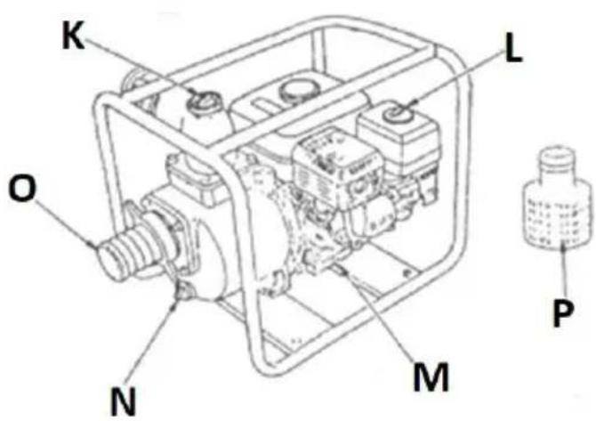
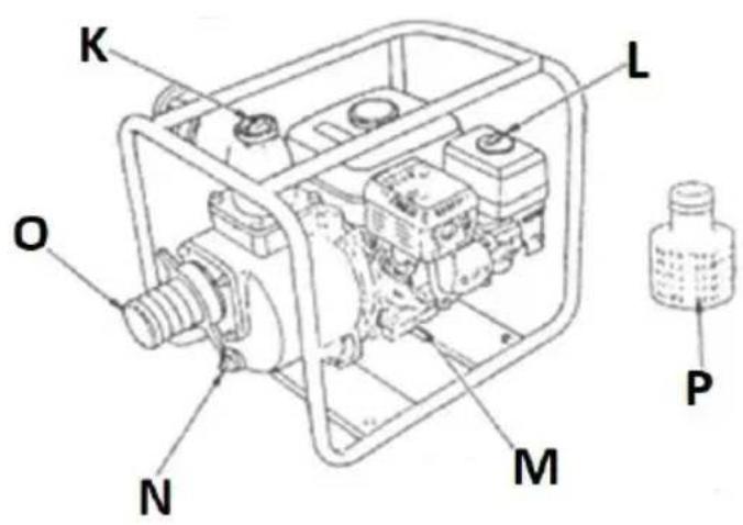
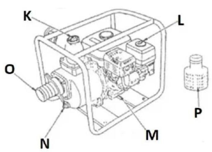
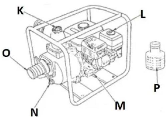
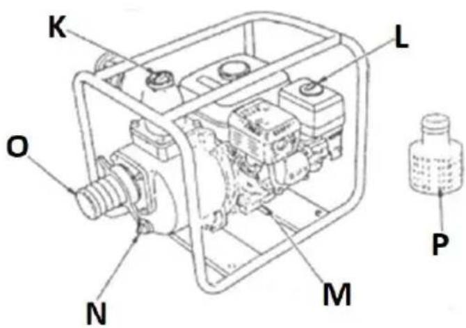
3.1. Device description
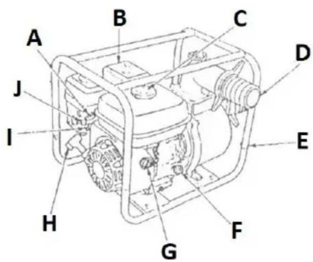
A. Throttle lever
B. Muffler
C. Tank filler cap
D. Water outlet end
E. Frame
F. Engine oil filler cap (with dipstick)
G. Ignition switch
H. Recoil starter handle
I. Fuel valve
J. Choke control valve
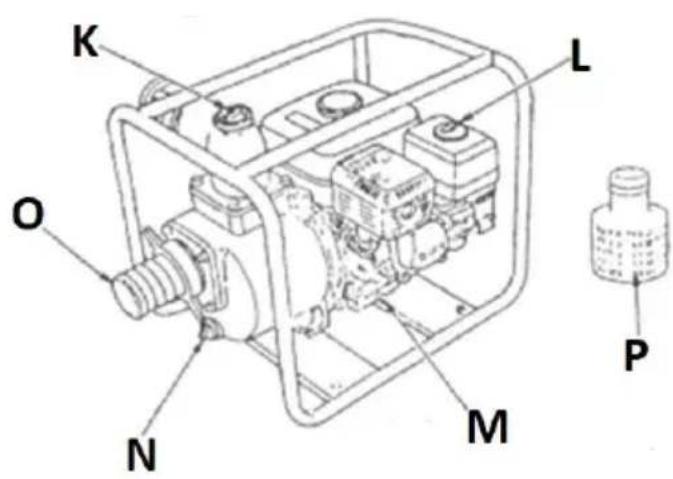
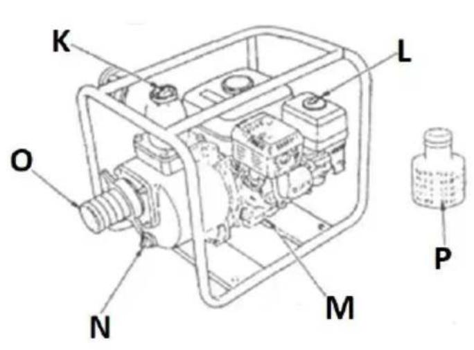
K. Water filler cap
L. Air filter housing
M. Engine oil drain plug
N. Residual water drain plug
O. Water intake nozzle
P. Water filter (suction)
3.2. Preparing for use
APPLIANCE LOCATION
Use the unit only in open spaces or well-ventilated areas. Do not block the air inlet or exhaust of the unit. Keep the unit away from any hot surfaces. Always operate the unit on a level, stable, fireproof and dry surface and out of the reach of children and persons of impaired mental, sensory and intellectual functions. The work area of the unit should provide immediate access to the power switch.
ASSEMBLY OF THE UNIT
The unit is a free-standing unit. Before use, connect hoses with adapters for the water inlet end (O) and outlet end (D).
Place a filter (P) on the end of the water intake hose.
IMPORTANT: Do not operate pump without the water filter.
Secure the hoses at the ends with the included clamps. Secure the water filter at the end of the suction hose in the same way. Hose lengths must not exceed the specified parameters.
natural_image
Technical line drawing of a mechanical assembly with no visible text or symbols
natural_image
Hand-drawn sketch of a cylindrical capacitor with no visible text or symbols
natural_image
Illustration of a mechanical device with hoses and components (no text or symbols)IMPORTANT: the pump has its greatest capacity when placed as close as possible to the intake water tank.
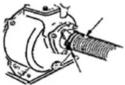
Next, top up the oil in the engine - to do this, unscrew the oil plug and pour engine oil through it until its level reaches the appropriate field on the plug's dipstick - preferably closer to the maximum allowable level.
Check the oil level by screwing/inserting the plug with the dipstick wiped dry into the engine and after a few seconds unscrewing it again and checking to what level the accumulated oil on the dipstick reaches.
IMPORTANT: Always check the engine oil level with the engine off and cold or cooled down.
Do not overfill the engine oil - it can damage the engine! If the oil level exceeds the permissible level, suck out the excess oil through the filler plug.
3.3. Device use
3.3.1 Operation of the unit Before (first) start-up
- Place the unit on a flat, solid surface, not tilting it more than 20^ from the proper vertical position.
- Check the engine oil level (see section 3.2)
- Fill the tank with fuel - to do this unscrew the tank cap and fill the tank taking care not to pour fuel over the maximum level indicator i.e. the level mark on the filter located in the tank filler hole. Place the filler cap by tightening it all the way.
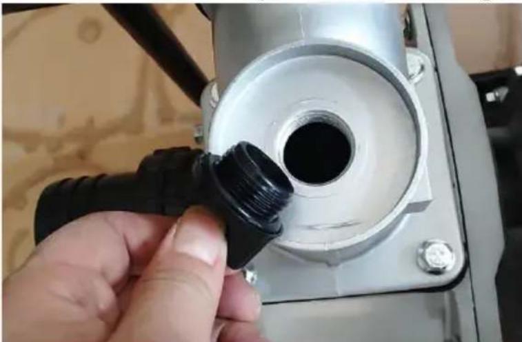
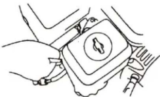
- Fill the pump with (clean) water - to do so, unscrew the water filler cap and fill up with water up to the cap. Screw the water filler cap back on. IMPORTANT: a running pump is cooled by the water flowing through it, therefore it must not be started "dry" - risk of overheating and damage!
natural_image
Close-up of a hand inserting a black plastic plug into a white mechanical component (no text or symbols visible)NOTE: after pumping water, if the pump sucks air, turn it off immediately and pour cool water into the pump through the filler plug to cool it down.
3.3.2 STARTING THE ENGINE:
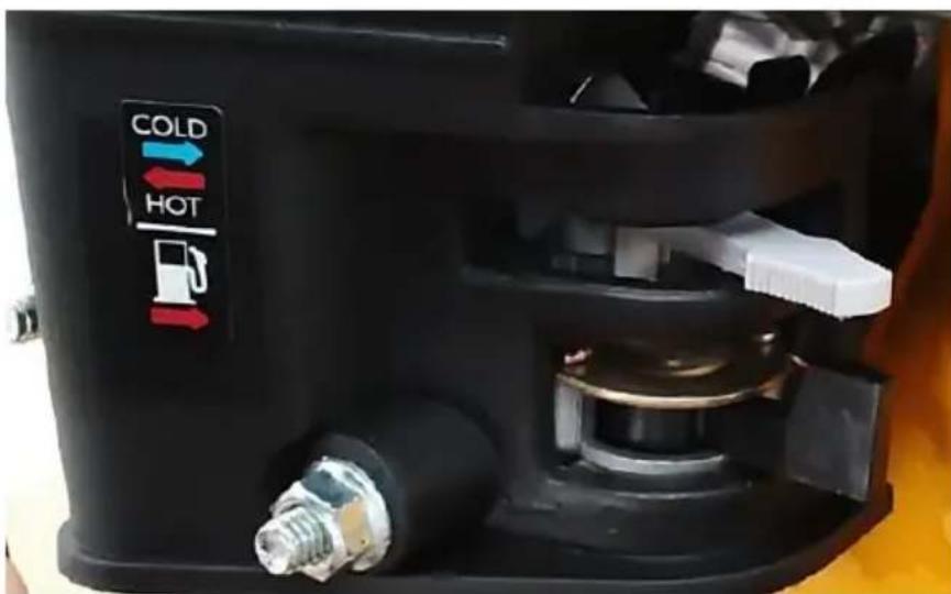
- Open the fuel valve by moving the fuel valve lever to the open position indicated by the arrow (see fuel dispenser pictogram in the above picture).
- (only if the engine is cold or stalls immediately after starting; cold ambient conditions): Turn on the choke, i.e., move the choke valve to the "COLD" position (see suction pictogram in the above image: blue arrow = choke ON).
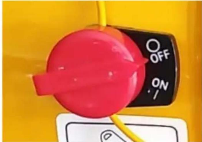
- Move the ignition switch to the "ON" position:
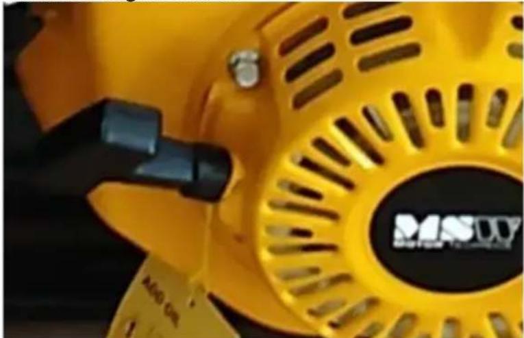
- Grasp the recoil starter handle and slowly pull away from the unit until you feel resistance, then pull with a firm motion, keeping the handle in your hand at all times even as it returns to the starting position. Repeat this motion until the engine starts:
natural_image
Close-up of a yellow industrial fan or pump with black handle and circular vent, no visible text or symbols.- Allow the engine to run with choke for about 1-3 minutes to reach operating temperature.
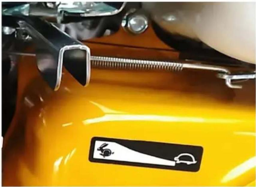
- Then smoothly turn off the choke (set its lever gradually to "HOT" position) and set the desired engine speed with the throttle lever - moving the lever in the direction of the turtle pictogram decreases the speed, and in the direction of the hare pictogram increases it:
3.3.3 Turning the engine off
- Set the throttle lever to the lowest engine speed (pictogram of a turtle).
- Turn the ignition switch to the "OFF" position - the engine will stop.
- In case of further non-use, close the fuel valve by moving its lever to the opposite position to the arrow.
IMPORTANT: in case of emergency shutdown of the pump: just turn the ignition switch to the "OFF" position - the engine will stop immediately. Close the fuel valve.
3.3.4 TRANSPORT AND STORAGE
If the equipment is not to be used again, cool it down completely before transporting.
- Flush the pump with clean water, then drain any remaining water by unscrewing the water drain plug (N).
- Close the fuel valve (I). For transport, it is advisable to empty the fuel tank to prevent any fuel leakage during transport. Transport the unit in a horizontal position – same as set during operation.
If the unit is not used for an extended period of time:
- Cool the unit.
- Flush the pump with clean water and pour off any remaining water by unscrewing the water drain plug (N).
- Turn off fuel valve (to "OFF" position).
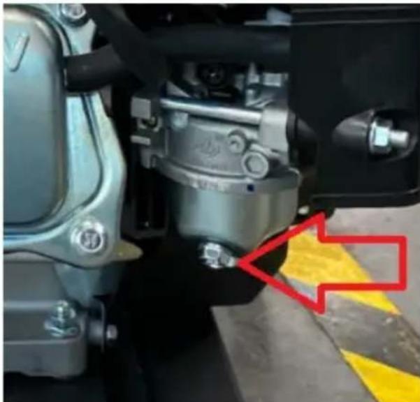
- Empty any residual fuel from the fuel drop tank in the carburetor by unscrewing the bolt on the bottom of the carburetor (see image
below).
natural_image
Close-up of a mechanical assembly with no visible text or symbols- Open the fuel valve and pour the remaining fuel out of the tank.
- Screw the bolt on the bottom of the carburetor drop tank back in.
- Replace the engine oil with fresh one.
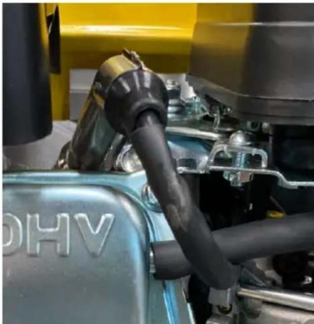
- Remove the spark plug (located under the ignition wire boot - see image below) and pour a little fresh engine oil through its hole in the engine.
- Then grasp the recoil starter handle to turn the engine piston several times to distribute the oil in the cylinder. Reinstall the spark plug in the engine and put on the wire boot.
natural_image
Close-up of a blue automotive engine component with black hoses and yellow background (no visible text or symbols)• Cover the pump to protect it from dust and sunlight.
3.4. Cleaning and maintenance
a) Before cleaning, adjustment, replacement of accessories, and when the unit is not in use, turn off the engine and cool the unit completely.
- Wait until the rotating parts stop.
b) Use only non-corrosive cleaning agents for cleaning the surfaces.
c) Store the unit in a dry and cool place protected from moisture and direct sunlight.
d) Do not spray the unit with a stream of water or immerse it in water.
e) Make sure that no water enters through the ventilation openings in the casing.
f) Clean the ventilation openings with a brush and compressed air.
g) Perform regular inspections of the unit checking technical fitness and any damages.
h) Use a soft cloth for cleaning.
i) Do not use sharp and/or metal objects (e.g. a wire brush or metal spatula) for cleaning, as these may damage the surface of the material from which the unit is made.
j) Change engine oil after the first month or 20 hours of operation. Thereafter, change oil every 300 operating hours or every six months, whichever comes first.
- To change engine oil, it is best done when the oil is warm because it is thinner and flows more easily.
- Before unscrewing the oil filler cap and then the drain plug, first put a container for used oil underneath it.
- After draining the oil, close the drain plug tightly and wipe dry the area around it from the rest of the used oil. You can refill the engine with fresh oil.
CAUTION: the engine oil after work is hot - risk of burns!
k) Inspect the spark plug from time to time for wear and dirt.
- To access the spark plug, remove the ignition cable boot under which the plug is screwed into the engine head.
- Unscrew the spark plug and inspect the tip for dirt and burn marks.
- If it only needs to be cleaned, remove deposits on the electrode, e.g. with a wire brush or fine sandpaper, or rinse it in extraction naphta using a brush. Check the electrode gap before reassembly and adjust if necessary.
- Also check the gap at the electrode when installing a new spark plug.
natural_image
Line drawing of hands holding a device with a circular button (no text or symbols)IMPORTANT: It is advised to remove a spark plug when the engine is cold or has cooled down.
CAUTION: A spark plug that has recently been in service can be hot - risk of burns!
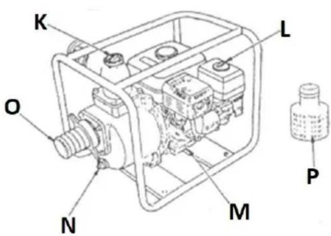
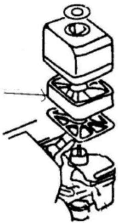
1) Inspect and clean the air filter regularly and replace with a new one if necessary.
- To access the air filter, unscrew the wing nut and remove the housing, among other things (see pictures below).
- The sponge filter element (marked with an arrow on the picture below) is removable and can be rinsed in warm water with detergent or extraction gasoline.
- Completely dry the sponge filter before immersing it in a fresh engine oil and then squeezing out the excessive amount of oil from it.
IMPORTANT: do not operate unit without the air filter!
natural_image
Diagram of a mechanical assembly with layered components and a tool, no visible text or symbols3.5 Troubleshooting
| Problem | Possible cause | Action |
| Engine will not start. | a) Too little fuel in the tank.b) Closed fuel valve.c) Fuel does not reach carburetor.d) Ignition switch in "OFF" position.e) Insufficient oil in engine.f) Worn spark plug. or incorrect electrode gap or current is not reaching the plug. | a) Add fuel to the tank.b) Open the fuel valve.c) Loosen the screw at the bottom of the drop tank in the carburetor to make sure fuel is reaching the carburetor.Check the fuel line from the tank to the carburetor and the fuel pump if applicable.d) Turn the ignition switch to the "ON" position.e) Refill the engine oil.f) Remove the spark plug and check itscondition. If it is OK, put it in the ignition cable pipe, close the fuel valve, put the metal body of the spark plug to the engine case (ground) and pulling the starter jerk check if there is a spark on the electrode? |
| Pump does not pump water | a) No water in pump casing.b) Water filter (suction) blocked.c) Suction hose poorly fitted or damaged (leaking).d) Distance between pump and water source too long. | a) Fill the pump housing with fresh water.b) Clean aspiration filter.c) Check the attachment and condition of the suction hose.d) Move the pump closer to the water tank - the closer the better the performance. |
| The pump has sucked in salt water. | a) The pump is not designed to handle salt water; however, temporary operation with salt water should not harm the pump. | a) In the event of salt water intake, turn off the pump immediately and then rinse the inside thoroughly with running water. The remaining water should be discharged through the drain plug in the pump body. Alternatively, connect the pump to a fresh watersource and run it briefly to flush the inside.The remaining water should be discharged through the drain plug in the pump body. |
DISPOSAL OF USED UNITS.
At the end of its useful life, this product should not be disposed of with normal household waste but should be taken to a collection point for the recycling of electrical and electronic equipment. This is indicated by the symbol on the product, operating instructions or packaging. The materials used in this unit are recyclable according to their marking. You will be making an important contribution to protecting our environment by reusing, recycling or otherwise disposing of used units.
Your local administration will provide you with information about the appropriate disposal point for used units.

natural_image
Technical line drawing of a mechanical component with no visible text or symbols
natural_image
Hand-drawn sketch of a cylindrical capacitor with no visible text or symbols
natural_image
Technical line drawing of a mechanical assembly or tool (no text or symbols visible)natural_image
Close-up of a hand inserting a black plastic plug into a white mechanical component (no text or symbols visible)natural_image
Close-up of a yellow industrial fan or pump component with black adjustment knobs and a 'MISDI' logo (no readable text beyond branding)natural_image
Close-up of a mechanical assembly with visible components and a red arrow pointing to a yellow-black striped safety stripe (no text or symbols)natural_image
Close-up of a blue automotive engine component with black hoses and yellow background (no visible text or symbols)natural_image
Line drawing of hands holding a device with a circular button (no text or symbols)natural_image
Diagram of a mechanical assembly with layered components and a hand holding a tool (no text or symbols)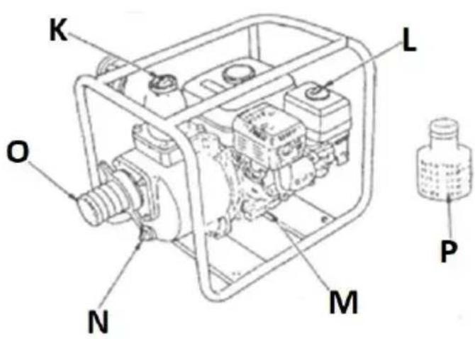
natural_image
Technical line drawing of a mechanical component with no visible text or symbols
natural_image
Hand-drawn sketch of a cylindrical capacitor with a loop and a pin, no text or symbols present
natural_image
Illustration of a mechanical device with hoses and components (no text or symbols)natural_image
Close-up of a hand inserting a black plastic plug into a white mechanical component (no text or symbols visible)natural_image
Close-up of a yellow industrial fan or pump component with visible branding (MSU) and 'RAD 01' text, no readable document content)natural_image
Line drawing of hands holding a device with a circular button and connector (no text or symbols)natural_image
Diagram of a mechanical assembly with layered components and a hand holding a tool (no text or symbols)3.5 Řešení problémů
natural_image
Close-up of a yellow industrial fan or pump with black adjustment knobs and a 'MISUY' logo (no readable text beyond branding)3.3.4 Transport / Stockage
natural_image
Close-up of a mechanical assembly with no visible text or symbolsnatural_image
Close-up of a blue automotive engine component with black hoses and branding (no readable text or symbols)natural_image
Line drawing of hands inserting a device into a car (no text or symbols)natural_image
Diagram of a mechanical assembly with stacked components and a hand holding a tool (no text or symbols)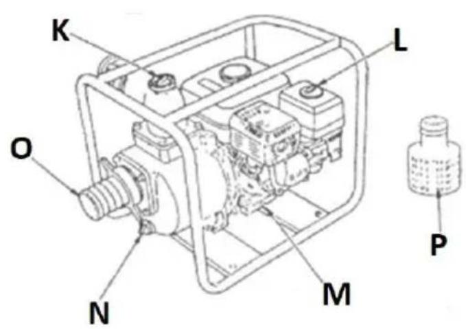
natural_image
Technical line drawing of a mechanical component with a threaded rod inserted (no text or symbols)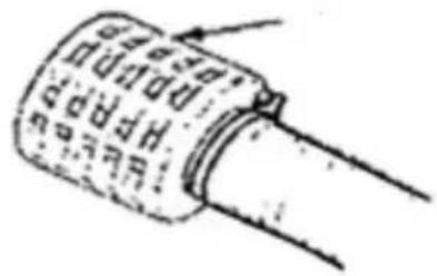
natural_image
Hand-drawn sketch of a cylindrical electronic component with no visible text or symbols
natural_image
Technical line drawing of a mechanical assembly or tool (no visible text or symbols)natural_image
Close-up of a hand inserting a black plastic plug into a white mechanical component (no text or symbols visible)natural_image
Close-up of a yellow industrial machine with visible branding and mounting bracket (no readable text or symbols)natural_image
Close-up of a mechanical assembly with visible components and a red arrow pointing to a yellow-black striped safety stripe (no text or symbols)natural_image
Close-up of a blue automotive engine cylinder with black hoses and attached components, no visible text or symbolsnatural_image
Line drawing of hands inserting a device into a car (no text or symbols)natural_image
Diagram of a mechanical assembly with layered components and a hand holding a tool (no text or symbols)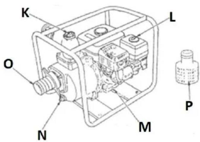
natural_image
Technical line drawing of a mechanical component with no visible text or symbols
natural_image
Hand-drawn sketch of a cylindrical capacitor with a looped shaft (no text or symbols)
natural_image
Illustration of a mechanical device with hoses and components (no text or symbols)natural_image
Close-up of a hand inserting a black plastic plug into a white mechanical component (no text or symbols visible)natural_image
Close-up of a yellow industrial fan or pump with black adjustment knobs and a 'MSUT' logo (no readable text beyond branding)3.3.3 Apagado del motor
natural_image
Close-up of a mechanical assembly with no visible text or symbolsnatural_image
Close-up of a blue automotive engine component with black hoses and branding (no readable text or symbols)natural_image
Line drawing of hands inserting a device into a car (no text or symbols)
natural_image
Technical line drawing of a mechanical component with threaded shaft and mounting base (no text or symbols)

natural_image
Technical line drawing of a mechanical assembly or tool (no text or symbols visible)natural_image
Close-up of a hand inserting a black plastic plug into a white mechanical component (no text or symbols visible)natural_image
Close-up of a yellow industrial fan or pump with black adjustment knobs and a 'MSUY' logo (no readable text beyond branding)natural_image
Close-up of a yellow vehicle's front bumper with a black warning sign and a white gear symbol (no readable text)natural_image
Close-up of a mechanical assembly with visible components and a red arrow pointing to a yellow-black safety stripe (no text or symbols)natural_image
Close-up of a blue automotive engine component with black hoses and valves, no visible text or symbolsnatural_image
Line drawing of hands inserting a device into a car (no text or symbols)natural_image
Diagram of a mechanical assembly with layered components and a tool (no text or symbols)3.5 Hibaelhárítás

APPARATETS PLACERING
natural_image
Technical line drawing of a mechanical assembly with no visible text or symbols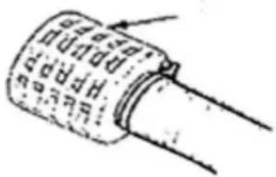
natural_image
Hand-drawn sketch of a cylindrical capacitor with no visible text or symbols
natural_image
Illustration of a mechanical device with hoses and components (no text or symbols)natural_image
Close-up of a hand inserting a black plastic plug into a white mechanical component (no text or symbols visible)natural_image
Close-up of a yellow industrial fan or pump component with visible branding (MSDD) and 'M40 CO' text, no readable document content)3.3.3 Sluk motoren
natural_image
Diagram of a mechanical assembly with layered components and a tool, no visible text or symbols3.5 Problemløsning
natural_image
Technical line drawing of a mechanical component with no visible text or symbols
natural_image
Simple line drawing of a cylindrical capacitor with no text or symbols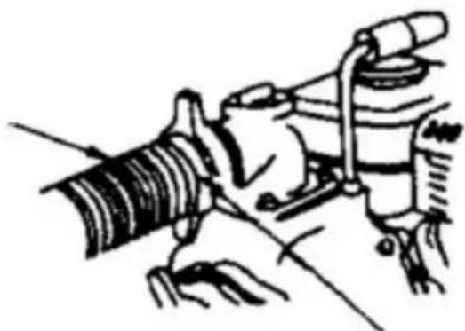
natural_image
Technical line drawing of a mechanical assembly or tool (no visible text or symbols)natural_image
Close-up of a hand inserting a black plastic plug into a white mechanical component (no text or symbols visible)natural_image
Close-up of a yellow industrial fan or pump with black adjustment knobs and a 'MSUY' logo (no readable text beyond branding)natural_image
Close-up of a yellow vehicle's hood with a black warning sign and a white gear symbol (no readable text)natural_image
Close-up of a mechanical assembly with visible components and a red arrow pointing to a yellow-black striped safety stripe (no text or symbols)natural_image
Close-up of a blue automotive engine component with black hoses and branding (no readable text or symbols)natural_image
Line drawing of hands holding a device with a circular button (no text or symbols)natural_image
Diagram of a mechanical assembly with layered components and a hand holding a tool (no text or symbols)3.5 Vianetsintä
PLAATS VAN HET APPARAAT
natural_image
Technical line drawing of a mechanical component with threaded shaft and mounting base (no text or symbols)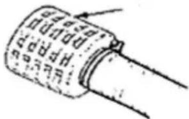
natural_image
Simple line drawing of a cylindrical capacitor with a pin and wire (no text or symbols)
natural_image
Illustration of a mechanical device with hoses and components (no text or symbols)natural_image
Close-up of a hand inserting a black plastic plug into a white mechanical component (no text or symbols visible)natural_image
Close-up of a yellow industrial fan or pump with black adjustment knobs and a 'MISUY' logo (no readable text beyond branding)natural_image
Close-up of a mechanical assembly with no visible text or symbolsnatural_image
Close-up of a blue automotive engine component with black hoses and branding (no readable text or symbols)natural_image
Line drawing of hands inserting a device into a car (no text or symbols)natural_image
Diagram of a mechanical assembly with stacked components and a hand holding a tool (no text or symbols)3.5 Problemen oplossen

A. Gasspak
B. Lyddemper
C. Tankpåfyllingslokk
D. Vannutløpsende
E. Ramme
F. Motorljepåfyllingslokk (med peilepinne)
G. Tenningsläsen
M. Dreneringsplugg for motorolje
natural_image
Technical line drawing of a mechanical component with no visible text or symbols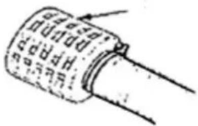
natural_image
Hand-drawn sketch of a cylindrical capacitor with no visible text or symbols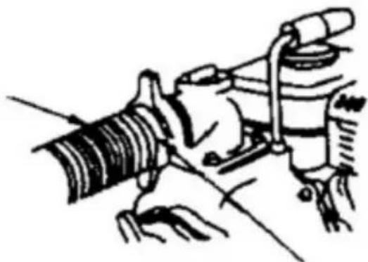
natural_image
Illustration of a mechanical device with hoses and components (no text or symbols)VIKTIG: Pumpen har størst kapasitet når den plasseres så nær inntaksvanntanken som mulig.
natural_image
Close-up of a hand inserting a black plastic plug into a white mechanical component (no text or symbols visible)natural_image
Close-up of a yellow industrial machine with visible branding and mounting bracket (no readable text or symbols)natural_image
Close-up of a mechanical assembly with visible components and a red arrow pointing to a yellow safety stripe (no text or symbols)natural_image
Close-up of a blue automotive engine component with black hoses and yellow background (no visible text or symbols)natural_image
Line drawing of hands inserting a device into a car seat (no text or symbols)VIKTIG: Det anbefales å fjerne en tennplugg när motoren er kald eller avkjølt.
natural_image
Diagram of a mechanical assembly with layered components and hands (no text or symbols)3.5 Feilsøking
OBS! Brandrisk - brandfarliga material!
APPARATENS PLACERING
natural_image
Technical line drawing of a mechanical component with threaded shaft and mounting base (no text or symbols)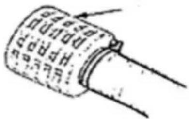
natural_image
Hand-drawn sketch of a cylindrical capacitor with a looped shaft (no text or symbols)
natural_image
Illustration of a mechanical device with hoses and components (no text or symbols)natural_image
Close-up of a hand inserting a black plastic plug into a white mechanical component (no text or symbols visible)natural_image
Close-up of a yellow industrial fan or pump with black adjustment knobs and a 'MSU' logo (no readable text beyond branding)natural_image
Close-up of a mechanical assembly with visible components and a red arrow pointing to a yellow-black safety stripe (no text or symbols)natural_image
Close-up of a blue automotive engine component with black hoses and yellow background (no visible text or symbols)natural_image
Line drawing of hands holding a device with a circular button (no text or symbols)natural_image
Diagram of a mechanical assembly with layered components and a hand holding a tool (no text or symbols)3.5 Felsökning
natural_image
Technical line drawing of a mechanical component with threaded shaft and mounting base (no text or symbols)
natural_image
Hand-drawn sketch of a cylindrical capacitor with no visible text or symbols
natural_image
Illustration of a mechanical device with hoses and components (no text or symbols)natural_image
Close-up of a hand inserting a black plastic plug into a white mechanical component (no text or symbols visible)natural_image
Close-up of a yellow industrial fan or pump component with black adjustment knobs and a 'MISDI' logo (no readable text beyond branding)natural_image
Close-up of a mechanical assembly with no visible text or symbolsnatural_image
Close-up of a blue automotive engine component with black hoses and branding (no readable text or symbols)natural_image
Line drawing of hands inserting a device into a car (no text or symbols)natural_image
Diagram of a mechanical assembly with layered components and a hand holding a tool (no text or symbols)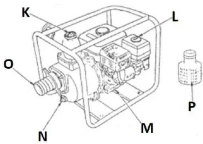
natural_image
Technical line drawing of a mechanical component with threaded shaft and mounting base (no text or symbols)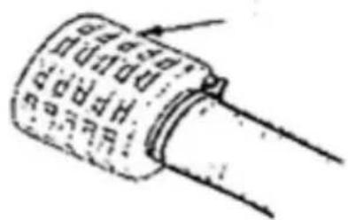

natural_image
Technical line drawing of a mechanical assembly or tool (no visible text or symbols)natural_image
Close-up of a hand inserting a black plastic plug into a white mechanical component (no text or symbols visible)natural_image
Close-up of a yellow industrial fan or pump with black adjustment knobs and a 'MSUY' logo (no readable text beyond branding)3.3.3 Vypnutie motora
natural_image
Close-up of a mechanical assembly with no visible text or symbolsnatural_image
Close-up of a blue automotive engine component with black hoses and branding (no readable text or symbols)natural_image
Line drawing of hands inserting a device into a car (no text or symbols)natural_image
Diagram of a mechanical assembly with stacked components and a hand holding a tool (no text or symbols)For the disposal of the device please consider and act according to the national and local rules and regulations.
CONTACT
expondo Polska sp. z o.o. sp. k.