WOBD-1500L - Plane MSW - Free user manual and instructions
Find the device manual for free WOBD-1500L MSW in PDF.

| Product Type | Thickness Planer |
| Model | MSW-WOBD-1500L |
| Voltage | 230 V~ / 50 Hz |
| Rated Power | 1500 W |
| Protection Class | I |
| Dimensions (L x D x H) | 430 x 915 x 480 mm |
| Weight | 26.5 kg |
| No-load Speed | 9000 rpm |
| Max. Cutting/Planing Thickness | 2.5 mm / 2 mm |
| Guide Angle Adjustment | 90° - 135° |
| Max. Workpiece Width for Planing | 252 mm |
| Min./Max. Workpiece Thickness | 5 mm / 120 mm |
| Main Functions | Planing and thicknessing |
| Dust Extraction System | With adapter for external extraction |
| Overload Protection | Yes |
| On/Off Switch | With safety lock |
| Adjustable Blade Guard | Yes |
| Parallel Guide | Adjustable angle |
| Push Stick and Clamp Included | Yes |
| Maintenance | Regular cleaning, lubrication after 10 h |
| Blade Replacement | In pairs, with adjustment tool |
| Belt Replacement | Possible, remove front cover |
| Max Ambient Temperature | 40 °C |
| Max Relative Humidity | 85 % |
Frequently Asked Questions - WOBD-1500L MSW
User questions about WOBD-1500L MSW
0 question about this device. Answer the ones you know or ask your own.
Ask a new question about this device
Download the instructions for your Plane in PDF format for free! Find your manual WOBD-1500L - MSW and take your electronic device back in hand. On this page are published all the documents necessary for the use of your device. WOBD-1500L by MSW.
USER MANUAL WOBD-1500L MSW
natural_image
Two black plastic electronic components, one rectangular and one tapered, shown without any text or symbols.natural_image
Close-up of a mechanical component with four circular annotations highlighting features (no text or symbols present)natural_image
Mechanical assembly diagram showing a shaft and housing with mounting brackets and a lever, labeled 'A' (no text or symbols beyond label)natural_image
Person using a mechanical press or clamp device on a workbench, no visible text or symbolsnatural_image
Close-up of hands assembling a mechanical component with visible gears and shafts (no text or symbols)This User Manual has been translated for your convenience using machine translation. Reasonable efforts have been made to provide an accurate translation; however, no automated translation is perfect nor is it intended to replace human translators. The official User Manual is the English version. Any discrepancies or differences created in the translation are not binding and have no legal effect for compliance or enforcement purposes. If any questions arise related to the accuracy of the information contained in the User Manual, please refer to the English version of those contents which is the official version.
Technical data
| Parameter description | Parameter value |
| Product name | Planer Thicknesser |
| Model | MSW-WOBD-1500L |
| Supply voltage [V~] / Frequency [Hz] | 230 / 50 |
| Rated power [W]. | 1500 |
| Safety class | I |
| Dimensions [width x depth x height; mm] | 430 x 915 x 480 |
| Weight [kg] | 26.5 |
| Rotation speed without load [rpm] | 9000 |
| Maximum thickness of cutting/planing [mm] | 2.5 / 2 |
| Adjusting the angle of the thicknesser guide [°] | 90-135 |
| Maximum width of a piece of wood for planing [mm] | 252 |
| Minimum/maximum thickness of a piece of wood for planing [mm] | 5/120 |
1. General Description
The manual is intended to assist in safe and reliable use. The product is designed and manufactured strictly according to technical specifications using the latest technology and components and maintaining the highest quality standards.
CAREFULLY READ AND UNDERSTAND THIS MANUAL BEFORE STARTING THE WORK.
To ensure the long and reliable operation of the device, make sure to operate and maintain it properly following the guidelines in this instruction manual. The technical data and specifications in this manual are up-to-date. The manufacturer reserves the right to make changes to improve the quality. Taking the technical progress and the possibility of reducing noise into account, the unit is designed and built in such a way that risks resulting from noise emissions are reduced to the lowest possible level.
Explanation of symbols
 | The product complies with applicable safety standards. |
 | Read the manual before use. |
 | Recyclable product. |
 | CAUTION! or WARNING! or REMEMBER! describing a situation (general warning sign). |
 | Wear ear protection. Exposure to noise may cause hearing loss. |
 | Wear protective goggles. |
 | Use protective gloves (only tightly fitting the hand). |
 | Wear a dusk mask (protecting the respiratory tract). |
 | Wear protective footwear. |
 | Use adjustable guards. |
 | CAUTION! Risk of electric shock! |
 | CAUTION! Warning against loud noise! |
 | CAUTION! Spinning elements! |
 | CAUTION! Some components can become very hot during operation - risk of burns! |
 | Don't touch! |
 | For indoor use only. |
 | CAUTION! Sharp, moving parts of the machine! Danger of injury or severing fingers/limbs. |

CAUTION! The figures in this manual are illustrative only and may vary in some details from the actual appearance of the product.
2. Safety of use

CAUTION! Read all safety warnings and instructions. Failure to follow the warnings and instructions may result in electric shock, fire, and/or serious injury or death.
The term "device" or "product" in the warnings and the description of the instructions refers to:
Planer thicknesser
2.1. Electrical safety
a) The plug of this device must fit into the outlet. Do not modify the plug in any way. Original plugs and matching outlets reduce the risk of electric shock.
b) Avoid touching grounded parts, such as pipes, heaters, ovens, and refrigerators. There is an increased risk of electric shock if your body is grounded and touches the device while exposed to direct rain, wet pavement, or while working in a damp environment. If water enters the device, there is an increased risk of damage to the unit and electric shock.
c) Do not touch the device with wet or damp hands.
d) Do not use the cord in an unintended manner. Never use it to carry the device or to pull the plug out of the socket. Keep the cord away from heat sources, oil, sharp edges, or moving parts. Damaged or tangled cords increase the risk of electric shock.
e) Do not use the unit if the power cord is damaged or shows signs of wear. A damaged power cord should be replaced by a qualified electrician or the manufacturer's service department.
f) To avoid electric shock, do not immerse the cable, plug, or the appliance itself in water or other liquid. Do not use the product on wet surfaces.
g) Do not use the device in rooms with very high humidity / in the immediate vicinity of water tanks!
h) Do not allow the machine to get wet. Risk of electric shock!
i) Before the initial use, please check whether the type of current and mains voltage corresponds to those indicated on the rating plate.
2.2. Safety in the workplace
a) Keep the work area tidy and well-lit. Disorder or poor lighting can lead to accidents. Be foresighted, watch what you are doing, and use common sense when using the unit.
b) Do not use the unit in an explosive area, for example in the presence of flammable liquids, gases, or dust. The unit produces sparks that can ignite dust or fumes.
c) If you find any damage or irregularities in the operation of the product, immediately turn it off and report it to an authorized person.
d) If you have any doubts as to whether the unit is working properly or if it is damaged, contact the manufacturer's service department.
e) Repairs to the device may only be carried out by the manufacturer's service. Do not attempt to repair the product on your own!
f) In case of open flames or fire, use only dry powder or snow (CO2) fire extinguishers to extinguish the live equipment.
g) No children or unauthorized persons are allowed in the work area. Inattention can cause losing control of the unit.
h) Use the product in a well-ventilated area.
i) Dust and debris are generated during product use. Protect bystanders against their harmful effects.
j) Check the condition of the safety stickers regularly. If the stickers are illegible, they must be replaced.
k) Keep these instructions for use for future reference. If the unit is to be passed on to third parties, the operating instructions must also be handed over together with the unit.
I) Keep packaging components and small installation parts out of the reach of children.
m) Keep the device away from children and animals.
n) When using this product together with other devices, also follow the other instructions for use.

Remember! Keep children and other bystanders safe while operating the equipment.
2.3. Personal safety
a) Do not operate this device if you are tired, ill, or under the influence of alcohol, drugs, or medication that could impair your ability to operate the device.
b) The unit may be operated by persons who are physically fit, capable of operating it, and appropriately trained, and who have read this instruction manual and have been trained in occupational safety and health.
c) The machine is not intended to be used by persons (including children) with reduced mental, sensory, or intellectual functions or persons who lack experience and/or knowledge unless they are supervised or have been instructed by a person responsible for their safety on how to operate the machine.
d) Please be attentive and use common sense when operating this equipment. A moment's inattention during operation may result in serious personal injury.
e) Use the personal protective equipment required when working with the device, as specified in point 1. "Explanation of symbols." The use of appropriate, approved personal protective equipment reduces the risk of injury.
f) To prevent accidental start-up, make sure the switch is in the off position before connecting to a power source.
g) Do not overestimate your capabilities. Maintain body balance and equilibrium at all times during operation. This allows for better control of the machine in unexpected situations.
h) Do not wear loose clothing or jewelry. Keep hair, clothing, and gloves away from moving parts. Loose clothing, jewelry, or long hair can be caught in moving parts.
i) If the unit is provided with extraction connections, check that they are correctly connected and fixed. Using dust extraction can reduce dust hazards.
j) Before switching the unit on, remove any regulating tools or keys. Any tools or keys left in the rotating part of the unit may cause injury.
k) The product is not a toy. Children should be watched to ensure that they do not play with the product.
I) Do not place your hands or any objects inside the running device!
2.4. Safe use of the device
a) Do not overload the device. Use tools that are suitable for the application. A correctly selected unit will do a better and safer job for which it was designed.
b) Do not use the device if the "ON / OFF" switch does not work properly (does not turn the device on and off). Units that cannot be controlled by the switch are unsafe, cannot operate, and must be repaired.
c) Disconnect the device from the power supply before adjusting, cleaning, or servicing. This precaution reduces the risk of accidental start-up.
d) Keep unused product out of the reach of children and anyone unfamiliar with the device or this manual. Products are dangerous when used by inexperienced users.
e) Keep the product in good working order. Check before each use for general damage or damage to moving parts (cracks in parts and components or any other condition that may affect the safe operation of the device). If damaged, return the device for repair before use.
f) Keep the product out of the reach of children.
g) Repairs and maintenance should be carried out by qualified personnel using only original spare parts. This will ensure the safety of use.
h) To ensure the designed operational integrity of the device, do not remove factory-installed covers or loosen screws.
i) When transporting or moving the device from storage to the place of use, observe the health and safety rules for manual handling applicable in the country where the device is used.
j) Avoid situations where the unit stops working because it is handling a heavy load. This can cause overheating of the drive elements and consequent damage to the equipment.
k) Do not touch any moving parts or accessories unless the device is unplugged.
I) Do not move, shift, or rotate the device while in operation.
m) Do not leave the device switched on unattended.
n) Clean the device regularly to prevent permanent dirt build-up.
o) The provided value of vibration emission is measured according to the standard measurement methods. The value of vibration emission may change if the unit is used under different environmental conditions.
p) Do not process two workpieces at the same time.
q) Do not touch moving parts or accessories unless the unit has been disconnected from the compressed air supply.
r) If you notice any leakage from the unit or hoses, immediately disconnect the compressed air supply and correct the fault.
s) Do not exceed the recommended supply pressure as this may damage the unit.
t) Do not obstruct the air inlet or outlet.
u) The product is not a toy. Cleaning and maintenance must not be performed by children without adult supervision.
v) Do not tamper with the device to alter its performance or design.
w) Keep the unit away from sources of fire and heat.
x) Do not block the ventilation openings of the unit!
y) CAUTION! Some parts of the unit become very hot during operation - there is a danger of burning!
z) Do not touch the moving cutting elements. Danger of injury or severing fingers/limbs.

CAUTION! Although the product has been designed to be safe and has adequate safeguards and despite the additional safety features provided to the user, there is still a slight risk of accident or injury when handling the product. Caution and common sense are advised when using the product.
3. Instructions for use
The device is designed for wood processing - giving it a certain thickness and smoothness. Thanks to the extraction system, the processing will take place in the least dusty conditions possible.
The user is responsible for any damage resulting from misuse.
3.1. Product overview
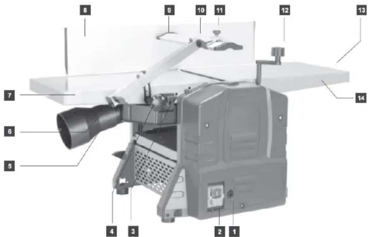
- Overload protection
- Power switch ON/OFF
- Suction manifold locks
- Knife guard locking knob
- Suction manifold with adapter
- Guard fixing screw
- Worktop - receiving end
- Adjustable guide
- Blade guard assembly
- Blade guard adjuster
- Blade guard adjuster screw
- Crank for cutting thickness adjustment
- Planing adjustment knob
- Worktop - feeding end
- Depth of cut indicator
3.2. Preparation for operation
3.2.1 PLACING THE DEVICE
The ambient temperature must not exceed 40^ C and ambient humidity should not exceed 85%. Place the unit in a way that ensures good air circulation. Keep a minimum distance from each wall of the device to ensure freedom of work for the operator and proper distance from bystanders. Keep the unit away from any hot surfaces. Always operate the unit in a well-lit place, on a level, stable, clean, fireproof and dry surface and out of the reach of children and persons of impaired mental, sensory and intellectual functions. Place the unit in such a way that the mains plug can be reached at any time. Ensure that the power supply to the unit corresponds to that specified on the identification plate!
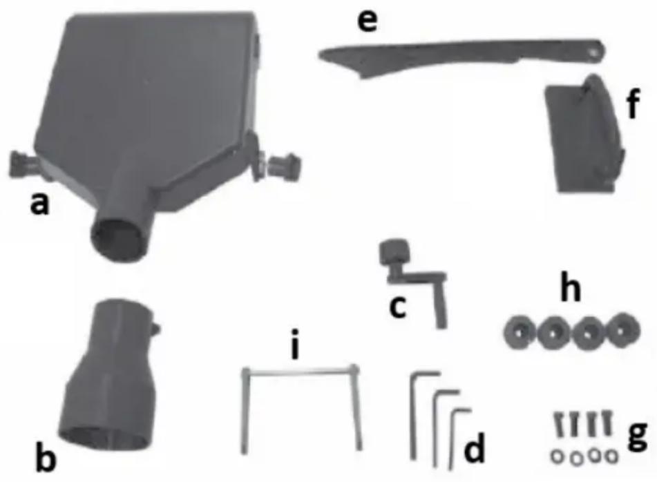
3.2.2 ASSEMBLY OF THE DEVICE

natural_image
Three mechanical components labeled j, k, and k (no text or symbols on parts)a) Suction manifold
b) Suction system adapter
c) Knob for setting the processing thickness
d) Allen keys
e) Pusher
f) Gripper for moving
g) Mounting elements
h) Rubber feet
i) Knife setting tool
j) Guide with adjustable angle
k) Blade guard components
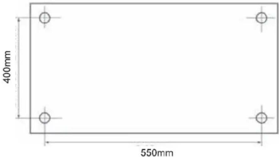
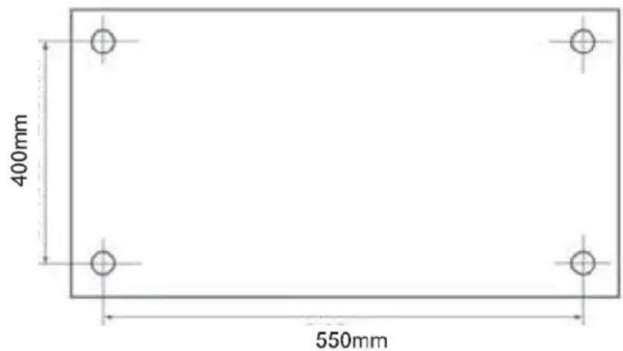
It is recommended to use the device on a workbench. Alternatively, it can be permanently attached to a plywood board with a minimum diameter of 20 mm and a hole spacing of 550 x 400 mm (see image below). Such a plate, together with the attached device, can be temporarily attached to the worktable.
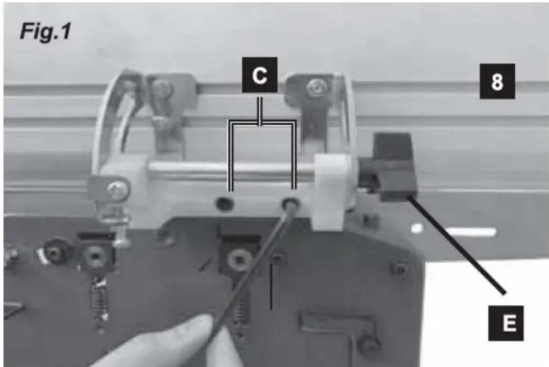
- Mounting the guide
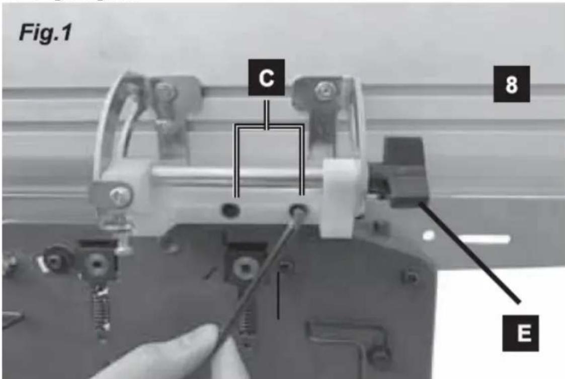
Insert the screws (C) through the holes in the guide (8) and tighten them. If you need to set the angle of the guide, let go of the knob (E) and set the desired angle within the available range, and then tighten the knob again - see the picture above.
- Fixing the worktop adjustment knob
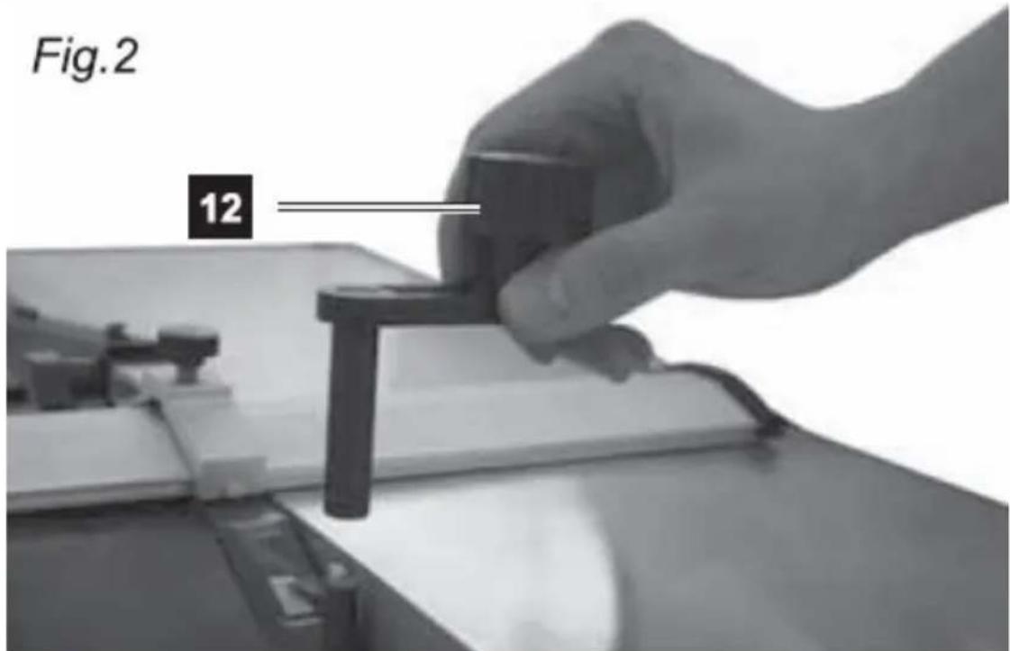
Put the tabletop adjustment knob (12) onto the spindle (see picture above).
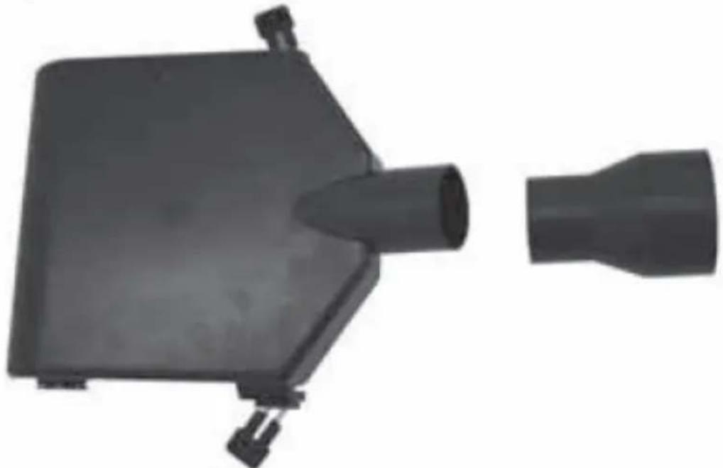
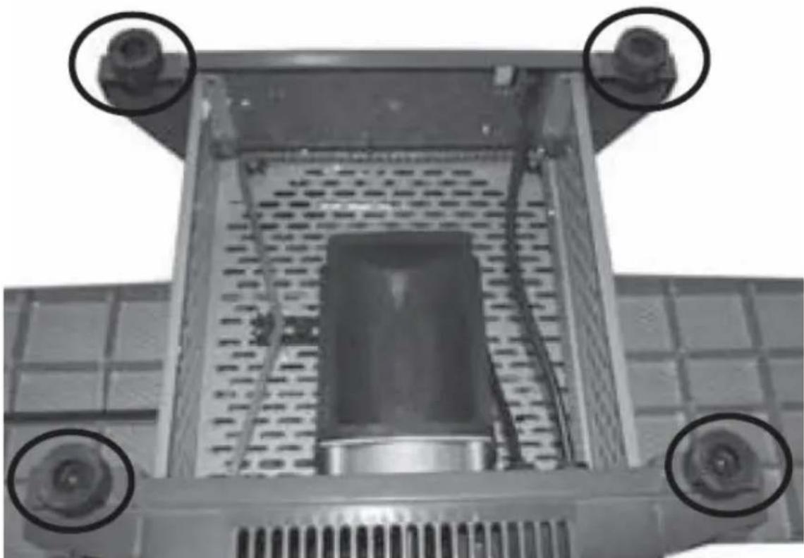
• Installation of the suction system manifold
IMPORTANT: The manifold of the suction system must always be secured with both locks, otherwise the machine will not start.
Fig.3
natural_image
Two black plastic electronic components, one rectangular and one tapered, shown without any text or symbols.For the planning option:
Lower the worktop of the machine as far as possible - by turning the height adjustment knob counterclockwise until it stops. Then pull out both locks (3) of the suction manifold (5) and insert it into the space under the worktop
(see the picture below). Then make sure that both adapter locks (3) are firmly inserted into the holes in the tabletop.
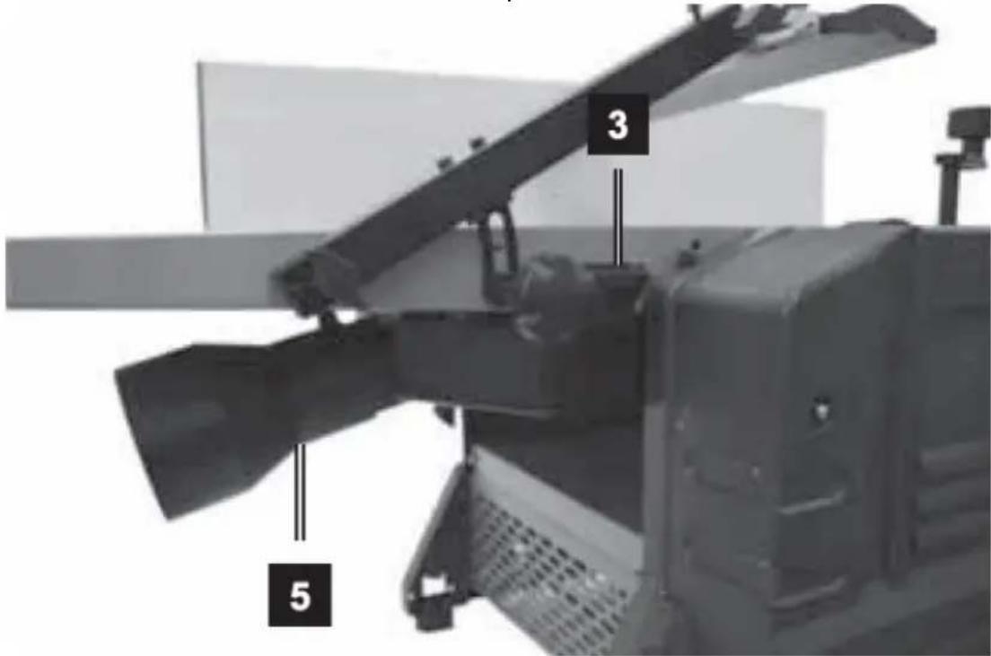
However, in the case of the thicknesser option (see the picture below):
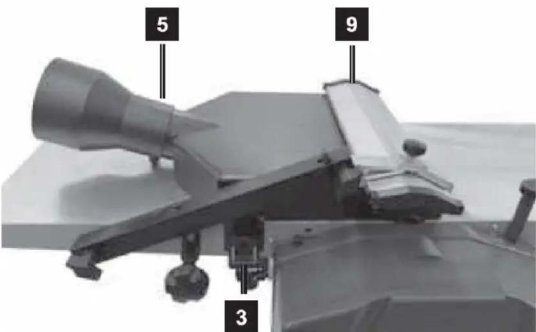
Remove the guide (8) and remove the blade guard (9) from the handle so that the suction system adapter can be installed onto the worktop. Then make sure that both adapter locks (3) are firmly inserted into the holes in the tabletop.
• Installing the blade guard assembly
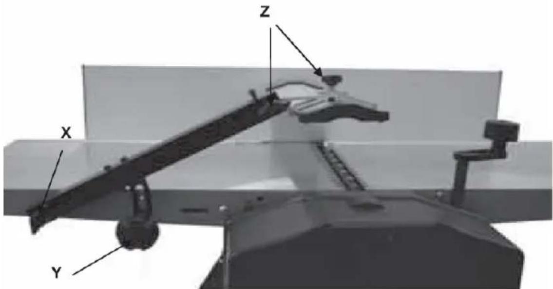
Fasten the thumbscrew (x) in place. Use it to lock the arm securing the blade guard. Tighten the guard arm angle adjustment knob (y). Use the 2 knurled screws (z) to set the angle of the guard.
• Installation of rubber feet.
Attach the feet to the base of the machine using the included Allen screws with washers - tighten securely but gently.
natural_image
Close-up of a mechanical component with four circular annotations highlighting features (no text or symbols present)3.3. Working with the device
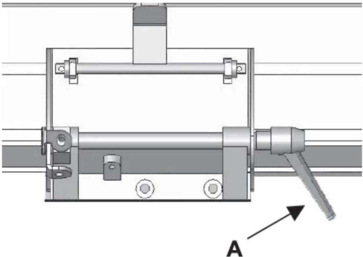
3.3.1 Setting the angle of the guide
Loosen the guide clamping lever (A) and set the desired angle, then tighten the knob again:
natural_image
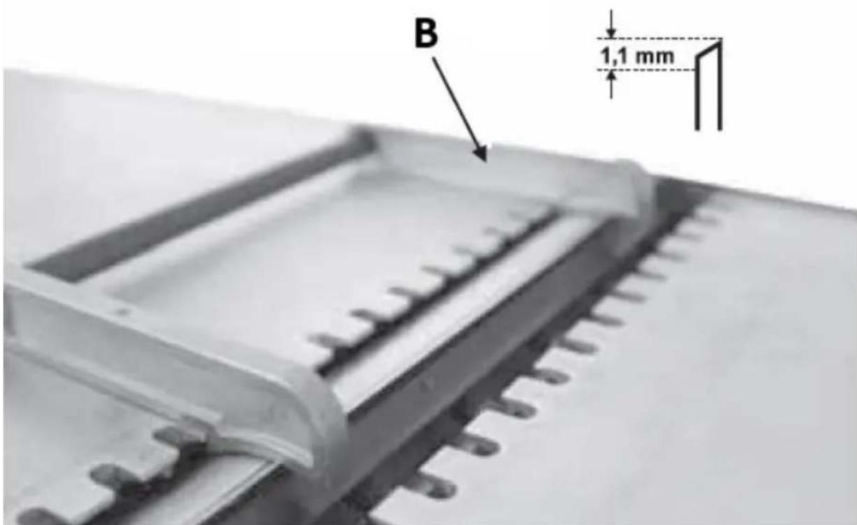
Mechanical assembly diagram showing a frame with mounting brackets and a lever, labeled 'A' with an arrow pointing to it (no text or symbols beyond label)3.3.2 Setting the cutting blade
Position the knife setting tool (B) on the knife block - as shown in the picture below. Make sure the knife touches both edges of the tool. The ideal knife spacing should be 1.1 mm:
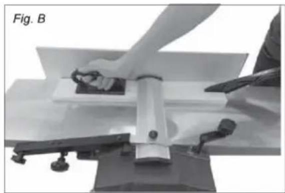
3.3.3 Processing by planing
IMPORTANT: for a better planing/levelling effect, process the piece of wood along its grain structure. Raw wood requires processing of all 4 sides. Use the attached pusher and gripper to move the piece of wood. Never remove wood parts or cuttings from the worktop when the machine is running, especially from around the blade.

natural_image
Person operating a mechanical press or lift device on a workbench, no visible text or symbols- The depth of the plough is regulated by a knob (13) at the receiving worktop. It is recommended to set the depth as not greater than 1 mm and not smaller than 0.5 mm - see indicator (15).
- Make sure that the guide (8) is at the right angle - for regular planing, it will be 90^
- Move aside the blade guard (9) and place the piece on the worktop so that it rests tightly on the guide, with the leading edge at a short distance from the
blade, taking into account that the direction of movement is from right to left as seen from the front of the machine.
- Lower the blade guard so that it lightly touches the piece of wood to be processed and fasten it in this way by tightening its knob.
- Press the "I" button on the ON/OFF switch.
- Pressing down the piece of wood, move it towards the blade along the guide at a steady, slow pace.
- After finishing the treatment, turn off the machine by pressing the "O" button on the ON/OFF switch.
Planning method:
• Determine which wider surface of the wooden piece is the flatter one.
- Pull the wood with the flatter surface through the plane as often as needed until the surface is smooth.
- Hold the side to be processed firmly against the guide (at an angle of 90^ to the edge) and pull it through the plane many times until the side surface is even, smooth.
- In this way, you will obtain 2 processed sides adjacent to each other at an angle of 90^ .
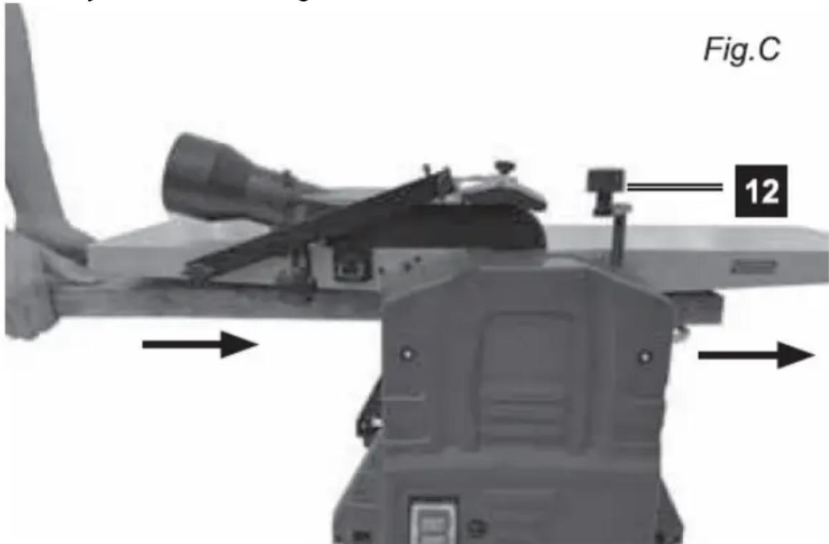
3.3.4 Thickness processing
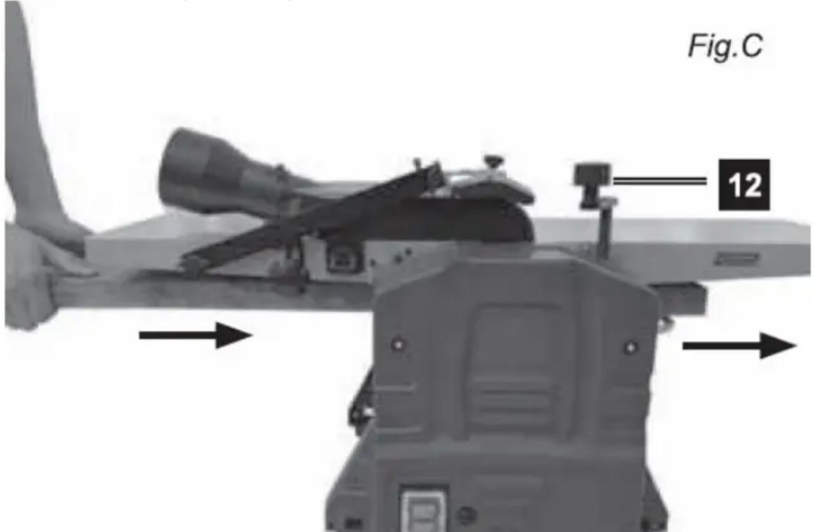
- Lower the worktop with the adjustment knob (12) to the level appropriate to the size of the wooden element that will be below the blade. Processing will run from the left to the right side of the machine.
- Raise the worktop until you feel a slight resistance - felt when the wooden element is barely touching the blade.
- Retract the workpiece and then lift the worktop up - turn it clockwise using the lifting/lowering knob (12) and set the worktop to the correct processing height, taking into account that one cut is 3 mm deep. Do not exceed the value of 2 mm of depth, as this may lead to kickback and/or damage to machine parts or overheating the engine.
- When working with raw or warped pieces of wood, start with a shallow setting - begin at 1 mm or 14 turn of the adjustment knob.
- Longer pieces of wood should always be supported horizontally along the entire workbench in relation to the knife when viewed from the left side of the machine. The roller will automatically feed the workpiece to the blade. For larger (longer) elements, provide them with adequate support at the exit from the machine, i.e. behind the receiving worktop.
Thickness planer method:
- Pull the piece of wood through the thickness plane with the wider, processed side facing downwards in relation to the edge and continue until the thickness of the piece of wood is satisfactory.
- Then, pass the narrower side through the plough of the thickness piece downwards in relation to the edge and continue processing until the thickness is satisfactory.
3.4. Cleaning and maintenance
a) Pull the mains plug and let the unit cool down completely before cleaning, adjusting or replacing accessories and when the unit is not in use.
- Wait until the rotating parts stop.
b) Use only non-corrosive cleaning agents for cleaning the surfaces.
c) Store the unit in a dry and cool place protected from moisture and direct sunlight.
d) Do not spray the unit with a stream of water or immerse it in water.
e) Make sure that no water enters through the ventilation openings in the casing.
f) The vents should be cleaned with a brush and compressed air - especially the ones responsible for cooling the engine.
g) Use a soft cloth and a brush for cleaning.
h) Do not use sharp and/or metal objects (e.g. wire brush or metal spatula) for cleaning as they may damage the surface of the appliance material.
i) Perform regular inspections of the unit checking technical fitness and any damages. After 10 operating hours, it is recommended to lubricate the following components of the machine:
- Bearings of the input/output rollers
• Tensioner bearings and drive belt pulleys - Gears and threaded spindles for adjusting the height of the worktop (with dry grease)
- Worktops and input / output rollers should always be clean and free from sticky coatings (e.g. resin)
j) The cutting head, clamping elements, blade supports and blades must be free of contaminants, especially sticky ones, to ensure their efficiency and proper functioning. These elements should be cleaned with e.g. white spirit, extraction gas or soaked in paraffin.
3.4.1 Removing the blade
Over time and after some working hours, the cutting blade needs to be periodically sharpened or replaced. To do this, you need to:
- Turn off the device and disconnect from the power source
- Set the cutting height to zero, i.e. turn the height adjustment knob to the stop when the height indicator shows "0"
- Remove the guide
- Lift the blade guard
- Rotate the blade shaft so that the 4 Allen screws holding the blade are visible - carefully unscrew them:
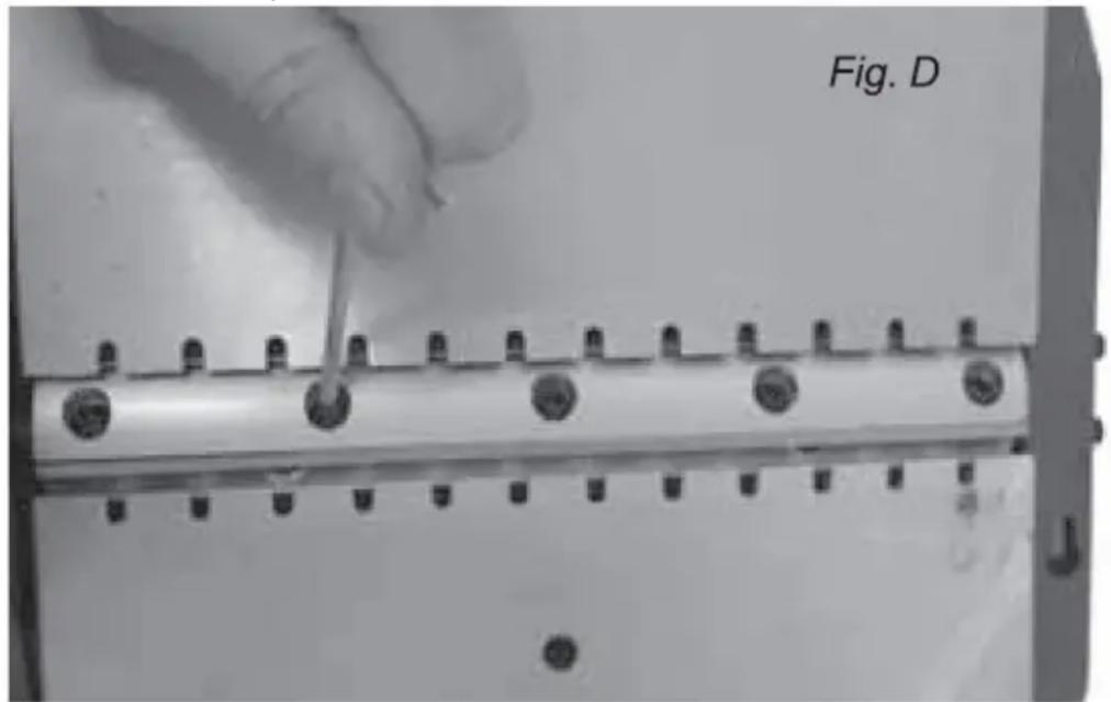
- Rotate the blade shaft by 180 ° and remove the next blade by repeating the above operation.
IMPORTANT: Always sharpen/replace the blades in pairs
- Assemble in the reverse order of removal, taking care that the ends of the blades are in line with the worktop when set to the 12 o'clock position - use the straight edge. Tighten the blade bolts carefully, not too tightly.
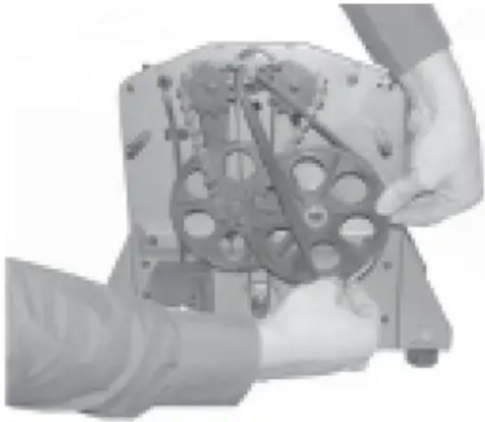
3.4.2 Replacing the drive belt
natural_image
Close-up of hands assembling a mechanical component with gears and shafts (no visible text or symbols)- Remove the 3 screws securing the front cover
- Remove the old belt
- Pass the new belt first over the small pulley and the other end partly through the large pulley
- Manually rotate the large pulley clockwise until the remainder of the drive belt is fully on the pulley
DISPOSAL OF WASTE APPLIANCES
At the end of its useful life, this product should not be disposed of with normal household waste but should be taken to a collection point for the recycling of electrical and electronic equipment. This is indicated by the symbol on the product, operating instructions, or packaging. The materials used in this appliance are recyclable according to their marking. By reusing, recycling, or applying other forms of use of waste machines, you make a significant contribution to the protection of our environment.
Your local administration will provide you with information about the appropriate disposal point for used appliances.
3.4.2 Troubleshooting
| Problem | Possible cause | Action |
| The machine does not start | Blown fuse | Replace the fuse with a good one |
EN
| Interrupted connection with the ON/OFF switch | Check the connection of the ON/OFF switch | |
| Defective ON/OFF switch | Replace the defective switch | |
| The blade guard is not attached | Attach the plastic cover or correct it | |
| The machine only works when the green ON/OFF switch button is pressed and held in this position | Defective power switch | Replace the defective switch |
| The engine of the machine cuts out, the machine operates intermittently | Worn motor carbon brushes | Replace motor carbon brushes |
| The motor runs, but the blade shaft does not rotate | The drive belt is damaged, loose or has come off the pulleys | Reattach the belt or replace it with a new one |
| The motor slows down while the workpiece is being processed | The processing depth is too big | Reduce the cutting depth as recommended |
| Clogged suction system | Remove any debris and make sure the suction system is working properly | |
| Blunt blades | Sharpen or replace the blades (always in pairs) | |
| Strong vibrations Blade | out of balance | Correct the height of the blades in relation to the worktop and fix them evenly |

- Montaż prowadnicy
natural_image
Two black plastic electronic components, one rectangular and one tapered, shown against a white background (no text or symbols visible)natural_image
Top-down view of a mechanical component with four circular annotations highlighting features (no readable text or symbols)natural_image
Mechanical assembly diagram showing a shaft and housing with mounting brackets and a labeled component 'A' (no text or symbols beyond label)natural_image
Person operating a mechanical press or lift device with tools, labeled 'Fig. B' (no visible text on device or background)natural_image
Close-up of hands assembling a mechanical component with visible gears and shafts (no text or symbols)natural_image
Three mechanical components labeled j, k, and k (no text or symbols on parts)- Montáž vodítka

natural_image
Two black plastic electronic components, one rectangular and one tapered, shown against a white background (no text or symbols visible)natural_image
Close-up of a mechanical component with four circular annotations highlighting features (no text or symbols present)natural_image
Mechanical assembly diagram showing a frame with mounting holes and a lever, labeled 'A' (no text or symbols beyond label)natural_image
Person using a flatbed machine on a table, no visible text or symbolsnatural_image
Close-up of a hand using a tool to adjust or install a metal component with multiple bolt holes (no text or symbols visible)natural_image
Close-up of hands assembling a mechanical component with visible gears and shafts (no text or symbols)- Montage du guide

natural_image
Two black plastic electronic components, one rectangular and one tapered, shown against a white background (no text or symbols visible)natural_image
Close-up of a mechanical component with mounting holes and a central square opening (no visible text or symbols)natural_image
Mechanical assembly diagram showing a shaft and housing with mounting holes and a lever, labeled 'A' (no text or symbols beyond label)natural_image
Close-up of a hand using a tool to adjust or install a metal component with multiple bolt holes (no text or symbols visible)natural_image
Close-up of hands assembling a mechanical component with visible gears and shafts (no text or symbols)natural_image
Two black plastic electronic components, one rectangular and one tapered, shown against a white background (no text or symbols visible)natural_image
Close-up of a mechanical component with four circular annotations highlighting features (no text or symbols present)natural_image
Mechanical assembly diagram showing a shaft and housing with mounting holes and a lever, labeled 'A' (no text or symbols beyond label)natural_image
Person operating a mechanical press or lift device with tools, labeled 'Fig. B' (no visible text on device or background)natural_image
Close-up of a hand using a tool to adjust or install a metal component with multiple bolt holes (no text or symbols visible)natural_image
Close-up of hands assembling a mechanical component with visible gears and housing (no text or symbols)natural_image
Two black plastic electronic components, one rectangular and one tapered, shown against a white background (no text or symbols visible)natural_image
Close-up of a mechanical component with four circular annotations highlighting features (no readable text or symbols)natural_image
Mechanical assembly diagram showing a shaft and housing with mounting holes and a lever, labeled 'A' (no text or symbols beyond label)natural_image
Person using a flatbed machine on a workbench, no visible text or symbolsnatural_image
Close-up of hands assembling a mechanical component with visible gears and housing (no text or symbols)natural_image
Two black plastic electronic components, one rectangular and one tapered, shown without any text or symbols.natural_image
Close-up of a mechanical component with four circular annotations highlighting features (no readable text or symbols)natural_image
Mechanical assembly diagram showing a shaft and housing with mounting brackets and a lever, labeled 'A' (no text or symbols beyond label)natural_image
Person operating a mechanical press or lift device on a table, with no visible text or symbols.natural_image
Close-up of a hand using a tool to adjust or install a metal component with multiple pins (no visible text or symbols)HU
natural_image
Three mechanical components labeled j, k, and k (no text or symbols on parts)natural_image
Mechanical assembly diagram showing a frame with mounting holes and a lever, labeled 'A' (no text or symbols beyond label)natural_image
Person operating a mechanical press or lift device with clamps and a flat plate (no visible text or symbols)natural_image
Close-up of hands assembling a mechanical component with visible gears and shafts (no text or symbols)natural_image
Three mechanical components labeled j, k, and k (no text or symbols on parts)natural_image
Close-up of a mechanical component with four circular annotations highlighting features (no text or symbols present)FI
natural_image
Person operating a mechanical press or lift device with clamps and a flat plate (no visible text or symbols)natural_image
Close-up of a hand using a tool to adjust or install a metal component with multiple bolt holes (no text or symbols visible)natural_image
Close-up of hands assembling a mechanical component with gears and shafts (no visible text or symbols)natural_image
Two black plastic electronic components, one rectangular and one tapered, shown against a white background (no text or symbols visible)natural_image
Close-up of a mechanical component with four circular annotations highlighting features (no readable text or symbols)natural_image
Mechanical assembly diagram showing a shaft and housing with mounting brackets and a lever, labeled 'A' (no text or symbols beyond label)natural_image
Close-up of a hand using a tool to adjust or install a metal component with multiple bolt holes (no text or symbols visible)natural_image
Close-up of hands assembling a mechanical component with visible gears and shafts (no text or symbols)- Overbelastningsbeskyttelse
- Strømbryter PÅ/AV
- Sugemanifoldläser
- Knivbeskytter läseknapp
- Sugemanifold med adapter
- Beskyttelsesfesteskrue
- Benkeplate - mottakende ende
- Justerbar guide
- Bladbeskyttelsesenhet
- Bladbeskyttelsesjustering
- Justeringsskrue for bladbeskyttelse
- Sveiv for justering av skjæretykkelse
- Justeringsknapp for høvling
- Benkeplate - mateende
- Kuttdybdeindikator
natural_image
Three mechanical components labeled j, k, and k (no text or symbols on parts)a) Sugemanifold
b) Sugesystemadapter
c) Knott for innstilling av bearbeidingstykkelse
d) unbrakonøkler
e) Pusher
f) Griper for flytting
g) Monteringselementer
h) Gummi føtter
i) Knivinnstillingsverktøy
j) Guide med justerbar vinkel
k) Bladbeskyttelseskomponenter
Det anbefales å bruke enheten på en arbeidsbenk. Alternativt kan den festes permanent til en kryssfinerplate med en minimumsdiameter på 20 mm og en hullavstand på 550 x 400 mm (se bildet under). En slik plate kan sammen med den vedlagte enheten festes midlertidig til arbeidsbordet.
natural_image
Two black plastic electronic components, one rectangular and one tapered, shown without any text or symbols.For planleggingsalternativet:
natural_image
Mechanical assembly diagram showing a frame with mounting holes and a lever, labeled 'A' (no text or symbols beyond label)natural_image
Close-up of hands assembling a mechanical component with visible gears and housing (no text or symbols)• Fjern de 3 skruene som fester frontdekselet
• Fjern det gamle beltet
- Før den nye remmen først over den lille remskiven og den andre enden delvis gjennom den store remskiven
- Roter den store remskiven manuelt med klokken til resten av drivremmen er helt på remskiven


KASSERING AV BRUKTE ENHETER
natural_image
Three mechanical components labeled j, k, and k (no text or symbols on parts)natural_image
Person using a flatbed machine on a table, no visible text or symbols3.3.4 Tjockleksbearbetning
natural_image
Close-up of hands assembling a mechanical component with visible gears and shafts (no text or symbols)- Montando o guia

natural_image
Two black plastic mechanical components, one rectangular and one tapered, shown against a white background (no text or symbols visible)natural_image
Top-down view of a mechanical component with four circular annotations highlighting features (no readable text or symbols)natural_image
Mechanical assembly diagram showing a shaft and housing with mounting brackets and a lever, labeled 'A' (no text or symbols beyond label)natural_image
Person using a flatbed machine on a table, no visible text or symbolsnatural_image
Close-up of hands assembling a mechanical component with visible gears and shafts (no text or symbols)natural_image
Collection of mechanical parts and tools, including a funnel, handle, bracket, and gear assembly (no text or symbols visible)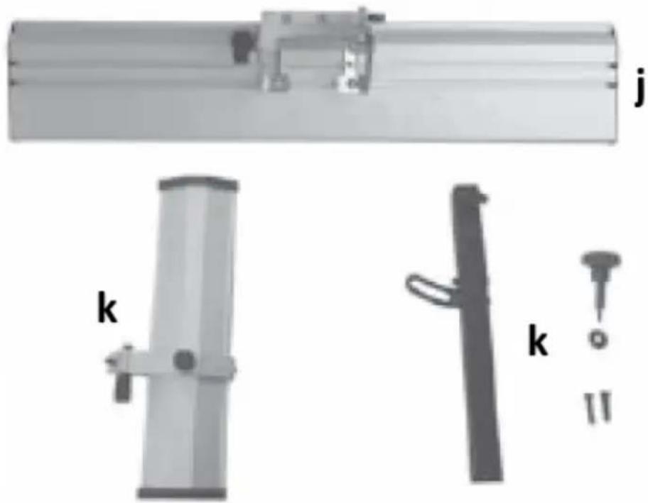
natural_image
Three mechanical components labeled j, k, and k (no text or symbols on parts)a) Sacie potrubie
b) Adaptér sacieho systému
c) Gombík na nastavenie hrúbky spracovania
d) imbusové klúče
e) Tlačidlo
f) Uchopovač na presun
g) Montážne prvky
h) Gumené nožičky
i) Nástroj na nastavenie noža
j) Vodítko s nastavitelným uhlom
k) Komponenty ochrany čepele
- Montáž vodidla

natural_image
Two black plastic electronic components, one rectangular and one tapered, shown against a white background (no text or symbols visible)natural_image
Close-up of a mechanical component with four circular annotations highlighting features (no text or symbols present)natural_image
Mechanical assembly diagram showing a shaft and housing with mounting brackets and a lever, labeled 'A' (no text or symbols beyond label)3.3.2 Nastavenie rezacieho noža
natural_image
Person using a flatbed machine on a workbench, no visible text or symbolsnatural_image
Close-up of a hand using a tool to adjust or install a metal component with multiple bolt holes (no text or symbols visible)natural_image
Close-up of hands assembling a mechanical component with visible gears and housing (no text or symbols)For the disposal of the device please consider and act according to the national and local rules and regulations.
CONTACT
expondo Polska sp. z o.o. sp. k.