HSPR-650 - Paint spray MSW - Free user manual and instructions
Find the device manual for free HSPR-650 MSW in PDF.

| Product type | Airless paint sprayer |
| Brand | MSW |
| Model | HSPR-650 |
| Rated voltage | 230 V / 50 Hz |
| Rated power | 650 W |
| Protection class | I |
| IP protection rating | IP44 |
| Insulation class | H |
| Maximum pressure | 200 bar |
| Flow rate | 1.4 L/min |
| Dimensions (L × W × H) | 365 × 350 × 415 mm |
| Weight | 7.45 kg |
| High-pressure hose length | ~7.5 m |
| Motor speed | 13,000 rpm |
| Included nozzle size | 0.43 mm |
| Supported nozzle size | 0.28 to 0.48 mm |
| Reversible nozzle | Yes, for clearing clogs without disassembly |
| Trigger lock | Yes |
| Tip guard | Yes, reduces injection risk |
| Duty cycle | S2 (intermittent operation) |
| Electrical connection | Grounded plug |
| Usage | Domestic (indoor and outdoor) |
| Maintenance | Clean after each use; inspect gun filter and suction strainer regularly; long-term storage with antifreeze liquid |
| Warranty | See manual or manufacturer |
Frequently Asked Questions - HSPR-650 MSW
User questions about HSPR-650 MSW
0 question about this device. Answer the ones you know or ask your own.
Ask a new question about this device
Download the instructions for your Paint spray in PDF format for free! Find your manual HSPR-650 - MSW and take your electronic device back in hand. On this page are published all the documents necessary for the use of your device. HSPR-650 by MSW.
USER MANUAL HSPR-650 MSW

natural_image
Line drawing of a mechanical pump or cart with wheels and a handle, labeled 'R' (no text or symbols on the diagram itself)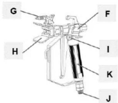

natural_image
Coiled wire with two small rectangular components, labeled 'N' at the end (no other text or symbols)natural_image
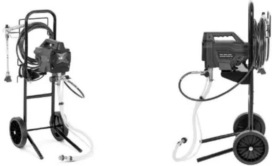
Two industrial water purifier machines with hoses and wheels, shown from different angles (no text or symbols visible)natural_image
Mechanical assembly diagram showing a valve and connecting rod (no text or symbols)natural_image
Mechanical assembly diagram showing a robotic arm and articulated joints (no text or labels)natural_image
Illustration of a robotic device with a lock icon and directional arrow (no text or symbols)natural_image
Two-step diagram showing hand operating a camera setup with tool, no text or symbols presentnatural_image
Technical illustration of a mechanical device with a close-up inset showing a labeled component (no text or symbols present)natural_image
Illustration of a bucket pouring liquid into a container with a lid, alongside a close-up of the interior wall (no text or symbols)natural_image
Close-up of a black electrical switch with a circular button, mounted on a wall (no visible text or symbols)natural_image
Technical illustration of mechanical components with lock and washer symbols (no text or labels)natural_image
Illustration of three cans with paint and a gear mechanism, no text or symbols presentnatural_image
Mechanical assembly diagram showing pipe connection and rotation arrow (no text or symbols)natural_image
Mechanical assembly diagram showing a motor and cable connector with a close-up inset of a labeled component (no text or symbols present)natural_image
Close-up of a black square button with the number '1' and letter 'O' on its side, mounted on a metal panel (no additional text or symbols visible)natural_image
Illustration of three cylindrical containers with embedded electrical components and a star symbol (no text or labels)natural_image
Illustration of three different types of mechanical devices with no visible text or symbolsnatural_image
Illustration of a hand tool and its internal components, showing a disassembly or disassembly process (no text or symbols present)natural_image
Illustration of a camera with a downward arrow indicating compression or disassembly (no text or symbols present)natural_image
Two-step illustration showing hand tool application on tripod and camera setup (no text or symbols)
natural_image
Two-step illustration showing hand tool application on a tripod, with no visible text or symbolsnatural_image
Diagram showing a pipe connection with a directional arrow indicating movement (no text or symbols present)natural_image
Illustration of three cans with paint and a stylized lock, no text or symbols presentnatural_image
Technical illustration of a mechanical device with a cable and connector, showing internal components and a close-up inset (no text or symbols)natural_image
Mechanical assembly diagram showing a valve mechanism with a black curved arrow indicating rotational direction (no text or symbols present)natural_image
Technical line drawing of a spray gun assembly with two components (no text or symbols)natural_image
Illustration of a metallic pipe fitting with a curved handle, partially submerged in liquid (no text or symbols)natural_image
Diagram of a laboratory apparatus with a container and tubing, no visible text or symbolsnatural_image
Illustration of a mechanical device with a lock icon and directional arrow, no text or symbols present.natural_image
3D illustration of a mechanical component with a downward arrow indicating compression or disassembly (no text or symbols)
natural_image
Mechanical component with a curved arrow indicating rotational direction (no text or symbols present)natural_image
Mechanical component diagram showing a lever mechanism with an upward arrow indicator (no text or symbols present)natural_image
Illustration of a hand holding a cylindrical object with a curved handle, no text or symbols presentnatural_image
Mechanical assembly diagram showing a mechanical component with a ball and threaded fitting (no text or symbols)natural_image
Illustration of a mechanical component with three parts, one emitting a ring and the other falling into a sphere (no text or symbols)This User Manual has been translated for your convenience using machine translation. Reasonable efforts have been made to provide an accurate translation; however, no automated translation is perfect nor is it intended to replace human translators. The official User Manual is the English version. Any discrepancies or differences created in the translation are not binding and have no legal effect for compliance or enforcement purposes. If any questions arise related to the accuracy of the information contained in the User Manual, please refer to the English version of those contents which is the official version.
Technical data
| Parameter description | Parameter value | ||
| Product name | Airless sprayer | ||
| Model | MSW-HSPR-650 | MSW-HSPR-650HW | |
| Rated voltage [V~] / Frequency [Hz] | 230/50 | ||
| Rated power [W] | 650 | ||
| Protection class | I | ||
| Protection rating IP | IP44 | ||
| Insulating grade | H | ||
| Duty cycle | S2 | ||
| Dimensions [Width x Depth x Height; mm] | 365 x 350 x 415 400 | x 420 x 1030 | |
| Weight [kg] | 7.45 | 11.8 | |
| Spraying nozzle size [mm] | included 0.43 | ||
| supported 0.28-0.48 | |||
| Flow rate [L/min] | 1.4 | ||
| Max pressure [bar] | 200 | ||
| Spray gun hose length [m] | ~7.5 | ||
| Motor revolution speed [rpm] | 13000 | ||
1. General description
The user manual is designed to assist in the safe and trouble-free use of the device. The product is designed and manufactured in accordance with strict technical guidelines, using state-of-the-art technologies and components. Additionally, it is produced in compliance with the most stringent quality standards.
DO NOT USE THE DEVICE UNLESS YOU HAVE THOROUGHLY READ AND UNDERSTOOD THIS USER MANUAL.
To increase the product life of the device and to ensure trouble-free operation, use it in accordance with this user manual and regularly perform maintenance tasks. The technical data and specifications in this user manual are up to date. The manufacturer reserves the right to make changes associated with quality improvement. The device is designed to reduce noise emission risks to a minimum, taking into account technological progress and noise reduction opportunities.
Legend
| CE | The product satisfies the relevant safety standards. |
 | Read instructions before use. |
 | The product must be recycled. |
 | WARNING! or CAUTION! or REMEMBER! Applicable to the given situation.(general warning sign) |
 | Wear protective goggles. |
 | Wear protective gloves. |
 | Use respiratory tract protection. |
 | Wear protective clothing. |
EN
 | ATTENTION! Electric shock warning! |
 | ATTENTION! Fire hazard - flammable materials! |
 | WARNING! Toxic substances, danger of poisoning! |
PLEASE NOTE! Drawings in this manual are for illustration purposes only and in some details may differ from the actual product.
2. Usage safety
ATTENTION! Read all safety warnings and all instructions. Failure to follow the warnings and instructions may result in electric shock, fire and/or serious injury or even death.
The terms "device" or "product" are used in the warnings and instructions to refer to the:
Airless sprayer.
2.1. Electrical safety
a) The plug must fit the socket. Do not modify the plug in any way. Using original plugs and matching sockets reduces the risk of electric shock.
b) Avoid touching earthed elements such as pipes, heaters, boilers and refrigerators. There is an increased risk of electric shock if the earthed device is exposed to rain, comes into direct contact with a wet surface or is operating in a damp environment. Water getting into the device increases the risk of damage to the device and of electric shock.
c) Use the cable only for its designated use. Never use it to carry the device or to pull the plug out of a socket. Keep the cable away from heat sources, oil, sharp edges or moving parts. Damaged or tangled cables increase the risk of electric shock.
d) If working with the device outdoors, make sure to use an extension cord suitable for outdoor use. Using an extension cord suitable for outdoor use reduces the risk of electric shock.
e) Do not use the device if the power cord is damaged or shows obvious signs of wear. A damaged power cord should be replaced by a qualified electrician or the manufacturer's service center.
f) ATTENTION! DANGER TO LIFE! While cleaning, never immerse the device in water or other liquids.
g) Do not use in very humid environments or in the direct vicinity of water tanks.
h) Before the first use, please check whether the main voltage type and current comply with the indicated data on the type plate.
2.2. Safety in the workplace
a) Make sure the workplace is clean and well lit. A messy or poorly lit workplace may lead to accidents. Try to think ahead, observe what is going on and use common sense when working with the device.
b) Do not use the device in a potentially explosive environment, for example in the presence of flammable liquids, gases or dust. The device generates sparks which may ignite dust or fumes.
c) If you discover damage or irregular operation, immediately switch the device off and report it to a supervisor without delay.
d) If there are any doubts as to the correct operation of the device, contact the manufacturer's support service.
e) Only the manufacturer's service point may repair the device. Do not attempt any repairs independently!
f) In case of fire, use a powder or carbon dioxide (CO2) fire extinguisher (one intended for use on live electrical devices) to put it out.
g) Children or unauthorised persons are forbidden to enter a work station. A distraction may result in loss of control over the device.
h) Use the device in a well-ventilated space.
i) The device produces dust and debris during operation. It is important to protect bystanders from their harmful effects.
j) Only connect and disconnect the pressure line when the air valve is closed.
k) Do not point the pressure line towards yourself or towards other people or animals.
I) When starting the device, increase the air supply to the device gradually in order to ensure that it is functioning properly. If you notice any abnormal operation of the device, disconnect it immediately from the compressed air and contact the manufacturer's service point.
m) Regularly inspect the condition of the safety labels. If the labels are illegible, they must be replaced.
n) Please keep this manual available for future reference. If this device is passed on to a third party, the manual must be passed on with it.
o) Keep packaging elements and small assembly parts in a place not available to children.
p) Keep the device away from children and animals.
q) If this device is used together with another equipment, the remaining instructions for use shall also be followed.

Remember! When using the device, protect children and other bystanders.
2.3. Personal safety
a) Do not use the device when tired, ill or under the influence of alcohol, narcotics or medication which can significantly impair the ability to operate the device.
b) The device can be handled only by physically fit persons who are capable of handling it, properly trained, familiar with this manual and trained within the scope of occupational health and safety.
c) When working with the device, use common sense and stay alert. Temporary loss of concentration while using the device may lead to serious injuries.
d) Use personal protective equipment as required for working with the device, specified in section 1 "Legend". The use of correct and approved personal protective equipment reduces the risk of injury.
e) To prevent the device from accidentally switching on, make sure the switch is on the OFF position before connecting to a power source.
f) Do not overestimate your abilities. When using the device, keep your balance and remain stable at all times. This will ensure better control over the device in unexpected situations.
g) Compressed air may cause serious injury.
h) Use eye, ear and respiratory protection.
i) The device is not a toy. Children must be supervised to ensure that they do not play with the device.
j) It is prohibited to point the gun at yourself, other people or animals.
2.4. Safe device use
a) Do not overload the device. Use the appropriate tools for the given task. A correctly-selected device will perform the task for which it was designed better and in a safer manner.
b) Do not use the device if the "ON/OFF" switch does not function properly (does not switch the device on and off). Devices which cannot be switched on and off using the ON/OFF switch are hazardous, should not be operated and must be repaired.
c) Disconnect the device from the power supply before commencement of adjustment, cleaning and maintenance. Such a preventive measure reduces the risk of accidental activation.
d) When not in use, store in a safe place, away from children and people not familiar with the device who have not read the user manual. The device may pose a hazard in the hands of inexperienced users.
e) Keep the device in perfect technical condition. Before each use check for general damage, especially check moving components for cracked parts or elements, and for any other conditions which may impact the safe operation of the device. If damage is discovered, hand over the device for repair before use.
f) Keep the device out of the reach of children.
g) Device repair or maintenance should be carried out by qualified persons, only using original spare parts. This will ensure safe use.
h) To ensure the operational integrity of the device, do not remove factory-fitted guards and do not loosen any screws.
i) When transporting and handling the device between the warehouse and the destination, observe the occupational health and safety principles for manual transport operations which apply in the country where the device will be used.
j) Avoid situations where the device stops working during use due to excessive loading. This may result in overheating of the drive elements and damage to the device.
k) Do not touch articulated parts or accessories unless the device has been disconnected from the power source.
1) Do not move, adjust or rotate the device in the course of work.
m) Do not leave this appliance unattended while it is in use.
n) Clean the device regularly to prevent stubborn grime from accumulating.
o) The specified vibrations emission was measured using standard measurement methods. Vibrations emissions may change if the device is used in different surroundings.
p) Before each use ensure the nozzle is correctly installed in the device and that the hose is correctly attached and undamaged.
q) Do not carry or hang the device by the pressure line.
r) Do not touch any moving parts or accessories unless the device has been disconnected from the compressed air supply.
s) If you notice a leak from the device or hoses, immediately disconnect the compressed air supply and resolve the defects.
t) Do not run the device when empty.
u) It is forbidden to interfere with the structure of the device in order to change its parameters or construction.
v) Keep the device away from sources of fire and heat.
w) Do not cover the ventilation openings!
x) NOTE: During operation, some elements of the device become very hot – scalding hazard!
y) Do not direct the stream towards sources of air blowing/circulation.

ATTENTION! Despite the safe design of the device and its protective features, and despite the use of additional elements protecting the operator, there is still a slight risk of accident or injury when using the device. Stay alert and use common sense when using the device.
3. Use guidelines
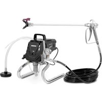
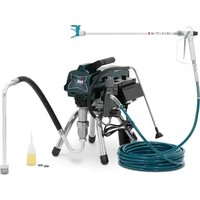
The product is designed to spray paint on large surfaces or elements on the inside or outside and is intended to facilitate and speed up painting works e.g. in construction repair and finishing works.
CAUTION: The unit is not suitable for use with structural paints, primers or asphalt sealers as with fluids that react with aluminium parts of the product (e.g. chlorine).
The product is intended for home use only!
The user is liable for any damage resulting from unintended use of the device.
3.1. Device description
MSW-HSPR-650 shown (MSW-HSPR-650HW similar)
A. Prime/spray valve
B. Pressure control knob
C. ON/OFF-switch
D. Suction tube
E. Drain tube
F. Spraying gun
G. Reversible spraying tip
H. Tip guard
I. Gun trigger lock
J. Gun fluid inlet fitting
K. Gun fluid filter (inside handle)
L. Pump
M. Pump fluid outlet fitting
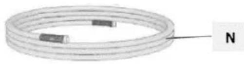
N. High pressure hose
O. Suction filter
P. Power cord
Q. Suction tube drip cup
R. Cart (MSW-HSPR-650HW only)
3.2. Preparing for use
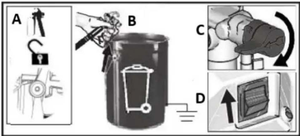
APPLIANCE LOCATION
The ambient temperature must not exceed 40^ C and the relative humidity should not exceed 85%. Only use the device in well-ventilated areas. Do not obstruct the air outlet of the device. Keep the device away from any hot surfaces. The device should always be used when positioned on an even, stable, clean, fireproof and dry surface, and be out of the reach of children and persons with limited mental and sensory functions. The valve/switch that disables the compressed air supply should be immediately accessible from the area where the device is being used. Position the device such that you always have access to the power plug. The power cord connected to the appliance must be properly grounded and correspond to the technical details on the product label.
3.2.1 ASSEMBLING THE APPLIANCE
a) In MSW-HSPR-650HW assemble the cart with the machine first (as shown on the pictures below):
natural_image
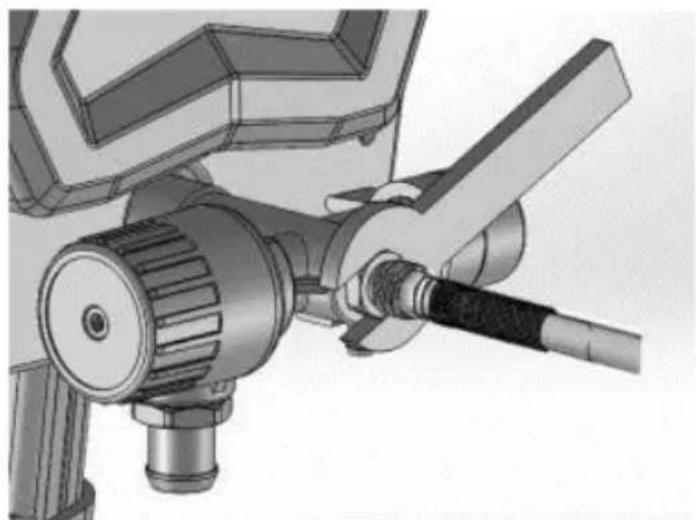
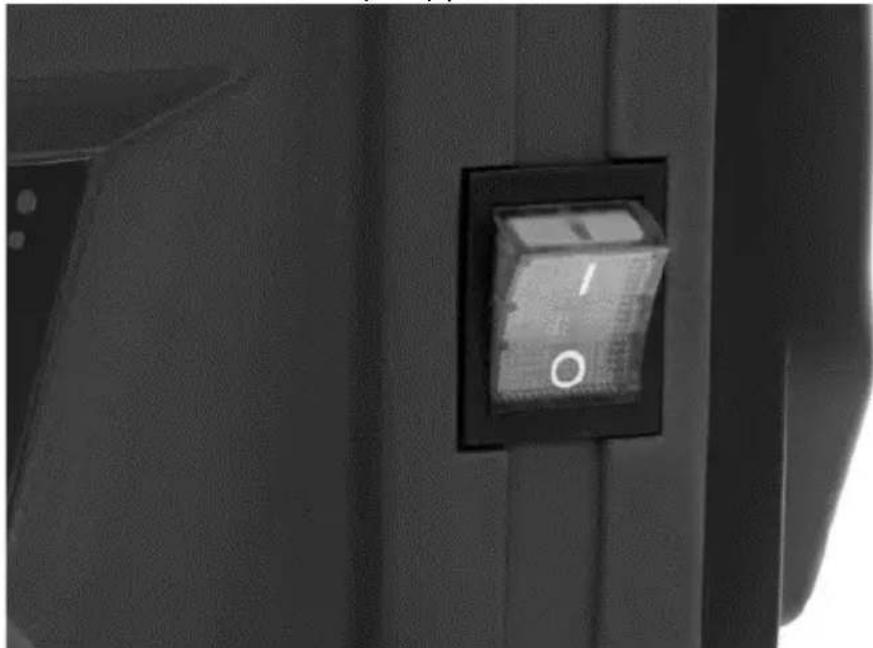
Two industrial pressure sprayer machines with hoses and wheels, shown from different angles (no text or symbols visible)b) Connect airless hose to fluid outlet. Use wrench to tighten them together securely:
natural_image
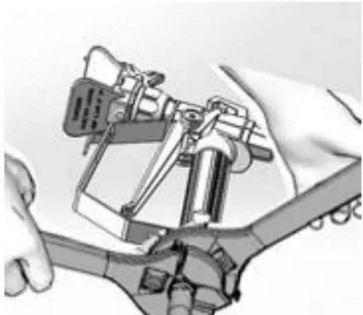
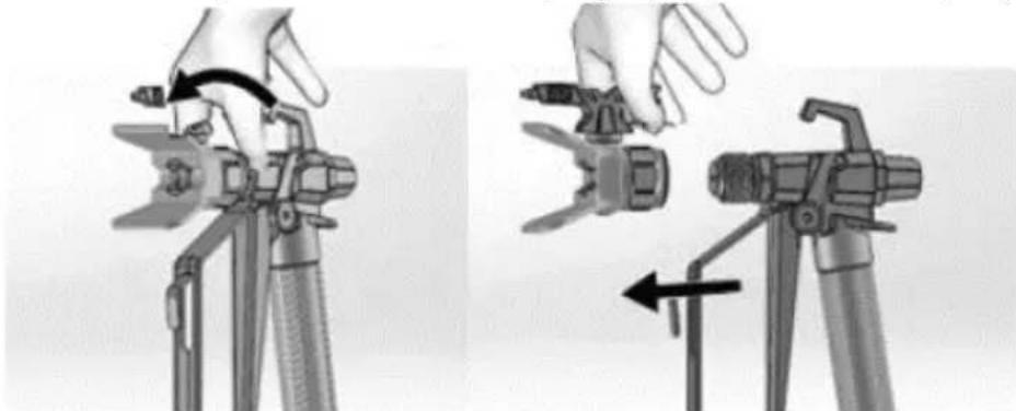
Mechanical assembly diagram showing a valve and connecting rod (no text or symbols)c) Connect the other end of the hose to the spraying gun.
d) Use two wrenches to tighten securely. If hose is already connected, make sure the connections are tight:
natural_image
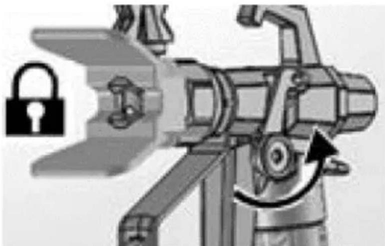
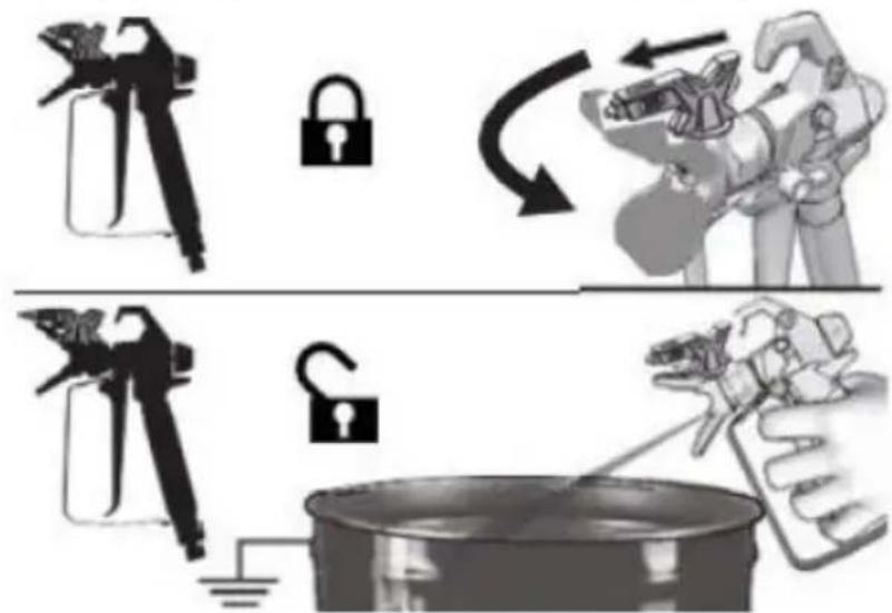
Illustration of a robotic arm with articulated joints and a sensor device (no text or symbols visible)e) Engage trigger lock:
natural_image
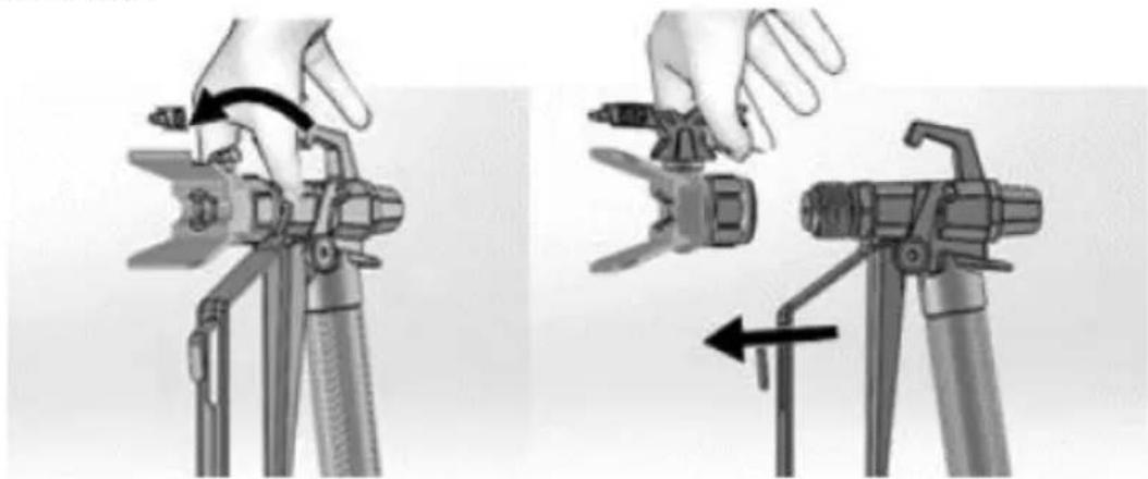
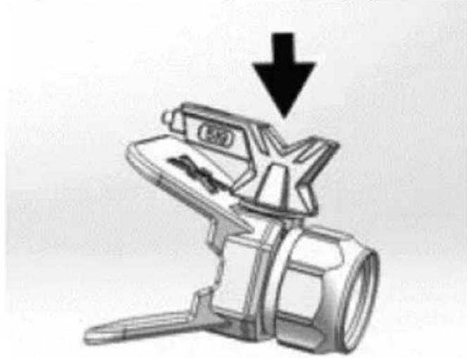
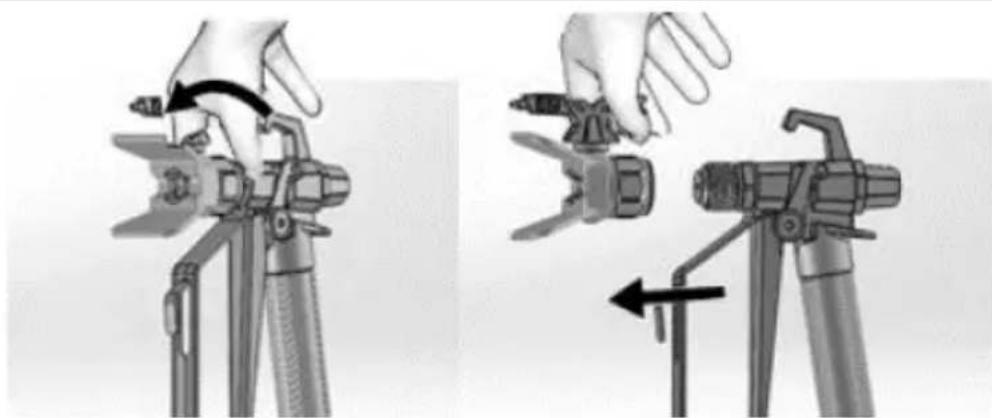
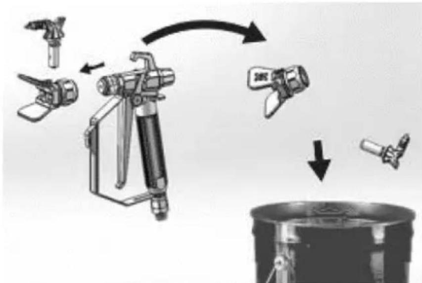
Illustration of a robotic device with a lock icon and directional arrow (no text or symbols)f) Remove the tip guard. Be careful as tip seal may fall out when tip guard is removed:
natural_image
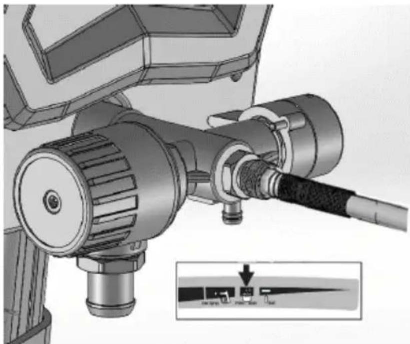
Two-step diagram showing hand operating a camera setup with tool, no text or symbols presentg) Turn the pressure control knob all the way left (counter-clockwise) to the lowest setting:
natural_image
Technical illustration of a mechanical device with attached tubing and a close-up inset showing a control panel (no text or symbols present)h) After long term storage, check the inlet strainer for clogs and debris.
3.3. Device use
3.3.1 Device parts description (see the picture with description)
| Ref. part | Name Function | |
| A | Prime/spray valve | • In PRIME position directs fluid to drain tube.• In SPRAY position directs pressurized fluid topaint hose.• Automatically relieves |
| B | Pressure control knob | Increases (clockwise) and decreases (counter-clockwise) fluid pressure in pump, hose and spray gun. To select function, align symbol on pressure control knob with setting indicator. |
| C | ON/OFF-switch | Turns sprayer on or off. |
| D | Suction tube | Draws fluid from the paint pail into pump. |
| E | Drain tube | Drains fluid in the system during priming and pressure relief. |
| F | Airless spray gun | Dispenses fluid. |
| G | Reversible spray tip | • Atomizes fluid being sprayed, forms spray pattern and controls fluid flow according to hole size.• Reverse position unclogs plugged tips without the need to disassembly. |
| H | Tip guard | Reduces risk of fluid injection injury. |
| I | Gun trigger lock | Prevents accidental triggering of spray gun. |
| J | Gun fluid inlet fitting | Threaded connection for paint hose. |
| K | Gun fluid filter | Filters fluid entering spray gun to reduce tip clogs. |
| L | Pump | Pumps and pressurizes fluid and delivers it to paint hose. |
| M | Pump fluid outlet fitting | Threaded connection for airless hose. |
| N | Airless hose | Transports high-pressure fluid from the pump to the spray gun. |
| O | Suction filter | Prevents debris from entering the pump. |
| P | Power cord | Plugs into power source. |
| Q | Suction tube drip cup | Holds the suction tube during transport to catch drips. |
3.3.2 Straining the paint
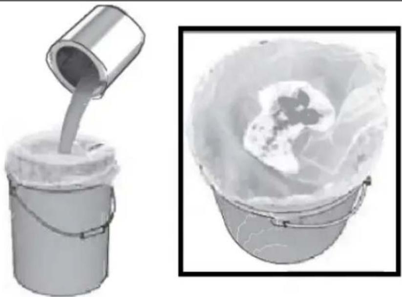
IMPORTANT: Previously opened paint may contain dried paint elements or other debris. To avoid priming problems and spray tip clogs it is recommended to strain the paint before using. Stretch a paint strainer over a clean pail and pour the paint through the strainer to capture any dried paint and debris before spraying:
natural_image
Illustration of a bucket pouring liquid into a container with a lid, alongside a close-up of the interior portion of a bucket filled with ice (no text or symbols)3.3.3 Pressure relief
IMPORTANT: each pneumatic equipment stays pressurized until the pressure is manually relieved. This procedure helps prevent serious injury from pressurized fluid, such as skin injection or splash fluid.
a) Put the ON/OFF-switch to the off ("O") position:
natural_image
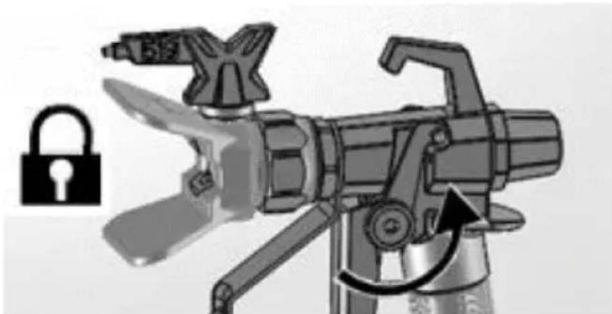
Close-up of a black electrical switch with a circular indicator light on the side panel (no text or symbols visible)b) Engage the trigger lock. It is recommended to engage it always when the machine is stopped, to prevent the gun from being triggered accidentally:

natural_image
Technical illustration of mechanical components with lock and washer symbols (no text or labels)c) Set the pressure control knob to the lowest setting:
natural_image
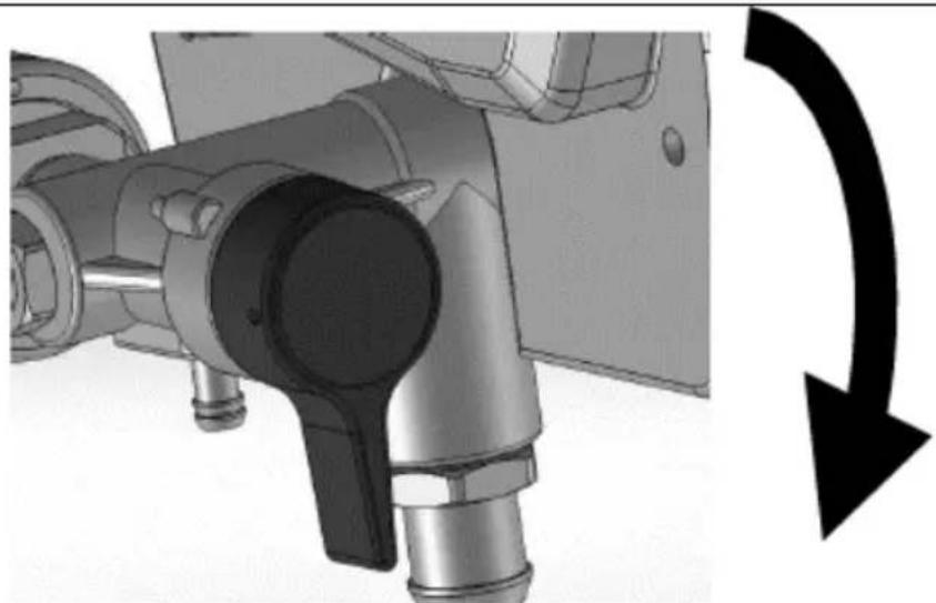
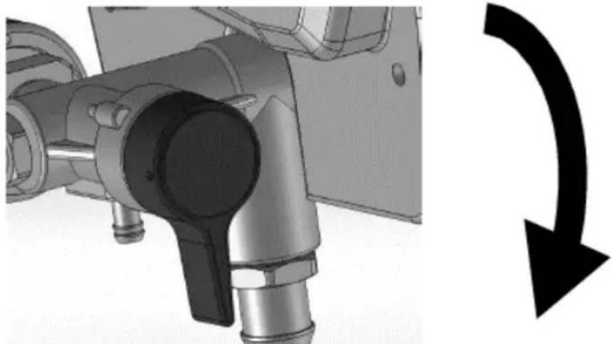
Mechanical device with attached cable and mechanical components, showing a close-up inset of a control panel (no text or symbols visible)d) Put drain tube into a waste pail and turn Prime/Spray valve in PRIME position (drain) to relieve pressure:
natural_image
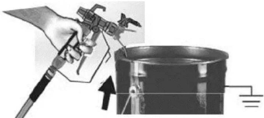
Mechanical assembly diagram showing pipe connection and directional arrow (no text or symbols)e) Hold the gun firmly inside a pail and disengage the trigger lock and pull the trigger to relieve pressure:
natural_image
Illustration of a hand using a tool to lift a cylindrical component, with an upward arrow indicating motion (no text or symbols)f) Engage the trigger lock.
g) If you suspect that the spray tip or hose is clogged or that pressure has not been fully relieved, than:
- Very slowly loosen the tip guard retaining nut or the hose end coupling to relieve pressure gradually.
- Loosen the nut or coupling completely.
- Clear airless hose or spray tip obstruction.
3.3.3 Flush storage fluid
CAUTION: this machine arrives from the factory with a small amount of test material in the system. It is important that you flush this material from the system before using it for the first time. See the chapter “Cleaning fluid compatibility” and “Static grounding (oil-based materials).”
a) Perform pressure relief procedure (described previously).
b) Make sure the ON/OFF-switch is in off ("O").
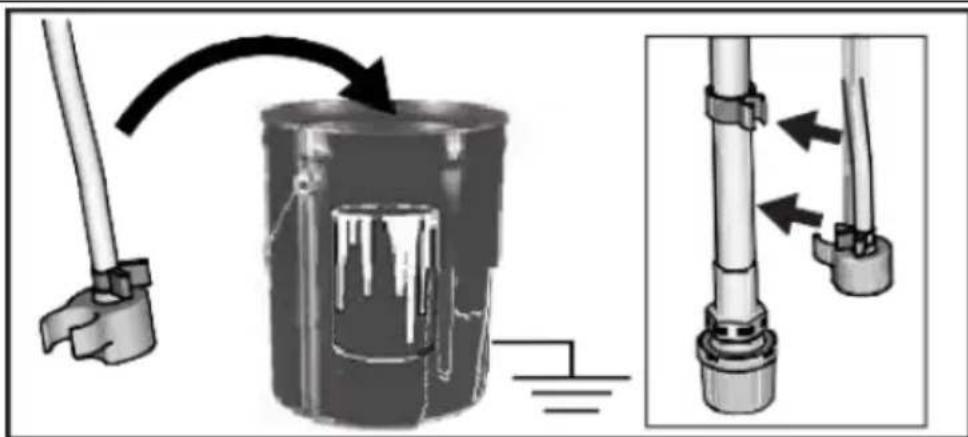
c) Separate the drain tube (smaller) from suction tube (larger).
d) Place the drain tube in a waste pail.
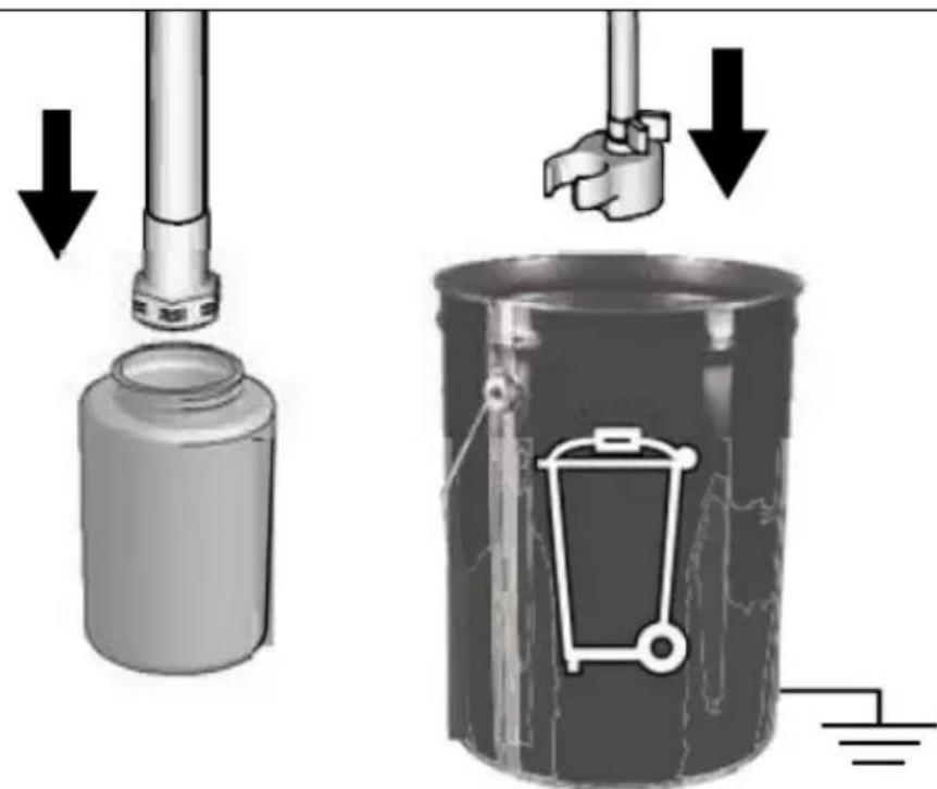
e) Submerge the suction tube in a pail partially filled with water or flushing fluid. If spraying oil-based materials, submerge the suction tube in mineral spirits, or compatible cleaning solvent. If spraying water based materials, submerge the suction tube in water:
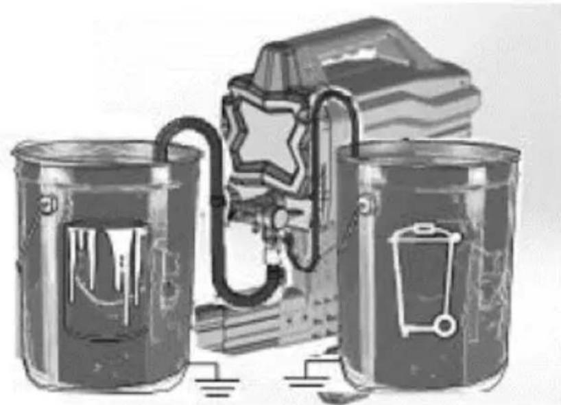
natural_image
Illustration of three metallic cans with embedded electrical components and a star symbol (no text or symbols present)f) Turn Prime/Spray valve down to PRIME position:

natural_image
Mechanical assembly diagram showing a shaft and housing with a curved arrow indicating rotation (no text or symbols)g) Plug the power supply cord into a properly grounded electrical outlet.
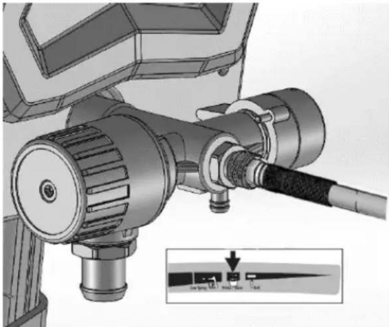
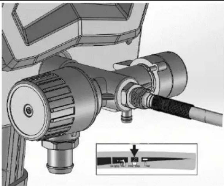
h) Align setting indicator with Prime/Clean setting on the pressure control knob:
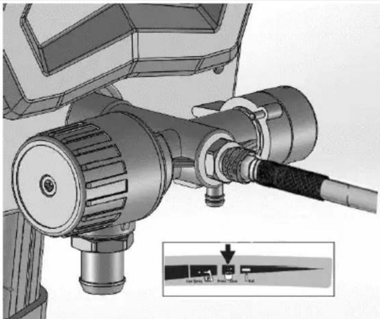
natural_image
Mechanical assembly diagram showing a motor and cable with labeled ports (no text or symbols present)i) Turn ON/OFF-switch to on ("I") position:
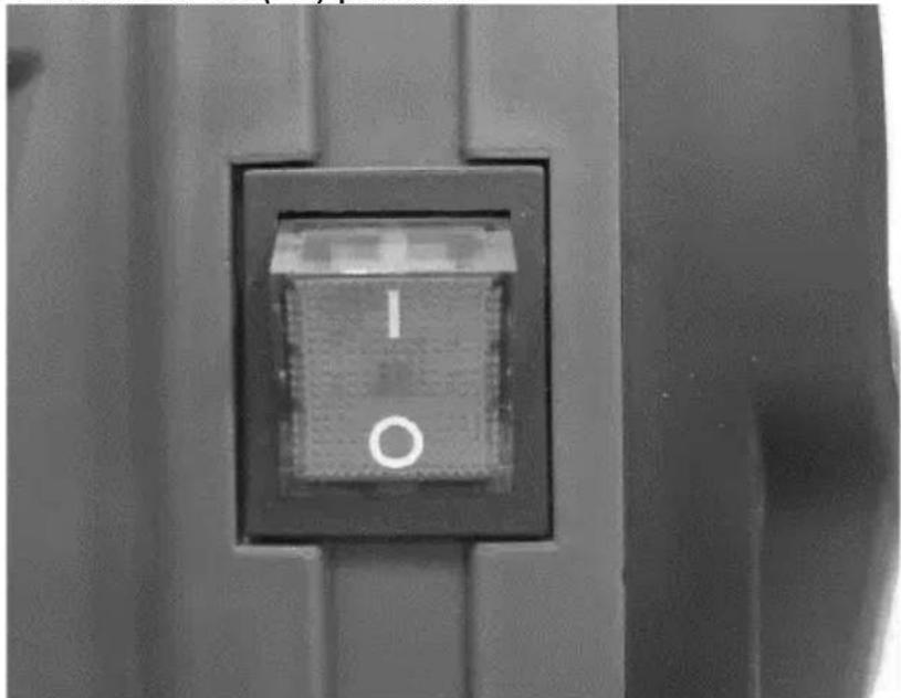
natural_image
Close-up of a black square button with white letter 'I' and 'O' on a metal panel (no additional text or symbols)j) When machine starts pumping, flushing solvent and air bubbles will be purged from system. Allow fluid to flow out of the drain tube into a waste pail for 30 to 60 seconds.
k) Turn ON/OFF-switch to off ("O") position.
I) Inspect for leaks. If leaks occur, perform "Pressure relief" procedure, then tighten all fittings and repeat start. If there are no leaks continue with next steps.
3.3.4 Filling the pump
a) Move the suction tube to paint pail and submerge suction tube in the paint:
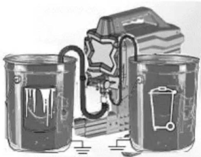
natural_image
Illustration of three cylindrical containers with embedded electrical components and a star-shaped device (no text or symbols)b) Turn ON/OFF-switch to on ("I") position.
c) Wait to see the paint coming out of drain tube.
d) Turn ON/OFF-switch to off ("O") position.
NOTE: some fluids may prime faster when the ON/OFF-switch is momentarily turned off, so the pump can slow down and stop. Turn the switch on and off several times if necessary.
3.3.5 Filling the gun and hose
a) Move suction tube to paint pail and submerge suction tube in paint. Hold the gun against waste pail. Point the gun into waste pail:
• Disengage the trigger lock.
• Pull and hold the gun trigger.
- Turn the Prime/Spray valve horizontal to SPRAY position.
- Turn the ON/OFF-switch to on ("I") position.
b) Trigger the gun into waste pail until only paint comes out of the gun.
c) Release the trigger. Engage trigger lock.
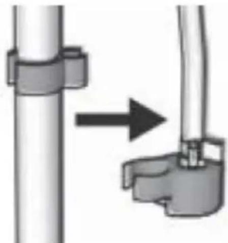
d) Transfer drain tube to paint pail and clip to suction tube:
NOTE: When motor stops, machine is ready to spray paint. If motor continues to run, machine hasn't been properly primed. Repeat "Filling the pump" and "Filling the gun and hose" procedures.
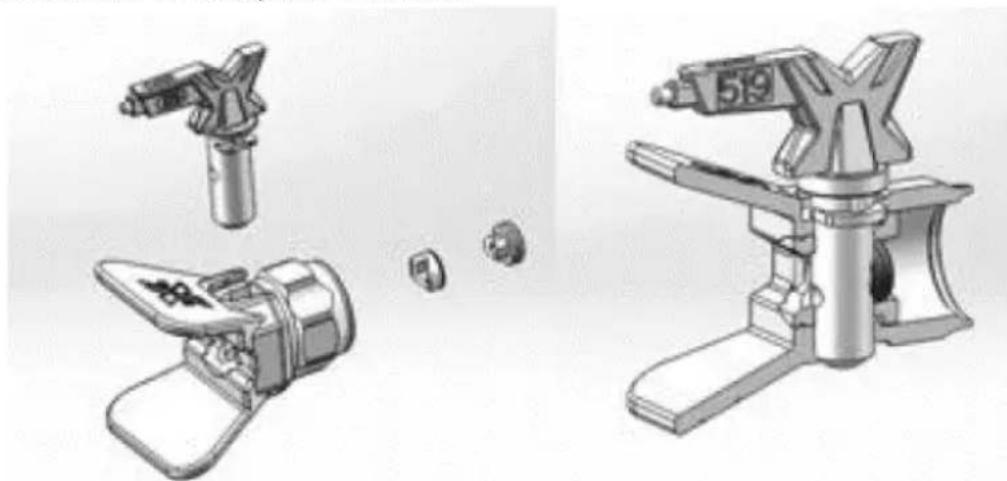
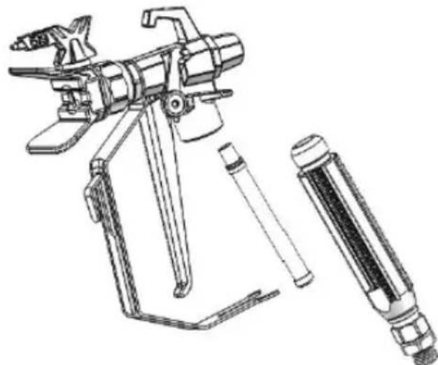
3.3.6 Spray tip installation
NOTE: to prevent spraying tip leaks make sure that the tip and tip guard are properly installed.
a) Perform "Pressure relief" procedure.
b) Engage trigger lock.
c) Verify that the spraying tip and tip guard parts are properly assembled in order shown on the picture below:
natural_image
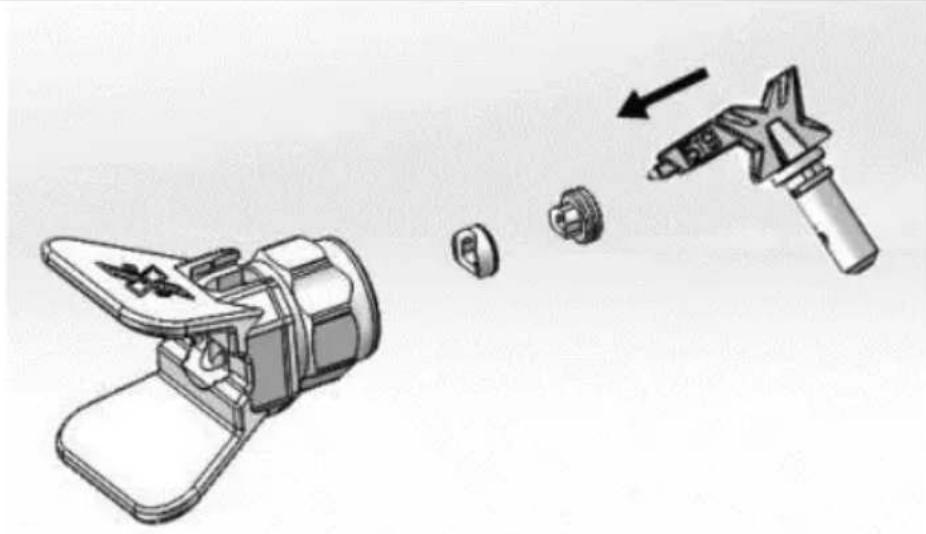
Illustration of three different types of mechanical devices with no visible text or symbols- Use a spray tip to align gasket and seal in the tip guard:
natural_image
Illustration of a hand tool and its internal components, showing a disassembled device and a handheld tool (no text or symbols present)- Spray tip must be pushed all the way into the tip guard:
natural_image
Illustration of a camera lens with a star-shaped lens and a downward arrow indicating compression or disassembly (no text or symbols present)- Turn the arrow shaped handle on the spray tip forward to the spray position:
natural_image
Two-step illustration showing a hand using a tool to adjust the camera frame (no text or symbols present)d) Screw spraying tip and tip guard assembly onto the gun and tighten them.
3.3.7 Adjusting pressure
The pressure control knob allows for infinite pressure adjustment. To reduce overspray and paint waste it is advised to start always at the
lowest pressure setting and then (if needed) increasing it to the minimum setting result that satisfies the needs:
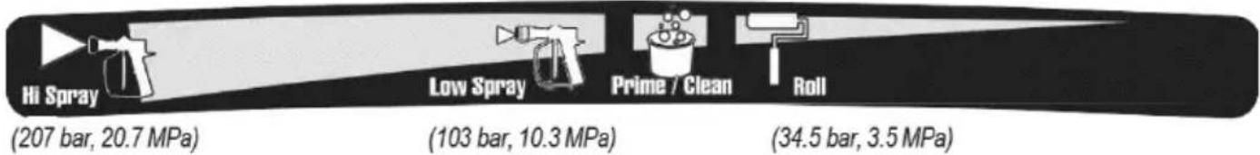
To choose the appropriate function, align the symbol on the pressure control knob with the setting indicator on the sprayer.
3.3.8 Tip and pressure selection
| Coatings | |||||
| Interior stains/ interior & exterior clears | Exterior solid stains | Primers | Interior latex paints | Exterior latex paints | |
| Spraying pressure→ | Low | High | High | High | High |
| Tip (hole) size↓ | |||||
| 0.28 mm (0.011 in) | X | ||||
| 0.33 mm (0.013 in) | X X X X | ||||
| 0.38 mm (0.015 in) | X X X X | ||||
| 0.43 mm (0.017 in) | X X X | ||||
| 0.48 mm (0.019 in) | X | ||||
- The included tip is for use in most paint spraying applications, but as with spray time the tip slowly wears and its hole enlarges. Starting with a tip hole size smaller than the maximum will allow to spray within the rated flow capacity of the sprayer.
- Use larger tip hole sizes with thicker coatings and smaller tip hole sizes with thinner coatings.
• Tips wear with use and need periodic replacement. - Tip hole size controls flow rate – the amount of paint that comes out of the gun.
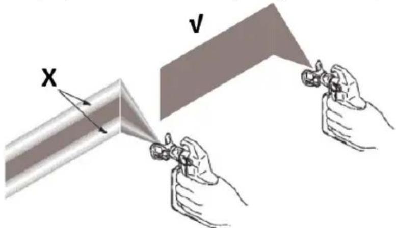
3.3.9 Spraying techniques
Use a piece of scrap cardboard to practice these basic spraying techniques before you begin spraying the surface.
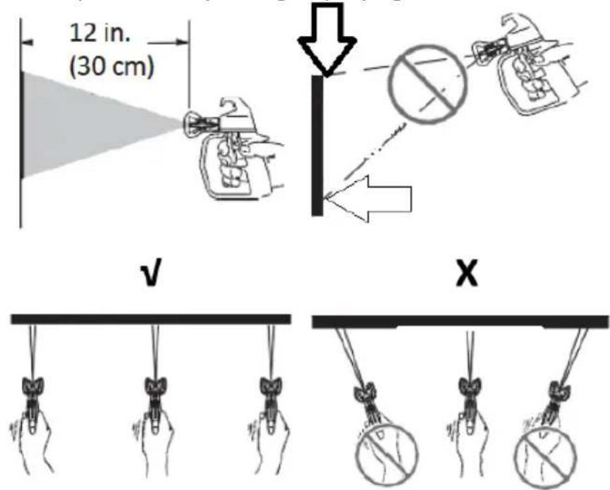
- Hold the gun 30 cm from the surface and aim straight at the surface (V). Tilting gun to direct spray angle causes uneven paint coat (X).
- Flex wrist to keep gun pointed straight (V). Fanning the gun to direct spray at an angle causes an uneven finish (X).
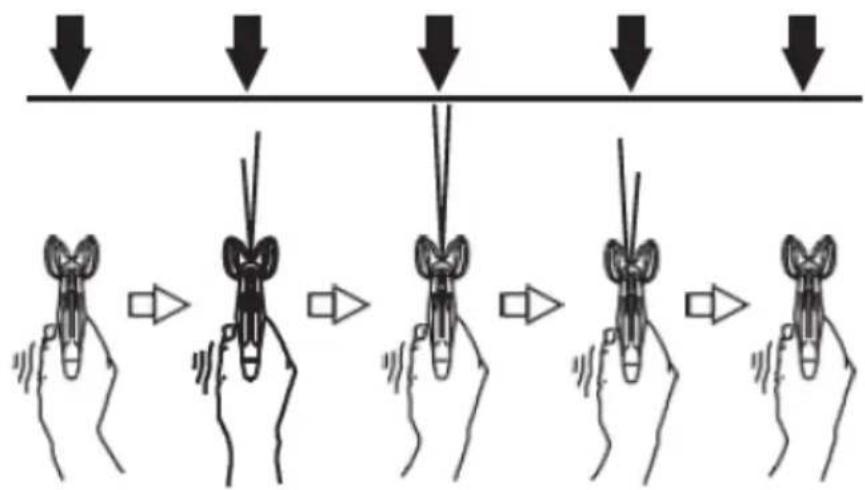
3.3.10 Triggering the gun
Pull the trigger after starting stroke and release trigger before the end of your stroke. Spraying gun must be moving when trigger is pulled and released:
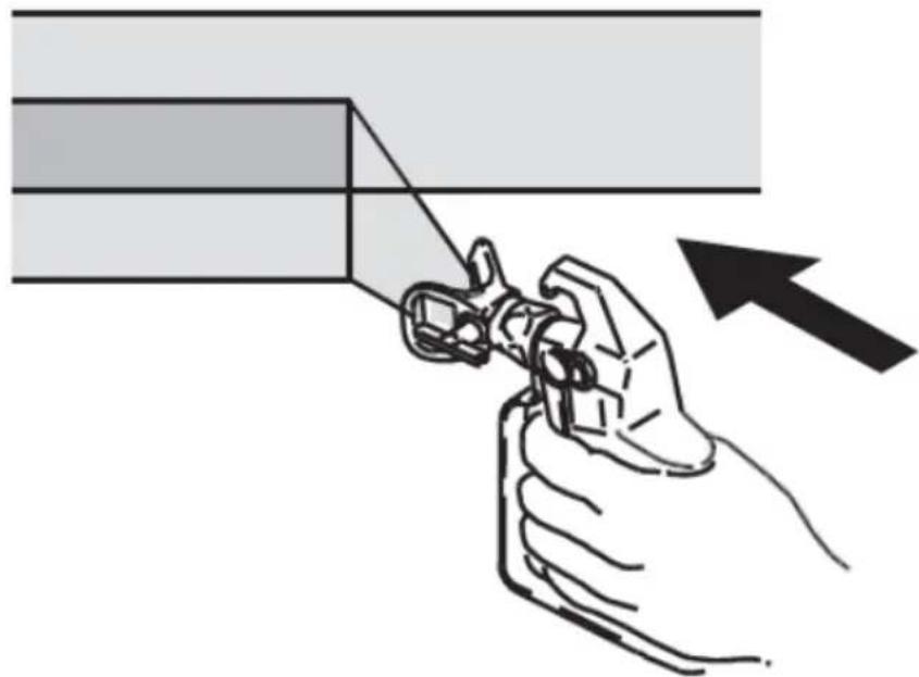
3.3.11 Aiming the gun
Aim centre of spraying of the gun at bottom edge of previous stroke, overlapping each stroke by half:
natural_image
Illustration of a hand using a tool to cut a rectangular object, with an arrow indicating the process (no text or symbols present)3.3.12 Spray pattern quality
A correct spray pattern is evenly distributed as it hits the surface.
- Spray should be atomized (evenly distributed, no gaps at edges):
X – pressure too low, tails and gaps at edges occur.
V - correct spray pattern.
If tails persist when spraying at the highest spray pressure:
- Spray tip may be worn.
• A smaller spray tip may be needed. - Spraying material may need to be thinned. If so than follow the material's manufacturer recommendations.
3.3.13 Clearing spraying tip clogs
In case when the particles or debris clog the spray tip, this machine is designed with a reversible spray tip that quickly and easily clears the particles without need to disassemble the sprayer.
See the "Strain the paint" section for additional information.
a) Engage the trigger lock. Rotate spray tip to unclog position. Disengage the trigger lock. Trigger the spraying gun at waste area to clear clog:
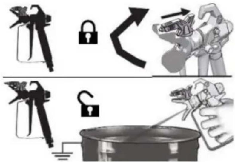
NOTE: if the spray tip is difficult to rotate when turning to the unclogging position, perform "Pressure relief" procedure, than turn the Prime/Spray valve to spray position and repeat step a).
b) Engage trigger lock. Rotate the spray tip back to spray position. Disengage trigger lock and continue spraying:
3.4. Cleaning and maintenance
a) Clean the pump/hose/spraying gun/spray tip thoroughly every day when you finish your painting job.
b) When pump is stored with non-freezing fluid pump damage will occur if water or latex paint freezes in pump.
c) Unplug the mains plug and allow the device to cool completely before each cleaning, adjustment or replacement of accessories, or if the device is not being used.
- Wait for the rotating elements to stop.
d) Use only non-corrosive cleaners to clean the surface.
e) After cleaning the device, all parts should be dried completely before using it again.
f) Store the unit in a dry, cool place, free from moisture and direct exposure to sunlight.
g) Do not spray the device with a water jet or submerge it in water.
h) Do not allow water to get inside the device through vents in the housing of the device.
i) Clean the vents with a brush and compressed air.
j) The device must be regularly inspected to check its technical efficiency and spot any damage.
k) Inspect motor shroud openings for blockage before each work start.
I) Inspect or clean the filter, fluid inlet strainer and gun filter before each work start.
m) Check hose for damage every time you spray. Do not attempt to repair hose if hose jacket or fittings are damaged. Do not use hoses shorter than about 7.5 m.
n) Use a soft cloth for cleaning.
o) Do not use sharp and/or metal objects for cleaning (e.g. a wire brush or a metal spatula) because they may damage the surface material of the appliance.
p) Spraying tips may require replacement after 57 litres or can last even through 227 litres, depending on abrasiveness of the paint.
3.4.1 Cleaning with a pail
For short term shutdown periods (over-night to 2 days) refer to “Short term storage” in other section. See sections “Cleaning fluid compatibility” for information on flushing/cleaning fluids and “Static grounding (Oil-based materials)” instructions.
a) Perform "Pressure relief" procedure.
b) Remove spraying tip and tip guard assembly from the gun and place it in waste pail:
natural_image
Two-step diagram showing hand operating a camera setup with tripod and tripod stand (no text or symbols)c) Lift the suction tube and drain tube from paint pail. Let the paint drain into the pail.
d) Separate the drain tube (smaller) from the suction tube (larger):
natural_image
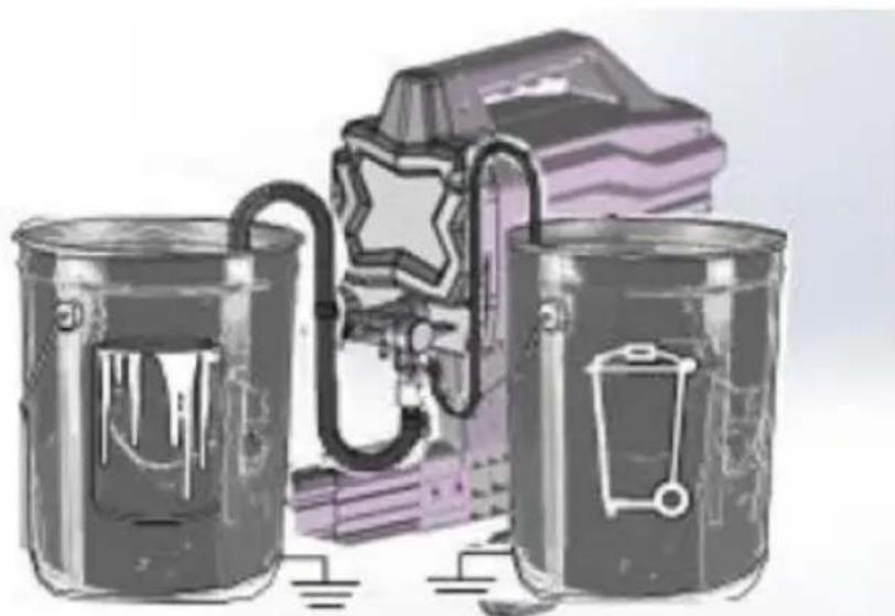
Diagram showing a pipe connection with a directional arrow indicating movement (no text or symbols present)e) Place empty waste and flushing fluid pails side by side.
f) Place the suction tube in flushing fluid. Use water for water based paint and mineral spirits or compatible oil-based flushing solvent for oil-based paint. Place the drain tube in waste pail:
natural_image
Illustration of three cans with embedded icons and a stylized object, no text or symbols presentg) Turn pressure control knob counter-clockwise to the Prime/Clean setting:
natural_image
Technical illustration of a mechanical device with attached cable and connector (no text or symbols)h) Turn Prime/Spray valve down to PRIME position:

natural_image
Mechanical assembly diagram showing a valve mechanism with a black curved arrow indicating rotational direction (no text or symbols present)i) Turn ON/OFF-switch to on ("I") position.
j) Flush until approximately 1/3 of the flushing fluid is emptied from the pail.
k) Turn ON/OFF-switch to off ("O") position.
NOTE: next step is for returning paint in hose to paint pail. For example a 7.5 m hose holds estimated approximately 0.5 Liter paint.
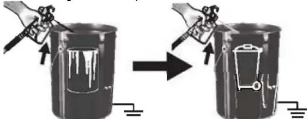
I) To recover paint in hose, point the gun into paint pail while holding gun firmly to the pail.
• Disengage trigger lock.
• Pull and hold gun trigger.
• Turn Prime/Spray valve horizontal to SPRAY position.
- Turn ON/OFF-switch to on ("I") position.
- Continue to hold the gun trigger until you see paint diluted with flushing fluid starting to come out of the gun.
m) While continuing to trigger gun, quickly move the gun to redirect spray into waste pail. Continue triggering gun into waste pail until flushing fluid dispensed from the gun is relatively clear.
n) Turn pressure control knob to the lowest setting.
o) Stop triggering gun. Engage the trigger lock.
p) Turn Prime/Spray valve down to PRIME position.
q) Turn ON/OFF-switch to off ("O") position.
3.4.2 Cleaning the gun
a) Clean gun fluid filter with water or flushing fluid and a brush every time you flush the system. Replace the gun filter if damaged.
natural_image
Technical line drawing of a spray gun with attached lever and handle (no text or symbols)b) Remove spray tip and tip guard and clean with water or flushing fluid and a brush.
flowchart
graph TD
    A["Feed Fuel"] --> B["Valve"]
    B --> C["Switch"]
    C --> D["Valve with Sensor"]
    D --> E["Product"]
c) Wipe paint off outside of the gun using a soft cloth moistened with water or flushing fluid.
3.4.3 Short term storage
a) Perform "Pressure relief" procedure.
b) Leave suction tube and drain tube in paint pail:
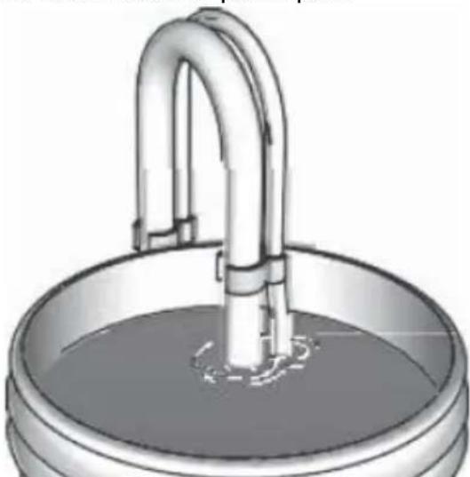
natural_image
Illustration of a metallic basin with a curved pipe inserted into the water (no text or symbols)c) Cover paint and pail tightly with plastic wrap:
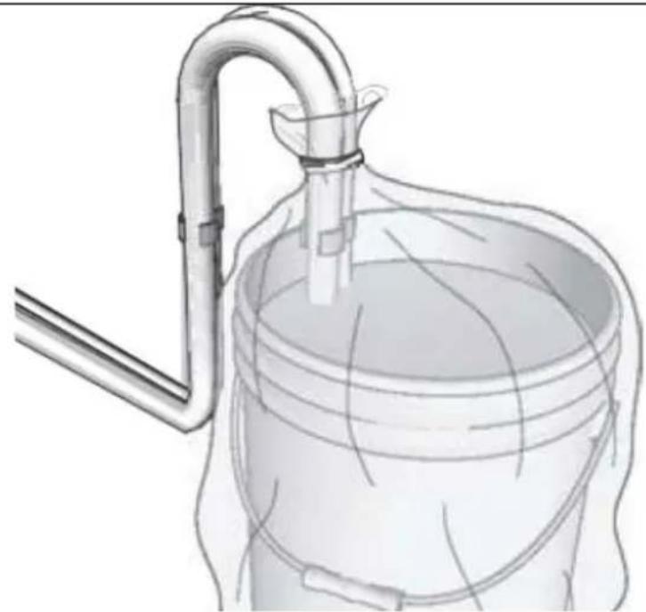
natural_image
Diagram of a laboratory apparatus with a funnel, tubing, and a container (no text or labels)d) Engage trigger lock.
natural_image
Illustration of a mechanical device with a lock icon and directional arrow, no text or symbols present.e) Leave the gun attached to the hose.
f) Remove tip and guard and clean them with water or flushing fluid and a brush.
g) Wipe the paint off outside of the gun using a soft cloth moistened with water or flushing fluid.
3.4.4 Long term storage (more than 2 days)
Pump fluid armour protects the sprayer against freezing and corrosion.
• Before storing sprayer make sure all water is drained out of it.
- Do not allow water to freeze in sprayer.
- Do not store the sprayer under pressure.
- Store the machine indoors.
a) Perform “Pressure relief” procedure.
b) Place the suction tube in pump storage fluid bottle and drain tube in waste pail.
c) Turn Prime/Spray valve down to PRIME position:
natural_image
Mechanical component with a curved arrow indicating rotational direction (no text or symbols present)d) Turn ON/OFF-switch to on ("I") position.
e) Turn pressure control knob clockwise until the machine turns on and starts pumping.
f) When storage fluid comes out of the drain tube (5-10 seconds) turn ON/OFF-switch to off ("O") position.
g) Turn Prime/Spray valve horizontal to SPRAY position to keep storage fluid in sprayer during storage:
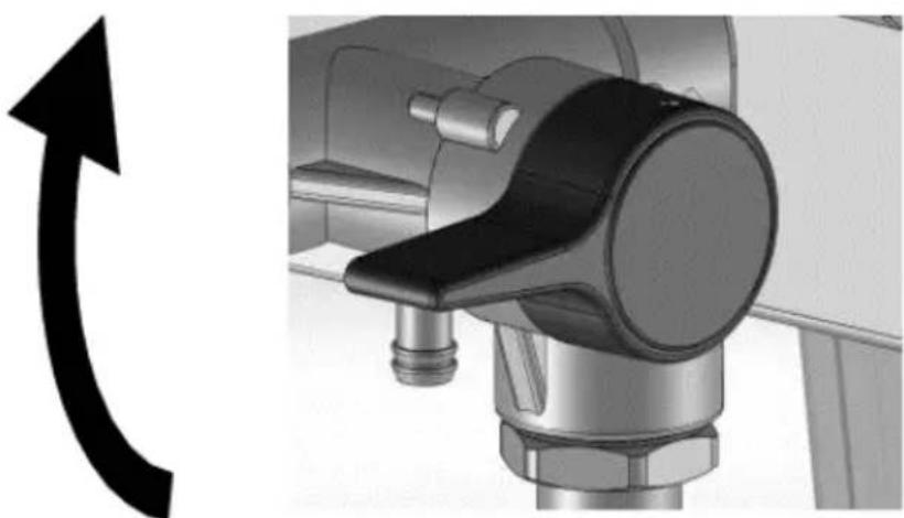
natural_image
Mechanical component with a curved arrow indicating rotation or direction (no text or symbols present)h) Leave the gun attached to hose.
i) Remove the tip and guard and clean with water or flushing fluid and a brush.
j) Wipe paint off outside of the gun using a soft cloth moistened with water or flushing fluid.
k) Secure a plastic bag around suction and drain tube to catch any drips:
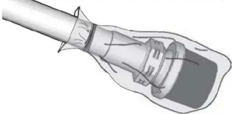
natural_image
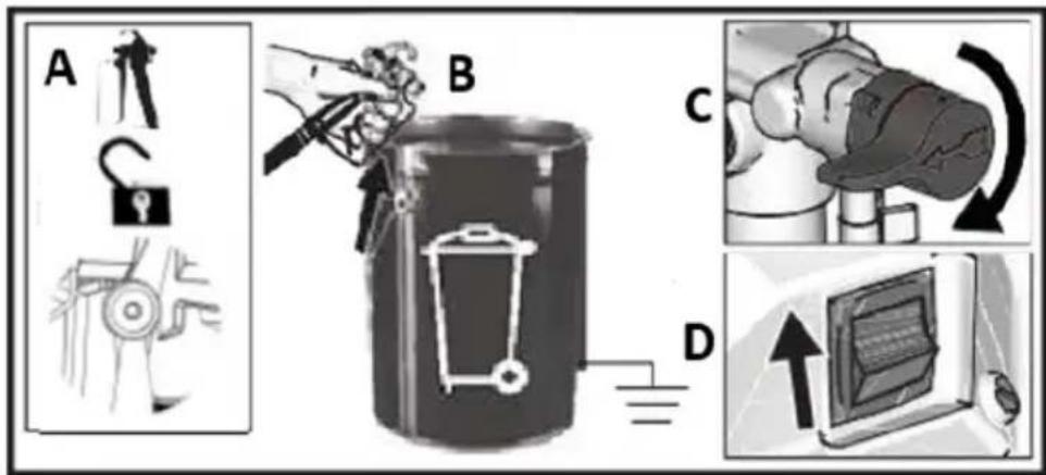
Illustration of a medical or laboratory procedure showing a tool inserted into a device (no text or symbols visible)3.4.5 Static grounding (oil-based paints)
- Always use a metal pail for oil-based materials requiring flushing with compatible oil-based flushing solvents when sprayer is flushed or pressure is relieved.
- Use only conductive metal pails, placed on a grounded surface such as concrete.
- Do not place pail on a non-conductive surface such as paper or cardboard which interrupts grounding continuity.
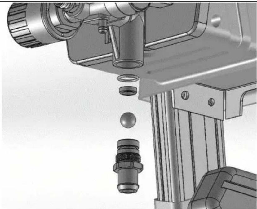
3.4.6 Inlet valve removal and installation
If the inlet valve is clogged or stuck, remove the valve assembly and clean thoroughly or replace.
a) Remove the suction tube or hopper from sprayer.
b) Loosen the inlet valve and remove it:
a) Remove the suction tube or hopper from sprayer. b) Loosen the inlet valve and remove it:
natural_image
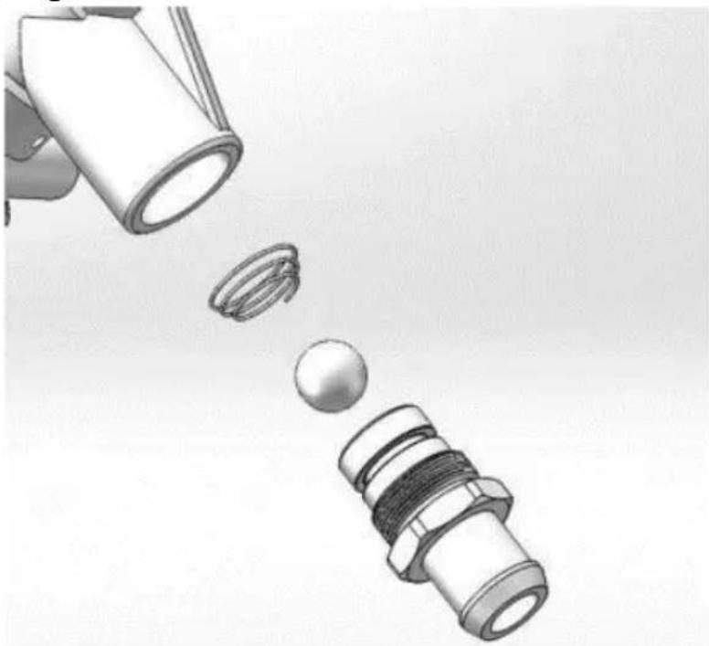
Mechanical assembly diagram showing a mechanical component with bolts and a ball, no visible text or symbolsCAUTION: do not loose the ball and spring inside the inlet valve assembly. It may fall out when the inlet valve is removed. Pump will not prime without the ball and spring.
c) Clean any debris and dried paint from the cavity and replace the ball with spring. Tighten pump inlet valve using proper tool on the frame.
d) Please pay attention to the conical spring direction when installing the ball and conical spring:
natural_image
Illustration of a mechanical component with three parts, one emitting a ball (no text or symbols)3.4.7 Cleaning fluids compatibility
- When spraying water-based materials, flush the system thoroughly with water.
- When spraying oil-based materials, flush the system thoroughly with mineral spirits or compatible, oil-based flushing solvent.
- To spray water-based materials after spraying oil-based materials, flush the system thoroughly with water first. The water flowing out of drain tube should be clear and solvent-free before you begin spraying the water-based material.
- To spray oil-based materials after spraying water-based materials, flush the system thoroughly with mineral spirits or a compatible oil based flushing solvent first. The solvent flowing out of the drain tube should not contain any water. When flushing with solvents always follow “Static grounding” Instructions (oil-based materials).
- To avoid fluid splashing back on your skin or into your eyes, always aim gun at inside wall of pail.
DISPOSING OF USED DEVICES
Do not dispose of this device in municipal waste systems. Hand it over to an electric and electrical device recycling and collection point. Check the symbol on the product, instruction manual and packaging. The plastics used to construct the device can be recycled in accordance with their markings. By choosing to recycle you are making a significant contribution to the protection of our environment.
Contact local authorities for information on your local recycling facility.
TROUBLESHOOTING
| Problem | Possible cause | Solution |
| Motor does not run:(verify if machine is plugged in, and ON/OFF switch is on) | Pressure control is set at zero pressure. | Turn the pressure control knob clockwise to increase pressure setting. |
| Electric outlet not providing power. | Test outlet with known working device.Reset circuit breaker or replace fuse.Find working outlet.Reset building circuit breaker or replace fuse. | |
| Extension cord is damaged. | Replace extension cord. | |
| Machine's electric cord is damaged. | Check for broken insulation or wires. Replace electric cord if damaged. | |
| Pump is seized (paint hashardened in pump or water is frozen in pump.) | Turn ON/OFF switch off andunplug sprayer from outlet.If frozen do NOT try to start The machine until it is completely thawed or it may damage the motor, control board and/or drivetrain.Place the machine in warm area for several hours. Check for free moving pump by removing shroud and spinning fan.If not frozen, check for hardened paint in pump.If motor does not turn with pump removed, contact manufacturers customer care. | |
| Motor or control board is damaged. | Contact manufacturers customer care. | |
| Machine runs, but pump does not prime or loses prime while in use.(Pump cycles but does not pump paint or build pressure.) | Inlet valve check ball is stuck. | Press Push Prime button to dislodge the ball allowing pump to prime properly. |
| Prime/Spray valve is in SPRAY position. | Turn Prime/Spray valve down to PRIME position until paint exits drain tube. The pump is now primed. | |
| The pump was not primed with flushing fluid. (Thick fluids may not prime if not Initially primed with flushing fluid.) | Remove suction tube from paint. Prime pump with oil or water-based flushing fluid. | |
| Debris in paint. | Strain the paint. | |
| Thick or “sticky” paint. | Some fluids may prime faster if the ON/OFF-switch is momentarily turned off so the pump can slow and stop. Turn ON/OFF-switch on and off Several times if necessary. | |
| Inlet valve check ball or seat | Remove inlet fitting. Clean or | |
| is dirty. | replace the ball and seat. | |
| Suction tube is leaking. | Inspect suction tube connection for cracks or vacuum leaks. | |
| Outlet valve check ball is stuck. | Unscrew outlet valve, remove, and clean assembly. | |
| Prime/Spray valve is worn or obstructed with debris. | Take sprayer to authorized service centre. | |
| Pump is primed, but cannot achieve a good spray pattern. | Spray tip may be partially clogged. | Clear spray tip clog. |
| Reversible spray tip is in UNCLOG position. | Rotate arrow-shaped handle on spray tip so it points forward to SPRAY position. | |
| Debris in paint. | Strain the paint. | |
| Pressure is set too low. | Align pressure control knob setting indicator to desired spray setting. | |
| Spraying gun fluid filter is clogged. | Clean or replace the gun fluid filter. | |
| Spray tip selected is too large for capability of sprayer. | Replace tip. | |
| Spray tip is worn beyond the capability of the sprayer. | Replace tip. | |
| Spray tip gasket and seal worn or missing. | Replace gasket and seal. | |
| Inlet strainer is clogged or suction tube is not immersed in paint. | Clean debris off inlet strainer and make sure suction tube is immersed in paint. | |
| Extension cord is too long or not heavy enough gauge. | Replace extension cord. | |
| Inlet pump valve or outlet pump valve is worn or clogged with debris. | Check for worn or contaminated inlet valve or outlet valve.- Prime sprayer with paint- Trigger gun momentarily- When trigger is released, pump should cycle momentarily and stop- If pump continues to cycle, |
EN
| Material is too thick. | pump valves may be worn or contaminated with debris - Clean and reinstall valves. Thin material. Follow manufacturers recommendations. | |
| Airless hose is too long (if extra section was added). | Remove section of airless hose. | |
| Spraying gun stopped spraying while trigger is pulled. | Spray tip is clogged. | Clear spray tip clog. |
| Machine lost prime. | See troubleshooting section “Machine runs, but pump does not prime or loses prime while in use.” | |
| When paint is sprayed, it runs down the wall or sags. | Material is going on too thick. | Move gun faster.Choose a spray tip with smaller hole size.Choose s spray tip with wider fan.Make sure gun is far enough from surface. |
| When paint is sprayed, coverage is inadequate. | Material is going on too thin. | Move gun slower.Choose a spray tip with larger hole size.Choose a spray tip with narrower fan.Make sure gun is close enough to surface. |
| Fan pattern varies dramatically while spraying. | Pressure control switch is worn and causing excessive pressure variation. | Take sprayer to authorized service center. |
| Cannot trigger the spraying gun. | Spraying gun trigger lock is engaged. | Rotate trigger lock to disengage the trigger lock. |
| Paint is coming out of pressure control switch. | Pressure control switch is worn. | Take machine to an authorized service center. |
| Paint is leaking through drain tube. | Machine is over pressurizing. | Take the machine to an authorized service centre. |
| Paint leaks down outside of pump. | Pump packings are worn. | Replace pump packings. |
| Motor is hot and | Vent holes in enclosure are | Keep vent holes clear of |
EN
| runs intermittently.Motor automatically shuts off due to excessive heat. Damage can occur if cause is not corrected. | plugged or sprayer is covered. | obstructions and overspray and keep sprayer open to air. |
| Extension cord is too long or not a heavy enough gauge. | Replace extension cord. | |
| Unregulated electrical generator being used has excessive voltage. | Use electrical generator with a proper voltage regulator. | |
| Motor needs to be replaced. | Take the machine to an authorized service centre. |
natural_image
Two industrial water purifier machines with hoses and wheels, shown from different angles (no visible text or labels)natural_image
Mechanical assembly diagram showing a cam or probe inserted into a housing with a tool handle (no text or symbols visible)natural_image
Mechanical assembly diagram showing a robotic arm and articulated joints (no text or labels)natural_image
Illustration of a robotic device with a lock icon and directional arrow, no text or symbols present.natural_image
Two-step diagram showing hand operating a camera setup with tool, no text or symbols presentnatural_image
Technical illustration of a mechanical device with a cable and adjustment knob, showing no text or symbols.natural_image
Illustration of a bucket pouring liquid into a container with a lid, alongside a close-up of the interior of a water bucket filled with ice (no text or symbols)natural_image
Close-up of a black electrical switch with a circular indicator light on the side panel (no text or symbols visible)natural_image
Technical illustration of mechanical components with lock and washer symbols (no text or labels)natural_image
Mechanical assembly diagram showing a motor and cable connector with a close-up inset of the device (no text or symbols visible)natural_image
Mechanical assembly diagram showing pipe connection and directional arrow (no text or symbols)natural_image
Illustration of a hand using a tool to lift a cylindrical component, with an upward arrow indicating motion (no text or symbols)natural_image
Illustration of three metallic cans with embedded electrical components and a star symbol (no text or symbols present)natural_image
Mechanical assembly diagram showing a valve mechanism with a black curved arrow indicating rotational direction (no text or symbols present)natural_image
Mechanical assembly diagram showing a motor connected to a cable with a labeled component inset (no text or symbols present)natural_image
Close-up of a black square button with white letter 'I' and 'O' on a metal panel (no additional text or symbols)natural_image
Illustration of three cylindrical containers with embedded electrical components and a star symbol (no text or symbols present)natural_image
Illustration of a handheld device with internal components and a hand holding a tool, showing motion direction (no text or symbols)natural_image
Illustration of a mechanical device with a downward arrow indicating compression or disassembly (no text or symbols present)natural_image
Two-step illustration showing a hand using a tripod to adjust the camera and press device (no text or symbols present)3.3.11 Celowanie pistoletem
natural_image
Illustration of a hand using a tool to cut a rectangular object, with an arrow indicating the process (no text or symbols present)natural_image
Two-step illustration showing hand operating a camera setup with tripod and binoculars (no text or symbols)natural_image
Diagram showing a pipe connection with a directional arrow indicating movement (no text or symbols present)natural_image
Illustration of two cans with paint dripping, connected by a ladder to a stylized backpack and battery (no text or symbols)natural_image
Technical illustration of a mechanical device with attached cable and connector (no text or symbols visible)natural_image
Mechanical assembly diagram showing a rotating component with a curved arrow indicating rotational motion (no text or symbols present)natural_image
Technical line drawing of a spray gun assembly with two components (no text or symbols)natural_image
3D illustration of a mechanical component with a downward arrow indicating compression or disassembly (no text or symbols)
natural_image
Mechanical component with a curved arrow indicating rotational direction (no text or symbols present)natural_image
Mechanical component with a curved arrow indicating rotation or direction (no text or symbols present)natural_image
Illustration of a medical or laboratory procedure showing a tube inserted into a device (no text or symbols present)natural_image
Illustration of a mechanical component with three parts, one emitting a ring and the other falling into a sphere (no text or symbols)
natural_image
Line drawing of a mechanical pump or cart with wheels and a handle, labeled 'R' (no text or symbols on the diagram itself)

natural_image
Coiled wire with two small rectangular components, labeled 'N' at the end (no other text or symbols)natural_image
Mechanical assembly diagram showing a valve and actuator component (no text or symbols visible)natural_image
Mechanical assembly diagram showing a robotic arm and articulated joints (no text or labels)natural_image
Illustration of a robotic device with a lock icon and directional arrow (no text or symbols)natural_image
Two-step diagram showing hand operating a camera setup with tool, no text or symbols presentnatural_image
Technical illustration of a mechanical device with a close-up inset showing a component labeled 'no Drip' and 'no Max', no text or symbols present.natural_image
Illustration of a bucket pouring liquid into a container, and a close-up of a textured material inside a bucket (no text or symbols)natural_image
Close-up of a black electrical switch with a circular button, mounted on a metal door (no visible text or symbols)natural_image
Technical illustration of mechanical components with lock and washer symbols (no text or labels)natural_image
Mechanical assembly diagram showing a motor and cable connector with a close-up inset of the device (no text or symbols visible)natural_image
Mechanical assembly diagram showing pipe connection and directional arrow (no text or symbols)natural_image
Illustration of a hand using a tool to lift a cylindrical component, with an upward arrow indicating motion (no text or symbols)natural_image
Illustration of three cylindrical cans with embedded electrical components and a star-shaped object (no text or symbols)natural_image
Mechanical component with a curved arrow indicating rotational direction (no text or symbols present)natural_image
Mechanical assembly diagram showing a motor connected to a cable with a close-up inset illustrating the internal components (no text or symbols present)natural_image
Close-up of a black square button with white letter 'I' and 'O' on a metal panel (no additional text or symbols)natural_image
Illustration of three paint cans with different internal components, including a star-shaped device and a battery (no text or symbols)natural_image
Illustration of a mechanical device with exploded view and close-up views (no text or symbols)natural_image
Illustration of a hand tool and its internal components, showing a disassembled device and a handheld tool (no text or symbols present)natural_image
Illustration of a mechanical device with a downward arrow and star symbol (no text or labels)natural_image
Two-step illustration showing a hand using a tripod to adjust the camera and press device (no text or symbols present)natural_image
Illustration of a hand using a tool to cut a rectangular object, with an arrow indicating the process (no text or symbols present)3.4. ČISTĚNÍ A ÚDRŽBA
natural_image
Two-step illustration showing hand tool application on a tripod, with no visible text or symbolsnatural_image
Diagram showing a pipe connection with a directional arrow indicating movement (no text or symbols present)natural_image
Illustration of two cans with paint dripping, connected by a ladder to a stylized backpack and stack of books (no text or symbols)natural_image
Technical illustration of a mechanical device with attached cable and connector (no text or symbols)natural_image
Mechanical assembly diagram showing a valve mechanism with a black curved arrow indicating rotational direction (no text or symbols present)natural_image
Technical line drawing of a precision surveying instrument with tripod and base components (no text or symbols)natural_image
Illustration of a mechanical component with a curved handle and central shaft, no text or symbols presentnatural_image
Mechanical assembly diagram showing a valve mechanism with a curved arrow indicating rotation (no text or symbols present)natural_image
Mechanical component with a curved arrow indicating rotation or direction (no text or symbols present)natural_image
Illustration of a hand holding a cylindrical object with a flanged handle, no text or symbols presentnatural_image
Mechanical assembly diagram showing a mechanical component with bolts and a ball, no visible text or symbolsnatural_image
Illustration of a mechanical component with three parts, showing a funnel pouring into a socket and a threaded connector (no text or symbols)natural_image
Two industrial electric spray machines with hoses and wheels, shown from different angles (no text or symbols visible)natural_image
Mechanical assembly diagram showing a valve and connecting rod (no text or symbols)natural_image
Illustration of a robotic arm with articulated joints and control panel (no text or symbols)natural_image
Illustration of a robotic device with a lock icon and directional arrow (no text or symbols)natural_image
Two-step diagram showing hand operating a camera setup with tool, no text or symbols presentnatural_image
Technical illustration of a mechanical device with a close-up inset showing a labeled control panel (no text or symbols present)natural_image
Two-step diagram showing hand operating a camera setup with tool, no text or symbols presentFR
natural_image
Illustration of a bucket pouring liquid into a container, and a close-up of a plastic bag filled with material (no text or symbols)3.3.3 Décompression
natural_image
Close-up of a black electrical switch with a circular button, mounted on a wall (no visible text or symbols)natural_image
Technical illustration of mechanical components with lock and washer symbols (no text or labels)natural_image
Mechanical assembly diagram showing a motor and cable with a close-up inset of the component (no text or symbols visible)natural_image
Mechanical assembly diagram showing pipe connection and directional arrow (no text or symbols)natural_image
Illustration of a hand using a pliers to lift a cylindrical container with an upward arrow, next to a battery (no text or symbols)natural_image
Illustration of three metallic cans with embedded electrical components and a star-shaped device (no text or symbols)natural_image
Mechanical assembly diagram showing a valve mechanism with a curved arrow indicating rotational direction (no text or symbols present)natural_image
Mechanical assembly diagram showing a motor and cable connector with a zoomed-in detail view (no text or symbols)natural_image
Close-up of a black square button with white 'I' and 'O' symbols, mounted on a metal panel (no readable text or numbers)natural_image
Illustration of three cylindrical containers with embedded electrical components and a star-shaped object (no text or symbols)natural_image
Illustration of three mechanical devices with no visible text or symbolsnatural_image
Illustration of a handheld device with internal components and a hand tool, showing motion direction (no text or symbols)natural_image
Illustration of a camera with a downward arrow indicating compression or disassembly (no text or symbols present)natural_image
Two-step illustration showing a hand using a tool to adjust the device, with no visible text or symbols.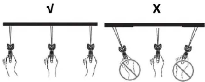
natural_image
Two-step diagram showing hand operating a camera setup with tool, no text or symbols presentnatural_image
Diagram showing a pipe connection with a directional arrow indicating movement (no text or symbols present)natural_image
Illustration of three cans with paint and a stylized lock, no text or symbols presentnatural_image
Technical illustration of a mechanical device with attached cable and connector (no text or symbols)natural_image
Mechanical assembly diagram showing a valve mechanism with a curved arrow indicating rotational direction (no text or symbols present)natural_image
Technical line drawing of a spray gun assembly with two components (no text or symbols)flowchart
graph TD
    A["Tool Injection"] --> B["Adder"]
    B --> C["Transfer to Gas Gun"]
    C --> D["Order to Painted Gear"]
    D --> E["Recycling to Tank"]
    E --> F["Final Collection"]
natural_image
Illustration of a metallic pipe fitting with a curved handle, partially submerged in liquid (no text or symbols)natural_image
Diagram of a laboratory apparatus with a container and tubing, no visible text or symbolsnatural_image
Illustration of a mechanical device with a lock icon and directional arrow, no text or symbols present.natural_image
3D illustration of a mechanical component with a downward arrow indicating compression or disassembly (no text or symbols)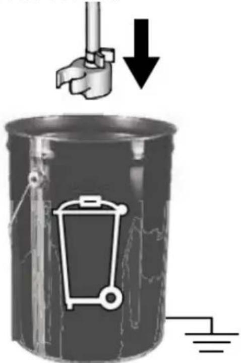
natural_image
Mechanical component with a curved arrow indicating rotational direction (no text or symbols present)natural_image
Mechanical assembly diagram showing a rotating component with a curved arrow indicating rotation (no text or symbols present)natural_image
Illustration of a medical or laboratory procedure showing a tool inserted into a device (no text or symbols present)natural_image
Mechanical assembly diagram showing a mechanical component with a ball and threaded fitting (no text or symbols)natural_image
Illustration of a mechanical component with three parts, one emitting a ring and the other falling into a sphere (no text or symbols)natural_image
Two industrial water purifier machines with hoses and wheels, shown from different angles (no visible text or labels)natural_image
Mechanical assembly diagram showing a cam or probe inserted into a housing with a tool handle (no text or symbols visible)natural_image
Mechanical assembly diagram showing a robotic arm and articulated joints (no text or labels)natural_image
Illustration of a robotic device with a lock icon and directional arrow (no text or symbols)natural_image
Two-step diagram showing hand operating a camera setup with tool, no text or symbols presentnatural_image
Technical illustration of a mechanical device with a cable and adjustment knob, showing no text or symbols.natural_image
Illustration of a bucket pouring liquid into a container with a lid, alongside a close-up of the interior of a water bucket filled with ice (no text or symbols)natural_image
Close-up of a black electrical switch with a circular indicator light on the side panel (no text or symbols visible)natural_image
Technical illustration of mechanical components with lock and ring symbols (no text or labels)natural_image
Technical illustration of a mechanical device with a cable and adjustment knob, showing no readable text or symbols.natural_image
Mechanical assembly diagram showing pipe connection and directional arrow (no text or symbols)natural_image
Illustration of a hand using a tool to lift a cylindrical component, with an upward arrow indicating motion (no text or symbols)natural_image
Illustration of three metallic cans with embedded electrical components and a star symbol (no text or symbols present)natural_image
Mechanical assembly diagram showing a valve mechanism with a curved arrow indicating rotational direction (no text or symbols present)natural_image
Mechanical assembly diagram showing a motor connected to a cable with a close-up inset illustrating the internal components (no text or symbols present)natural_image
Close-up of a black square button with white letter 'I' and 'O' on a metal panel (no additional text or symbols)natural_image
Illustration of three cylindrical containers with embedded electrical components and a star-shaped device (no text or symbols)natural_image
Illustration of three mechanical devices with no visible text or symbolsnatural_image
Illustration of a handheld device with internal components and a hand tool, showing motion of movement (no text or symbols)natural_image
Mechanical device with a downward arrow indicating compression or disassembly (no text or symbols present)natural_image
Two-step diagram showing hand operating a camera setup with tool, no text or symbols present(207 bar, 20.7 MPa)
(103 bar, 10.3 MPa)
(34.5 bar, 3.5 MPa)
3.3.11 Puntare la pistola
natural_image
Illustration of a hand using a tool to cut a rectangular object, with an arrow indicating the process (no text or symbols present)natural_image
Two-step diagram showing hand tool application on a tripod, with arrows indicating the process (no text or symbols present)natural_image
Diagram showing a pipe connection with a directional arrow indicating movement (no text or symbols present)natural_image
Illustration of three paint cans with different paint styles and a stylized backpack (no text or symbols)natural_image
Technical line drawing of a spray gun assembly with two components (no text or symbols)natural_image
Illustration of a metallic pipe fitting with a curved handle, partially submerged in liquid (no text or symbols)natural_image
Diagram of a laboratory apparatus with a container and tubing, no visible text or symbolsnatural_image
Illustration of a mechanical device with a lock icon and directional arrow, no text or symbols present.natural_image
3D illustration of a mechanical component with a downward arrow indicating force or direction (no text or symbols)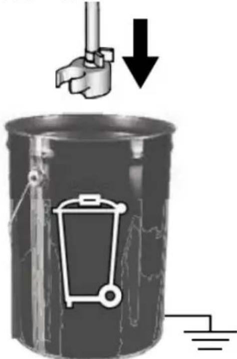
natural_image
Mechanical component diagram showing a valve assembly with a curved arrow indicating rotation (no text or symbols present)natural_image
Mechanical component diagram showing a lever mechanism with an arrow indicating rotational direction (no text or symbols present)natural_image
Illustration of a medical or laboratory procedure showing a tool inserted into a device (no text or symbols visible)3.4.5 Messa a terra statica (vernici a olio)
natural_image
Mechanical assembly diagram showing a mechanical component with a ball and threaded fitting (no text or symbols)natural_image
Illustration of a mechanical component with three parts, one emitting a ring and the other falling into a sphere (no text or symbols)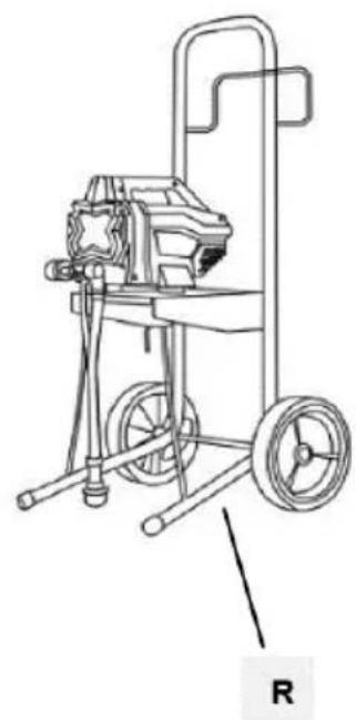
natural_image
Line drawing of a mechanical pump or cart with wheels and a handle, labeled 'R' (no text or symbols on the device itself)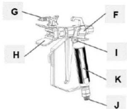
natural_image
Coiled wire with two small rectangular components, labeled 'N' at the end (no other text or symbols)natural_image
Two industrial pressure irrigation machines with hoses and wheels, shown from different angles (no text or symbols visible)natural_image
Mechanical assembly diagram showing a valve and connecting rod (no text or symbols)natural_image
Mechanical assembly diagram showing a robotic arm and articulated joints (no text or labels)natural_image
Illustration of a robotic device with a lock icon and directional arrow (no text or symbols)natural_image
Two-step diagram showing hand operating a camera setup with tool, no text or symbols presentnatural_image
Technical illustration of a mechanical device with a close-up inset showing a labeled control panel (no text or symbols present)natural_image
Illustration of a bucket pouring liquid into a container with a lid, alongside a close-up of the interior portion of a bucket filled with ice (no text or symbols)natural_image
Close-up of a black electrical switch with a circular button, mounted on a wall (no visible text or symbols)natural_image
Technical illustration of mechanical components with lock and washer symbols (no text or labels)natural_image
Mechanical assembly diagram showing a motor and cable with a close-up inset of a control panel (no text or symbols visible)natural_image
Mechanical assembly diagram showing pipe connection and directional arrow (no text or symbols)natural_image
Illustration of a hand using a tool to lift a cylindrical component, with an upward arrow indicating motion (no text or symbols)natural_image
Illustration of three cylindrical cans with embedded paintbrushes and a star-shaped object, no text or symbols present.natural_image
Mechanical assembly diagram showing a valve mechanism with a curved arrow indicating rotational direction (no text or symbols present)natural_image
Mechanical assembly diagram showing a motor and cable connector with a zoomed-in detail view (no text or symbols)natural_image
Close-up of a black square button with white letter 'I' and 'O' on a metal panel (no additional text or symbols)natural_image
Illustration of three cylindrical containers with embedded electrical components and a star-shaped object (no text or symbols)natural_image
Illustration of three mechanical devices with no visible text or symbolsnatural_image
Illustration of a handheld device with internal components and a hand tool, showing motion direction (no text or symbols)natural_image
Illustration of a camera with a downward arrow indicating compression or disassembly (no text or symbols present)natural_image
Two-step illustration showing a hand using a tool to adjust the device, with no visible text or symbols.natural_image
Illustration of a hand using a tool to cut a rectangular object, with an arrow indicating the process (no text or symbols present)natural_image
Two-step diagram showing hand tool application on tripod and camera setup (no text or symbols)natural_image
Diagram showing a pipe connection with a directional arrow indicating movement (no text or symbols present)natural_image
Illustration of three cans with paint and a stylized lock, no text or symbols presentnatural_image
Technical illustration of a mechanical device with attached cable and connector (no text or symbols)natural_image
Mechanical assembly diagram showing a rotating component with a curved arrow indicating rotational motion (no text or symbols present)natural_image
Technical line drawing of a mechanical device with two components, no visible text or symbolsnatural_image
Illustration of a metallic pipe fitting with a curved handle, partially submerged in liquid (no text or symbols)natural_image
Diagram of a laboratory apparatus with a container and tubing, no visible text or symbolsnatural_image
Illustration of a mechanical device with a lock icon and directional arrow, no text or symbols present.natural_image
3D illustration of a mechanical component with a downward arrow indicating force or direction (no text or symbols)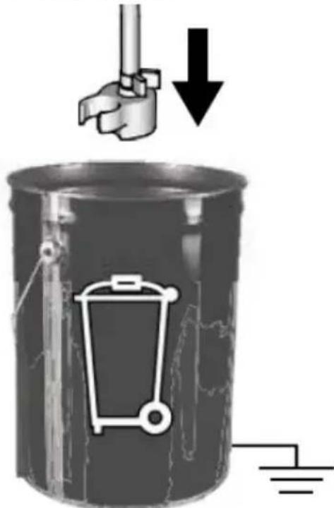
natural_image
Mechanical assembly diagram showing pipe connection and directional arrow (no text or symbols)natural_image
Mechanical assembly diagram showing a rotating component with a curved arrow indicating rotation (no text or symbols present)natural_image
Illustration of a medical or laboratory procedure showing a tool inserted into a device (no text or symbols visible)natural_image
Mechanical assembly diagram showing a mechanical component with a ball and threaded fitting (no text or symbols)natural_image
Illustration of a mechanical component with three parts, one emitting a ring and the other falling into a sphere (no text or symbols)natural_image
Two industrial water purifier machines with hoses and wheels, shown from different angles (no visible text or labels)natural_image
Mechanical device with attached lever and adjustment knob (no visible text or symbols)natural_image
Technical illustration of a mechanical device with a cable and adjustment knob (no text or symbols)natural_image
Illustration of a bucket pouring liquid into a container with a lid, alongside a close-up of the interior of a water bucket filled with ice (no text or symbols)natural_image
Close-up of a black electrical switch with a circular indicator light on the side panel (no text or symbols visible)natural_image
Technical illustration of mechanical components with lock and washer symbols (no text or labels)natural_image
Mechanical assembly diagram showing a motor and cable connector with a close-up inset of the device (no text or symbols visible)natural_image
Mechanical assembly diagram showing pipe connection and directional arrow (no text or symbols)natural_image
Illustration of a hand using a tool to lift a cylindrical component, with an upward arrow indicating motion (no text or symbols)natural_image
Illustration of three cylindrical cans with embedded electrical components and a star-shaped object (no text or symbols)natural_image
Mechanical assembly diagram showing a shaft and housing with a curved arrow indicating rotation (no text or symbols present)natural_image
Mechanical assembly diagram showing a motor and cable connector with a close-up inset of a device labeled 'Fire Spray', 'Power Tube', and 'Roll' (no text or symbols on main components)natural_image
Close-up of a black square button with white letter 'I' and 'O' on a metal panel (no readable text or symbols beyond basic markings)natural_image
Illustration of three cylindrical cans with paint dripping, connected by wires and a stylized object (no text or symbols)natural_image
Diagram showing a pipe connection with a paint bucket and valve mechanism, alongside a close-up of the pipe assembly (no text or symbols)natural_image
Illustration of three different mechanical devices with no visible text or symbolsnatural_image
Illustration of a hand tool and its internal components, showing a disassembled device and a handheld tool (no text or symbols present)natural_image
Illustration of a camera lens with a star-shaped lens and a downward arrow indicating compression or disassembly (no text or symbols present)natural_image
Two-step illustration showing a hand using a tool to adjust the camera frame (no text or symbols present)natural_image
Illustration of a hand using a tool to cut a rectangular object, with an arrow indicating the process (no text or symbols present)HU
natural_image
Two-step diagram showing hand operating a camera setup with tool, no text or symbols presentnatural_image
Diagram showing a pipe connection with a directional arrow indicating movement (no text or symbols present)natural_image
Illustration of three cans with paint dripping, featuring a stylized lock and book stack (no text or symbols)natural_image
Technical illustration of a mechanical device with attached tubing and a close-up inset showing internal components (no text or symbols)natural_image
Mechanical assembly diagram showing a valve mechanism with a black curved arrow indicating rotational direction (no text or symbols present)natural_image
Technical line drawing of a spray gun assembly with two components (no text or symbols)flowchart
graph TD
    A["Feed Fuel"] --> B["Valve Installation"]
    B --> C["Recycle to Bottle"]
    C --> D["Recycle to Tank"]
    D --> E["Final Collection"]
natural_image
Illustration of a metallic pipe fitting with a curved handle, partially submerged in liquid (no text or symbols)natural_image
Diagram of a laboratory apparatus with a container and tubing, no visible text or symbolsnatural_image
Illustration of a mechanical device with a lock icon and directional arrow, no text or symbols present.natural_image
3D illustration of a mechanical component with a downward arrow indicating compression or disassembly (no text or symbols)
natural_image
Mechanical assembly diagram showing a valve and housing with a curved arrow indicating rotation (no text or symbols present)natural_image
Mechanical component diagram showing a lever mechanism with an upward arrow indicator (no text or symbols present)natural_image
Illustration of a hand holding a cylindrical object with a flanged handle, no text or symbols presentnatural_image
Mechanical assembly diagram showing a disassembled component with a spherical part inserted (no text or symbols visible)natural_image
Exploded view of a mechanical component showing internal parts and a ball (no text or symbols)APPARATETS PLACERING
natural_image
Two industrial water purifier machines with hoses and wheels, shown from different angles (no text or symbols visible)natural_image
Mechanical assembly diagram showing a valve and connecting rod (no text or symbols)natural_image
Mechanical assembly diagram showing a robotic arm and linkage mechanism (no text or labels)natural_image
Illustration of a robotic device with a lock icon and directional arrow (no text or symbols)natural_image
Two-step diagram showing hand operating a camera setup with tool, no text or symbols presentg) Drej trykreguleringsknappen helt til venstre (mod uret) til den laveste indstilling:
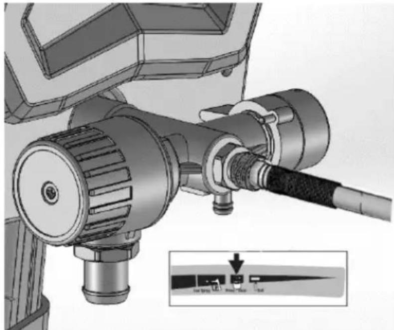
natural_image
Technical illustration of a mechanical device with a close-up inset showing a labeled control panel (no text or symbols present)natural_image
Illustration of a bucket pouring liquid into a container, and a close-up of a textured material inside a bucket (no text or symbols)3.3.3 Trykaflastning
natural_image
Close-up of a black electrical switch with 'I' and 'O' labels, mounted on a wall (no readable text or symbols beyond basic markings)natural_image
Technical illustration of mechanical components with lock and washer symbols (no text or labels)c) Sæt trykreguleringsknappen på den laveste indstilling:
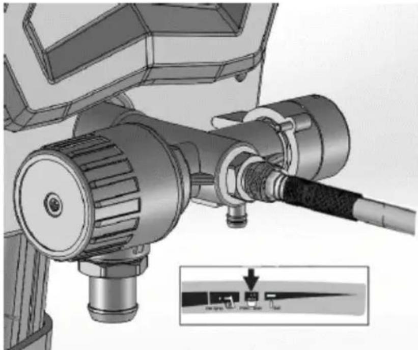
natural_image
Mechanical assembly diagram showing a motor and cable with a close-up inset of a control panel (no text or symbols visible)natural_image
Mechanical assembly diagram showing pipe connection and directional arrow (no text or symbols)natural_image
Illustration of a hand using a tool to lift a cylindrical component, with an upward arrow indicating motion (no text or symbols)natural_image
Illustration of three metallic cans with embedded electrical components and a star symbol (no text or symbols present)f) Drej Prime/Spray-ventilen ned til PRIME-position:
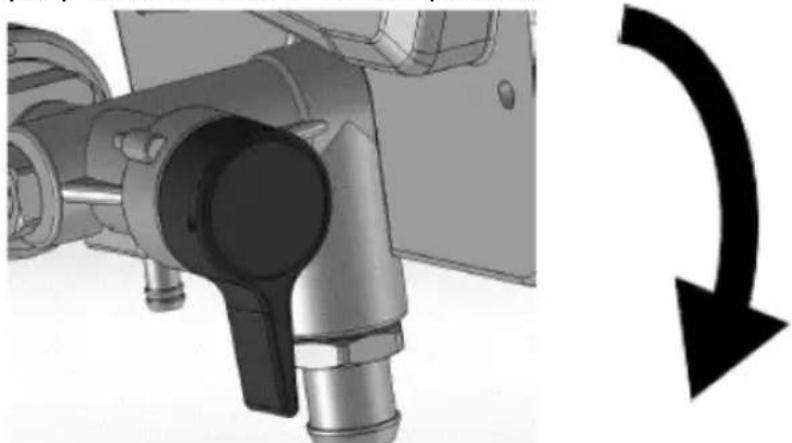
natural_image
Mechanical assembly diagram showing a valve mechanism with a curved arrow indicating rotational direction (no text or symbols present)natural_image
Mechanical assembly diagram showing a motor connected to a cable with a close-up inset illustrating the internal components (no text or symbols present)i) Drej ON/OFF-kontakten til positionen on ("I"):
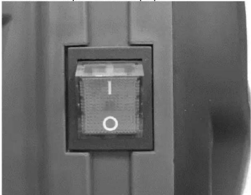
natural_image
Close-up of a black square button with white letter 'I' and 'O' on a metal panel (no readable text or symbols beyond basic markings)natural_image
Illustration of three cylindrical containers with embedded electrical components and a star-shaped device (no text or symbols)natural_image
Diagram showing a pipe valve assembly with a paint bucket and connecting rod (no text or symbols)natural_image
Illustration of three mechanical devices with exploded views, no visible text or symbolsnatural_image
Illustration of a hand tool and its internal components, showing a disassembled device and a handheld tool (no text or symbols present)natural_image
Illustration of a camera lens with a star-shaped lens and a downward arrow indicating compression or disassembly (no text or symbols present)natural_image
Two-step illustration showing a hand using a tool to adjust the camera frame (no text or symbols present)natural_image
Illustration of a hand using a tool to adjust or install a component, with an arrow indicating direction (no text or symbols present)natural_image
Two-step illustration showing hand tool application on a tripod, with no visible text or symbolsnatural_image
Diagram showing a mechanical assembly with two components and an arrow indicating direction (no text or symbols)natural_image
Illustration of three cans with paint dripping, next to a stylized backpack with a star and ladder (no text or symbols)g) Drej trykreguleringsknappen mod uret til indstillingen Prime/Clean:
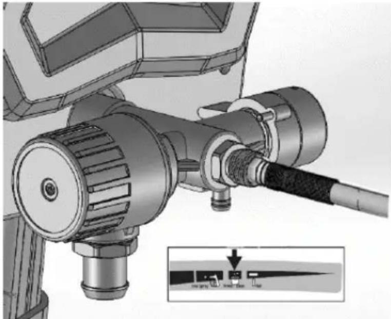
natural_image
Technical illustration of a mechanical device with a cable and adjustment knob, showing no text or symbols.h) Drej Prime/Spray-ventilen ned til PRIME-position:

natural_image
Mechanical assembly diagram showing a valve mechanism with a black curved arrow indicating rotational direction (no text or symbols present)i) Drej ON/OFF-kontakten til positionen on ("I").
natural_image
Technical line drawing of a spray gun assembly with two components (no text or symbols)c) Drej Prime/Spray-ventilen ned til PRIME-position:
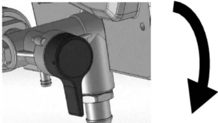
natural_image
Mechanical component with pipe connection and directional arrow (no text or symbols)d) Drej ON/OFF-kontakten til positionen on ("I").
natural_image
Mechanical component diagram showing a lever mechanism with an upward arrow indicator (no text or symbols present)natural_image
Illustration of a hand holding a cable or plug, with no visible text or symbols3.4.5 Statisk jordforbindelse (oliebaseret maling)
natural_image
Mechanical assembly diagram showing a disassembled component with bolts and a spherical part (no text or symbols)natural_image
Illustration of a mechanical component with three parts, one being cut and others emerging (no text or symbols)
natural_image
Line drawing of a mechanical pump or cart with wheels and a handle, labeled 'R' (no text or symbols on the diagram itself)

natural_image
Coiled wire with two small rectangular components, labeled 'N' at the end (no other text or symbols)natural_image
Mechanical assembly diagram showing a valve and connecting rod (no text or symbols)natural_image
Illustration of a robotic arm with articulated joints and control panel (no text or symbols)natural_image
Illustration of a robotic device with a lock icon and directional arrow (no text or symbols)natural_image
Two-step diagram showing hand operating a camera setup with tool, no text or symbols presentnatural_image
Technical illustration of a mechanical device with a close-up inset showing a labeled component (no text or symbols present)natural_image
Two-step illustration showing hand operating a camera setup with tool, no text or symbols presentnatural_image
Illustration of a bucket pouring liquid into a container, and a close-up of a textured material inside a bucket (no text or symbols)3.3.3 Paineenpoisto
natural_image
Close-up of a black electrical switch with a circular indicator light on the side panel (no readable text or symbols)natural_image
Technical illustration of mechanical components with lock and washer symbols (no text or labels)natural_image
Mechanical assembly diagram showing a motor and cable with a close-up inset of a control panel (no text or symbols visible)natural_image
Mechanical assembly diagram showing pipe connection and directional arrow (no text or symbols)natural_image
Illustration of a hand using a tool to lift a cylindrical component, with an upward arrow indicating motion (no text or symbols)natural_image
Illustration of three cylindrical cans with embedded electrical components and a star-shaped object (no text or symbols)natural_image
Mechanical assembly diagram showing a shaft and housing with a curved arrow indicating rotation (no text or symbols present)natural_image
Mechanical assembly diagram showing a motor connected to a cable with a close-up inset illustrating the internal components (no text or symbols present)natural_image
Close-up of a black square button with white letter 'I' and 'O' on a metal panel (no readable text or symbols beyond basic markings)natural_image
Illustration of three paint cans with different internal components, including a star-shaped device and a warning light (no text or symbols)natural_image
Illustration of a mechanical device with exploded view and close-up views (no text or symbols)natural_image
Illustration of a handheld device with internal components and a hand holding a tool, showing motion direction (no text or symbols)natural_image
Mechanical device with a downward arrow indicating compression or disassembly (no text or symbols present)natural_image
Two-step illustration showing a hand using a tool to adjust the camera and press device (no text or symbols present)(207 bar, 20.7 MPa)
Low Spray
Prime / Clean
Roll
(103 bar, 10.3 MPa)
(34.5 bar, 3.5 MPa)
natural_image
Illustration of a hand using a tool to cut a rectangular object, with an arrow indicating the process (no text or symbols present)natural_image
Two-step diagram showing hand operating a camera setup with tool, no text or symbols presentnatural_image
Diagram showing a pipe connection with a directional arrow indicating movement (no text or symbols present)natural_image
Illustration of three metallic cans with paint dripping, connected by a ladder and a star-shaped object (no text or symbols)natural_image
Technical illustration of a mechanical device with attached cable and connector (no text or symbols visible)natural_image
Mechanical assembly diagram showing a valve mechanism with a black curved arrow indicating rotational direction (no text or symbols present)natural_image
Technical line drawing of a mechanical device with tripod and cylindrical components (no text or symbols)natural_image
Illustration of a metallic basin with a curved pipe inserted into the water (no text or symbols)natural_image
Illustration of a laboratory apparatus with a container and tubing (no text or symbols)natural_image
Illustration of a mechanical device with a lock icon and directional arrow, no text or symbols present.natural_image
Mechanical component with a curved arrow indicating rotational direction (no text or symbols present)natural_image
Mechanical component with a curved arrow indicating rotation or direction (no text or symbols present)natural_image
Illustration of a medical or laboratory procedure showing a tool inserted into a device (no text or symbols visible)natural_image
Mechanical assembly diagram showing a mechanical component with bolts and a ball, no visible text or symbolsnatural_image
Illustration of a mechanical component with three parts emerging from it, showing different angles and shapes (no text or symbols)
natural_image
Line drawing of a mechanical pump or cart with wheels and a handle, labeled 'R' (no text or symbols on the diagram itself)

natural_image
Coiled wire with two small rectangular components, labeled 'N' at the end (no other text or symbols)PLAATS VAN HET APPARAAT
natural_image
Two industrial electric spray machines with hoses and wheels, shown from different angles (no visible text or labels)natural_image
Mechanical assembly diagram showing a valve and connecting rod (no text or symbols)natural_image
Mechanical assembly diagram showing a robotic arm and articulated joints (no text or labels)e) Activeer de trekkervergrendeling:
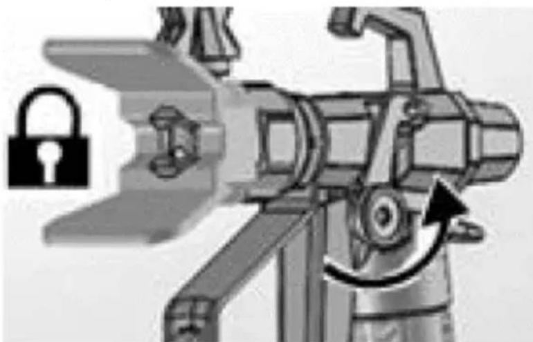
natural_image
Illustration of a robotic device with a lock icon and directional arrow (no text or symbols)natural_image
Two-step diagram showing hand operating a camera setup with tool, no text or symbols presentnatural_image
Technical illustration of a mechanical device with a cable and adjustment knob, showing no text or symbols.natural_image
Illustration of a bucket pouring liquid into a container, with a close-up of the container containing a textured substance (no text or symbols)3.3.3 Drukontlasting
natural_image
Close-up of a black electrical switch with a circular button, mounted on a wall (no visible text or symbols)natural_image
Technical illustration of mechanical components with lock and washer symbols (no text or labels)natural_image
Mechanical assembly diagram showing a motor and cable with a close-up inset of the component (no text or symbols visible)natural_image
Mechanical assembly diagram showing a valve mechanism with a black curved arrow indicating rotation or direction (no text or symbols present)natural_image
Illustration of a hand using a tool to lift a cylindrical component, with an upward arrow indicating motion (no text or symbols)f) Schakel de trekkervergrendeling in.
natural_image
Illustration of three metallic cans with embedded icons and a star-shaped object in the background (no text or symbols)natural_image
Mechanical assembly diagram showing pipe connection and rotation arrow (no text or symbols)natural_image
Mechanical assembly diagram showing a motor and cable connector with a close-up inset of a labeled component (no text or symbols present)natural_image
Close-up of a black square button with the number '1' and letter 'O' on its side, mounted on a metal panel (no additional text or symbols visible)natural_image
Illustration of three cans with different designs and a central device (no text or symbols visible)natural_image
Illustration of three different types of mechanical devices with no visible text or symbolsnatural_image
Illustration of a hand tool and its internal components, showing a disassembly or assembly process (no text or symbols present)natural_image
Illustration of a mechanical device with a downward arrow indicating compression or disassembly (no text or symbols present)natural_image
Two-step illustration showing a hand using a tripod to adjust the camera and press device (no text or symbols present)natural_image
Illustration of a hand using a tool to cut a rectangular object, with an arrow indicating the process (no text or symbols present)natural_image
Two-step diagram showing hand operating a camera setup with tripod and tripod stand (no text or symbols)natural_image
Diagram showing a pipe connection with a directional arrow indicating movement (no text or symbols present)natural_image
Illustration of three metallic cans with embedded icons and a stylized object, no text or symbols present.natural_image
Technical illustration of a mechanical device with attached cable and connector (no text or symbols visible)natural_image
Mechanical assembly diagram showing a valve mechanism with a black curved arrow indicating rotational direction (no text or symbols present)natural_image
Technical line drawing of a spray gun assembly with two components (no text or symbols)natural_image
Illustration of a metallic pipe fitting with a curved handle, partially submerged in liquid (no text or symbols)natural_image
Diagram of a laboratory apparatus with a container and tubing, no visible text or symbolsd) Activeer de trekkervergrendeling.
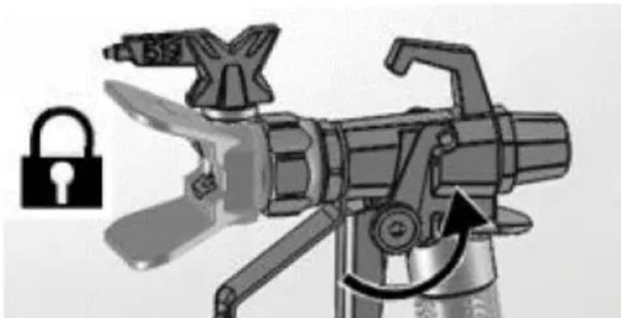
natural_image
Illustration of a mechanical device with a lock icon and directional arrow, no text or symbols present.natural_image
Mechanical component with pipe connection and directional arrow (no text or symbols)natural_image
Mechanical assembly diagram showing a disassembled component with a spherical part inserted, no visible text or symbolsnatural_image
Illustration of a mechanical component with three parts, one emitting a ring and the other falling into a sphere (no text or symbols)
natural_image
Line drawing of a mechanical pump or cart with wheels and a handle, labeled 'R' (no text or symbols on the diagram itself)

natural_image
Coiled wire with two small rectangular components, labeled 'N' at the end (no other text or symbols)natural_image
Two industrial pressure sprayer machines with hoses and wheels, shown from different angles (no text or symbols visible)natural_image
Mechanical assembly diagram showing a valve and connecting rod (no text or symbols)natural_image
Illustration of a robotic arm with articulated joints and control panel (no text or symbols)natural_image
Illustration of a robotic arm with a padlock symbol and an arrow indicating rotation (no text or labels)f) Fjern spissbeskyttelsen. Vær forsiktig siden spisspakningen kan falle ut när spissbeskyttelsen fjernes:
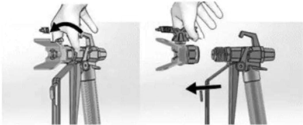
natural_image
Two-step diagram showing hand operating a camera setup with tool, no text or symbols presentnatural_image
Technical illustration of a mechanical device with attached cable and motor assembly (no text or symbols)natural_image
Illustration of a bucket pouring liquid into a container, and a close-up of a textured material inside a bucket (no text or symbols)3.3.3 Trykkavlastning
natural_image
Close-up of a black rectangular electronic switch with a circular button, mounted on a wall (no visible text or symbols)b) Aktiver avtrekkerlåsen. Det anbefales alltid å koble den inn när maskinen er stoppet, for å forhindre at pistolen utløses ved et uhell:
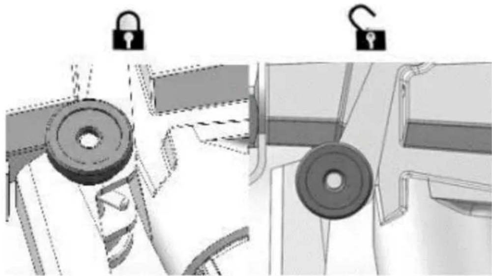
natural_image
Technical illustration of mechanical components with lock and washer symbols (no text or labels)natural_image
Mechanical device with attached cable and mechanical components, showing a close-up inset of a control panel (no text or symbols visible)natural_image
Mechanical assembly diagram showing pipe connection and directional arrow (no text or symbols)natural_image
Illustration of a hand using a tool to lift a cylindrical component, with an upward arrow indicating motion (no text or symbols)f) Aktiver avtrekkerlåsen.
g) Hvis du mistenker at sprøytedysen eller slangen er tilstoppet eller at trykket ikke er helt lettet, enn:
- Løsne tuppbeskytterens holdemutter eller slangeendekoblingen veldig sakte for å avlaste trykket gradvis.
• Løsne mutteren eller koblingen helt.
• Fjern den luftfrie slangen eller spraytuppen.
natural_image
Illustration of three cylindrical cans with embedded electrical components and a star-shaped object (no text or symbols)natural_image
Mechanical assembly diagram showing a shaft and housing with a curved arrow indicating rotation (no text or symbols present)natural_image
Mechanical assembly diagram showing a motor connected to a cable with a close-up inset illustrating the internal components (no text or symbols present)natural_image
Close-up of a black square button with white letter 'I' and 'O' on a metal panel (no readable text or symbols beyond basic markings)natural_image
Illustration of three paint cans with different internal components, including a star-shaped device and a battery (no text or symbols)natural_image
Illustration of a mechanical device with exploded view and close-up views (no text or symbols)natural_image
Illustration of a hand tool and its internal components, showing a disassembly process (no text or symbols)natural_image
Illustration of a mechanical device with a downward arrow indicating compression or disassembly (no text or symbols present)natural_image
Two-step illustration showing hand tool application on a tripod, with no visible text or symbols- Hold pistolen 30 cm fra overflaten og sikt rett mot overflaten (v). Å vippe pistolen til rett sprøytevinkel forårsaker ujevn maling (X).
- Bøy håndleddet for å holde pistolen rett (v). Å vifte pistolen til direkte spray i en vinkel forårsaker en ujevn finish (X).
3.3.10 Utløser pistolen
natural_image
Two-step diagram showing hand tool application on a tripod, with no visible text or symbolsc) Løft sugerøret og dreneringsrøret fra malingsspann. La malingen renne ned i spannet.
d) Skille avløpsrøret (mindre) fra sugerøret (større):
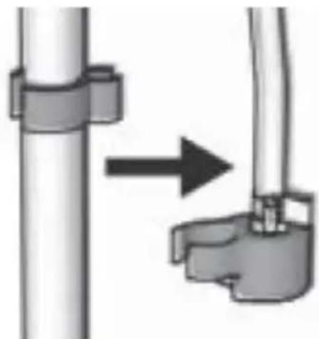
natural_image
Diagram showing a pipe connection with a directional arrow indicating movement (no text or symbols present)e) Plasser tomme avfalls- og spylevæskespann side ved side.
f) Plasser sugerøret i spylevæske. Bruk vann til vannbasert maling og mineralsprit eller kompatibelt oljebasert spylemiddel for oljebasert maling. Plasser avløpsrøret i avfallsbeholder:
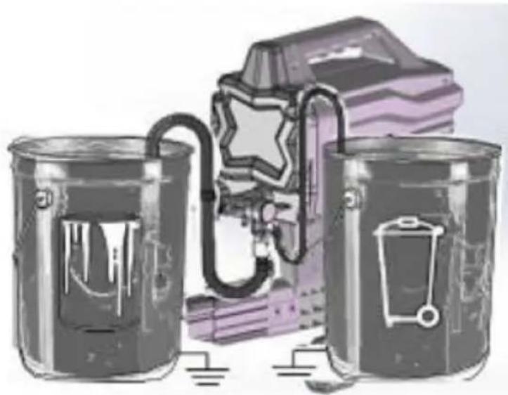
natural_image
Illustration of three cans with paint dripping, next to a stylized backpack and lock mechanism (no text or symbols)natural_image
Technical illustration of a mechanical device with a cable and adjustment knob, showing no text or symbols.h) Drei Prime/Spray-ventilen ned til PRIME-posisjon:
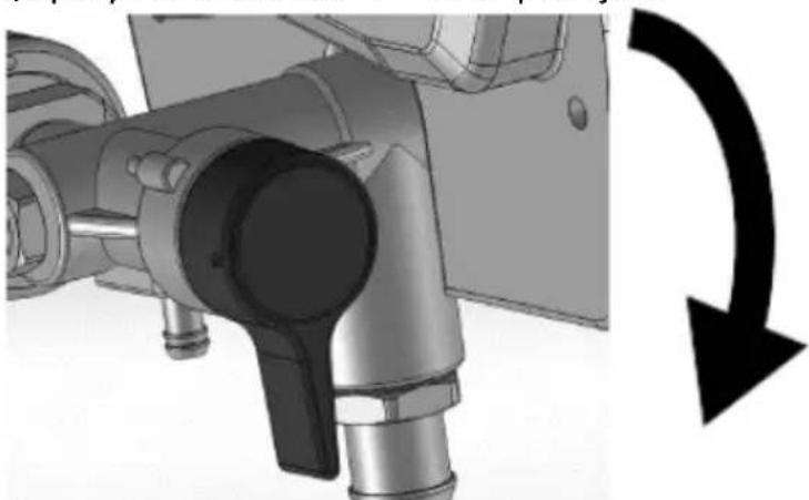
natural_image
Mechanical assembly diagram showing a rotating component with a curved arrow indicating rotational motion (no text or symbols present)natural_image
Technical line drawing of a spray gun assembly with two components (no text or symbols)flowchart
graph TD
    A["Feed Fuel"] --> B["Valve Installation"]
    B --> C["Recycle to Bottle"]
    C --> D["Recycle to Tank"]
    D --> E["Final Collection"]
c) Tørk maling av utsiden av pistolen med en myk klut fuktet med vann eller skyllevæske.
3.4.3 Korttidslagring
natural_image
Illustration of a metallic pipe fitting with a curved handle, partially submerged in liquid (no text or symbols)c) Dekk maling og spann tett med plastfolie:
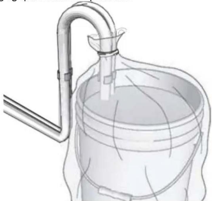
natural_image
Diagram of a laboratory apparatus with a container and tubing, no visible text or symbolsnatural_image
Illustration of a mechanical device with a lock icon and directional arrow, no text or symbols present.natural_image
Mechanical component with pipe fittings and a black circular arrow indicating rotation (no text or symbols)natural_image
Mechanical component diagram showing a lever mechanism with an upward arrow indicator (no text or symbols present)h) La pistolen være festet til slangen.
i) Fjern spissen og beskyttelsen og rengjør med vann eller skyllevæske og en børste.
j) Tørk maling av utsiden av pistolen med en myk klut fuktet med vann eller skyllevæske.
k) Fest en plastpose rundt suge- og dreneringsrøret for å fange opp eventuelle drypp:
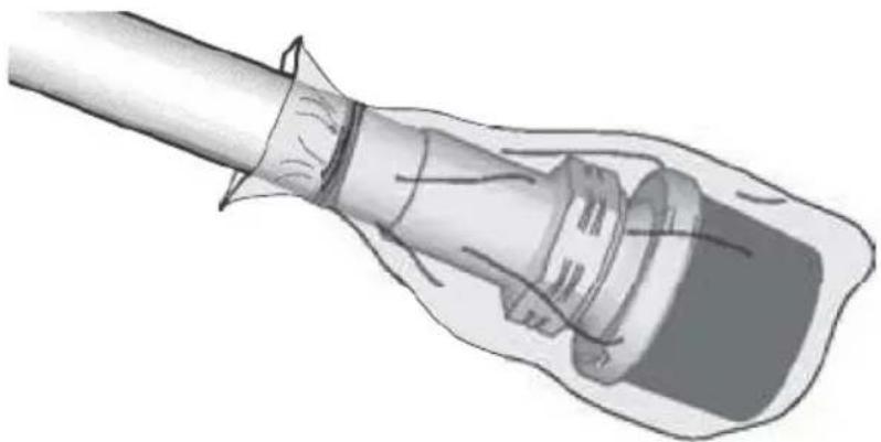
natural_image
Illustration of a hand holding a cable or plug, with no visible text or symbols3.4.5 Statisk jording (oljebasert maling)
- Bruk alltid et metallspann for oljebaserte materialer som krever spyling med kompatible oljebaserte spyleløsninger när sprøyten er spylt eller trykket avlastes.
- Bruk kun ledende metallspann, plassert på en jordet overflate som betong.
- Ikke plasser spann på en ikke-ledende overflate som papir eller papp som avbryter jordingskontinuiteten.
natural_image
Mechanical assembly diagram showing a mechanical component with a ball and threaded fitting (no text or symbols)natural_image
Illustration of a mechanical component with three parts, showing a light bulb, a spring, and a ball (no text or symbols)A. Fyll/sprayventil
B. Tryckkontrollratt
C. På / Av knapp
D. Sugrör
E. Avloppsrör
F. Spraypistol
APPARATENS PLACERING
natural_image
Mechanical assembly diagram showing a tool interacting with a mechanical component (no text or symbols visible)natural_image
Illustration of a robotic arm with articulated joints and a control panel (no text or symbols)natural_image
Illustration of a robotic arm with a padlock symbol and an arrow indicating rotation (no text or symbols present)natural_image
Two-step diagram showing hand operating a camera setup with tool, no text or symbols presentnatural_image
Technical illustration of a mechanical device with a cable and adjustment knob (no text or symbols)natural_image
Illustration of a bucket pouring liquid into a container, and a close-up of a textured material inside a container (no text or symbols)natural_image
Close-up of a black electrical switch with a circular button, mounted on a wall (no visible text or symbols)natural_image
Technical illustration of mechanical components with lock and washer symbols (no text or labels)natural_image
Mechanical assembly diagram showing a motor and cable with a close-up inset of a control panel (no text or symbols visible)natural_image
Mechanical assembly diagram showing a valve mechanism with a black curved arrow indicating rotation (no text or symbols present)natural_image
Illustration of a hand using a tool to lift a cylindrical component, with an upward arrow indicating motion (no text or symbols)natural_image
Illustration of three cylindrical containers with embedded electrical components and a star symbol on the middle (no text or symbols present)f) Vrid Prime/Spray-ventilen ner till PRIME-läge:
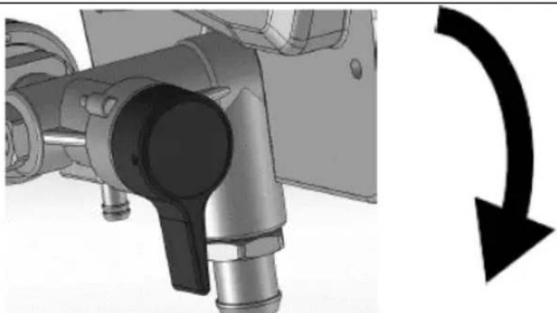
natural_image
Mechanical assembly diagram showing pipe connection and rotation arrow (no text or symbols)natural_image
Mechanical device with attached cable and mechanical components, showing a close-up inset of a labeled component (no readable text or symbols)natural_image
Close-up of a black square button with the number '1' and letter 'O' on its surface, mounted on a metal panel (no additional text or symbols visible)natural_image
Illustration of three cans with various symbols and colors, including a star-shaped object and a warning sign (no text or labels present)natural_image
Illustration of three different mechanical devices with no visible text or symbolsnatural_image
Illustration of a handheld device with internal components and a hand holding a power tool (no text or symbols)natural_image
Mechanical device with a downward arrow indicating compression or disassembly (no text or symbols visible)natural_image
Two-step diagram showing hand operating a camera setup with tool, no text or symbols present3.3.11 Riktar pistolen
natural_image
Illustration of a hand using a tool to adjust or install a component, with an arrow indicating direction (no text or symbols present)3.3.12 Spraymönsterkvalitet
natural_image
Two-step illustration showing hand tool application on a tripod, with no visible text or symbolsnatural_image
Diagram showing a pipe connection with a directional arrow indicating movement (no text or symbols present)natural_image
Illustration of three metallic cans with paint dripping, next to a stylized book and pen (no text or symbols)natural_image
Technical illustration of a mechanical device with a cable and adjustment knob, showing no text or symbols.h) Vrid Prime/Spray-ventilen ner till PRIME-läge:

natural_image
Mechanical assembly diagram showing a rotating component with a curved arrow indicating rotational motion (no text or symbols present)natural_image
Technical line drawing of a spray gun assembly with two components (no text or symbols)flowchart
graph TD
    A["Feed Fuel"] --> B["Recycle"]
    B --> C["Heating"]
    C --> D["Product"]
natural_image
Illustration of a metallic pipe fitting with a curved handle, partially submerged in liquid (no text or symbols)natural_image
Diagram of a laboratory apparatus with a container and tubing, no visible text or symbolsd) Aktivera avtryckarlåset.

natural_image
Illustration of a mechanical device with a lock icon and directional arrow, no text or symbols present.c) Vrid Prime/Spray-ventilen ner till PRIME-läge:
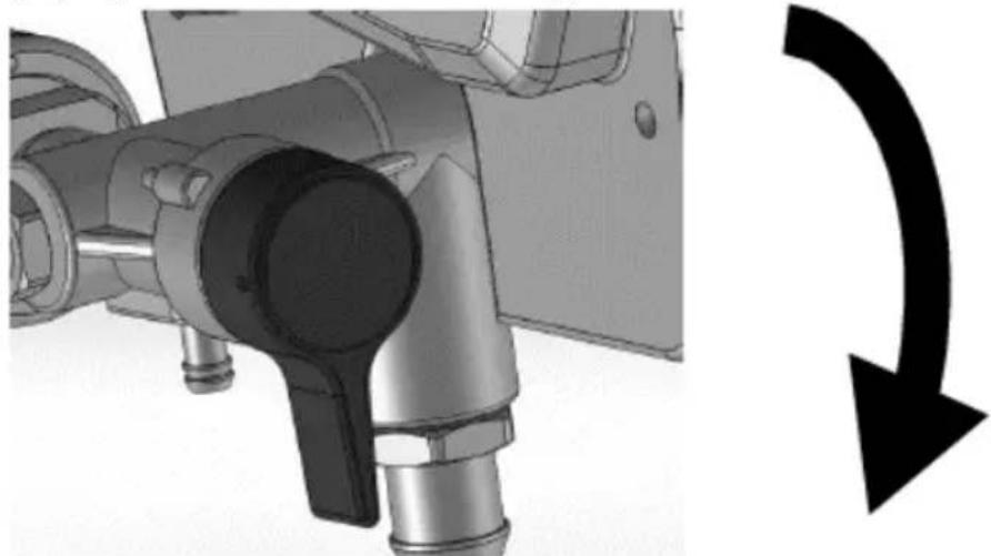
natural_image
Mechanical component with pipe connection and curved arrow symbol (no text or labels)natural_image
Mechanical component with a curved arrow indicating rotation or direction (no text or symbols present)natural_image
Illustration of a medical or laboratory procedure showing a tool inserted into a device (no text or symbols present)natural_image
Mechanical assembly diagram showing a mechanical component with bolts and a ball, no visible text or symbolsnatural_image
Illustration of a mechanical component with three parts, showing a tip and two others falling (no text or symbols)natural_image
Mechanical assembly diagram showing a cam or probe inserted into a housing with a tool handle (no text or symbols visible)natural_image
Mechanical assembly diagram showing a robotic arm and articulated joints (no text or labels)natural_image
Illustration of a robotic device with a lock icon and directional arrow (no text or symbols)natural_image
Two-step diagram showing hand operating a camera setup with tool, no text or symbols presentnatural_image
Technical illustration of a mechanical device with a cable and adjustment knob (no text or symbols)natural_image
Illustration of a bucket pouring liquid into a container with a lid, alongside a close-up of the interior of a water-filled container (no text or symbols)natural_image
Close-up of a black electrical switch with a circular indicator light on the side panel (no text or symbols visible)natural_image
Technical illustration of mechanical components with lock and washer symbols (no text or labels)natural_image
Technical illustration of a mechanical device with a cable and adjustment knob, showing no text or symbols.natural_image
Mechanical assembly diagram showing pipe connection and directional arrow (no text or symbols)natural_image
Illustration of a hand using a tool to lift a cylindrical component, with an upward arrow indicating motion (no text or symbols)natural_image
Illustration of three metallic cans with embedded electrical components and a star symbol (no text or symbols present)natural_image
Mechanical component with a curved arrow indicating rotational direction (no text or symbols present)natural_image
Illustration of three cylindrical containers with embedded electrical components and a star symbol (no text or symbols present)natural_image
Illustration of three different types of mechanical devices with no visible text or symbolsnatural_image
Illustration of a handheld device with internal components and a hand tool, showing no text or symbols.natural_image
Mechanical device with a downward arrow indicating compression or disassembly (no text or symbols present)natural_image
Two-step diagram showing hand operating a camera setup with tool, no text or symbols present3.3.11 Apontando a arma
natural_image
Illustration of a hand using a tool to cut a rectangular object, with an arrow indicating the process (no text or symbols present)natural_image
Diagram showing a pipe connection with a directional arrow indicating movement (no text or symbols present)natural_image
Illustration of three cans with paint dripping, next to a stylized book and lock mechanism (no text or symbols)natural_image
Technical illustration of a mechanical device with attached tubing and a close-up inset showing internal components (no text or symbols)natural_image
Mechanical assembly diagram showing a rotating component with a curved arrow indicating rotational motion (no text or symbols present)natural_image
Technical line drawing of a spray gun assembly with two components (no text or symbols)flowchart
graph TD
    A["Feed Fuel"] --> B["Valve Installation"]
    B --> C["Recycle to Bottle"]
    C --> D["Recycle to Tank"]
    D --> E["Final Collection"]
natural_image
Illustration of a metallic pipe fitting with a curved handle, partially submerged in liquid (no text or symbols)natural_image
Diagram of a laboratory apparatus with a container and tubing, no visible text or symbolsnatural_image
Illustration of a mechanical device with a lock icon and directional arrow, no text or symbols present.e) Deixe a pistola presa à mangueira.
natural_image
Mechanical component diagram showing a valve assembly with a curved arrow indicating rotation (no text or symbols present)natural_image
Mechanical component with a curved arrow indicating rotation or direction (no text or symbols present)h) Deixe a arma presa à mangueira.
natural_image
Illustration of a plug inserted into a socket (no text or symbols present)3.4.5 Aterramento estático (tintas à base de óleo)
natural_image
Mechanical assembly diagram showing a mechanical component with a ball and threaded fitting (no text or symbols)natural_image
Illustration of a mechanical component with three parts, one emitting a ring and the other falling into a sphere (no text or symbols)natural_image
Two industrial water purifier machines with hoses and wheels, shown from different angles (no text or symbols visible)b) Pripojte bezvzduchovú hadicu k výstupu kvapaliny. Pomocou klúča ich bezpečne dotiahnite:

natural_image
Mechanical assembly diagram showing a valve and connecting rod (no text or symbols)c) Pripojte druhý koniec hadice k striekacej pištoli.
natural_image
Mechanical assembly diagram showing a robotic arm and articulated joints (no text or labels)e) Zapnite zámok spúšte:

natural_image
Illustration of a robotic device with a lock icon and directional arrow (no text or symbols)natural_image
Two-step diagram showing hand operating a camera setup with tool, no text or symbols presentnatural_image
Technical illustration of a mechanical device with a close-up inset showing a labeled component (no text or symbols present)natural_image
Illustration of a bucket pouring liquid into a container, and a close-up of a textured surface inside a bucket (no text or symbols)natural_image
Close-up of a black electrical switch with a circular button, mounted on a metal door (no visible text or symbols)natural_image
Mechanical assembly diagram showing pipe connection and directional arrow (no text or symbols)natural_image
Illustration of a hand using a tool to lift a cylindrical component, with an upward arrow indicating motion (no text or symbols)f) Zapnite zámok spúšte.
natural_image
Illustration of three metallic cans with embedded electrical components and a star symbol (no text or symbols present)f) Otočte plniaci/striekací ventil nadol do polohy PRIME:

natural_image
Mechanical assembly diagram showing a valve mechanism with a black curved arrow indicating rotational direction (no text or symbols present)natural_image
Mechanical assembly diagram showing a motor and cable connector with a close-up inset of a labeled component (no text or symbols present)natural_image
Close-up of a black square button with white letter 'I' and 'O' on a metal panel (no additional text or symbols)natural_image
Illustration of three paint cans with different internal components, including a star-shaped device and a warning light (no text or symbols)natural_image
Illustration of three different types of mechanical devices with no visible text or symbols3.3.11 Mierenie pištole
natural_image
Illustration of a hand using a tool to cut a rectangular object, with an arrow indicating the process (no text or symbols present)natural_image
Diagram showing a pipe connection with a directional arrow indicating movement (no text or symbols present)natural_image
Illustration of two cans with paint dripping, connected by a ladder to a stylized backpack and battery (no text or symbols)natural_image
Technical illustration of a mechanical device with attached cable and connector (no text or symbols)h) Otočte plniaci/striekací ventil nadol do polohy PRIME:
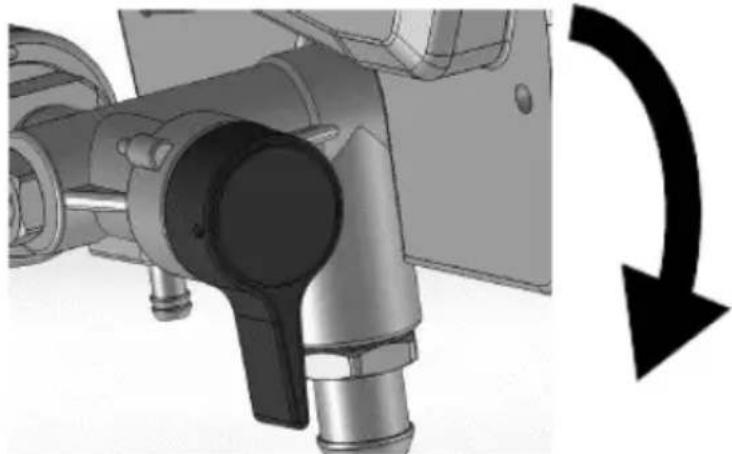
natural_image
Mechanical assembly diagram showing a valve mechanism with a black curved arrow indicating rotational direction (no text or symbols present)n) Otočte ovládací gombík tlaku na najnižšiu hodnotu.
o) Prestaňte spúšťať pištol'. Zapnite zámok spúšte.
p) Otočte plniaci/striekací ventil nadol do polohy PRIME.
q) Prepínač ON/OFF prepnite do polohy vypnuté („O“).
3.4.2 Čistenie pištole
natural_image
Technical line drawing of a spray gun assembly with two components (no text or symbols)b) Odstráňte striekaciu špičku a chránič špičky a vyčistite vodou alebo preplachovacou kvapalinou a kefou.

flowchart
graph TD
    A["Feed Fuel"] --> B["Valve Installation"]
    B --> C["Recycle to Bottle"]
    C --> D["Recycle to Tank"]
    D --> E["Final Collection"]
c) Utrite farbu z vonkajšej strany pištole mäkkou handričkou navlhčenou vodou alebo preplachovacou kvapalinou.
3.4.3 Krátkodobé skladovanie
natural_image
Illustration of a metallic faucet with a curved handle and central shaft, partially submerged in liquid (no text or symbols)natural_image
Diagram of a laboratory apparatus with a container and tubing, no visible text or symbolsnatural_image
Illustration of a camera with a lock icon and directional arrow, no text or symbols presentnatural_image
Mechanical component diagram showing a lever mechanism with an upward arrow indicator (no text or symbols present)natural_image
Illustration of a hand holding a medical device with a bulbous cap (no text or symbols)natural_image
Mechanical assembly diagram showing a disassembled component with bolts and a ball (no text or symbols)natural_image
Exploded view diagram of a mechanical component showing disassembled parts (no text or symbols)3.4.7 Kompatibilita čistiacich kvapalín
For the disposal of the device please consider and act according to the national and local rules and regulations.
CONTACT
expondo Polska sp. z o.o. sp. k.