ES-1010 - Paint spray MSW - Free user manual and instructions
Find the device manual for free ES-1010 MSW in PDF.

| Product type | Electric paint sprayer |
| Model | MSW-ES-1010 |
| Supply voltage | 230 V~ / 50 Hz |
| Rated power | 1010 W |
| Protection class | II (double insulation) |
| IP protection rating | IPX0 |
| Dimensions (W × D × H) | 295 × 335 × 371 mm |
| Weight | 8.2 kg |
| Size of included nozzles | 415, 515, 517 (supplied with 515: angle 50°, diameter 0.015 mm) |
| Maximum working pressure | 227 bar / 22.7 MPa / 3292 PSI |
| Maximum flow rate (spraying) | 1.5 L/min |
| Suction hose (diameter × length) | ∅ 16.5 mm × 920 mm |
| Return hose (diameter × length) | ∅ 5 or 6.6 mm × 850 mm |
| Extension | 500 mm |
| Sound power level LwA | 93.6 dB(A) (guaranteed 110 dB(A)) |
| Sound pressure level LpA | 84.7 dB(A) |
| Vibration emission (handle) | 1.215 m/s² (uncertainty K = 1.5 m/s²) |
| Intended use | Spray painting on large interior/exterior surfaces |
| Compatible materials | Latex paints, petroleum-based (thinnable), varnishes |
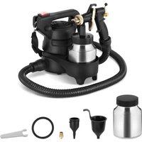
| Included items | Gun, HP hose, suction/return hose, nozzles, extension, TSL oil, keys, pressure gauge, support |
| Recommended safety equipment | Goggles, hearing protection, dust mask, gloves, overalls |
| Maintenance | Clean after each use; rinse with soapy hot water or mineral spirits; check filters |
| Warranty | Contact the manufacturer's after-sales service |
Frequently Asked Questions - ES-1010 MSW
User questions about ES-1010 MSW
0 question about this device. Answer the ones you know or ask your own.
Ask a new question about this device
Download the instructions for your Paint spray in PDF format for free! Find your manual ES-1010 - MSW and take your electronic device back in hand. On this page are published all the documents necessary for the use of your device. ES-1010 by MSW.
USER MANUAL ES-1010 MSW
natural_image
Close-up of a pressure gauge with metal fittings and tubing, no visible text or symbolsnatural_image
Close-up of a metallic connector with threaded end and red seal, attached to a black cylindrical device (no visible text or symbols)natural_image
Close-up of a metallic pump assembly with tubing and a blue valve, no visible text or symbolsnatural_image
Line drawing of a paintbrush and paint can with a tool, no text or symbols presentnatural_image
Close-up of a metallic pipe fitting with a hexagonal bolt and handle (no visible text or symbols)
natural_image
Close-up of a metallic spray gun handle with black and white adjustment knobs (no text or symbols visible)3.3.3 Druckablass
natural_image
Line drawing of a hand holding a cylindrical object with a pointed tip (no text or symbols)
natural_image
Technical line drawing of a mechanical component or tool assembly (no text or symbols)natural_image
Technical line drawing of a mechanical component or tool assembly (no visible text or symbols)natural_image
Top-down view of a black circular filter or mesh structure with visible internal structure and metal clips (no text or symbols)natural_image
Technical line drawings of mechanical components with directional arrows indicating movement (no text or symbols)natural_image
Line drawing of a mechanical device with a sword and lever (no text or symbols)natural_image
Diagram of a mechanical device with arrows indicating motion or force direction (no text or symbols)natural_image
Line drawing of a hand operating a portable air conditioner unit (no text or symbols)3.4.8 Reinigung des Ansaugventils
natural_image
Technical line drawing of a mechanical device with no visible text or symbolsnatural_image
Technical line drawing of a mechanical device with a cylindrical component inserted, showing no text or symbols.| Description of the parameter | Value of the parameter |
| Product name | ELECTRIC PAINT SPRAYER |
| Model | MSW-ES-1010 |
| Supply voltage [V~] / Frequency [Hz] | 230/50 |
| Rated power [W]. | 1010 |
| Safety class | II |
| IP code | IPX0 |
| Dimensions [Width x Depth x Height; mm] | 295 x 335 x 371 |
| Weight [kg] | 8.2 |
| Supported nozzle sizes | 415/515/517In the set: 515 (= spray angle 50°, nozzle diameter 0.015 mm) |
| Maximum spray pressure [bar/MPa/PSI] | 227/22.7/3292 |
| Maximum flow [L/min] | 1.5 (spray) |
| Dimensions of the suction pipe - diameter/length[mm] | ∅ 16.5 / 920 |
| Dimensions of the return pipe - diameter/length[mm] | ∅ 5 or 6.6 / 850 |
| End extension [mm] | 500 |
| Sound power level LWA / Measurement uncertainty K= [dB(A)] | 93.6 (guaranteed 110) / K = 3 |
| Sound pressure level LpA / Measurement uncertainty K= [dB(A)] | 84.7 / |
| Vibration emission level ah - main holder / output holder / Measurement uncertainty K= [m/s2] | 1.215 |
1. General Description
The instruction manual is intended to assist in safe and reliable use. The product is designed and manufactured strictly according to technical specifications using the latest technology and components and maintaining the highest quality standards.
PLEASE CAREFULLY READ AND UNDERSTAND THIS INSTRUCTION MANUAL BEFORE OPERATION,
To ensure long and reliable operation of the unit, make sure to operate and maintain it properly in accordance with the guidelines in this instruction manual. The technical data and specifications contained in this instruction manual are up to date. The manufacturer reserves the right to make changes in order to improve the quality. Taking the technical progress and the possibility of reducing noise into account, the unit is designed and built in such a way so that risks resulting from noise emissions are reduced to the lowest possible level.
Explanation of symbols
| CE | The product complies with applicable safety standards. |
 | Please read the instructions before use. |
 | Recyclable product. |
 | CAUTION! or WARNING! or REMINDER! describing a situation.(general warning sign). |
 | Wear ear protection. Exposure to noise may cause hearing loss. |
 | Wear protective goggles. |
 | Wear a dusk mask (protecting the respiratory tract). |
 | Wear protective gloves. |
 | Use respiratory protection. | |
 | Wear a protective suit. | |
 | CAUTION! Warning of electric shock! | |
 | CAUTION! Warning against loud noise! | |
 | CAUTION! Danger of fire - flammable material! | |
 | Warning against poisoning by toxic substances! | |
 | Safety class II equipment with double insulation. |
CAUTION! The illustrations in this instruction manual are for reference only and may differ from the actual product in some details.
The original instruction manual is in the German language version. Other language versions are translations from German.
2. Safety of use
CAUTION! Read all safety warnings and all instructions. Failure to follow the warnings and instructions may result in electric shock, fire and/or severe personal injury or death.
The term "unit" or "product" in the warnings and in the description of the instructions refers to the ELECTRIC PAINT SPRAYER.
2.1. Electrical safety
a) The plug of this unit must fit into the outlet. Do not modify the plug in any way. Original plugs and matching outlets reduce the risk of electric shock.
b) Avoid touching grounded parts, such as pipes, heaters, ovens, and refrigerators. There is an increased risk of electric shock if your body is grounded and touches the unit exposed to direct rain, wet pavement, and operation in a humid environment. If water enters the unit, there is an increased risk of damage to the unit and electric shock.
c) Do not touch the unit with wet or damp hands.
d) Do not use the cord in an unintended manner. Never use it to carry the unit or to pull the plug out of the socket. Keep the cord away from heat sources, oil, sharp edges or moving parts. Damaged or tangled cords increase the risk of electric shock.
e) When operating the unit outdoors, use an extension cord designed for outdoor use. Using an extension cord designed for outdoor use reduces the risk of electric shock.
f) Do not use the unit if the power cord is damaged or shows signs of wear. A damaged power cord should be replaced by a qualified electrician or the manufacturer's service department.
g) To avoid electric shock, do not immerse the cable, plug, or unit itself in water or other liquid. Do not use the unit on wet surfaces.
h) CAUTION - THREAT TO LIFE! When cleaning or using the unit, never immerse it in water or other liquids.
i) Do not use the unit in rooms with very high humidity / in the immediate vicinity of water tanks!
j) Do not allow the machine to get wet. Risk of electric shock!
2.2. Safety in the workplace
a) Keep the work area tidy and well lit. Disorder or poor lighting can lead to accidents. Be foresighted, watch what you are doing and use common sense when using the unit.
b) Do not use the unit in an explosive area, for example in the presence of flammable liquids, gases or dust. The unit produces sparks that can ignite dust or fumes.
c) If you have any doubts as to whether the unit is working properly or if it is damaged, contact the manufacturer's service department.
d) Only the manufacturer's service department can repair the unit. Do not carry out repairs yourself!
e) In case of open flames or fire, use only dry powder or snow (CO2) fire extinguishers to extinguish the live equipment.
f) No children or unauthorized persons are allowed in the work area. (Inattention may result in loss of control of the unit.)
g) Use the unit in a well-ventilated area.
h) Do not cut off the compressed air supply by crushing or kinking the pressure hoses.
i) Check the condition of the safety stickers regularly. Replace them if they are illegible.
j) Keep these instructions for use for future reference. If the unit is to be passed on to a third party, the operating instructions must also be handed over together with the unit.
k) Keep the packaging and small assembly parts out of the reach of children.
I) Keep the unit away from children and animals.
m) When using this unit together with other units, also follow the other instructions for use.

Please note! Keep children and other bystanders safe while operating the unit.
2.3. Personal safety
a) Do not operate this unit if you are tired, ill or under the influence of alcohol, drugs or medication that could impair your ability to operate the unit.
b) The unit may be operated by persons who are physically fit, capable of operating it and appropriately trained, and who have read this instruction manual and have been trained in occupational safety and health.
c) Use caution and common sense when operating this unit. A moment's inattention during operation may result in serious personal injury.
d) Use personal protective equipment as required when operating the unit as specified in Section 1 of the explanation of symbols. The use of appropriate, approved personal protective equipment reduces the risk of injury.
e) To prevent accidental start-up, make sure the switch is in the off position before connecting to a power source.
f) Do not overestimate your capabilities. Maintain body balance and equilibrium at all times during operation. This allows for better control of the machine in unexpected situations.
g) Do not wear loose clothing or jewelry. Keep hair, clothing, and gloves away from moving parts. Loose clothing, jewelry, or long hair can be caught in moving parts.
h) Eye, ear, and respiratory protection is recommended.
i) The unit is not a toy. Children should be watched to ensure that they do not play with the unit.
j) Pointing the gun at yourself, other people or animals is prohibited.
2.4. Safe use of the unit
a) Do not overload the unit. Use tools that are suitable for the application. A correctly selected unit will do a better and safer job for which it was designed.
b) Do not use the unit if the ON/OFF switch does not function properly (does not turn on and off). Units that cannot be controlled by the switch are unsafe, cannot operate, and must be repaired.
c) Unplug the unit before making adjustments, changing accessories, or putting it away. This precaution reduces the risk of accidental start-up.
d) Keep unused equipment out of the reach of children and out of the reach of anyone unfamiliar with the unit or this instruction manual. These units is dangerous in the hands of inexperienced users.
e) Keep the unit in good working condition. Check before each use for general damage or damage to moving parts (cracks in parts and components or any other condition that may affect the safe operation of the unit). If damaged, have the unit repaired before use.
f) Keep the unit out of the reach of children.
g) To ensure the designed operational integrity of the unit, do not remove factory-installed covers or loosen screws.
h) When transporting or moving the unit from storage to the place of use, observe the health and safety rules for manual handling applicable in the country where the unit is used.
i) Avoid situations in which the machine stops under heavy loads during operation. This can cause overheating of the drive elements and consequent damage to the equipment.
j) Do not leave the unit switched on unattended.
k) Clean the unit regularly to prevent permanent dirt build-up.
I) Do not process two workpieces at the same time.
m) Before each use, make sure that the nozzle is properly mounted in the machine and that the hose is properly attached and undamaged.
n) Do not carry or hang the unit by the pressure hose.
o) Do not obstruct the air inlet or outlet.
p) The unit is not a toy. Cleaning and maintenance must not be performed by children without adult supervision.
q) Do not tamper with the unit to alter its performance or design.
r) Keep the unit away from sources of fire and heat.
s) Do not overload the unit.
t) Do not block the ventilation openings of the unit!
u) Do not point the paint jet in the direction of air blowing/circulating sources.

CAUTION! Although the product has been designed to be safe, with adequate safeguards, and despite the additional safety features provided to the user, there is still a slight risk of accident or injury when handling the unit. You are advised to use caution and common sense when using this product.
3. Rules of use
The product is designed to spray paint on large surfaces or elements on the inside or outside and is intended to facilitate and speed up painting works e.g. in construction repair and finishing works.
CAUTION: The unit is not suitable for use with structural paints, primers or asphalt sealers!
The product is intended for home use only!
The user is responsible for any damage resulting from misuse.
3.1. Description
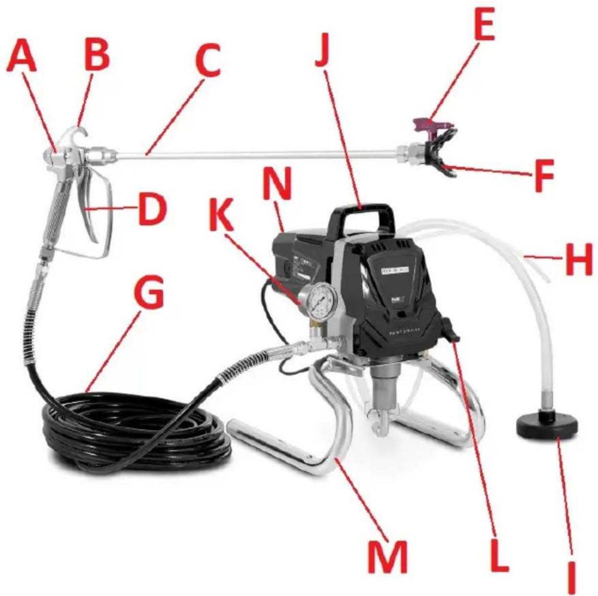
A. Spray gun
B. Gun grip
C. Extension tube
D. Trigger (with trigger lock)
E. Spray nozzle
F. Spray tip
G. Air hose (reinforced)
H. Material return hose
I. Suction hose with strainer
J. Transport handle
K. Manometer
L. Valve switch
M. Stand
N. ON/OFF switch (on the back of the unit)
3.2. Preparation for operation
POSITIONING OF THE UNIT
The ambient temperature must not exceed 45^ and ambient humidity should not exceed 85% . Use the unit in properly ventilated spaces. Do not block the air outlet of the unit. Keep the unit away from any hot surfaces. Always operate the unit on a level, stable, clean, fireproof and dry surface and out of the reach of children and persons of impaired mental, sensory and intellectual functions. Place the unit in such a way that the mains plug can be reached at any time. Ensure that the power supply to the unit corresponds to that specified on the identification plate!
ASSEMBLY OF THE UNIT
NOTE: Use the supplied wrenches to fasten the connections and tighten them securely together as the unit operates at very high pressure!
a) Screw the pressure gauge onto the outlet port.
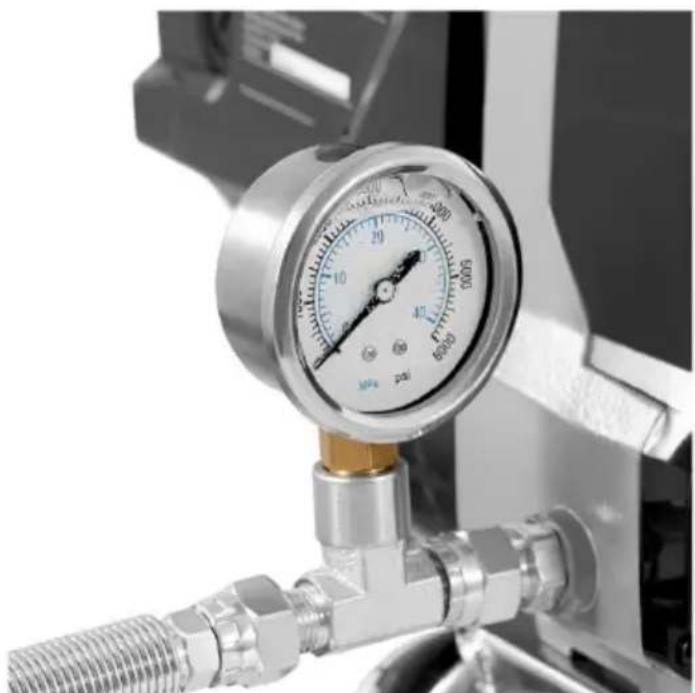
natural_image
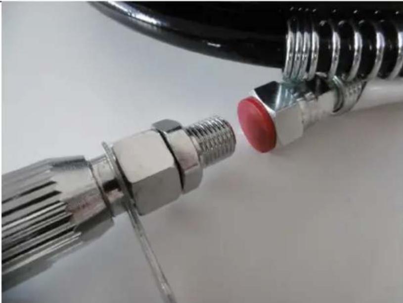
Close-up of a pressure gauge with metal fittings and tubing, no visible text or symbolsb) Screw the pneumatic hose (reinforced) to the end of the pressure gauge by first removing the plug from the end.
c) Screw the spray gun to the other end of the hose.
natural_image
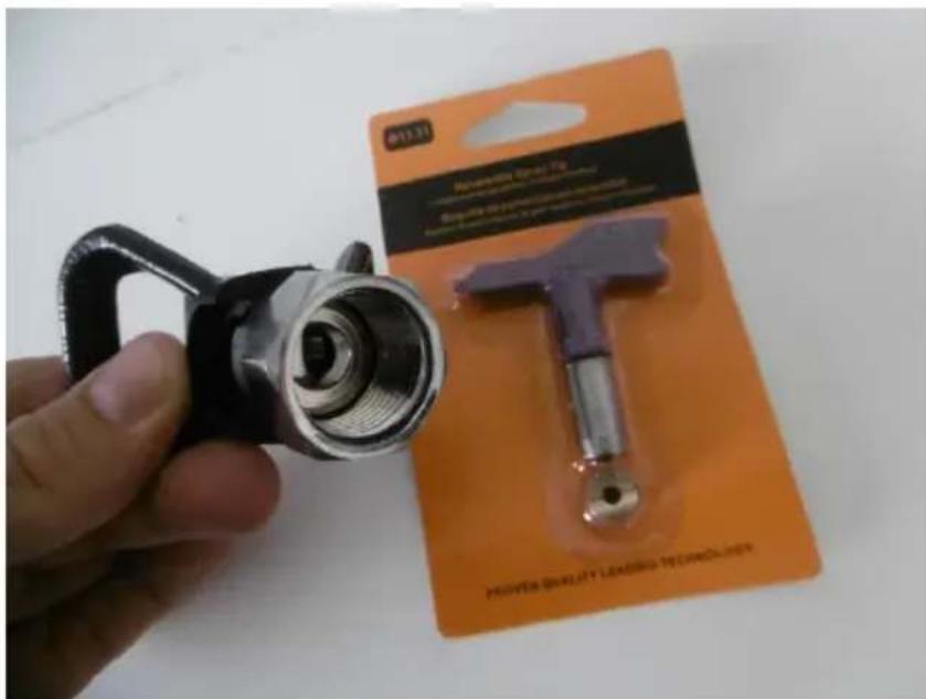
Close-up of metallic mechanical connectors with a red cap and threaded shaft, no visible text or symbolsd) Unscrew the nozzle from the spray gun and place the spray nozzle and its wrench on the inside of the spray gun according to the instructions on the back of the nozzle package. If the "aileron" of the nozzle key is pointing toward the outlet of the spray tip, it is the setting for painting, if it is pointing toward the gun, it is the setting for buildup.
IMPORTANT: do not attach the nozzle/spray tip until the hose and unit and hose have been cleaned and free of residual preservatives for storage - see details in the "Working with the unit" section.

e) If necessary, an extension can be attached between the spray gun and the spray tip. Remove the plugs from its ends and fit properly into the threads of the spray gun and spray tip.
f) Make sure that both the suction hose and the return hose are securely fastened to the unit outputs.
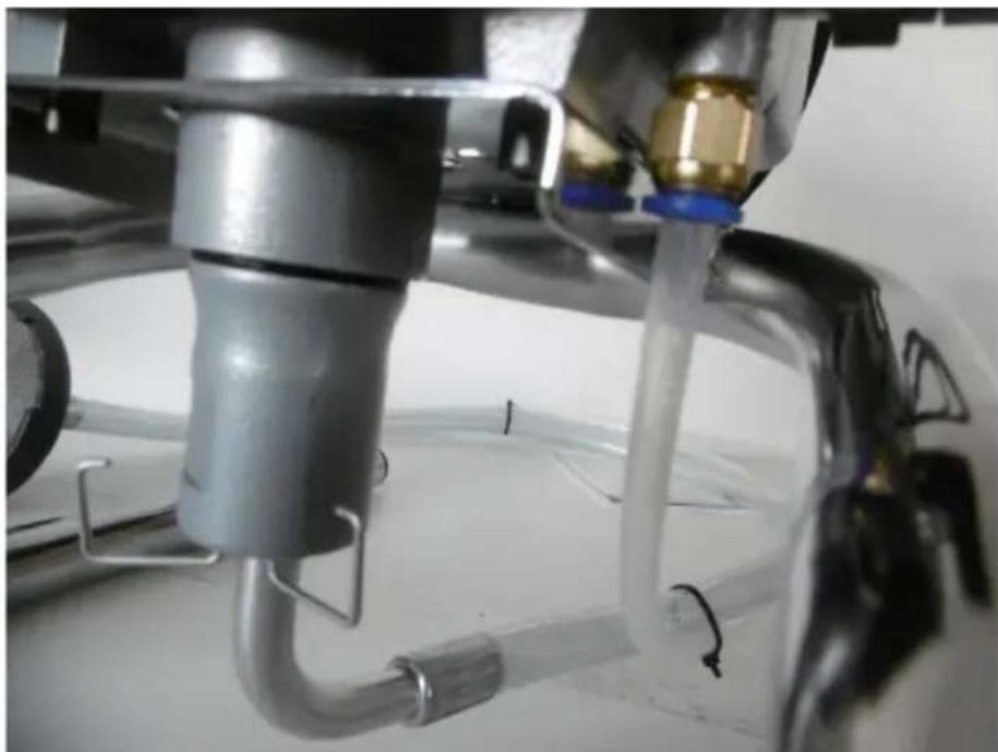
natural_image
Close-up of a laboratory setup with a metallic pump, tubing, and a transparent tubing with blue connectors (no visible text or symbols)g) Make sure that the ON/OFF switch is in the off ("O") position. Plug the unit's plug into an electrical outlet.
3.3. Working with the unit
3.3.1 Cleaning the inside of the unit (before first use)
IMPORTANT: each unit is factory-protected from the inside with a special fluid "TSL", which ensures its smooth operation and preserves it in case of risk of corrosion or prolonged storage.
a) The air hose and spray gun should be disconnected.
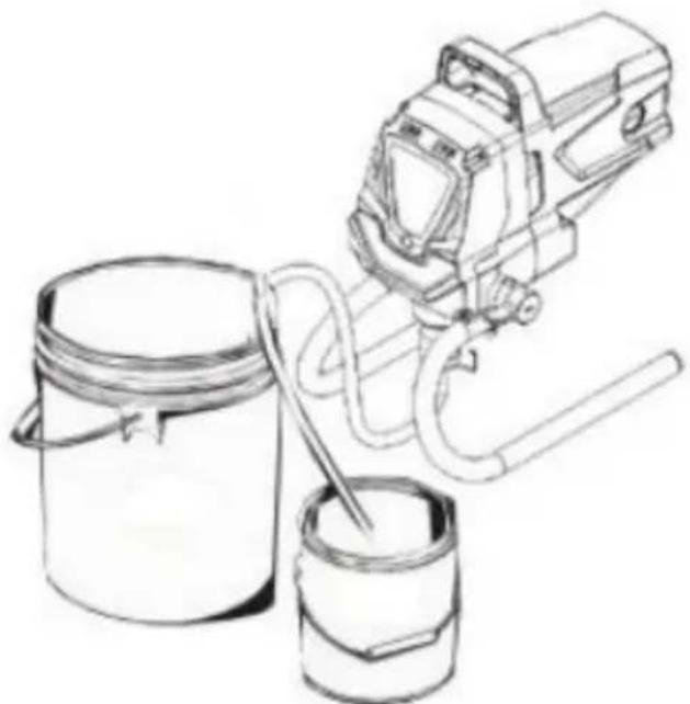
b) Place the suction hose in a container with material (e.g. paint) and the return hose in a container for residue (waste). Secure both hoses so that they do not accidentally fall out of the containers.
natural_image
Line drawing of a paintbrush and paint can with a brush, no text or symbols presentc) Set the valve switch to the "Air release/Clean" position.
d) Start the unit connected to power by moving the ON/OFF switch to the on ("I") position, and the unit will begin operation by drawing from the tank and pumping into the other waste tank.
e) Keep pumping until no clean paint material comes out of the return hose into the tank.
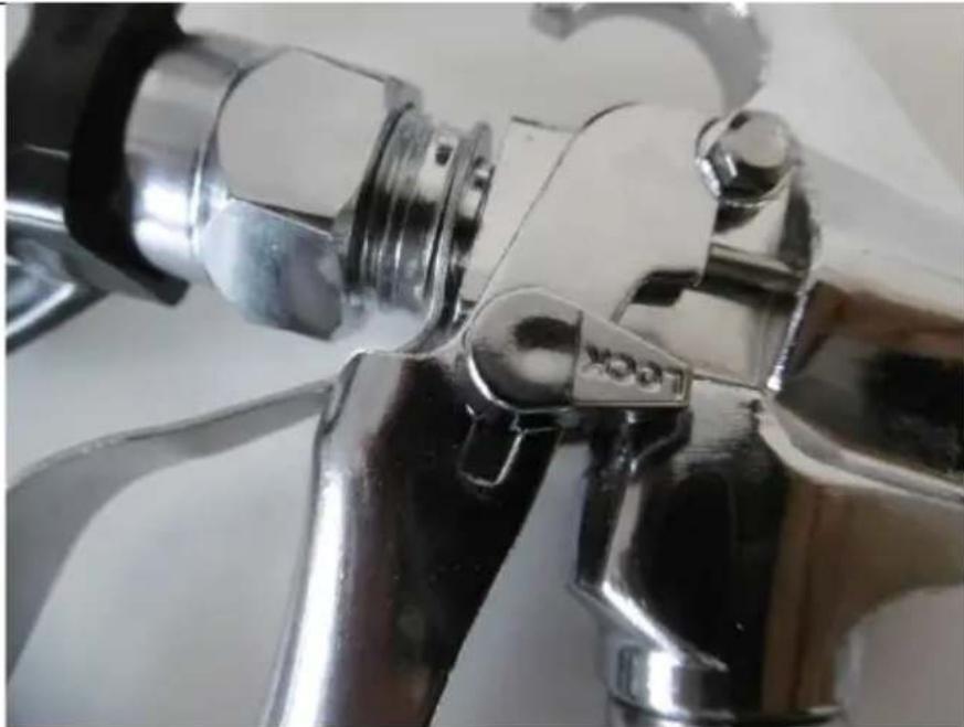
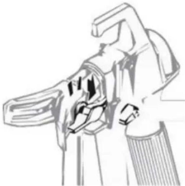
3.3.2 Locking the trigger of the spray gun
In order to block the trigger of the gun one should set the "LOCK" switch located on it perpendicularly to the gun handle. In order to unblock the trigger more or less parallel with the gun grip.
natural_image
Close-up of a metallic pipe fitting with a hexagonal bolt and handle (no visible text or symbols)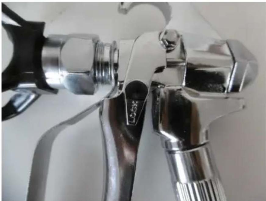
natural_image
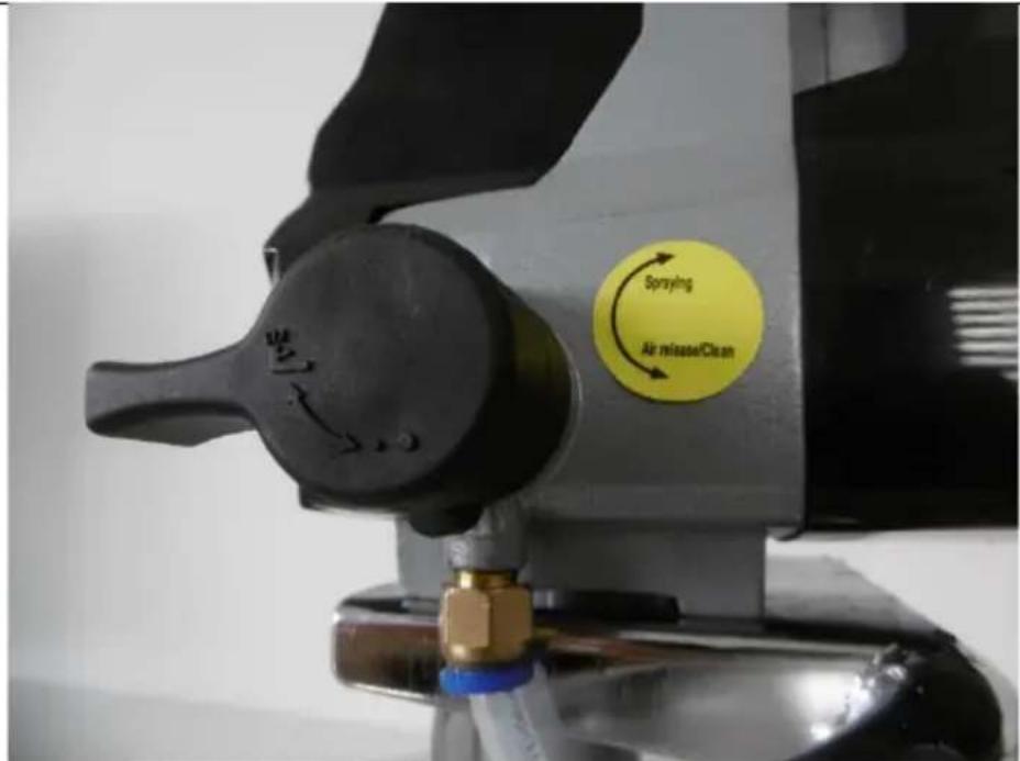
Close-up of a metallic spray gun handle with black and white adjustment knobs (no text or symbols visible)3.3.3 Getting rid of excess pressure
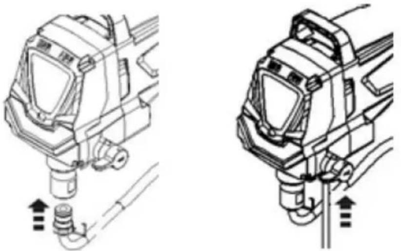
Before each time the unit is turned off, get rid of excess pressure accumulated in the air hose. To do this, you need to:
a) Remove the spray nozzle from the gun.
b) Lock the trigger in the spray gun and turn the unit off - set the ON/OFF switch to the "O" position.
c) Set the valve switch to the "Spraying" position (see the picture below).
d) Unlock the trigger of the gun and point it at the waste bucket, etc., then squeeze the trigger.
IMPORTANT: in the case of cleaning from oil-based paints, the gun should be grounded while releasing pressure - for this purpose, its metal part (e.g. the corner of the handle) should touch the metal container for paint residue that stands on the ground.
e) Keep the trigger pressed until the residual air, water or solvent escapes from the gun.
3.3.4 Spraying material
a) Making sure the ON/OFF switch is in the off ("O") position and the gun trigger is locked, install the spray nozzle in the gun tip.
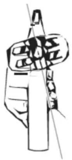
IMPORTANT: when tightening the spray nozzle in the tip before final spray setting the tip should be slightly skewed so that after tightening they are flush - see example picture below for horizontal setting:
natural_image
Line drawing of a hand holding a cylindrical object with a pointed tip (no text or symbols)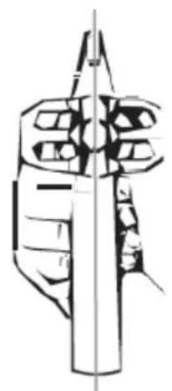
natural_image
Technical line drawing of a mechanical component or tool assembly (no text or symbols)b) Make sure the spray hose is free of debris, carbon deposits, etc.
c) Turn on the unit by setting the ON/OFF switch to the "I" position and wait until the unit generates maximum pressure (gauge reading reaches maximum for this product).
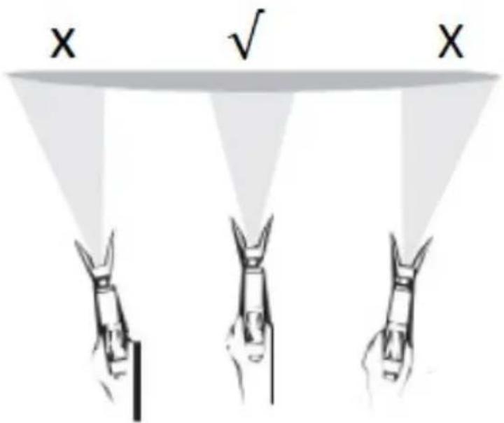
d) Once the compressor motor shuts off, i.e. maximum pressure is reached, painting can begin, however perform a small test spray first is recommended - the spray should be evenly distributed along its entire length - see the picture below:


3.3.5 Painting Tips
The key to a good result is an even layer of material over the entire painted surface.
a) The gun should be held parallel to the surface - work with your whole hand/arm, not just bend your wrist.
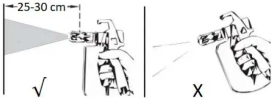
b) The gun tip should always be perpendicular to the surface being sprayed at a distance of about 25-30 cm, otherwise the paint distribution will be uneven at both ends of the spray.
c) Start spraying along the surface with and only after you have started the hand stroke do you press the trigger; likewise, when finishing, first release the trigger and continue the hand stroke for a while. Each sprayed section should overlap ca. 30 % with the previous one. Maintain an even distance from the surface to be painted as described in steps a) and b) above - see picture below:
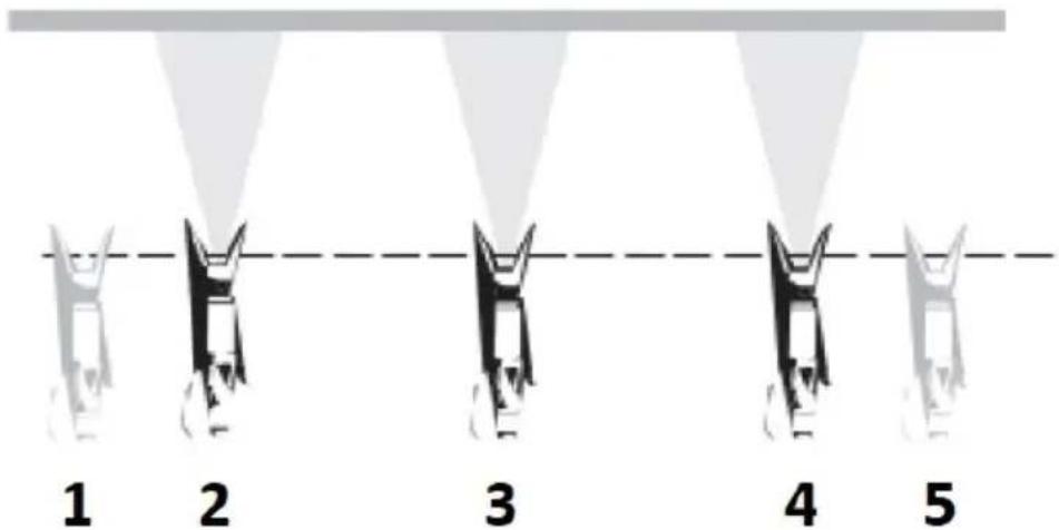
• 1 - starting the hand stroke
• 2 - pressing the trigger
• 3 - steady movement with trigger depressed
• 4 - release the trigger
- 5 - end of stroke
d) If you stop spraying material for more than an hour but less than 16 hours, lock the gun trigger, set the valve switch to the "Air release/Clean" position, turn the unit off and unplug it from the power outlet. Then slowly pour 12 cup of water on top of the paint container to prevent it from drying out, while wrapping the gun with a damp cloth and placing it in a plastic bag sealing it tightly. Place everything in a darkened area. This is called short-term storage of the unit ready for operation.
To start the unit after this time, remove the gun from the plastic bag. Mix the paint with water. Set the valve switch to "Air release/Clean" position and connect the unit to the power supply and set the ON/OFF switch to ON position. Move the valve switch to the "Spraying" position and spray on some test piece - if everything is ok, you can continue working.
3.4. Cleaning and maintenance
a) Pull the mains plug and let the unit cool down completely before cleaning, adjusting or replacing accessories and when the unit is not in use.
- Wait until the rotating parts stop.
b) Clean and maintain the unit after each use.
c) After each cleaning, all the parts should be dried well before the unit is used again.
d) Store the unit in a dry and cool place protected from moisture and direct sunlight.
e) Do not spray the unit with a stream of water or immerse it in water.
f) Make sure that no water enters through the ventilation openings in the casing.
g) Clean the ventilation openings with a brush and compressed air.
h) Latex paints should be cleaned in warm soapy water and petroleum-based paints in mineral spirits - never the other way around!
i) Before each use, inspect the equipment for operability and any damage.
j) Use a soft cloth for cleaning.
k) Do not use sharp and/or metal objects (e.g. a wire brush or metal spatula) for cleaning, as these may damage the surface of the material from which the unit is made.
I) Do not clean the unit with fuel!
3.4.1 Cleaning the blocked spray gun
If during work the spray pattern becomes uneven or material stops coming out of the gun, release the trigger and lock it in the closed position. Then turn the spray nozzle by 180° so that its "dart" points in the direction of the gun (in the cleaning position) - see the picture below.
natural_image
Line drawing of a mechanical device with internal components (no text or symbols)NOTE: under pressure the nozzle may not be able to be turned easily, so turn the valve switch to the "Air release/Cleaning" position and squeeze the trigger, this will release the pressure from the nozzle and allow it to be turned more easily.
IMPORTANT: do not use a needle or any sharp object to clean the nozzle, because it can be damaged!
Next, turn the valve knob to the "Spraying" position and spray in the direction of some test piece, allowing the pressurized air to blow away the deposits. If this happens, a steady stream of material should immediately come out of the nozzle. Then lock the trigger, rotate the spray nozzle with the arrow toward the surface to be sprayed, and once the trigger is unlocked, you can continue working. However, if this method does not improve, clean the spray gun filter (see next section).
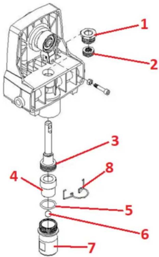
3.4.2 Cleaning the spray gun filter
CAUTION: The spray gun filter should be cleaned after each use, but more frequent cleaning may be needed if thicker paints/paints are used.
First, remove excess pressure according to the method described above in the text. Unscrew the tip at the bottom of the handle from the gun taking care not to lose the spring. Next remove the trigger guard by pulling it from the gun in the direction of the spray tip. Remove the filter from the gun housing and wash it thoroughly (use an appropriate agent depending on the type of paint sprayed). Inspect the filter strainer for holes and - if there are any, replace it. Attach the cleaned filter with its tapered tip back to the gun, making sure that everything is tightly fitted, as only this will ensure its efficient operation.
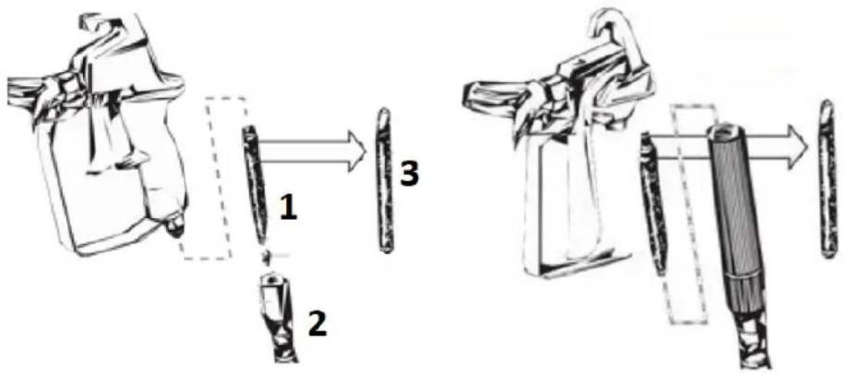
1 - filter
2 - spring
3 - tapered tip = top of the filter
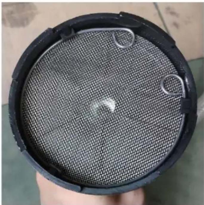
3.4.3 Cleaning the suction filter
The condition of the filter at the end of the suction hose should be checked each time the spray can is changed. To remove it, unscrew it from the suction hose and rinse it in a solution of warm soapy water or spirit - depending on the spray material used (see details in the previous section).
natural_image
Top-down view of a black mesh filter or filter component with visible internal structure and two metal clips (no text or symbols)3.4.4 Cleaning after working with petroleum-based materials
a) Lock the gun trigger and remove the spray nozzle, and immerse the suction hose with strainer in a container of suitable cleaning solution.
b) Place a waste container next to the material container, and aim the spray gun at the side of the material container and hold the trigger.
c) While pulling the trigger, turn on the machine and turn the valve switch to the "Spraying" position to dispose of the spray material back into the original container.
IMPORTANT: Throughout the next steps, keep the trigger pressed at all times.
d) While cleaning solution starts coming out of the gun tip instead of the spray material, direct the spray into the waste container remembering to ground the gun e.g. by touching it against the side of the metal container.
e) As soon as clean cleaning solution starts coming out of the gun, release the trigger.
f) Turn the valve switch to the "Air release/Cleaning" position and pull the trigger to release the pressure from the system.
3.4.5 Cleaning the suction kit
a) Lock the gun trigger and turn off the unit.
b) Disconnect the suction and return hoses from the unit and clean them in suitable solutions. While doing so, clean the spigot thread and the suction set filter (see following image).
c) After cleaning the aspiration kit, connect it back to the unit and lock it.
natural_image
Technical line drawings of two mechanical components with directional arrows indicating movement or force (no text or symbols present)d) Dip the end of the aspiration tube with the strainer into a bucket of fresh cleaning solution.
e) Set the valve switch to the "Air release/Cleaning" position, then turn on the unit and, pointing the gun tip into the waste tank, press the trigger, allowing the pump to run for 2-3 minutes to flush it well.
f) Turn off the unit - ON/OFF switch in position "O".
IMPORTANT: in case of previous oil based paint spraying it will be still necessary to rinse the pump and the gun with water solution before further storage.
3.4.6 Cleaning the spray gun
a) Ensure that the unit is switched off (ON/OFF switch in position "O") and the valve in position "Air release/Cleaning".
b) Detach the spray gun from the air hose using a wrench.
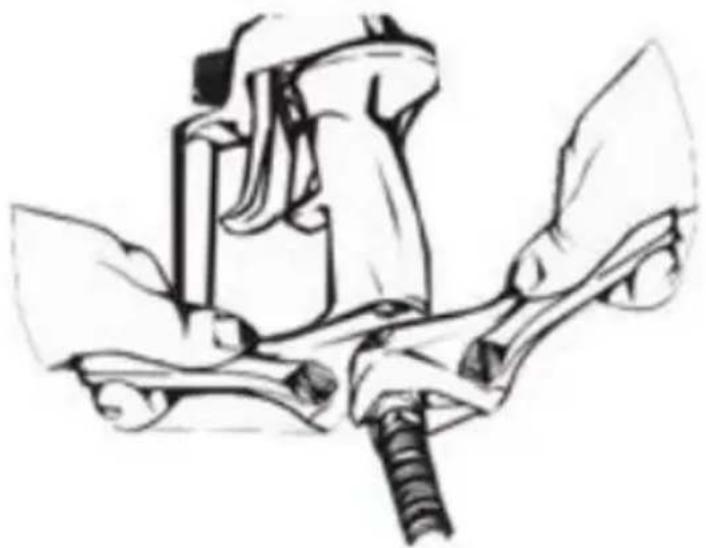
natural_image
Line drawing of a mechanical device with a tool and base, no text or symbols presentb) Clean the spray gun filter - see more in subsection 3.4.2.
c) Remove the spray tip nozzles from the tip and clean them, also remembering to remove the washer (1) and "saddle" (2) located at the back of the spray tip. Clean with a soft bristle brush and the proper solution.
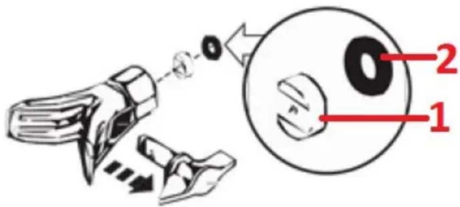
d) Reinstall the filter in the spray gun handle and the spray nozzle with hardware in the spray tip.
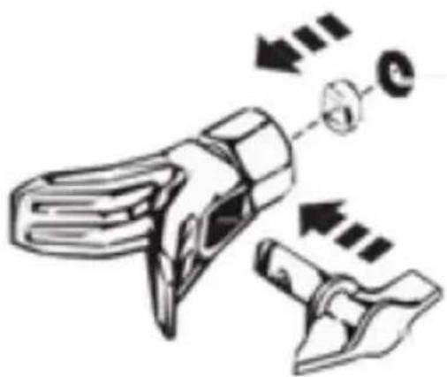
natural_image
Diagram of a mechanical device with arrows indicating motion or force direction (no text or symbols)e) Twist the spray gun and hose together.
3.4.7 Long-term storage
IMPORTANT: the unit can only be stored long-term if it has been thoroughly cleaned on the inside - see previous cleaning steps.
a) Fill a cup or other container with approx. 60 ml of "TSL" interior separation oil (supplied) and place it under the suction valve to soak it in.
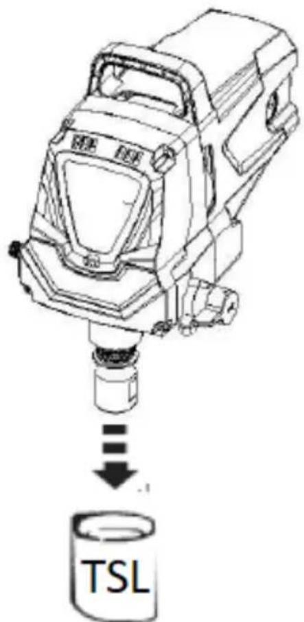
b) Place the cloth on the nozzle of the outlet valve and set the valve switch to the "Spraying" position.
c) Turn the machine on with the ON/OFF switch and if all the "TSL" oil is sucked out of the container, turn it off immediately. Wipe the unit clean of the ejected oil.
natural_image
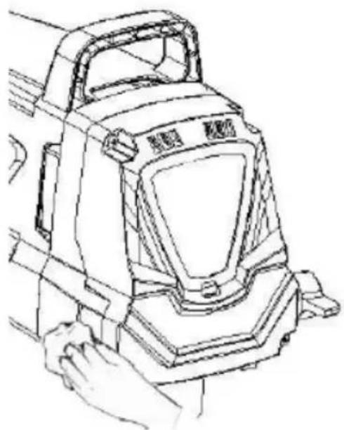
Line drawing of a mechanical device with hands operating it (no text or symbols)3.4.8 Cleaning the suction valve
Cleaning the suction valve may be necessary if the unit is having trouble cleaning itself and getting rid of debris. To do this, you need to:
a) Remove the suction hose from the valve.
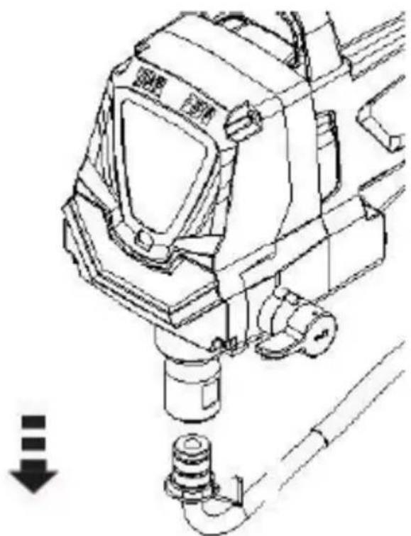
natural_image
Technical line drawing of a mechanical assembly with no visible text or symbolsb) Unscrew the suction valve housing from the unit and assess its condition. Clean it of residues in a suitable solution.
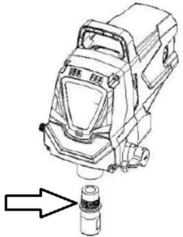
natural_image
Technical line drawing of a mechanical device with an arrow pointing to a cylindrical component (no text or symbols present)c) Lubricate its O-ring and reassemble it in the unit by tightening it with a torque of 31-36 Nm.
d) Reinstall the suction hose with the strainer at the end.
3.4.9 Replacing the suction apparatus seals
IMPORTANT: before servicing the seals, first relieve any accumulated pressure in the unit and hose - see more details in the "Working with the unit" section. Then disconnect the unit from the power source.
a) Disconnect the suction hose.
b) Unscrew the front housing - 4 T20 torx screws.
c) Remove the yoke bolt and washer securing the locking pin that connects the yoke to the piston.
d) Rotate the pump shaft so that the piston is in the top dead center position - this can be done by pushing the yoke. This is necessary to remove the necessary parts.
e) Unscrew and remove the valve assembly.
f) Remove the piston assembly by pushing it down around the yoke.
g) Unscrew and remove the top nut using an adjustable wrench.
h) Remove the worn sealers using a flathead screwdriver or drift. Remove the upper seal from the top and the lower seal from the bottom by pressing on its sides and pulling it out. When doing so, be careful not to scratch the surface the sealers are sitting on.
i) Clean the surfaces for the new sealers.
- Top Nut
- Top seal
- Piston Seal Kit
- Retaining flange
- Sealing ring
- Steel balls
- Valve body
- Locking ring
j) Lubricate the new upper seal with the supplied "TSL" oil and manually place it with the seal down into the upper housing bore.
k) Apply a small amount of threadlock lubricant to the threads of the upper nut. Place the top nut on top of the housing and tighten it. This will push the top seal into position.
I) Place the unit upside down. Lubricate the lower seal and its set like the upper seal and place it at the bottom of the housing. Set the piston with the seal - press down until it settles.
m) Put a new ring seal on the intake valve set and lubricate it with "TSL" oil, then screw it in from the bottom (inlet) of the housing. This should set the seal in the correct position.
n) Align the piston to the yoke taking care not to damage the piston.
o) Lubricate the piston and the area around the yoke with grease to extend their life. Apply grease to the holes in the yoke where the plunger is inserted.
p) Install the locking pin to connect the yoke to the piston - it may be necessary to move the piston up or down to do this.
q) Screw in the yoke screw and washer to secure the locking pin.
r) Set the unit back on its feet and add a few drops of "TSL" oil between the top nut and the piston.
s) Replace the front casing and tighten it with the 4 screws.
t) Replace the inlet valve and attach the suction hose kit.
DISPOSAL OF USED UNITS.
At the end of its useful life, this product should not be disposed of with normal household waste but should be taken to a collection point for the recycling of electrical and electronic equipment. This is indicated by the symbol on the product, operating instructions or packaging. The materials used in this unit are recyclable according to their marking. You will be making an important contribution to protecting our environment by reusing, recycling or otherwise disposing of used units.
Your local administration will provide you with information about the appropriate disposal point for used units.
TROUBLESHOOTING
| Problem | Possible cause | Action |
| A. The unit does not start. | a) The unit is not connected to the power supply.b) The ON/OFF switch is in the "O" (off) position.c) No power at the outlet.d) Power cord or extension cord damaged.e) Fuse blown in the machine.f) Problem with the unit's motor. | a) Connect the unit to the power supply.b) Set the ON/OFF switch to the on ("I") position.c) Check power at outlet and/or building wiring, etc.d) Replace/repair the power cord or the extension cord.e) Contact the manufacturer's service department.f) Contact the manufacturer's service department. |
| B. The machine starts but does not draw paint when the valve switch is in the "Air release/Cleaning" position. | a) The strainer at the end of the suction hose has not been thoroughly immersed in the ink container or the ink in the container has run out.b) Clogged aspiration tube or strainer at the beginning of the aspiration tube.c) Attachment of the suction hose to the suction valve is loose.d) Blocked aspiration valve.e) Blocked outlet valve.f) Suction valve defective.g) Valve switch blocked. | a) Fill the container with paint or immerse it in paint material.b) Clean the aspiration unit.c) Correct the fastening of the aspiration hose.d) Clean the aspiration valve.e) Dismantle the aspiration valve and insert e.g. a pen through the aspiration valve to unblock the outlet valve.f) Replace the aspiration valve.g) Contact the manufacturer's service department. |
| C. The unit sucks paint, but the pressure drops when the trigger is pressed. | a) Spray worn nozzle.b) Screen filter of the suction unit is blocked.c) Clogged filter in the spray gun.d) Paint too thick or lumpy.e) Suction valve assembly is damaged or worn.f) Suction hose is loose. | a) Replace the spray nozzle.b) Clean the strainer strainer.c) Clean and, if necessary, replace the gun filter.d) Dilute or strain the paint.e) Replace the suction valve.f) Correct the attachment of the suction hose. |
| D. Valve switch is in "Spraying" position but paint returns through the return hose. | Changeover valve dirty or worn. | Contact the manufacturer's service department. |
| E. Spray gun is leaking. | Components inside the spray gun are worn or contaminated. | Contact the manufacturer's service department. |
| F. The spray nozzle is leaking. | a) Incorrectly installed nozzle.b) Washer worn. | a) Check and correct the nozzle attachment.b) Replace washer. |
| G. The spray gun is not spraying paint. | a) Spray nozzle blocked.b) Spray nozzle position is not set for spraying. | a) Clean nozzles or gun filter.b) Set the spray nozzle properly for spraying. |
| H. The spray pattern is uneven over the entire surface. | a) Air pressure too low.b) The spray gun or suction apparatus screen filter is clogged.c) The suction hose is loose at the suction valve.d) Spray worn nozzle.e) Paint too thick.f) Pressure drops. | a) Wait for the unit to build up pressure or contact the manufacturer's service department.b) Clean the filters.c) Correct the fastening of the aspiration hose.d) Replace the spray nozzle.e) Thin the paint.f) See problem under "C" and its cause and solution. |
Assembly drawing:
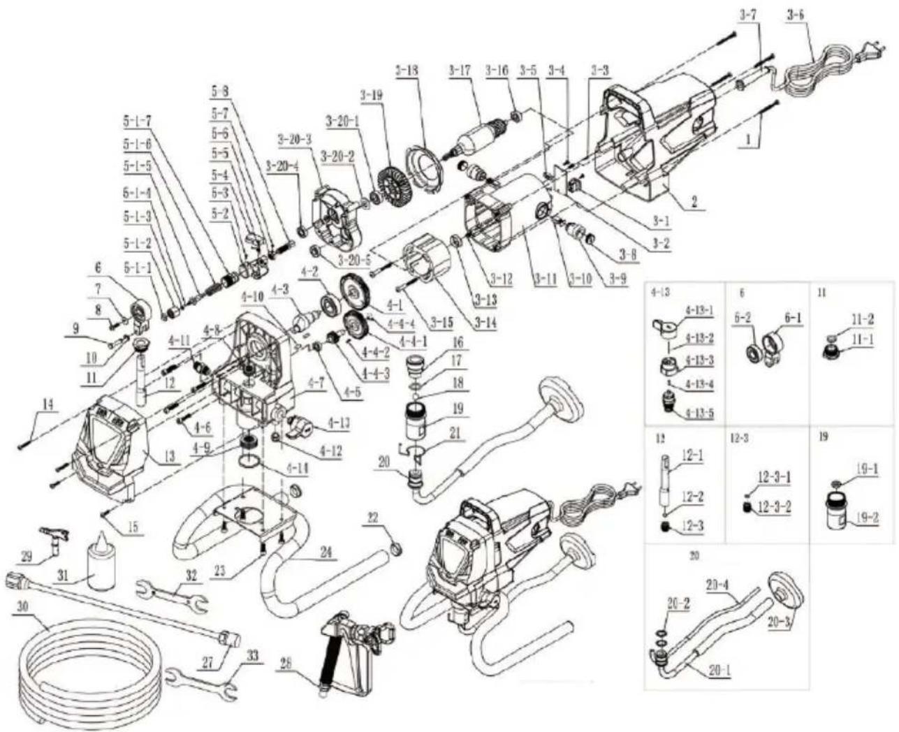
| Number | Description of the | Quantity |
| 1 | Screw | 4 |
| 2 | Motor housing | 1 |
| 3 | Motor set | 1 set |
| 3-1 | Switch | 1 |
| 3-2 | Printed circuit board | 1 |
| 3-3 | Screw | 2 |
| 3-4 | Screw | 2 |
| 3-5 | Cable clamping | 1 |
| 3-6 | Cable | 1 |
| 3-7 | Cable cover | 1 |
| 3-8 | Carbon brush cover | 2 |
| 3-9 | Carbon brush holder | 2 |
| 3-10 | Carbon Brush | 2 |
| 3-11 | Internal motor housing | 1 |
| 3-12 | screw | 4 |
| 3-13 | Bearing cover | 1 |
| 3-14 | Stand | 1 |
| 3-15 | Screw | 2 |
| 3-16 | Bearing 608-Z | 1 |
| 3-17 | Rotor | 1 |
| 3-18 | Fan cover | 1 |
| 3-19 | Fan | 1 |
| 3-20 | Middle cover assembly | 1 set |
| 3-20-1 | Bearing 6000RS | 1 |
| 3-20-2 | Woolen mat | 1 |
| 3-20-3 | Middle cover | 1 |
| 3-20-4 | Bearing 699-Z | 1 |
| 3-20-5 | Bearing 608-Z | 1 |
| 3-21 | Ring pull rod | 2 |
| 4 | Gear set | 1 set |
| 4-1 | Large gear | 1 |
| 4-2 | Bearing 6004RS | 1 |
| 4-3 | Eccentric shaft | 1 |
| 4-4 | Small gear set | 1 set |
| 4-4-1 | Small gear | 1 |
| 4-4-2 | Woodruff key | 1 |
| 4-4-3 | Small gear shaft | 1 |
| 4-4-4 | Seger Ring | 1 |
| 4-5 | Bearing 698-Z | 1 |
| 4-6 | Screw | 4 |
| 4-7 | Gear box | 1 |
| 4-8 | Upper sealing ring | 1 |
| 4-9 | Lower the sealing ring | 1 |
| 4-10 | Holder pin | 2 |
| 4-11 | Outlet spigot | 1 |
| 4-12 | Return hose coupling | 1 |
| 4-13 | Non-return valve assembly | 1 set |
| 4-13-1 | Knob | 1 |
| 4-13-2 | Holder pin | 1 |
| 4-13-5 | Pressure valve assembly | 1 set |
| 4-14 | O-ring | 1 |
| 5 | Pressure regulating valve | 1 set |
| 5-1 | Pressure valve kit | 1 set |
| 5-1-1 | Pressure valve housing sealing ring | 1 |
| 5-1-2 | Pressure valve housing | 1 |
| 5-1-3 | Pressure valve stem sealing ring | 1 |
| 5-1-4 | Pressure control valve gasket | 1 |
| 5-1-5 | Pressure control valve stem | 1 |
| 5-1-6 | Pressure regulating spring | 1 |
| 5-1-7 | Pressure regulating knob | 1 |
| 5-2 | Pressure valve cover | 1 |
| 5-3 | Screw | 1 |
| 5-4 | Microswitch | 1 |
| 5-5 | Spring | 1 |
| 5-6 | Screw | 1 |
| 5-7 | Knob nut | 1 |
| 5-8 | Speed controller | 1 |
| 6 | Crankset set | 1 set |
| 6-1 | Crankset | 1 |
| 6-2 | Bearing 6201RS | 1 |
| 7 | Gasket | 1 |
| 8 | Screw | 1 |
| 9 | Cap | 1 |
| 10 | Split pad | 1 |
| 11 | Compression nut assembly | 1 set |
| 11-1 | Compression nut | 1 |
| 11-2 | Piston guide bushing | 1 |
| 12 | Piston set | 1 set |
| 12-1 | Piston | 1 |
| 12-2 | Steel ball piston | 1 |
| 12-3 | Lock screw set | 1 set |
| 12-3-1 | Piston seat | 1 |
| 12-3-2 | Locking screw | 1 |
| 13 | Front housing | 1 |
| 14 | Screw | 2 |
| 15 | Screw | 2 |
| 16 | Locking sleeve for lower intake valve | 1 |
| 17 | Sealing ring for bottom suction tap | 1 |
| 18 | Steel ball for bottom suction valve | 1 |
| 19 | Bottom suction valve kit | 1 set |
| 19-1 | Lower intake valve seat | 1 |
| 19-2 | Lower intake valve housing | 1 |
| 20 | Suction hose set | 1 set |
| 20-1 | Suction hose | 1 |
| 20-2 | O-ring | 2 |
| 20-3 | Suction strainer | 1 |
| 20-4 | Return hose | 1 |
| 21 | Fixing ring for bottom suction | 1 |
| 22 | Foot pivot | 2 |
| 23 | Screw | 4 |
| 24 | Leg | 1 set |
| 27 | Extension tube | 1 |
| 28 | Spray gun | 1 |
| 29 | Spray nozzle | 1 |
| 30 | Air hose (reinforced) | 1 |
| 31 | TSL oil | 1 |
| 32 | Wrench | 1 |
| 33 | Wrench | 1 |
Dane techniczne
natural_image
Close-up of a pressure gauge with metal fittings and tubing (no visible text or symbols)natural_image
Close-up of metallic mechanical connectors with a red cap, no visible text or symbols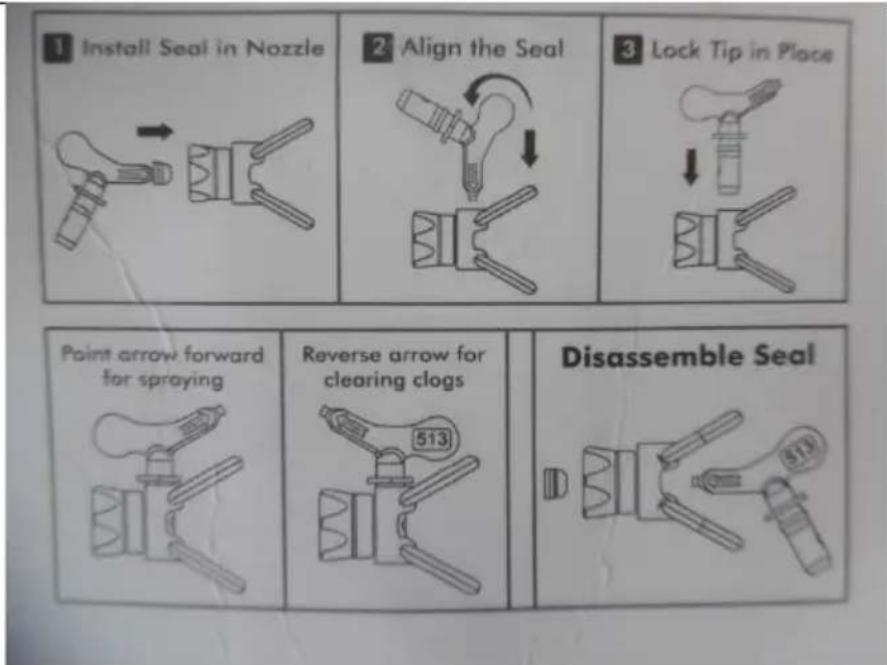
natural_image
Close-up of a metallic pump assembly with tubing and a blue valve, no visible text or symbolsnatural_image
Line drawing of a paintbrush and paint can with a tool, no text or symbols presentnatural_image
Close-up of a metallic pipe fitting with hexagonal connectors and a black cap (no visible text or symbols)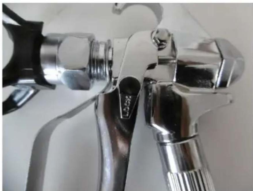
natural_image
Close-up of a metallic showerhead with black handle and threaded shaft (no visible text or symbols)natural_image
Line drawing of a hand holding a cylindrical object with a handle, no text or symbols present
natural_image
Technical line drawing of a mechanical component or tool assembly (no text or symbols)natural_image
Line drawing of a mechanical device with internal components (no text or symbols)natural_image
Top-down view of a black circular filter or mesh structure with metal clips, viewed from above (no text or symbols visible)natural_image
Technical line drawing of a mechanical device with two views (top and side), showing internal components and directional arrows (no text or symbols)natural_image
Line drawing of a mechanical device with a tool and base, no text or symbols presentnatural_image
Diagram of a mechanical device with arrows indicating motion or assembly (no text or symbols)natural_image
Line drawing of a mechanical device with hands operating it (no text or symbols)natural_image
Technical line drawing of a mechanical assembly with no visible text or symbolsnatural_image
Technical line drawing of a mechanical device with an arrow pointing to a cylindrical component (no text or symbols present)natural_image
Close-up of a pressure gauge with metal fittings and tubing, no visible text or symbolsnatural_image
Close-up of metallic mechanical connectors with a red circular end, no visible text or symbols
natural_image
Close-up of a laboratory setup with a metallic pump, tubing, and a transparent tubing with blue connectors (no visible text or symbols)natural_image
Line drawing of a paintbrush and paint can with a tool, no text or symbols presentnatural_image
Close-up of a metallic pipe fitting with a hexagonal bolt and handle (no visible text or symbols)
natural_image
Close-up of a metallic spray gun handle with black and white adjustment knobs (no text or symbols visible)3.3.3 Odtlakování
natural_image
Line drawing of a hand holding a cylindrical object with a pointed tip (no text or symbols)
natural_image
Technical line drawing of a mechanical component or tool assembly (no text or symbols)natural_image
Line drawing of a mechanical device with internal components (no text or symbols)1 - filtr
2 – pružina
natural_image
Top-down view of a black circular filter or mesh structure with visible internal structure and two metal clips (no text or symbols)natural_image
Technical line drawings of mechanical components, showing two views with arrows indicating motion or assembly (no text or symbols present)natural_image
Illustration of a mechanical device with a tool and base, no visible text or symbolsnatural_image
Diagram of a mechanical device with directional arrows indicating motion or force (no text or symbols)natural_image
Line drawing of a handheld device with a handle and control panel (no text or symbols)natural_image
Technical line drawing of a mechanical device with no visible text or symbolsnatural_image
Technical line drawing of a surveying instrument with an arrow pointing to it (no text or symbols present)natural_image
Close-up of a pressure gauge with metal fittings and a threaded connector (no visible text or symbols)natural_image
Close-up of a metallic pipe fitting with a red cap and coiled spring, against a plain background (no text or symbols visible)natural_image
Close-up of a laboratory setup with a metallic pump, tubing, and a transparent tubing with blue connectors (no visible text or symbols)natural_image
Line drawing of a paintbrush and paint can with a tool, no text or symbols presentnatural_image
Close-up of a metallic pipe fitting with connectors and fittings (no visible text or symbols)
natural_image
Close-up of a metallic spray gun handle with black and silver components (no visible text or symbols)natural_image
Line drawing of a hand holding a cylindrical object with a pointed tip (no text or symbols)
natural_image
Technical line drawing of a mechanical component or tool assembly (no text or symbols)natural_image
Line drawing of a mechanical device with internal components (no text or symbols)1 - filtre
2 - ressort
natural_image
Top-down view of a black circular filter or mesh structure with metal clips, held by a hand (no text or symbols visible)natural_image
Technical line drawings of two mechanical components with directional arrows indicating movement or assembly (no text or symbols present)natural_image
Line drawing of a mechanical device with a tool and base, no text or symbols presentnatural_image
Diagram of a mechanical component with arrows indicating motion or force direction (no text or symbols)natural_image
Line drawing of a hand operating a mounted device with no visible text or symbolsnatural_image
Technical line drawing of a mechanical device with no visible text or symbolsnatural_image
Technical line drawing of a mechanical device with a cylindrical component inserted, showing no text or symbols.natural_image
Close-up of a pressure gauge with metal fittings and tubing, no visible text or symbolsnatural_image
Close-up of metallic mechanical connectors with a red cap, no visible text or symbolsnatural_image
Close-up of a metallic pump assembly with tubing and tubing, no visible text or symbolsnatural_image
Line drawing of a paintbrush and paint can with a tool, no text or symbols presentnatural_image
Close-up of a metallic pipe fitting with brass fittings and metal fittings (no visible text or symbols)
natural_image
Close-up of a metallic showerhead with black handle and blue fittings (no visible text or symbols)natural_image
Line drawing of a hand holding a cylindrical object with a handle, no text or symbols present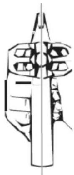
natural_image
Technical line drawing of a mechanical component or tool assembly (no text or symbols)natural_image
Line drawing of a mechanical device with internal components (no text or symbols)natural_image
Top-down view of a black circular filter or mesh structure with metal clips, held by a hand (no text or symbols visible)natural_image
Technical line drawings of two mechanical components with directional arrows indicating movement or assembly (no text or symbols present)natural_image
Line drawing of a mechanical device with a tool and base, no text or symbols presentnatural_image
Diagram of a mechanical component with arrows indicating motion or force direction (no text or symbols)e) Avvitare la pistola al tubo flessibile.
natural_image
Line drawing of a hand operating a mounted device with no visible text or symbolsnatural_image
Technical line drawing of a mechanical device with no visible text or symbolsnatural_image
Technical line drawing of a mechanical device with a cylindrical component inserted, showing no text or symbols.natural_image
Close-up of a pressure gauge with metal fittings and tubing, no visible text or symbolsnatural_image
Close-up of a mechanical component with metallic fittings and a red button, no visible text or symbolsnatural_image
Close-up of a medical procedure in progress, showing tubing, tubing fittings, and a metallic pump (no visible text or symbols)natural_image
Line drawing of a paintbrush and paint can with a tool, no text or symbols presentnatural_image
Close-up of a metallic pipe fitting with a hexagonal bolt and handle (no visible text or symbols)
natural_image
Close-up of a metallic showerhead with black handle and threaded shaft (no text or symbols visible)natural_image
Line drawing of a hand holding a cylindrical object with a pointed tip (no text or symbols)
natural_image
Technical line drawing of a mechanical component or tool assembly (no text or symbols)natural_image
Line drawing of a mechanical device with internal components (no text or symbols)1 - filtro
2 - muelle
3 - Extremo estrecho = parte superior del filtro
natural_image
Top-down view of a black mesh filter or filter component with visible internal structure and two metallic clips (no text or symbols)natural_image
Technical line drawings of two mechanical components with directional arrows indicating movement or force (no text or symbols present)natural_image
Line drawing of a mechanical assembly with a tool and base (no text or symbols)natural_image
Diagram of a mechanical device with directional arrows indicating motion or force (no text or symbols)e) Conecte la pistola a la manguera.
natural_image
Line drawing of a hand operating a portable air conditioner unit (no text or symbols)natural_image
Technical line drawing of a mechanical device with no visible text or symbolsnatural_image
Technical line drawing of a mechanical device with a cylindrical component inserted, showing no text or symbols.natural_image
Close-up of a metallic pressure gauge with threaded connectors and fittings (no visible text or symbols)natural_image
Close-up of metallic mechanical connectors with a red circular end, attached to a black plastic component (no text or symbols visible)natural_image
Hand holding a black mechanical device next to an orange printed package with a purple tool and label (no readable text on device or background)
natural_image
Close-up of a metallic pump assembly with tubing and a blue valve, no visible text or symbolsnatural_image
Line drawing of a paintbrush and paint can with a tool, no text or symbols presentnatural_image
Close-up of a metallic pipe fitting with a hexagonal bolt and handle (no text or symbols visible)
natural_image
Close-up of a metallic spray gun handle with black and white adjustment knobs (no text or symbols visible)natural_image
Line drawing of a hand holding a cylindrical object with a pointed tip (no text or symbols)
natural_image
Technical line drawing of a mechanical component or tool assembly (no text or symbols)
3.3.5 Festési tippek
natural_image
Line drawing of a mechanical device with internal components (no text or symbols)1 - szűrő
2 - rugó
natural_image
Top-down view of a black circular filter or mesh structure with visible internal structure and two metal clips (no text or symbols)natural_image
Technical line drawings of mechanical components, showing two views with arrows indicating motion or assembly (no text or symbols present)natural_image
Illustration of a mechanical device with a tool and base, no visible text or symbolsnatural_image
Diagram of a mechanical device with arrows indicating motion or force direction (no text or symbols)natural_image
Line drawing of a hand operating a portable air conditioner unit (no text or symbols)natural_image
Technical line drawing of a mechanical device with no visible text or symbolsnatural_image
Technical line drawing of a mechanical device with a cylindrical component inserted, showing no text or symbols.APPARATETS PLACERING
natural_image
Close-up of a metallic pressure gauge with threaded connectors and fittings (no visible text or symbols)natural_image
Close-up of metallic mechanical connectors with a red circular end, no visible text or symbols
natural_image
Close-up of a metallic pump assembly with tubing and a blue valve, no visible text or symbolsnatural_image
Line drawing of a paintbrush and paint can with a brush, no text or symbols presentnatural_image
Close-up of a metallic pipe fitting with bolts and fittings (no visible text or symbols)
natural_image
Close-up of a metallic spray gun with black handle and blue fittings (no visible text or symbols)natural_image
Line drawing of a hand holding a cylindrical object with a grid-like structure (no text or symbols)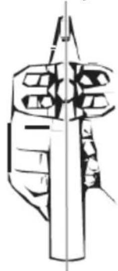
natural_image
Technical line drawing of a mechanical component or tool assembly (no text or symbols)natural_image
Line drawing of a mechanical device with internal components (no text or symbols)1 - filter
2 - fjeder
3 - Tilspidset spids = toppen af filteret
natural_image
Top-down view of a black plastic filter or mesh structure with visible internal structure and two metal clips (no text or symbols)natural_image
Technical line drawing of two mechanical components with directional arrows indicating movement or assembly (no text or symbols present)natural_image
Line drawing of a mechanical assembly with a tool and base (no text or symbols)natural_image
Diagram of a mechanical device with arrows indicating motion or assembly (no text or symbols)e) Skru pistolen med slangen.
3.4.7 Langtidsopbevaring
natural_image
Line drawing of a mechanical device with hands operating it (no text or symbols)natural_image
Technical line drawing of a mechanical assembly with no visible text or symbolsnatural_image
Technical line drawing of a mechanical device with an arrow pointing to a cylindrical component (no text or symbols present)For the disposal of the device please consider and act according to the national and local rules and regulations.
CONTACT
expondo Polska sp. z o.o. sp. k.