
RCVG-47-1 - Vacuum packaging machines Royal Catering - Free user manual and instructions
Find the device manual for free RCVG-47-1 Royal Catering in PDF.

| Product type | Professional vacuum machine |
| Model | RCVG-47-1 |
| Brand | Royal Catering |
| Usage | Domestic |
| Power supply | 230 V~ / 50 Hz |
| Power | 1000 W |
| Dimensions (L x D x H) | 460 x 310 x 340 mm |
| Weight | 24 kg |
| Adjustable vacuum time | 5 to 90 seconds |
| Adjustable sealing time | 0 to 6 seconds |
| Display | LED screen with time and pressure indicators |
| Pressure gauge | Integrated pressure indicator |
| Manual sealing function | Yes (SEAL button) |
| Automatic restart | Yes, after lid closure |
| Factory reset | Yes (SEAL+SET buttons) |
| Pump maintenance | Oil filling/draining required |
| Cleaning | Soft damp cloth, non-corrosive detergents |
| Safety | Lockable lid, automatic shut-off, contact protection |
| Operating conditions | Ambient temperature < 40°C, humidity < 85% |
| Minimum safety distance | 10 cm from walls |
Frequently Asked Questions - RCVG-47-1 Royal Catering
User questions about RCVG-47-1 Royal Catering
0 question about this device. Answer the ones you know or ask your own.
Ask a new question about this device
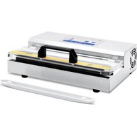
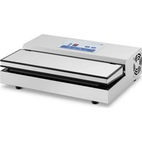
Download the instructions for your Vacuum packaging machines in PDF format for free! Find your manual RCVG-47-1 - Royal Catering and take your electronic device back in hand. On this page are published all the documents necessary for the use of your device. RCVG-47-1 by Royal Catering.
USER MANUAL RCVG-47-1 Royal Catering
natural_image
Abstract white line drawing of a mythical creature on a blue background (no text or symbols)| DE | Produktname | VAKUUMIERGERÄT |
| EN | Product name | VACUUM PACKING MACHINE |
| PL | Nazwa produktu | PAKOWARKA PRÓŻNIOWA KOMOROWA |
| CZ | Název výrobku | VAKUOVAČKA |
| FR | Nom du produit | MACHINE SOUS VIDE PROFESSIONNELLE |
| IT | Nome del prodotto | MACCHINA SOTTOVUOTO PER ALIMENTI |
| ES | Nombre del producto | ENVASADORA PARA ALIMENTOS |
| HU | Termék neve | VÁKUUMOZÓ GÉP |
| DA | Produktnavn | KAMMER-VAKUUMPAKKER |
| FI | Tuotteen nimi | VAKUUMIKONE |
| NL | Productnaam | VACUUMSEALER |
| NO | Produktnavn | VAKUUMPAKKER |
| SE | Produktnamn | VAKUUMFÖRPACKARE |
| PT | Nome do produto | MÁQUINA DE EMBALAR A VÁCUO COM CÂMARA |
| SK | Názov produktu | VÁKUOVAČKA |
| DE | Modell | RCVG-47-1 |
| EN | Product model | |
| PL | Model produktu | |
| CZ | Model výrobku | |
| FR | Modèle | |
| IT | Modello | |
| ES | Modelo | |
| HU | Modell | |
| DA | Model | |
| FI | Tuotteen malli | |
| NL | Productmodel | |
| NO | Produktmodell | |
| SE | Produktmodell | |
| PT | Modelo do produto | |
| SK | Model | |
| DE | Hersteller | expondo Polska sp. z o.o. sp. k. |
| EN | Manufacturer | |
| PL | Producent | |
| CZ | Výrobce | |
| FR | Fabricant | |
| IT | Produttore | |
| ES | Fabricante | |
| HU | Termelő | |
| DA | Producent | |
| FI | Valmistaja | |
| NL | Producent | |
| NO | Produsent | |
| SE | Tillverkare | |
| PT | Fabricante | |
| SK | Výrobca | |
| DE | Anschrift des Herstellers | ul. Nowy Kisielin – Innowacyjna 7, 66-002 Zielona Góra | Poland, EU |
| EN | Manufacturer Address | |
| PL | Adres producenta | |
| CZ | Adresa výrobce | |
| FR | Adresse du fabricant | |
| IT | Indirizzo del produttore | |
| ES | Dirección del fabricante | |
| HU | A gyártó címe | |
| DA | Producentens adresse | |
| FI | Valmistajan osoite | |
| NL | Adres producent | |
| NO | Produsentens adresse | |
| SE | Tillverkarens adress | |
| PT | Endereço do fabricante | |
| SK | Adresa výrobcu |

natural_image
Interior view of a stainless steel water heater with a hand pouring liquid into a blue tank (no visible text or symbols)natural_image
Metallic electronic component with two circular holes and a pointer indicating a specific point (no text or symbols visible)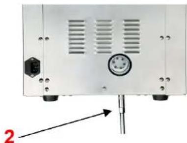
natural_image
Front view of a white electronic device with ventilation slots and a pressure gauge, mounted on a stand (no visible text or symbols)1 - Schraubkappe; 2 - Schraubenschlüssel
This User Manual has been translated for your convenience using machine translation. Reasonable efforts have been made to provide an accurate translation; however, no automated translation is perfect nor is it intended to replace human translators. The official User Manual is the English version. Any discrepancies or differences created in the translation are not binding and have no legal effect for compliance or enforcement purposes. If any questions arise related to the accuracy of the information contained in the User Manual, please refer to the English version of those contents which is the official version.
Technical data
| Parameter description Parameter value | |
| Product name | Vacuum Packing Machine |
| Model | RCVG-47-1 |
| Rated voltage [V~] / frequency [Hz] | 230/50 |
| Rated power [W] | 1000 |
| Dimensions [width x depth x height; mm] | 460x310x340 |
| Weight [kg] | 24 |
1. General description
The user manual is designed to assist in the safe and trouble-free use of the device. The product is designed and manufactured in accordance with strict technical guidelines, using state-of-the-art technologies and components. Additionally, it is produced in compliance with the most stringent quality standards.
DO NOT USE THE DEVICE UNLESS YOU HAVE THOROUGHLY READ AND UNDERSTOOD THIS USER MANUAL.
To increase the product life of the device and to ensure trouble-free operation, use it in accordance with this user manual and regularly perform maintenance tasks. The technical data and specifications in this user manual are up to date. The manufacturer reserves the right to make changes associated with quality improvement. The device is designed to reduce noise emission risks to a minimum, taking into account technological progress and noise reduction opportunities.
Legend

The product satisfies the relevant safety standards.
Read instructions before use.
The product must be recycled.
WARNING! or CAUTION! or REMEMBER! Applicable to the given situation. (general warning sign)
ATTENTION! Electric shock warning!
ATTENTION! Hand crush hazard!
ATTENTION! Hot surface, risk of burns!
Only use indoors.

PLEASE NOTE! Drawings in this manual are for illustration purposes only and in some details may differ from the actual product.
2. Usage safety

ATTENTION! Read all safety warnings and all instructions. Failure to follow the warnings and instructions may result in electric shock, fire and/or serious injury or even death.
The terms "device" or "product" are used in the warnings and instructions to refer to:
Vacuum packing machine
2.1. Electrical safety
a) The plug of this unit must fit into the outlet. Do not modify the plug in any way. Original plugs and matching outlets reduce the risk of electric shock.
b) Do not touch the unit with wet or damp hands.
c) Do not use the cord in an unintended manner. Never use it to carry the unit or to pull the plug out of the socket. Keep the cord away from heat sources, oil, sharp edges or moving parts. Damaged or tangled cords increase the risk of electric shock.
d) If you cannot avoid using the unit in a wet environment, use a residual current unit (RCD). Using an RCD reduces the risk of electric shock.
e) Do not use the unit if the power cord is damaged or shows signs of wear. A damaged power cord should be replaced by a qualified electrician or the manufacturer's service department.
f) To avoid electric shock, do not immerse the cable, plug, or unit itself in water or other liquid. Do not use the unit on wet surfaces.
g) CAUTION - THREAT TO LIFE! When cleaning or using the unit, never immerse it in water or other liquids.
h) Do not use the unit in rooms with very high humidity
i) Do not allow the machine to get wet. Risk of electric shock!
2.2. Safety in the workplace
a) Keep the work area tidy and well lit. Disorder or poor lighting can lead to accidents. Be foresighted, watch what you are doing and use common sense when using the unit.
b) Do not use the appliance in an explosive area, for example in the presence of flammable liquids, gases or dust.
c) If you find any damage or irregularities in the operation of the unit, immediately turn it off and report it to an authorized person.
d) If you have any doubts as to whether the product is working properly or if it is damaged, contact the manufacturer's service department.
e) Only the manufacturer's service department can repair the unit. Do not carry out repairs yourself!
f) In case of open flames or fire, use only dry powder or snow (CO2) fire extinguishers to extinguish the live equipment.
g) No children or unauthorized persons are allowed in the work area. (Inattention may result in loss of control of the unit.)
h) Use the appliance in a well-ventilated area.
i) Check the condition of the safety stickers regularly. Replace them if they are illegible.
j) Keep these instructions for use for future reference. If the unit is to be passed on to a third party, the operating instructions must also be handed over together with the unit.
k) Keep the packaging and small assembly parts out of the reach of children.
I) Keep the unit away from children and animals.
m) When using this unit together with other units, also follow the other instructions for use.

Remember! When using the device, protect children and other bystanders.
2.3. Personal safety
a) Do not operate this unit if you are tired, ill or under the influence of alcohol, drugs or medication that could impair your ability to operate the unit.
b) The unit is not intended to be used by persons (including children) with reduced mental, sensory or intellectual functions or persons who lack experience and/or knowledge unless they are supervised or have been instructed by a person responsible for their safety on how to operate the unit.
c) Use caution and common sense when operating this appliance. A moment's inattention during operation may result in serious personal injury.
d) The unit is not a toy. Children should be watched to ensure that they do not play with the unit.
e) Do not place your hands or any objects inside the running appliance!
2.4. Safe device use
a) Do not overload the unit. Use tools that are suitable for the application. A correctly selected unit will do a better and safer job for which it was designed.
b) Do not use the appliance if the ON/OFF switch does not function properly (does not turn on and off). Units that cannot be controlled by the switch are unsafe, cannot operate, and must be repaired.
c) Unplug the unit before making adjustments, changing accessories, or putting it away. This precaution reduces the risk of accidental start-up.
d) Disconnect the unit from the power supply before adjusting, cleaning, or servicing. This precaution reduces the risk of accidental start-up.
e) Keep unused equipment out of the reach of children and out of the reach of anyone unfamiliar with the unit or this instruction manual. These units is dangerous in the hands of inexperienced users.
f) Keep the unit in good working condition. Check before each use for general damage or damage to moving parts (cracks in parts and components or any other condition that may affect the safe operation of the unit). If damaged, have the unit repaired before use.
g) Keep the unit out of the reach of children.
h) Repairs and maintenance should be carried out by qualified personnel using only original spare parts. This will ensure the safety of use.
i) To ensure the designed operational integrity of the unit, do not remove factory-installed covers or loosen screws.
j) When transporting or moving the unit from storage to the place of use, observe the health and safety rules for manual handling applicable in the country where the unit is used.
k) Do not touch any moving parts or accessories unless the unit is unplugged.
I) Do not move, shift, or rotate the machine while in operation.
m) Do not leave the unit switched on unattended.
n) Clean the unit regularly to prevent permanent dirt build-up.
o) Do not process two workpieces at the same time.
p) Do not obstruct the air inlet or outlet.
q) The unit is not a toy. Cleaning and maintenance must not be performed by children without adult supervision.
r) Do not start up an empty unit.
s) Do not tamper with the unit to alter its performance or design.
t) Keep the unit away from sources of fire and heat.
u) Do not overload the unit.
v) Do not block the ventilation openings of the appliance!

ATTENTION! Despite the safe design of the device and its protective features, and despite the use of additional elements protecting the operator, there is still a slight risk of accident or injury when using the device. Stay alert and use common sense when using the device.
3. Use guidelines
The vacuum packaging machine is intended solely for vacuum packaging of suitable food products or other items suitable for such packaging.
The product is intended for home use only.
The user is liable for any damage resulting from unintended use of the device.
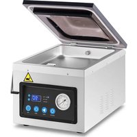
3.1. Device description
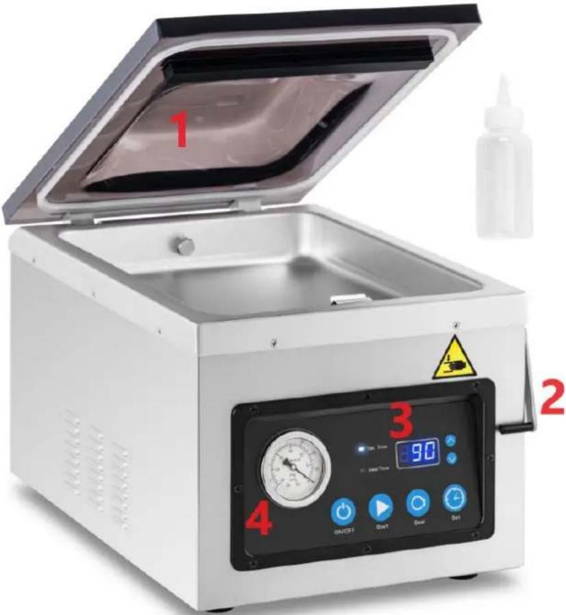
- Cover; 2. Lock; 3. Control panel; 4. Pressure Meter
Control panel:
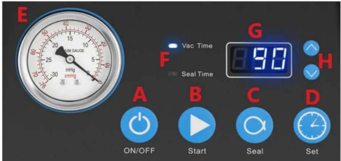
A: ON/OFF button
When the unit is plugged in, the LED display (G) will show "OFF", press the "ON/OFF" button, the LED display (G) will show the time (last setting). Now the unit is ready for operation.
After using the unit, press the "ON/OFF" button before disconnecting the unit from the power supply.
While the unit is running, press the "ON/OFF" button to stop all processes.
B: Automatic Sealing (START) Button
After closing the lid, if the machine cannot operate automatically, press the START button.
The unit will automatically perform extraction and sealing.
C: SEAL button
Press the SEAL button to stop the vacuum sealing cycle and immediately seal the bag to prevent crushing of fragile items.
D: SET button
With the lid open, press the SET button to activate the vacuum seal time settings.
Press the "A" or "V" button to set the time.
E: Pressure indicator
Shows the pressure level inside the vacuum chamber.
F: Indicator light
Vac Time
- vacuum time control light
Seal Time
- seal time control light
The light will come on when:
- When the lid is open, it gives us a signal that the unit is ready for operation.
- When the sealing and sealing is completed or when the on button is pressed.
- If the lid of the machine is not open and the display shows "CLO".
- When the lid is open and the indicator light is on, press the " ∧" or " ∨" button to set the time of each working mode (vacuum time / seal time)
G: Display
Shows the vacuum time / seal time.
When vacuum and seal is finished, or after pressing "ON/OFF" button when the machine is power on, if the vacuum lid is not open, the LED display will show "CLO".
H: Time adjustment button ("Λ" "V")
When the cover is open, press the "A" or "V" button to adjust the time of each setting.
3.2. Preparing for use
APPLIANCE LOCATION
The temperature of environment must not be higher than 40^ C and the relative humidity should be less than 85%. Ensure good ventilation in the room in which the device is being used. There should be at least 10 cm distance between each side of the device and the wall or other objects. The device should always be used when positioned on an even, stable, clean, fireproof and dry surface, and be out of the reach of children and persons with limited mental and sensory functions. Position the device such that you always have access to the power plug. The power cord connected to the appliance must be properly grounded and correspond to the technical details on the product label.
Disassemble the device and all its components and clean them before the first use.
CAUTION! Keep at least 10cm between the unit and walls or other objects to ensure good ventilation of the unit.
Caution! Do not place the unit near steam cookers, dishwashers or ovens.
3.3. Device use
1. Vacuum bag selection
Select the appropriate size vacuum bag. Leave at least 2.5-5cm gap on each side of the bag, this will ensure a better seal of the bag during sealing.
2. Connect the equipment to the power supply
The indicator LED on the control panel will indicate "OFF".
3. Turning the unit on
- Switch on the equipment with the ON/OFF button
- When the appliance lid is open, the LED display will show the vacuum sealing or air extraction time.
- Place the food vacuum bag directly into the vacuum chamber and close the lid.
The appliance will operate automatically.
Caution! When "CLO" appears on the LED display, the unit is in a protected state. In this state, no matter which button is pressed, the appliance will not operate. Open the unit's cover and the unit will return to normal operation.
4. Adjusting/setting the time control
The air extraction time:
Keep the cover open, press the SET button and make sure the air extraction time light is on.
Use the "A" or "V" buttons to increase or decrease the air extraction time. For the first air extraction test, set the time to 30 seconds. Adjust the air extraction time to suit your needs. The time range is from 5 to 90 seconds.
Vacuum sealing time:
Hold the lid open, press the SET button and make sure the vacuum seal time indicator light is on.
Use the "A" or "V" buttons to increase or decrease the vacuum seal time.
For the first air extraction test, set the time to 5 seconds. Adjust the vacuum sealing time to suit your needs.
The time range is from 0 to 6 seconds.
Caution! All time adjustments, must be done with the appliance switched on and the appliance lid open.
5. Placing the bag
- Keep the bag containing the liquid below the height of the sealing bar
- Insert the bag into the vacuum chamber and make sure that the opening of the bag extends beyond the sealing bar
Caution! The entire bag, including the holes, must be inside the vacuum chamber.
6. Suction and vacuum sealing process
- Close the lid of the appliance. The appliance automatically performs air extraction and vacuum sealing.
- After closing the lid, the appliance will automatically start the air extraction and vacuum sealing process, the number on the LED display will count down from the set value (air extraction time, then vacuum sealing time) to 0.
- The air is extracted from the bag. You may notice that the bag is tightening around the product.
- When the machine beeps, the machine cycle is complete.
7. Checking
After each sealing operation, check that the sealing has been done correctly. If there are leaks or creases in the sealing area, extend the sealing time by 5 seconds and repeat the cycle. The welding spot should be clean.
Restoring the factory settings
When the machine is on and OFF appears on the LED display, press the SEAL+SET button simultaneously for 3 seconds. When the unit beeps and displays rS, this indicates that the reset to default settings has been successfully completed.
3.4. Cleaning and maintenance
a) Always unplug the device before cleaning or putting it away.
b) Use only non-corrosive cleaners to clean the surface.
c) Use only mild, food-safe detergents to wash the device.
d) After cleaning the device, all parts should be dried completely before using it again.
e) Store the unit in a dry, cool place, free from moisture and direct exposure to sunlight.
f) Do not spray the device with a water jet or submerge it in water.
g) Do not allow water to get inside the device through vents in the housing of the device.
h) Clean the vents with a brush and compressed air.
i) The device must be regularly inspected to check its technical efficiency and spot any damage.
j) Use a soft, damp cloth for cleaning.
k) Do not use sharp and/or metal objects for cleaning (e.g. a wire brush or a metal spatula) because they may damage the surface material of the appliance.
I) Do not clean the device with an acidic substance, agents of medical purposes, thinners, fuel, oils or other chemical substances because it may damage the device.
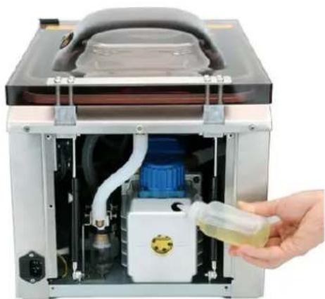
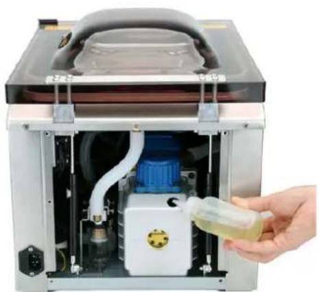
3.4.1. Filling / draining oil from the pump
The pump should be filled with oil when:
1) When using the unit for the first time, oil must be poured into the pump. After the first 25 hours of operation, the oil should be topped up again.
2) When the volume of oil in the pump is below the lowest level, it should be topped up.
3) The performance of the machine seriously deteriorates - check the oil level and top up if necessary.
4) After 60 hours of operation or after 6 months of use, the machine should be filled with oil.
Steps for filling with oil:
1) Use a screwdriver to open the rear cover.
2) Unscrew the cap.
3) Fill the pump with oil using an oil bottle until the oil level in the pump reaches 1/2\~3/4.
4) Tighten the nut.
5) Reinstall the rear cover
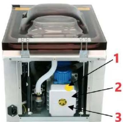
1 - Oil filler cap; 2 - Oil pump; 3 - Oil level gauge

natural_image
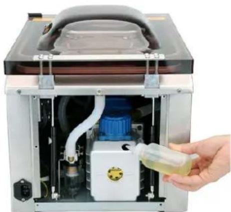
Interior view of a stainless steel water heater with a hand holding a small container (no visible text or symbols)Steps for draining the oil:
1) Prepare a container and place it directly under the oil drain hole.
2) Using a spanner, unscrew the cap counterclockwise and the oil will begin to drain.
3) Once all the oil has drained, tighten the cap.

natural_image
Two views of a mechanical or electronic device showing internal components and mounting holes (no text or symbols visible)1 - Screw Cap; 2 - Spanner

Ensure that the unit is well ventilated. Inhaling gas (which may contain oil residues) escaping from the top during operation can be harmful to human health.
The drained oil must be taken care of in accordance with environmental regulations.
When you have finished filling with oil, make sure that the unit is placed in its normal position. Do not tip it over or allow it to lie on its side.
Troubleshooting
| Error code | Causes | Troubleshooting |
| E01 | When the machine is vacuuming for some time, the pressure switch doesn’t close. | Check if the lid is closed tight.Check if the gasket is installed in right position.Check if the pump is working or not.Check the pressure switch system is in normal working or not (hose, pressure switch and 10P data cord) |
| E02 | When the machine goes into sealing mode, the micro switch doesn’t close. | Check if the lid is closed tight.Check if the micro switch system is in normal working or not (GAS1 cable, micro switch, 10P data cord) |
| LP | Machine loses power during the working. | Check the power supply.Check the power supply system of machine (power cord, 10P data cord) |
DISPOSING OF USED DEVICES:
Do not dispose of this device in municipal waste systems. Hand it over to an electric and electrical device recycling and collection point. Check the symbol on the product, instruction manual and packaging. The plastics used to construct the device can be recycled in accordance with their markings. By choosing to recycle you are making a significant contribution to the protection of our environment.
Contact local authorities for information on your local recycling facility.

natural_image
Interior view of a laboratory apparatus with a hand holding a test tube containing yellow liquid, no visible text or symbols.Kroki spuszczania oleju:
natural_image
Metallic electronic component with mounting holes and a black circular component, no visible text or symbols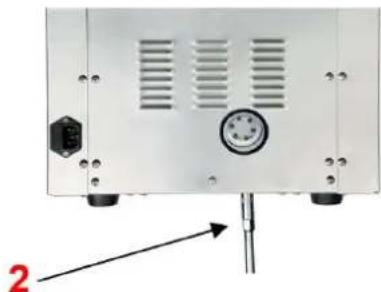
natural_image
Front view of a white electronic device rear panel with ventilation slots and a central control knob (no visible text or symbols)natural_image
Interior view of a stainless steel water heater with a hand pouring liquid into it (no visible text or symbols)natural_image
Two views of a mechanical or electronic device casing with labeled components (1 and 2), showing internal components and mounting holes (no text or symbols beyond labels)natural_image
Interior view of a laboratory apparatus with a hand holding a clear plastic bottle containing a yellow liquid, no visible text or symbols.natural_image
Metallic electronic component with mounting holes and a highlighted circular feature (no text or symbols)
natural_image
Back view of a white electronic device with ventilation slots and a central control knob, no visible text or symbols
natural_image
Interior view of a laboratory apparatus with a hand holding a small transparent bottle containing a yellow liquid, no visible text or symbols.natural_image
Metallic electronic component with mounting holes and a black circular component, no visible text or symbols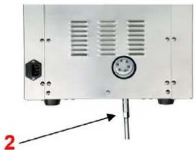
natural_image
Back view of a white electronic device with ventilation slots and a central dial (no text or symbols visible)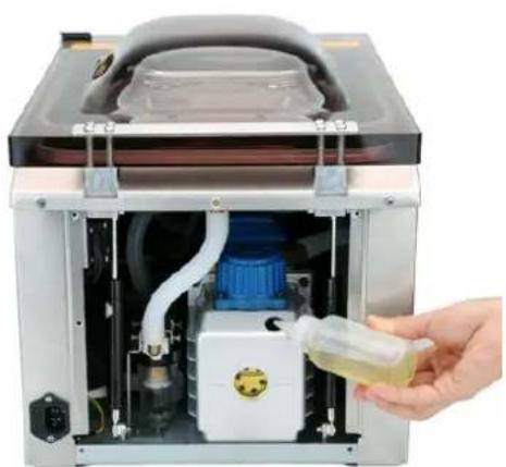
natural_image
Interior view of a laboratory apparatus with a hand holding a small container containing yellow liquid, no visible text or symbols.natural_image
Two views of a metallic electronic device showing internal components and mounting holes (no text or symbols visible)natural_image
Interior view of a stainless steel water heater with a hand pouring liquid into the chamber (no visible text or symbols)natural_image
Metallic electronic component with two circular holes and mounting holes, no visible text or symbols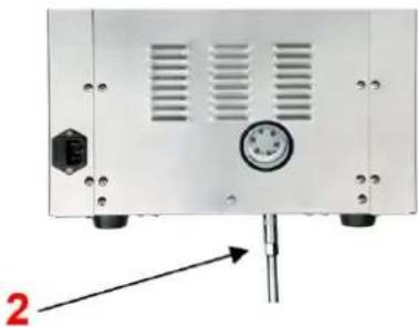
natural_image
Front view of a white electronic device rear panel with ventilation grilles and a pressure gauge, mounted on a pole (no visible text or symbols)APPARATETS PLACERING
1 - Oliepåfyldningsdæksel; 2 - Oliepumpe; 3 - Oliestandsmåler

natural_image
Interior view of a stainless steel water heater with a hand holding a small container (no visible text or symbols)natural_image
Interior view of a stainless steel water heater with a hand pouring liquid into it (no visible text or symbols)natural_image
Two views of a mechanical or electronic device showing internal components and mounting holes (no text or symbols visible)PLAATS VAN HET APPARAAT
1 - Olievuldop; 2 - Oliepomp; 3 - Oliepeilmeter
natural_image
Interior view of a stainless steel water heater with a hand pouring liquid into the chamber (no visible text or symbols)natural_image
Two views of a mechanical or electronic device showing front and side views with labeled components (no text or symbols present)1 – Schroefdop; 2 – Sleutel

OBS! Varm overflate, fare for forbrenning!
1 - Oljepåfyllingslokk; 2 - Oljepumpe; 3 - Oljenivämåler
natural_image
Interior view of a stainless steel water heater with internal components and a hand holding a small container (no visible text or symbols)natural_image
Technical diagram showing two views of a mechanical or electronic component with labeled parts (1 and 2), no readable text or symbols present.APPARATENS PLACERING
natural_image
Interior view of a stainless steel water heater with a hand holding a small container (no visible text or symbols)natural_image
Technical diagram showing two views of a mechanical or electronic component with labeled parts (1 and 2), no readable text or symbols present.1 - Skruvlock; 2 - Nyckel

natural_image
Interior view of a stainless steel water heater with a hand pouring liquid into the chamber (no visible text or symbols)natural_image
Two views of an electronic device casing showing internal components and mounting holes (no text or symbols visible)1 – Tampa de Rosca; 2 – Chave inglesa

1 - uzáver plniaceho hrdla oleja; 2 - Olejové čerpadlo; 3 - Ukazovatel' hladiny oleja
natural_image
Interior view of a stainless steel water heater with a hand pouring liquid into a blue tank (no visible text or symbols)Kroky na vypustenie oleja:
1) Pripravte si nádobu a umiestnite ju priamo pod vypúšťací otvor oleja.
natural_image
Two views of a mechanical or electronic device showing internal components and mounting holes (no text or symbols visible)For the disposal of the device please consider and act according to the national and local rules and regulations.
CONTACT
expondo Polska sp. z o.o. sp. k.
- General description
- DO NOT USE THE DEVICE UNLESS YOU HAVE THOROUGHLY READ AND UNDERSTOOD THIS USER MANUAL.
- Legend
- Usage safety
- Electrical safety
- Safety in the workplace
- Personal safety
- Safe device use
- Use guidelines
- Device description
- Control panel:
- A: ON/OFF button
- B: Automatic Sealing (START) Button
- C: SEAL button
- D: SET button
- E: Pressure indicator
- F: Indicator light
- Vac Time
- Seal Time
- G: Display
- H: Time adjustment button ("Λ" "V")
- Preparing for use
- APPLIANCE LOCATION
- Device use
- Vacuum bag selection
- Connect the equipment to the power supply
- Turning the unit on
- Adjusting/setting the time control
- Placing the bag
- Suction and vacuum sealing process
- Checking
- Restoring the factory settings
- Cleaning and maintenance
- Filling / draining oil from the pump
- DISPOSING OF USED DEVICES:
- Kroki spuszczania oleju:
- APPARATETS PLACERING
- PLAATS VAN HET APPARAAT
- APPARATENS PLACERING
- CONTACT
Brand : Royal Catering
Model : RCVG-47-1
Category : Vacuum packaging machines