DCS778 - Saw DEWALT - Free user manual and instructions
Find the device manual for free DCS778 DEWALT in PDF.

User questions about DCS778 DEWALT
0 question about this device. Answer the ones you know or ask your own.
Ask a new question about this device
Download the instructions for your Saw in PDF format for free! Find your manual DCS778 - DEWALT and take your electronic device back in hand. On this page are published all the documents necessary for the use of your device. DCS778 by DEWALT.
USER MANUAL DCS778 DEWALT
English (original instructions) 28
You have chosen a DeWALT tool. Years of experience, thorough product development and innovation make DeWALT one of the most reliable partners for professional power tool users.
Technical Data
| DCS778 | ||
| Voltage V | pc | 54 |
| Type 1 | ||
| XPS™ Yes | ||
| Blade diameter mm 250 | ||
| Blade bore mm 30 | ||
| Max. blade speed min | -1 | 4300 |
| Mitre (max. positions) left and right 50° | ||
| Bevel (max. positions) left 48° | ||
| Compound litre bevel 45° | ||
| militre 45° | ||
| Capacities | ||
| cross-cut 90° mm 85 x 305 | ||
| mitre 45° mm 85 x 215 | ||
| mitre 48° mm 85 x 204 | ||
| bevel 45° mm 58 x 305 | ||
| bevel 48° mm 54 x 305 | ||
| Overall dimensions | mm | 465 x 615 x 390 |
| Weight (without battery) | kg 15.8 | |
| Noise values and/or vibration values according to EN61029: | ||
| LPA (sound pressure) | dB(A) | 91 |
| LWA (acoustic power) | dB(A) | 100 |
| K (acoustic power uncertainty) | dB(A) | 3 |
The vibration and/or noise emission level given in this information sheet has been measured in accordance with a standardised test given in EN61029 and may be used to compare one tool with another. It may be used for a preliminary assessment of exposure.

WARNING: The declared vibration and/or noise emission level
represents the main applications of the tool. However if the tool is used for different applications, with different accessories or poorly maintained, the vibration and/or noise emission may differ. This may significantly increase the exposure level over the total working period. An estimation of the level of exposure to vibration and/or noise should also take into account the times when the tool is switched off or when it is running but not actually doing the job. This may significantly reduce the exposure level over the total working period. Identify additional safety measures to protect the operator from the effects of vibration and/or noise such as: maintain the tool and the accessories, keep the hands warm (relevant for vibration), organisation of work patterns.
EC-Declaration of Conformity
Machinery Directive

Cordless Cross-cut Mitre Saw
DCS778
DrWALT declares that these products described under Technical Data are in compliance with:
2006/42/EC,EN61029-1:2009 + A11:2010,EN61029-2-9:2012 + A11:2013.
These products also comply with Directive, 2014/30/EU and 2011/65/EU. For more information, please contact DrWALT at the following address or refer to the back of the manual.
The undersigned is responsible for compilation of the technical file and makes this declaration on behalf of DrWALT.

Markus Rompei
Vice President of Engineering, PTE-Europe
DrWALT, Richard-Klinger-StraBe 11
D-65510, Idstein, Germany
20.02.2019

WARNING: To reduce the risk of injury, read the instruction manual.
Safety Instructions

WARNING: Read all safety warnings and all instructions. Failure
to follow the warnings and instructions may result in electric shock, fire and/or serious injury.
SAVE ALL WARNING AND INSTRUCTIONS FOR FUTURE REFERENCE
General Safety Rules
- Keep work area clear.
Cluttered areas and benches invite injuries.
- Consider work area environment.
Do not expose the tool to rain. Do not use the tool in damp or wet conditions. Keep the work area well lit (250-300 Lux). Do not use the tool where there is a risk of causing fire or explosion, e.g., in the presence of flammable liquids and gases. Work area should be well ventilated.
- Guard against electric shock.
Avoid body contact with earthed surfaces (e.g., pipes, radiators, cookers and refrigerators). When using the tool under extreme conditions (e.g., high humidity, when metal swarf is being produced, etc.), electric safety can be improved by inserting an isolating transformer or a (FI) earth-leakage circuit-breaker.
- Keep other persons away.
Do not let persons, especially children, not involved in the work, touch the tool or the battery and keep them away from the work area.
- Store idle tools.
When not in use, tools must be stored in a dry place and locked up securely, out of reach of children.
- Do not force the tool.
It will do the job better and safer at the rate to which it was intended.
- Use the right tool.
Do not force small tools to do the job of a heavy duty tool. Do not
| Batteries Chargers/Charge | Times (Minutes) | ||||||||||
| Cat # V | DC | Ah Weight (kg) | DCB104 DCB107 DCB112 DCB113 DCB115 DCB118 DCB132 DCB119 | ||||||||
| DCB546 | 18/54 | 6.0/2.0 | 1.05 60 270 | 170 140 90 | 60 90 X | ||||||
| DCB547 | 18/54 | 9.0/3.0 | 1.46 | 75* | 420 | 270 | 220 | 135* | 75* | 135* | X |
| DCB548 | 18/54 | 12.0/4.0 | 1.44 | 120 | 540 | 350 | 300 | 180 | 120 | 180 | X |
| DCB181 | 18 | 1.5 | 0.35 | 22 | 70 | 45 | 35 | 22 | 22 | 22 | 45 |
| DCB182 | 18 | 4.0 | 0.61 | 60/40** | 185 | 120 | 100 | 60 | 60/40** | 60 | 120 |
| DCB183/B | 18 | 2.0 | 0.40 | 30 | 90 | 60 | 50 | 30 | 30 | 30 | 60 |
| DCB184/B | 18 | 5.0 | 0.62 | 75/50** | 240 | 150 | 120 | 75 | 75/50** | 75 | 150 |
| DCB185 | 18 | 1.3 | 0.35 | 22 | 60 | 40 | 30 | 22 | 22 | 22 | X |
| DCB187 | 18 | 3.0 | 0.54 | 45 | 140 | 90 | 70 | 45 | 45 | 45 | 90 |
| DCB189 | 18 4.0 0.54 60 185 120 100 60 | 60 60 120 | |||||||||
*Date code 201811475B or later
**Date code 201536 or later
use tools for purposes not intended; for example do not use circular saws to cut tree limbs or logs.
- Dress properly.
Do not wear loose clothing or jewellery, as these can be caught in moving parts. Non-skid footwear is recommended when working outdoors. Wear protective hair covering to contain long hair.
- Use protective equipment.
Always use safety glasses. Use a face or dust mask if working operations create dust or flying particles. If these particles might be considerably hot, also wear a heat-resistant apron. Wear ear protection at all times. Wear a safety helmet at all times.
- Connect dust extraction equipment.
If devices are provided for the connection of dust extraction and collecting equipment, ensure these are connected and properly used.
- Secure work.
Where possible use clamps or a vice to hold the work. It is safer than using your hand and it frees both hands to operate the tool.
- Do not overreach.
Keep proper footing and balance at all times.
- Maintain tools with care.
Keep cutting tools sharp and clean for better and safer performance. Follow instructions for lubricating and changing accessories. Inspect tools periodically and if damaged have them repaired by an authorized service facility. Keep handles and switches dry, clean and free from oil and grease.
- Disconnect tools.
When not in use, before servicing and when changing accessories such as blades, bits and cutters, disconnect tools from the power supply.
- Remove adjusting keys and wrenches.
Form the habit of checking to see that adjusting keys and wrenches are removed from the tool before operating the tool.
- Avoid unintentional starting.
Do not carry the tool with a finger on the switch. Be sure that the tool is in the "off" position before plugging in.
- Stay alert.
Watch what you are doing. Use common sense. Do not operate the tool when you are tired or under the influence of drugs or alcohol.
- Check for damaged parts.
Before use, carefully check the machine to determine that it will operate properly and perform its intended function. Check for alignment of moving parts, binding of moving parts, breakage of parts, mounting and any other conditions that may affect its operation. A guard or other part that is damaged should be properly repaired or replaced by an authorized service centre unless otherwise indicated in this Instruction manual. Have defective switches replaced by an authorized service centre.
Do not use the tool if the switch does not turn it on and off.
Never attempt any repairs yourself.

ING! The use of any accessory or attachment or performance operation with this tool other than those recommended in this ion manual may present a risk of personal injury.
- Have your tool repaired by a qualified person.
This electric tool complies relevant safety rules. Repairs should only be carried out by qualified persons using original spare parts; otherwise this may result in considerable danger to the user.
Additional Safety Rules for Mitre Saws
- Do not use the saw to cut other materials than those recommended by the manufacturer.
- Do not operate the machine without guards in position, or if guards do not function or are not maintained properly.
- Ensure that the arm is securely fixed when performing bevel cuts.
- Keep the floor area around the machine level, well-maintained and free of loose materials, e.g., chips and cut-offs.
- Select the correct blade for the material to be cut.
- Use correctly sharpened saw blades. Observe the maximum speed mark on the saw blade.
- Make sure all locking knobs and clamp handles are tight before starting any operation.
- Never place either hand in the blade area when the saw is connected to the electrical power source.
- Never attempt to stop a machine in motion rapidly by jamming a tool or other means against the blade; serious accidents can occur.
- Before using any accessory consult the instruction manual. The improper use of an accessory can cause damage.
- Use a holder or wear gloves when handling a saw blade or rough material.
- Ensure that the saw blade is mounted correctly before use.
Make sure that the blade rotates in the correct direction. - Do not use blades of larger or smaller diameter than recommended. For the proper blade rating refer to the technical data. Use only the blades specified in this manual, complying with EN847-1.
- Consider applying specially designed noise-reduction blades.
- Do not use HIGH SPEED STEEL blades.
- Do not use cracked or damaged saw blades.
Do not use any abrasive or diamond discs. - Use only saw blades where the marked speed is at least equal to the speed marked on the saw.
- Never use your saw without the kerf plate.
- Raise the blade from the kerf in the workpiece prior to releasing the switch.
Before each cut ensure that the machine is stable. - Do not wedge anything against the fan to hold the motor shaft.
EnGLIsh
- The blade guard on your saw will open when the guard release lever is pushed.
- Never raise the blade guard manually unless the saw is switched off. The guard can be raised by hand when installing or removing saw blades or for inspection of the saw.
- Check periodically that the motor air slots are clean and free of chips.
- Replace the kerf plate when worn.
- Remove the battery from the machine before carrying out any maintenance work or when changing the blade.
- Never perform any cleaning or maintenance work when the machine is still running and the head is not in the rest position.
- When fitted with LED, no exchange with different type of LED permitted. Repairs shall only be carried out by the manufacturer or an authorized agent.
- Connect the saw to a dust collection device when sawing wood. Always consider factors which influence exposure of dust such as:
-type of material to be machined (chip board produces more dust than wood);
- sharpness of the saw blade;
- correct adjustment of the saw blade,
-dust extractor with air velocity not less than 20m / s
Ensure that the local extraction as well as hoods, baffles and chutes are properly adjusted.
- Please be aware of the following factors influencing exposure to noise:
-use saw blades designed to reduce the emitted noise;
-use only well sharpened saw blades;
Machine maintenance shall be conducted periodically;
- Provide adequate general or localized lighting;
- Ensure the operator is adequately trained in the use, adjustment and operation of the machine;
- Ensure that any spacers and spindle rings are suitable for the purpose as stated in this manual.
- Refrain from removing any cut-offs or other parts of the workpiece from the cutting area while the machine is running and the saw head is not in the rest position
- Never cut workpieces shorter than 150mm
- Without additional support the machine is designed to accept the maximum workpiece size of:
Height 60 mm by width 216 mm by length 500 mm
-
Longer workpieces need to be supported by suitable additional table, e.g. DE7023. Always clamp the workpiece safely.
-
In case of an accident or machine failure, immediately turn the machine off and disconnect machine from the power source.
Report the failure and mark the machine in suitable form to prevent other people from using the defective machine. - When the saw blade is blocked due to abnormal feed force during cutting, turn the machine off and disconnect it from power supply. Remove the workpiece and ensure that the saw blade runs free. Turn the machine on and start new cutting operation with reduced feed force.
- Never cut light alloy, especially magnesium.
- Whenever the situation allows, mount the machine to a bench using bolts with a diameter of 8 mm and 80 mm in length.
Residual Risks
The following risks are inherent to the use of saws:
injuries caused by touching the rotating parts
In spite of the application of the relevant safety regulations and the implementation of safety devices, certain residual risks cannot be avoided.
These are:
Impairment of hearing.
- Risk of accidents caused by the uncovered parts of the rotating saw blade.
- Risk of injury when changing the unprotected saw blade.
- Risk of squeezing fingers when opening the guards.
- Health hazards caused by breathing dust developed when sawing wood, especially oak, beech and MDF.
The following factors increase the risk of breathing problems:
- No dust extractor connected when sawing wood
Insufficient dust extraction caused by uncleaned exhaust filters
SAVE THESE INSTRUCTIONS
Chargers
DeWALT chargers require no adjustment and are designed to be as easy as possible to operate.
Electrical Safety
The electric motor has been designed for one voltage only. Always check that the battery pack voltage corresponds to the voltage on the rating plate. Also make sure that the voltage of your charger corresponds to that of your mains.

Your DrWALT charger is double insulated in accordance with EN60335; therefore no earth wire is required.
If the supply cord is damaged, it must be replaced only by DrWALT or an authorised service organisation.
Mains Plug Replacement
(U.K. & Ireland Only)
If a new mains plug needs to be fitted:
- Safely dispose of the old plug.
- Connect the brown lead to the live terminal in the plug.
- Connect the blue lead to the neutral terminal.

ING: No connection is to be made to the earth terminal.
Follow the fitting instructions supplied with good quality plugs.
Recommended fuse: 3 A.
Using an Extension Cable
An extension cord should not be used unless absolutely necessary. Use an approved extension cable suitable for the power input of your charger (see
Technical Data). The minimum conductor size is 1mm^2 the maximum length is 30m
When using a cable reel, always unwind the cable completely.
Important Safety Instructions for All Battery Chargers
SAVE THESE INSTRUCTIONS: This manual contains important safety and operating instructions for compatible battery chargers (refer to Technical Data).
- Before using charger, read all instructions and cautionary markings on charger, battery pack, and product using battery pack.

ING: Shock hazard. Do not allow any liquid to get inside. Electric shock may result.

ING: We recommend the use of a residual current device with a 10 mA current rating of 30mA or less.

ON: Burn hazard. To reduce the risk of injury, charge only T rechargeable batteries. Other types of batteries may burst g personal injury and damage.

ON: Children should be supervised to ensure that they do not with the appliance.
NOTICE: Under certain conditions, with the charger plugged into the power supply, the exposed charging contacts inside the charger can be shorted by foreign material. Foreign materials of a conductive nature such as, but not limited to, steel wool, aluminum foil or any buildup of metallic particles should be kept away from charger cavities. Always unplug the charger from the power supply when there is no battery pack in the cavity. Unplug charger before attempting to clean
DO NOT attempt to charge the battery pack with any chargers other than the ones in this manual. The charger and battery pack are specifically designed to work together.
These chargers are not intended for any uses other than charging DeWALT rechargeable batteries. Any other uses may result in risk of fire, electric shock or electrocution.
- Do not expose charger to rain or snow.
- Pull by plug rather than cord when disconnecting charger. This will reduce risk of damage to electric plug and cord.
- Make sure that cord is located so that it will not be stepped on, tripped over, or otherwise subjected to damage or stress.
- Do not use an extension cord unless it is absolutely necessary. Use of improper extension cord could result in risk of fire, electric shock, or electrocution.
- Do not place any object on top of charger or place the charger on a soft surface that might block the ventilation slots and result in excessive internal heat. Place the charger in a position away from any heat source. The charger is ventilated through slots in the top and the bottom of the housing.
- Do not operate charger with damaged cord or plug—have them replaced immediately.
- Do not operate charger if it has received a sharp blow, been dropped, or otherwise damaged in any way. Take it to an authorised service centre.
- Do not disassemble charger; take it to an authorised service centre when service or repair is required. Incorrect reassembly may result in a risk of electric shock, electrocution or fire.
- In case of damaged power supply cord the supply cord must be replaced immediately by the manufacturer, its service agent or similar qualified person to prevent any hazard.
- Disconnect the charger from the outlet before attempting any cleaning. This will reduce the risk of electric shock. Removing the battery pack will not reduce this risk.
NEVER attempt to connect two chargers together. - The charger is designed to operate on standard 230V household electrical power. Do not attempt to use it on any other voltage. This does not apply to the vehicular charger.
Charging a Battery (Fig. C)
- Plug the charger into an appropriate outlet before inserting battery pack.
- Insert the battery pack 26 into the charger, making sure the battery pack is fully seated in the charger. The red (charging) light will blink repeatedly indicating that the charging process has started.
- The completion of charge will be indicated by the red light remaining ON continuously. The battery pack is fully charged and may be used at this time or left in the charger. To remove the battery pack from the charger, push the battery release button 27 on the battery pack.
NOTE: To ensure maximum performance and life of lithium-ion battery packs, charge the battery pack fully before first use.
Charger Operation
Refer to the indicators below for the charge status of the battery pack.
| Charge Indicators | |
| Charging | - - - - - |
| Fully Charged | - - - - - |
| Hot/Cold Pack Delay* | - - - - - |
- The red light will continue to blink, but a yellow indicator light will be illuminated during this operation. Once the battery pack has reached an appropriate temperature, the yellow light will turn off and the charger will resume the charging procedure.
The compatible charger(s) will not charge a faulty battery pack. The charger will indicate faulty battery by refusing to light.
NOTE: This could also mean a problem with a charger.
If the charger indicates a problem, take the charger and battery pack to be tested at an authorised service centre.
Hot/Cold Pack Delay
When the charger detects a battery pack that is too hot or too cold, it automatically starts a Hot/Cold Pack Delay, suspending charging until the battery pack has reached an appropriate temperature. The charger then automatically switches to the pack charging mode. This feature ensures maximum battery pack life.
A cold battery pack will charge at a slower rate than a warm battery pack. The battery pack will charge at that slower rate throughout the entire charging cycle and will not return to maximum charge rate even if the battery pack warms.
The DCB118 charger is equipped with an internal fan designed to cool the battery pack. The fan will turn on automatically when the battery pack needs to be cooled. Never operate the charger if the fan does not operate properly or if ventilation slots are blocked. Do not permit foreign objects to enter the interior of the charger.
Electronic Protection System
XR Li-Ion tools are designed with an Electronic Protection System that will protect the battery pack against overloading, overheating or deep discharge.
The tool will automatically turn off if the Electronic Protection System engages. If this occurs, place the lithium-ion battery pack on the charger until it is fully charged.
Wall Mounting
These chargers are designed to be wall mountable or to sit upright on a table or work surface. If wall mounting, locate the charger within reach of an electrical outlet, and away from a corner or other obstructions which may impede air flow. Use the back of the charger as a template for the location of the mounting screws on the wall. Mount the charger securely using drywall screws (purchased separately) at least 25.4mm long with a screw head diameter of 7 - 9mm , screwed into wood to an optimal depth leaving approximately 5.5mm of the screw exposed. Align the slots on the back of the charger with the exposed screws and fully engage them in the slots.
Charger Cleaning Instructions
WARNING: Shock hazard. Disconnect the charger from the AC before cleaning. Dirt and grease may be removed from the exterior of the charger using a cloth or soft non-metallic brush. Do not use water or any cleaning solutions. Never let any liquid get inside the tool; never immerse any part of the tool into a liquid.
Battery Packs
Important Safety Instructions for All Battery Packs
When ordering replacement battery packs, be sure to include catalogue number and voltage.
The battery pack is not fully charged out of the carton. Before using the battery pack and charger, read the safety instructions below. Then follow charging procedures outlined.
READ ALL INSTRUCTIONS
- Do not charge or use battery in explosive atmospheres, such as in the presence of flammable liquids, gases or dust. Inserting or removing the battery from the charger may ignite the dust or fumes.
- Never force battery pack into charger. Do not modify battery pack in any way to fit into a non-compatible charger as battery pack may rupture causing serious personal injury.
- Charge the battery packs only in DrWALT chargers.
DO NOT splash or immerse in water or other liquids.
ENGLISH
- Do not store or use the tool and battery pack in locations where the temperature may reach or exceed 40^ (104 F) (such as outside sheds or metal buildings in summer).
- Do not incinerate the battery pack even if it is severely damaged or is completely worn out. The battery pack can explode in a fire. Toxic fumes and materials are created when lithium-ion battery packs are burned.
- If battery contents come into contact with the skin, immediately wash area with mild soap and water. If battery liquid gets into the eye, rinse water over the open eye for 15 minutes or until irritation ceases. If medical attention is needed, the battery electrolyte is composed of a mixture of liquid organic carbonates and lithium salts.
- Contents of opened battery cells may cause respiratory irritation. Provide fresh air. If symptoms persist, seek medical attention.
WARNING: Burn hazard, Battery liquid may be flammable if exposed to work or flame.
WARNING: Never attempt to open the battery pack for any reason. If a battery pack case is cracked or damaged, do not insert into charger. Do not crush, drop or damage battery pack. Do not use a battery pack or charger that has received a sharp blow, been dropped, run over or damaged in any way (i.e., pierced with a nail, hit with a hammer, stepped on). Electric shock or electrocution may result. Damaged battery packs should be returned to service centre for recycling.
WARNING: Fire hazard. Do not store or carry the battery pack so metal objects can contact exposed battery terminals. For example, do not place the battery pack in aprons, pockets, tool boxes, product kit boxes, drawers, etc., with loose nails, screws, keys, etc.
CAUTION: When not in use, place tool on its side on a stable surface where it will not cause a tripping or falling hazard. Some tools with large battery packs will stand upright on the battery pack but may be easily knocked over.
Transportation
WARNING: Fire hazard. Transporting batteries can possibly cause the battery terminals inadvertently come in contact with conductive materials. When transporting batteries, make sure that the battery terminals are protected and well insulated from materials that could contact them and cause a short circuit.
NOTE: lithium-ion batteries should not be put in checked baggage.
DeWALT batteries comply with all applicable shipping regulations as prescribed by industry and legal standards which include UN Recommendations on the Transport of Dangerous Goods; International Air Transport Association (IATA) Dangerous Goods Regulations, International Maritime Dangerous Goods (IMDG) Regulations, and the European Agreement Concerning The International Carriage of Dangerous Goods by Road (ADR). Lithium-ion cells and batteries have been tested to section 38.3 of the UN Recommendations on the Transport of Dangerous Goods Manual of Tests and Criteria.
In most instances, shipping a DEWALT battery pack will be excepted from being classified as a fully regulated Class 9 Hazardous Material. In general, only shipments containing a lithium-ion battery with an energy rating greater than 100 Watt Hours (Wh) will require being shipped as fully regulated Class 9. All lithium-ion batteries have the Watt Hour rating marked on the pack. Furthermore, due to regulation complexities, DEWALT does not recommend air shipping lithium-ion battery packs alone regardless of Watt Hour rating. Shipments of tools with batteries (combok kits) can be air shipped as excepted if the Watt Hour rating of the battery pack is no greater than 100 Whr.
Regardless of whether a shipment is considered excepted or fully regulated, it is the shipper's responsibility to consult the latest regulations for packaging, labeling/marking and documentation requirements.
The information provided in this section of the manual is provided in good faith and believed to be accurate at the time the document was created. However, no warranty, expressed or implied, is given. It is the buyer's
responsibility to ensure that its activities comply with the applicable regulations.
Transporting the FLEXVOLT™ Battery
The DeWALT FLEXVOLT™ battery has two modes: Use and Transport.
Use Mode: When the FLEXVOLT™ battery stands alone or is in a DeWALT 18V product, it will operate as an 18V battery. When the FLEXVOLT™ battery is in a 54V or a 108V (two 54V batteries) product, it will operate as a 54V battery.
Transport Mode: When the cap is attached to the FLEXVOLT™ battery, the battery is in Transport mode. Keep the cap for shipping.
When in Transport mode, strings of cells are electrically disconnected within the pack resulting in 3 batteries with a lower Watt hour (Wh) rating as compared to 1 battery
with a higher Watt hour rating. This increased quantity of 3 batteries with the lower Watt hour rating can exempt the pack from certain shipping regulations that are imposed upon the higher Watt hour batteries.
For example, the Transport Wh rating might indicate 3 x 36 Wh, meaning 3 batteries of 36 Wh each. The Use Wh rating might indicate 108 Wh (1 battery implied).
Example of Use and Transport Label Marking

Use: 108 Wh
Transport:3x36 Wh
Storage Recommendations
- The best storage place is one that is cool and dry away from direct sunlight and excess heat or cold. For optimum battery performance and life, store battery packs at room temperature when not in use.
- For long storage, it is recommended to store a fully charged battery pack in a cool, dry place out of the charger for optimal results.
NOTE: Battery packs should not be stored completely depleted of charge. The battery pack will need to be recharged before use.
Labels on Charger and Battery Pack
In addition to the pictographs used in this manual, the labels on the charger and the battery pack may show the following pictographs:

Read instruction manual before use.

See Technical Data for charging time.

Do not probe with conductive objects.

Do not charge damaged battery packs.

Do not expose to water.

Have defective cords replaced immediately.

Charge only between 4^ and 40^

Only for indoor use.

Discard the battery pack with due care for the environment.

Charge DrWALT battery packs only with designated DrWALT chargers. Charging battery packs other than the designated DeWALT batteries with a DeWALT charger may make them burst or lead to other dangerous situations.

Do not incinerate the battery pack.

USE (without transport cap). Example: Wh rating indicates 108 Wh (1 battery with 108 Wh).

TRANSPORT (with built-in transport cap). Example: Wh rating indicates 3 x 36 Wh (3 batteries of 36 Wh).
Battery Type
The DCS778 operates on a 54 volt battery pack. These battery packs may be used: DCB546, DCB547, DCB548. Refer to Technical Data for more information.
Package Contents
The package contains:
1 Partly assembled machine
2 hex key (4 mm and 6 mm)
1 250 mm TCT saw blade
1 Material clamp
2 Battery packs (T2 model)
1 Charger (T2 model)
1 Instruction manual
- Check for damage to the tool, parts or accessories which may have occurred during transport.
Take the time to thoroughly read and understand this manual prior to operation.
Markings on Tool
The following pictograms are shown on the tool:

Read instruction manual before use.

Wear ear protection.

Wear eye protection.

Visible radiation. Do not stare into light.

Carrying point
Date Code Position (Fig. B)
The Date Code 57, which also includes the year of manufacture, is printed into the housing.
Example:
2019 XX XX
Description (Fig. A-C, E)
WARNING: Never modify the power tool or any part of it. Damage or personal injury could result.
1 Trigger switch
2 Guard lock-up release lever
3 Operating handle
4 Fixed upper guard
5 Outer flange
6 Blade bolt
7 Lower blade guard
8 Saw blade
9 Sliding fence lock knob
10 Fixed table
11 Kerf plate
12 Mitre arm
13 Mitre latch
14 Rotating table/mitre arm
15 Mitre scale
16 Sliding fence
17 Material clamp
18 Traverse lock
19 Bevel clamp handle
20 Bevel scale
21 Bench mounting holes
22 Lock down button
23 Traverse bars
24 Saw head
25 Hex keys
26 Battery pack
27 Battery pack release button
28 Fuel gauge button
29 Lock off switch
30 Override button
31 Carrying handle (left and right)
32 Inner flange (Fig. E)
33 Dust extraction port
34XPSTMButton
Intended Use
Your D-WALT cordless compact metre saw has been designed for professional cutting wood, wood products, aluminum and plastics. It performs the sawing operations of cross-cutting, bevelling and mitring easily, accurately and safely.
This unit is designed for use with a nominal blade diameter 250 mm carbide tip blade.
DO NOT use under wet conditions or in presence of flammable liquids or gases.
These miter saws are professional power tools.
DO NOT let children come into contact with the tool. Supervision is required when inexperienced operators use this tool.

ING: Do not use the machine for purposes other than intended.
- Young children and the infirm. This appliance is not intended for use by young children or infirm persons without supervision.
- This product is not intended for use by persons (including children) suffering from diminished physical, sensory or mental abilities; lack of experience, knowledge or skills unless they are supervised by a person responsible for their safety. Children should never be left alone with this product.
ASSEMBLY
WARNING: To reduce the risk of serious personal injury, turn machine off and disconnect battery pack before making any adjustments or removing/installing attachments or accessories. An accidental start-up can cause injury.

ING: Use only DwALT battery packs and chargers.
Unpacking
The motor and guards are already assembled onto the base.
Inserting and Removing the Battery Pack from the Tool (Fig. A-C)
NOTE: Make sure your battery pack 26 is fully charged.
To Install the Battery Pack into the Tool
- Align the battery pack 26 with the rails inside the tool's handle (Fig. A).
- Slide it into the handle until the battery pack is firmly seated in the tool and ensure that you hear the lock snap into place.
To Remove the Battery Pack from the Tool
- Press the release button 27 and firmly pull the battery pack out of the tool handle.
- Insert battery pack into the charger as described in the charger section of this manual.
Fuel Gauge Battery Packs (Fig. C)
Some DWALT battery packs include a fuel gauge which consists of three green LED lights that indicate the level of charge remaining in the battery pack.
To actuate the fuel gauge, press and hold the fuel gauge button 28. A combination of the three green LED lights will illuminate designating the level of charge left. When the level of charge in the battery is below the usable limit, the fuel gauge will not illuminate and the battery will need to be recharged.
EnGLlish
NOTE: The fuel gauge is only an indication of the charge left on the battery pack. It does not indicate tool functionality and is subject to variation based on product components, temperature and end-user application.
Bench Mounting (Fig. B, T)
- Holes 21 are provided in all four feet to facilitate bench mounting. Bolts with a diameter of 8mm and 80~mm in length is suggested. Always mount your saw firmly to prevent movement. To enhance the portability, the tool can be mounted to a piece of 12.5mm or thicker plywood which can then be clamped to your work support or moved to other job sites and reclamped.
- When mounting your saw to a piece of plywood, make sure that the mounting screws do not protrude from the bottom of the wood. The plywood must sit flush on the work support. When clamping the saw to any work surface, clamp only on the clamping bosses where the mounting screw holes are located. Clamping at any other point will interfere with the proper operation of the saw.
- To prevent binding and inaccuracy, be sure the mounting surface is not warped or otherwise uneven. If the saw rocks on the surface, place a thin piece of material under one saw foot until the saw is firm on the mounting surface.
Mounting the Saw Blade (Fig. A, D, E)
WARNING: To reduce the risk of injury, turn unit off and connect machine from power source before installing and removing accessories, before adjusting or changing set-ups or when making repairs. Be sure the trigger switch is in the OFF position. An accidental start-up can cause injury.

WARNING: The teeth of a new blade are very sharp and can be dangerous.
WARNING: Be aware the saw blade shall be replaced in the described way only. Only use saw blades as specified under Technical Data; Cat.no.:DT4320 is suggested.
- Insert the 6 mm hex key 25 into the opposite location of the blade shaft and hold it (Fig. D).
- Use second hex key as shown in Figure D as spindle lock.
- Loosen the blade bolt 6 by turning clockwise. Remove the blade bolt and the outer flange 5.
- Press the lower guard lock up release lever 2 to raise the lower blade guard 7 and remove the saw blade 8.
- Install the new saw blade onto the shoulder provided on the inner flange 32 making sure that the teeth at the bottom edge of the blade are pointing towards the fence (away from the operator).
- Replace the outer flange 5, making sure that the location lugs are engaged correctly, one on each side of the motor shaft 36.
- Tighten the blade bolt 6 by turning counterclockwise while holding the 6 mm hex key 25 engaged with your other hand (Fig. D).
ADJUSTMENTS
WARNING: To reduce the risk of serious personal injury, turn off and disconnect battery pack before making any adjustments or removing/installing attachments or accessories. An accidental start-up can cause injury.
Your litre saw was accurately adjusted at the factory. If readjustment due to shipping and handling or any other reason is required, follow the steps below to adjust your saw. Once made, these adjustments should remain accurate.
Adjusting the Traverse Bars for Constant Cutting Depth (Fig. A, B, F, H)
The blade must run at a constant cutting depth along the full length of the table and must not touch the fixed table at the rear of the slot or at the front of the rotating arm. To achieve this, the traverse arms must be perfectly parallel to the table when the saw head is fully depressed.
- Press the lower guard lock up release lever 2 (Fig. A).
- Press the saw head fully to the rear position and measure the height from the rotating table 14 to the bottom of the outer flange 5 (Fig. F).
- Turn the saw head traverse lock 18 (Fig.B).
- Keeping the saw head fully depressed, pull the head to the end of its travel.
- Measure the height indicated in Figure F again. Both values should be identical.
- If adjustment is required, proceed as follows (Fig. H):
a. Loosen the locknut 37 in the bracket 38 and adjust the screw 39 as required, proceeding in small steps.
b. Tighten the locknut 37.
WARNING: Always check that the blade does not touch the table at 1/2 of the slot or at the front of the rotating arm at 90^ vertical and 45^ bevel positions. Do not switch on before having checked this!
Adjusting the Fence (Fig. I)
Turn the sliding fence lock knob 9 counterclockwise to loosen. Move the sliding fence 16 to a position that avoids the blade cuts it, then tighten the fence lock knob by turning clockwise.
Checking and Adjusting the Blade to the Fence (Fig. B, J, K)
- Slacken the litre latch 13.
- Place your thumb on the litre arm 12 and squeeze the litre latch 13 to release the rotating table/mitre arm 14.
- Swing the litre arm until the latch locates it at the 0^ litre position.
- Pull down the head and lock it in this position using the lock down button 22.
- Check that the two 0^ markings 40 on the litre scale 15 are just visible.
-
Place a square 41 against the left side of the fence 16 and blade 8. W P N I N G: Do not touch the tips of the blade teeth with the square.
-
If adjustment is required, proceed as follows:
a. Loosen the screws 42 and move the scale/mitre arm assembly left or right until the blade is at 90^ to the fence as measured with the square (Fig. J).
b. Retighten the screws 42
Checking and Adjusting the Blade to the Table (Fig. L-N)
- Loosen the bevel clamp handle 19 (Fig. L).
- Press the saw head to the right to ensure it is fully vertical and tighten the bevel clamp handle.
-
Place a set square 41 on the table and up against the blade 8 (Fig. M). W R N I N G: Do not touch the tips of the blade teeth with the square.
-
If adjustment is required, proceed as follows:
a. Loosen the bevel clamp handle 19 and turn the vertical position adjustment stop screw 43 in or out until the blade is at 90^ to the table as measured with the square.
b. If the bevel pointer 44 does not indicate zero on the bevel scale 20, loosen the screws 45 that secure the scale and move the scale as necessary.
Checking and Adjusting the Bevel Angle (Fig. A, L, N) The bevel override allows the max. bevel angle to be set at 45^ or 48^ as required.
-
Left = 45°
-Right=48° -
Make sure the override knob 46 is located in the left position.
-
Loosen the bevel clamp handle 19 and move the saw head to the left.
- This is the 45^ bevel position.
- If adjustment is required, turn the stopscrew 47 in or out as necessary until the pointer 44 indicates 45^ .
WARNING: The guide grooves can become clogged with sawdust. Use or some low pressure air to clear the guide grooves.
Prior to Operation
WARNING:
-
All the appropriate saw blade. Do not use excessively worn blades. The maximum rotation speed of the tool must not exceed that of the saw blade.
-
Do not attempt to cut excessively small pieces.
- Allow the blade to cut freely. Do not force.
- Allow the motor to reach full speed before cutting.
Make sure all locking knobs and clamp handles are tight. - Secure the workpiece.
- Although this saw will cut wood and many nonferrous materials, these operating instructions refer to the cutting of wood only. The same guide-lines apply to the other materials. Do not cut ferrous (iron and steel) materials or masonry with this saw! Do not use any abrasive discs!
Make sure to use the kerf plate. Do not operate the machine if the kerf slot is wider than 10 mm. - Placing the workpiece on a piece of wood will increase the capacities to 300 mm.
OPERATION
Instructions for Use
WARNING: Always observe the safety instructions and applicable regulations.
WARNING: To reduce the risk of serious personal injury, turn off and disconnect battery pack before making any adjustments or removing/installing attachments or accessories.
An accidental start-up can cause injury.
The attention of UK users is drawn to the "woodworking machines regulations 1974" and any subsequent amendments.
Ensure the machine is placed to satisfy your ergonomic conditions in terms of table height and stability. The machine site shall be chosen so that the operator has a good overview and enough free surrounding space around the machine that allows handling of the workpiece without any restrictions. To reduce effects of increased vibration, make sure the environment is not too cold, the machine and accessory are well maintained and the workpiece size is suitable for this machine.
Switching On and Off (Fig. A)
The lock off switch 29 located on the the on/off trigger switch 1 must be flipped in order for the saw to turn on.
- To run the tool, flip the lock off switch 29 and press the on/off trigger switch 1.
- To stop the tool, release the trigger switch. The lock off switch will re-engage automatically.
Use of XPS™ LED Worklight System (Fig. A, R)
NOTE: The litre saw must be connected to a power source.
The XPS™ LED Worklight System is activated by engaging the trigger or pressing the XPS™ button 34 on top of the saw housing.
To cut through an existing pencil line on a piece of wood:
-
With the XPS light on, pull down on the operating handle 3 to bring the saw blade close to the wood. The shadow of the blade will appear on the wood.
-
Align the pencil line with the edge of the blade's shadow. You may have to adjust the litre or bevel angles in order to match the pencil line exactly.
Your saw is equipped with a battery fault feature. The XPS™ worklight begins to flash when the battery is near the end of its useful charge, or when the battery is too hot. Charge the battery prior to continuing cutting applications. Refer to Charging A Battery for battery charging instructions.
Body and Hand Position
Proper positioning of your body and hands when operating the mitre saw will make cutting easier, more accurate and safer.
WARNING:
-
Never place your hands near the cutting area.
-
Place your hands no closer than 150 mm from the blade.
- Hold the workpiece tightly to the table and the fence when cutting. Keep your hands in position until the switch has been released and the blade has completely stopped.
Always make dry runs (without power) before finish cuts so that you can check the path of the blade.
Do not cross your hands.
- Keep both feet firmly on the floor and maintain proper balance.
- As you move the saw arm left and right, follow it and stand slightly to the side of the saw blade.
Basic Saw Cuts
Vertical Straight Cross Cut (Fig. A, O)
NOTE: Use 250 mm saw blades with 30 mm arbor holes to obtain the desired cutting capacities.
- Slacken the mitre latch 13 and subsequently lift it up.
- Engage the litre latch 13 at the 0^ position and fasten the litre latch.
- Place the wood to be cut against the fence 16
- Take hold of the carrying handle 3 and press the guard lock up release lever 2 to release the guard. Extend head of the saw all the way out.
- Press the trigger switch 1 to start the motor.
- Depress the head to allow the blade to cut through the timber and enter the plastic kerf plate 11.
- When the head is fully depressed, slowly push it back across to complete the cut.
- After completing the cut, release the switch and wait for the saw blade to come to a complete standstill before returning the head to its upper rest position.
WARNING:
lower blade guard is designed to close quickly when the lever 2 is released. If it does not close within 1 second, have the saw serviced by an authorized DrWALT repair agent.
Vertical Mitre Cross-cut (Fig. A, P)
- Squeeze the litre latch 13. Move the arm left or right to the required angle.
- The litre latch will automatically locate at 0^ , 15^ , 22.5^ , 31.62^ , 45^ and 50^ both left and right. If any intermediate angle is required hold the head firmly and lock by fastening the litre latch.
- Always ensure that the mitre lock lever is locked tightly before cutting.
- Proceed as for a vertical straight cross-cut.
WARNING: When mitrung the end of a piece of wood small off-cut, position the wood to ensure that the off-cut is to the side of the blade with the greater angle to the fence, i.e.:
left litre, off-cut to the right
right mitre, off-cut to the left
Performing a Sliding Cut (Fig. A, B, R)
- Turn the saw head traverse lock 18 to loosen.
ENGLish
- Push down the saw head 24, pull out the lock-down button 22 and let the saw head rise to it's highest position.
- Place the wood to be cut against the sliding fence 16 and secure it with the material clamp 17.
- Lower the saw head then pull it to the end of its travel.
- Press the guard lock-up release lever 2 to release the guard. Press the trigger switch 1 to start the motor.
- Totally depress the head to allow the blade to cut through the timber and push the head back to complete the cut.
- After completing the cut, release the switch and wait for the saw blade to come to a complete standstill before returning the head to its upper rest position.
WARNING: Remember to lock the saw head in the rear position when cutting cuts are finished.
Bevel Cross-cuts (Fig. L, Q)
Bevel angles can be set from 0^ to 48^ to the left. Bevels up to 45^ can be cut with the litre arm set between zero and a maximum of 45^ litre position right or left.
- Loosen the bevel clamp handle 19 and set the bevel as desired.
- Set the override button 30 if required.
- Hold the head firmly and do not allow it to fall.
- Tighten the bevel clamp handle 19 firmly.
- Proceed as for a vertical straight cross-cut.
Quality of Cut
The smoothness of any cut depends on a number of variables, i.e. the material being cut. When smoothest cuts are desired for moulding and other precision work, a sharp (60-tooth carbide) blade and a slower, even cutting rate will produce the desired results.
WARNING: Ensure that the material does not creep while cutting; clean it securely in place. Always let the blade come to a full stop before raising the arm. If small fibres of wood still split out at the rear of the workpiece, stick a piece of masking tape on the wood where the cut will be made. Saw through the tape and carefully remove tape when finished.
Cutting Non-Ferrous Metals
When cutting non-ferrous metals, the machine is only to be used to perform vertical straight and litre cross-cuts in the litre saw mode. We recommend that bevel and compound litre cuts should not be performed in non-ferrous metals. The machine is not to be used for cutting ferrous metals.
Always use a material clamp when cutting non-ferrous metals. Make sure that the workpiece is clamped securely.
- Only apply saw blades that are qualified for cutting non-ferrous metals.
- When using lubricants, only apply wax or separation spray. Do not use emulsions or similar fluids.
Clamping the Workpiece (Fig. U)
WARNING: Always use a material clamp.
For best results use the material clamp 17 made for use with your saw.
To Install clamp
- Insert it into the hole behind the fence. The clamp 17 should be facing toward the back of the metre saw. Ensure the groove on the clamp rod is fully inserted into the base of the metre saw. If the groove is visible, the clamp will not be secure.
- Rotate the clamp 180^ toward the front of the litre saw.
- Loosen the knob to adjust the clamp up or down, then use the fine adjust knob to firmly clamp the workpiece.
NOTE: Place the clamp on the right side of the base when beveling. ALWAYS MAKE DRY RUNS (UNPOWERED) BEFORE FINISH CUTS TO CHECK
THE PATH OF THE BLADE. ENSURE THE CLAMP DOES NOT INTERFERE WITH THE ACTION OF THE SAW OR GUARDS.
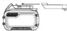
Compound Mitre (Fig. S, T)
This cut is a combination of a litre and a bevel cut. This is the type of cut used to make frames or boxes with slanting sides like the one shown in Figure S.
WARNING: if the cutting angle varies from cut to cut, check that the bevel clamp handle and the mitre clamping knob are securely tightened. These must be tightened after making any changes in bevel or mitre.
WARNING: The saw must be fixed on a base support when performing compound cuts to prevent tip over. Refer to Bench
Mounting.
- The chart shown below will assist you in selecting the proper bevel and litre settings for common compound litre cuts.
To use the chart, select the desired angle "A" (Fig. S) of your project and locate that angle on the appropriate arc in the chart. From that point follow the chart straight down to find the correct bevel angle and straight across to find the correct metre angle.
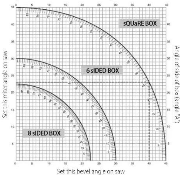
- Set your saw to the prescribed angles and make a few trial cuts.
- Practice fitting the cut pieces together. Example: To make a four-sided box with 25^ exterior angles (angle "A") (Fig. S), use the upper right arc. Find 25^ on the arc scale. Follow the horizontal intersecting line to either side to get the mitre angle setting on the saw (23^) . Likewise follow the vertical intersecting line to the top or bottom to get the bevel angle setting on the saw (40^) . Always try cuts on a few scrap pieces of wood to verify the settings on the saw.
WARNING: Never exceed the compound litre limits of 45^ bevel with 10 ml or right litre.

Dust Extraction (Fig. A, G)
WARNING: Whenever possible, connect a dust extraction device designed in accordance with the relevant regulations regarding dust emission.
Connect a dust collection device designed in accordance with the relevant regulations. The air velocity of externally connected systems shall be 20m / s + 7 - 2m / s . Velocity to be measured in the connection tube at the point of connection, with the tool connected but not running.
NOTE: The DWV9000 twist-lock quick connector 48 is recommended as an optional accessory to connect to the dust extraction device.
Observe the relevant regulations in your country for the materials to be worked.
The vacuum cleaner must be suitable for the material being worked. When vacuuming dry dust that is especially detrimental to health or carcinogenic, use a special vacuum cleaner.
Transporting (Fig. A, B)
WARNING: In order to conveniently carry the litre saw, the base is used with two hand indentations 31. Never use guards to lift or transport the litre saw.
- To transport the saw, set the bevel and mitre positions to 0^ .
- Push the saw head all the way back.
- Press the lower guard lock up release lever 2 (Fig. A).
- Press the head down and press the lock down button 22 (Fig. B).
- Bring the saw blade to rest position and press the traverse lock 18.
MAINTENANCE
Your DEWALT power tool has been designed to operate over a long period of time with a minimum of maintenance. Continuous satisfactory operation depends upon proper tool care and regular cleaning.
WARNING: To reduce the risk of serious personal injury, turn off and disconnect battery pack before making any adjustments or removing/installing attachments or accessories. An accidental start-up can cause injury.
WIPING: If the saw blade is worn replace it with a new sharp blade.

Lubrication
Your power tool requires no additional lubrication.

Cleaning
Before use, carefully check the upper blade guard, movable lower blade guard as well as the dust extraction tube to determine that it will operate properly. Ensure that chips, dust or workpiece particle cannot lead to blockage of one of the functions.
In case of workpiece fragments jammed between saw blade and guards disconnect the machine from the power supply and follow the instructions given in section Mounting the Saw Blade. Remove the jammed parts and reassembling the saw blade.
WARNING: Blow dirt and dust out of the main housing with dry air as dirt is seen collecting in and around the air vents. Wear approved eye protection and approved dust mask when performing this procedure.
WARNING: Never use solvents or other harsh chemicals for cleaning. Non-metallic parts of the tool. These chemicals may weaken the materials used in these parts. Use a cloth dampened only with water and mild soap. Never let any liquid get inside the tool; never immerse any part of the tool into a liquid.
WARNING: To reduce the risk of injury, regularly clean the
WARNING: To reduce the risk of injury, regularly clean the dust connection system.
Optional Accessories
WARNING: Since accessories, other than those offered by DeWALT, have not been tested with this product, use of such accessories with this tool could be hazardous. To reduce the risk of injury, only DeWALT recommended accessories should be used with this product.
Support For Long Pieces (Fig.V)
Always support long pieces.
- For best results, use the extension work support (DE7023) to extend the table width of your saw (available from your dealer as an option). Support long workpieces using any convenient means such as saw-horses or similar devices to keep the ends from dropping.
Range of saw blades available (recommended blades)
| Type of blade Blade dimensions (diameter x bore x no. of teeth) | Usage |
| DT1158 series 30 250x30x24 For general purpose, ripping and cross-cutting of wood and plastics | |
| DT4282 series 40 250x30x96 TCG for use with aluminum | |
| DT4226 series 40 250x30x30 ATB for fine cutting of manmade and natural wood | |
| DT4287 series 40 250x30x80 TCG for extra fine cutting of manmade and natural wood | |
| DT99571-QZ 250x30x24 24T Flexvolt blade for general purpose, ripping and cross cutting | |
| DT99572-QZ 250x30x36 36T Flexvolt blade for fine cutting | |
| DT99573-QZ 250x30x60 60T Flexvolt blade for ultra-fine cutting | |
Consult your dealer for further information on the appropriate accessories.
Protecting the Environment
Separate collection. Products and batteries marked with this symbol must not be disposed of with normal household waste. Products and batteries contain materials that can be recovered or recycled reducing the demand for raw materials. Please recycle
electrical products and batteries according to local provisions. Further information is available at www.2helpU.com.
Rechargeable Battery Pack
This long life battery pack must be recharged when it fails to produce sufficient power on jobs which were easily done before. At the end of its technical life, discard it with due care for our environment:
- Run the battery pack down completely, then remove it from the tool.
- Li-ion cells are recyclable. Take them to your dealer or a local recycling station. The collected battery packs will be recycled or disposed of properly.
SIERRA INGLETADORA DE CORTETRANSVERSAL SIN CABLE DCS778
Enhorabuena!
L'emballage contient:
Portezune protection auditive.

Batterie rechargeable
BEWAAR ALLE WAARSCHUWINGEN EN INSTRUCTIES ALS TOEKOMSTIG REFERENTIEMATERIALAAL
Do not let persons, especially children, not involved in the work, touch the tool or the battery and keep them away from the work area.
*Datumcode 201811475B of later
**Datumcode 201536 of later
TransportarabacteriaFLEXVOLT
Ajustar a guia (Fig.1)
D-65510, Idstein, Germany
20.02.2019

Avinpoe8poc Mnyavooyia, PTE Eupwn
DeWALT, Richard-Klinger-StraBe 11
D-65510, Idstein, Tepuavia
20.02.2019

IPOEIONOHJH:ria va eAattwote tov kivduo paauatipou
delta to EYXEPiDio XpHOnC
Odyiec aopaaeia
PNEIADONIOIHSH: Aiaaote oec tic npoeiDOnoiNoeic
aieiac kai olec tic odnyec. H mtnpon on dww twnpoedonnoewk wktw odnyiw evdexetai va odnyneoi ngkekponnEia, npKayia r/kaiooapoptpauatioo6.
AIATHPHE T1NPOEIONOIHSEI KAI T1OADHIEMAANTIKH ANAOPA
Evikoi kavovc aqpaaiac
- Diatnpetite tnv nepiox np ypaiaac kaapn
Oraakataotatoi xipoi kai maykoi euvooov toupaouaouoc. - PooexeTo npbetaalov nC npioxic npyaoiac. Mn ekTeTe To epyaleo o Bpoxn. Mn xnpaonoeite To npyaleio o ouhkec uypaoia c hiaepte Tnv npieox npyaoia ka awniouevn (250-300 Lux). Mn npoiooneite To npyaleio onou unapxei kivduoc npokknaoc wfniac h epnnc, n.x. me tn npouia eupkntwv uypwv Kai aepiwv. H npiox npyaoia npenei va evai ka awniopeyn.
- Ipoovlambdaeite an noλeKtpoanEia.
AnopeuyETn enapnTou oWuataocyeiwuec epiaveic (π.x. oWnywoeic, oWATA KALOPIEPoovKEUEc yapeipepaTOC KAIpsiyeia).OTAVxpoiPOIOIETo Epyaleio OE aKpaieocuvhkec (π.x.vynlc uypaoiac,otav npayovtai metalkika piviaeta, kN.) nIeKTIpkiAoPAeia mOpoeiva BELIWBEiOAYovtac eva metaoynaiaonouovwnc nEvav aoPaeiaoiakomtn diappocn cyeiownc(FI).
- Diatnpes aaaa atoupa paekia.
Mny apnve t opa nov dev oumuetexov otyn epyaia, kai eidiika naidia, va ayivouv to epyaleio n tn pnatapi kai kpatate ta akpi a noyn nepiox npyaoic.
| Mπatapiε Φορτισές/χρόνοι φόρτιαης (λεπί) | |||||||||||
| Ap. kat. V | ∞ | Ah Bápoc (kg) | DCB104 DCB107 DCB112 DCB113 DCB115 DCB118 DCB132 DCB119 | ||||||||
| DCB546 | 18/54 | 6,0/2,0 | 1,05 | 60 | 270 | 170 | 140 | 90 | 60 | 90 | X |
| DCB547 | 18/54 | 9,0/3,0 | 1,46 | 75* | 420 | 270 | 220 | 135* | 75* | 135* | X |
| DCB548 | 18/54 | 12,0/4,0 | 1,44 | 120 | 540 | 350 | 300 | 180 | 120 | 180 | X |
| DCB181 | 18 | 1,5 | 0,35 | 22 | 70 | 45 | 35 | 22 | 22 | 22 | 45 |
| DCB182 | 18 | 4,0 | 0,61 | 60/40** | 185 | 120 | 100 | 60 | 60/40** | 60 | 120 |
| DCB183/B | 18 | 2,0 | 0,40 | 30 | 90 | 60 | 50 | 30 | 30 | 30 | 60 |
| DCB184/B | 18 | 5,0 | 0,62 | 75/50** | 240 | 150 | 120 | 75 | 75/50** | 75 | 150 |
| DCB185 | 18 | 1,3 | 0,35 | 22 | 60 | 40 | 30 | 22 | 22 | 22 | X |
| DCB187 | 18 | 3,0 | 0,54 | 45 | 140 | 90 | 70 | 45 | 45 | 45 | 90 |
| DCB189 | 18 | 4,0 | 0,54 | 60 | 185 | 120 | 100 | 60 | 60 | 60 | 120 |