
DCS571P1 - Saw DEWALT - Free user manual and instructions
Find the device manual for free DCS571P1 DEWALT in PDF.

| Product type | Cordless circular saw |
| Brand | DEWALT |
| Model | DCS571P1 |
| Power source | Battery pack (cordless) |
| Rated voltage | 20 V MAX |
| Blade diameter | 115 mm (4-1/2 in) |
| Maximum cutting depth | 39.5 mm (1-11/20 in) |
| Bevel angle | 0° to 45° |
| Compatible materials | Wood and fiber cement |
| Main functions | Rip cut, bevel cut, plunge cut |
| Safety mechanisms | Lower blade guard, blade lock, trigger lock |
| Maintenance and cleaning | Blow vents with dry air, clean with damp cloth and mild soap |
| Included accessories | Blade wrench, auxiliary handle, dust bag |
| Optional accessories | Rip guide, belt hook |
| Warranty | Three-year limited warranty |
| Repairability | Repairs by DEWALT authorized center only |
| Approximate weight | 2.1 kg (with battery pack) |
Frequently Asked Questions - DCS571P1 DEWALT
User questions about DCS571P1 DEWALT
0 question about this device. Answer the ones you know or ask your own.
Ask a new question about this device
Download the instructions for your Saw in PDF format for free! Find your manual DCS571P1 - DEWALT and take your electronic device back in hand. On this page are published all the documents necessary for the use of your device. DCS571P1 by DEWALT.
USER MANUAL DCS571P1 DEWALT
1 Trigger switch lock-off button
2 Trigger switch
3 Battery pack
4 Battery release button
5 Depth adjustment knob
6 Shoe
7 Lower blade guard retracting lever
8 Lower blade guard
9 Blade clamping screw
10 Kerf indicator
11 Bevel adjustment knob
12 Blade lock button
13 Auxiliary handle
14 Blade wrench
WARNING: Read all safety warnings, instructions, illustrations, and specifications in this manual, including the battery and
charger sections provided in an original tool manual or the separate Batteries and Chargers manual.
Manuals can be obtained by contacting Customer Service as described elsewhere in this manual. Failure to follow the warnings and instructions may result in electric shock, fire and/or serious injury.
Definitions: Safety Alert Symbols and Words
This instruction manual uses the following safety alert symbols and words to alert you to hazardous situations and your risk of personal injury or property damage.
RANGER: Indicates an imminently hazardous situation which, if not avoided, will result in death or serious injury.
WARNING: Indicates a potentially hazardous situation which, if not avoided, could result in death or serious injury.
AUTION: Indicates a potentially hazardous situation which, if not avoided, may result in minor or moderate injury.
(Alsed without word) Indicates a safety related message.
NOTICE: Indicates a practice not related to personal injury which, if not avoided, may result in property damage.

English (original instructions) 5
| Français (traduction de la notice d'instructions originale) | 12 |
| Español (traducido de las instrucciones originales) | 20 |
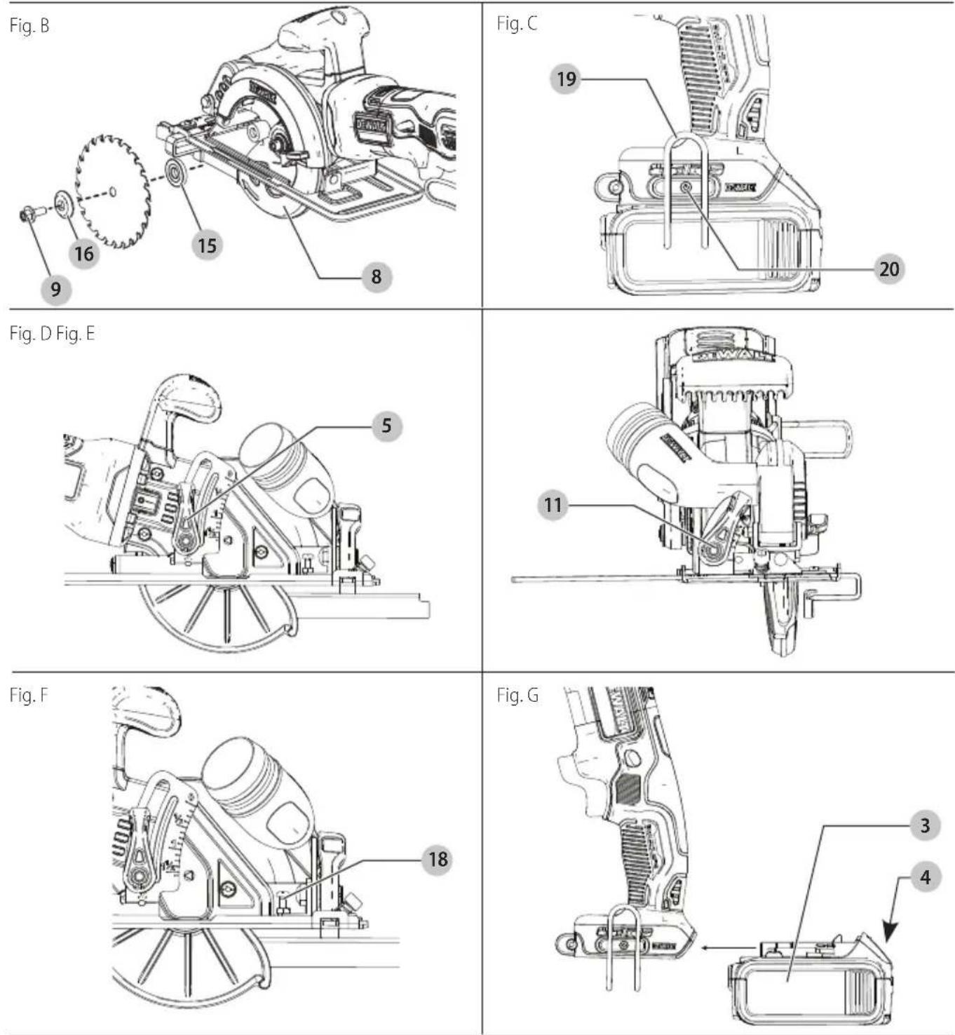
Fig. H
natural_image
Line drawing of a hand using a power tool to adjust or install a mechanical component (no text or symbols present)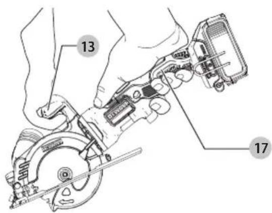
Fig. I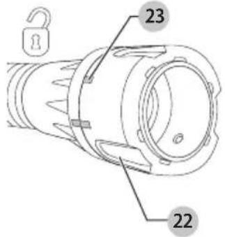 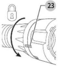 | Fig. J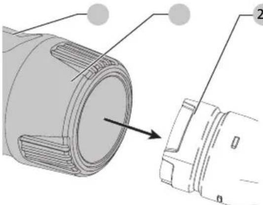 | 1252 |
Fig. K Fig. L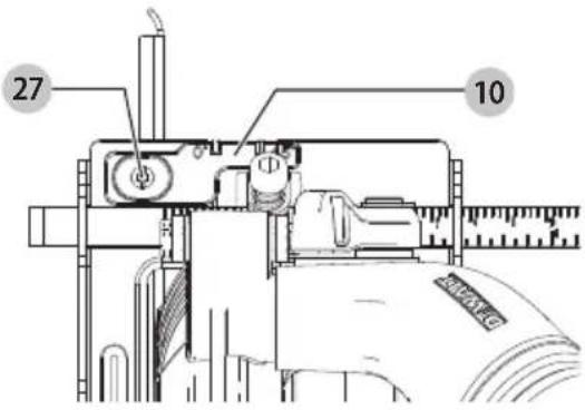 | 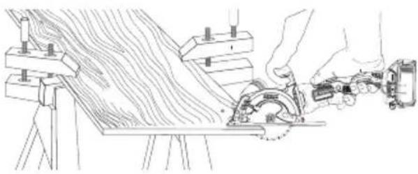 | |
Fig. M DO support board or panel NEAR the cut.SUPPORTER les panneaux PRÈS de la zone de coupe.SOPORTE la tabla o tablero CERCA del corte.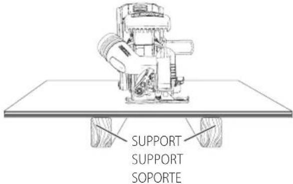 | Fig. N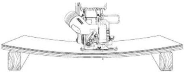 DON'T support board or panel AWAY from the cut.NE PAS PLACER le support du panneauLOIN de la zone de coupe.NO SOPORTE la tabla o tablero LEJOS del corte. DON'T support board or panel AWAY from the cut.NE PAS PLACER le support du panneauLOIN de la zone de coupe.NO SOPORTE la tabla o tablero LEJOS del corte. | |
Fig. O Fig. P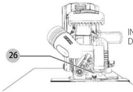 | INSTALL RIP FENCEIN THIS DIRECTIONPOSER LE GUIDELONGITUDINALDANS CE SENSISTALE LA CERCACE CORTE EN ESTADIRECCIÓN← | 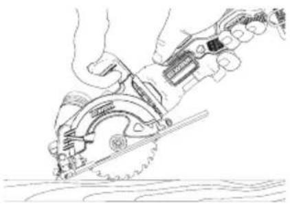 |
Intended Use
This circular saw is designed for professional wood cutting and fiber cement applications. DO nOT cut metal, plastic, concrete, masonry. DO nOT use for wet tile application. Maximum cutting depth is 1-11/20" (39.5 mm).
DO nOT use under wet conditions or in presence of flammable liquids or gases.
This circular saw is a professional power tool.
DO nOT let children come into contact with the tool. Supervision is required when inexperienced operators use this tool.
GENERAL POWER TOOL SAFETY WARNINGS
WARNING: Read all safety warnings, instructions, illustrations and specifications provided with this power tool. Failure to follow all instructions listed below may result in electric shock, fire and/or serious injury.
SAVE ALL WARNINGS AND INSTRUCTIONS FOR FUTURE REFERENCE.
The term "power tool" in the warnings refers to your mains-operated (corded) power tool or battery-operated (cordless) power tool.
1) Work Area Safety
a) Keep work area clean and well lit. Cluttered or dark areas invite accidents.
b) Do not operate power tools in explosive atmospheres, such as in the presence of flammable liquids, gases or dust. Power tools create sparks which may ignite the dust or fumes.
c) Keep children and bystanders away while operating a power tool. Distractions can cause you to lose control.
2) Electrical Safety
a) Power tool plugs must match the outlet. Never modify the plug in any way. Do not use any adapter plugs with earthed (grounded) power tools. Unmodified plugs and matching outlets will reduce risk of electric shock.
b) Avoid body contact with earthed or grounded surfaces, such as pipes, radiators, ranges and refrigerators. There is an increased risk of electric shock if your body is earthed or grounded.
c) Do not expose power tools to rain or wet conditions. Water entering a power tool will increase the risk of electric shock.
d) Do not abuse the cord. Never use the cord for carrying, pulling or unplugging the power tool. Keep cord away from heat, oil, sharp edges or moving parts. Damaged or entangled cords increase the risk of electric shock.
e) When operating a power tool outdoors, use an extension cord suitable for outdoor use. Use of a cord suitable for outdoor use reduces the risk of electric shock.
f) If operating a power tool in a damp location is unavoidable, use a ground fault circuit interrupter (GFCI) protected supply. Use of a GFCI reduces the risk of electric shock.
3) Personal Safety
a) Stay alert, watch what you are doing and use common sense when operating a power tool. Do not use a power tool while you are tired or under the influence of drugs, alcohol or medication. A moment of
inattention while operating power tools may result in serious personal injury.
b) Use personal protective equipment. Always wear eye protection. Protective equipment such as dust mask, non-skid safety shoes, hard hat, or hearing protection used for appropriate conditions will reduce personal injuries.
c) Prevent unintentional starting. Ensure the switch is in the off-position before connecting to power source and/or battery pack, picking up or carrying the tool. Carrying power tools with your finger on the switch or energizing power tools that have the switch on invites accidents.
d) Remove any adjusting key or wrench before turning the power tool on. A wrench or a key left attached to a rotating part of the power tool may result in personal injury.
e) Do not overreach. Keep proper footing and balance at all times. This enables better control of the power tool in unexpected situations.
f) Dress properly. Do not wear loose clothing or jewelry. Keep your hair, clothing and gloves away from moving parts. Loose clothes, jewelry or long hair can be caught in moving parts.
g) If devices are provided for the connection of dust extraction and collection facilities, ensure these are connected and properly used. Use of dust collection can reduce dust-related hazards.
h) Do not let familiarity gained from frequent use of tools allow you to become complacent and ignore tool safety principles. A careless action can cause severe injury within a fraction of a second.
4) Power Tool Use and Care
a) Do not force the power tool. Use the correct power tool for your application. The correct power tool will do the job better and safer at the rate for which it was designed.
b) Do not use the power tool if the switch does not turn it on and off. Any power tool that cannot be controlled with the switch is dangerous and must be repaired.
c) Disconnect the plug from the power source and/or remove the battery pack, if detachable, from the power tool before making any adjustments, changing accessories, or storing power tools. Such preventive safety measures reduce the risk of starting the power tool accidentally.
d) Store idle power tools out of the reach of children and do not allow persons unfamiliar with the power tool or these instructions to operate the power tool. Power tools are dangerous in the hands of untrained users.
e) Maintain power tools and accessories. Check for misalignment or binding of moving parts, breakage of parts and any other condition that may affect the power tool's operation. If damaged, have the power tool repaired before use. Many accidents are caused by poorly maintained power tools.
f) Keep cutting tools sharp and clean. Properly maintained cutting tools with sharp cutting edges are less likely to bind and are easier to control.
g) Use the power tool, accessories and tool bits etc. in accordance with these instructions, taking into account the working conditions and the work to be performed.
English
Use of the power tool for operations different from those intended could result in a hazardous situation.
h) Keep handles and grasping surfaces dry, clean and free from oil and grease. Slippery handles and grasping surfaces do not allow for safe handling and control of the tool in unexpected situations.
5) Battery Tool Use and Care
a) Recharge only with the charger specified by the manufacturer. A charger that is suitable for one type of battery pack may create a risk of fire when used with another battery pack.
b) Use power tools only with specifically designated battery packs. Use of any other battery packs may create a risk of injury and fire.
c) When battery pack is not in use, keep it away from other metal objects, like paper clips, coins, keys, nails, screws or other small metal objects, that can make a connection from one terminal to another. Shorting the battery terminals together may cause burns or a fire.
d) Under abusive conditions, liquid may be ejected from the battery; avoid contact. If contact accidentally occurs, flush with water. If liquid contacts eyes, additionally seek medical help. Liquid ejected from the battery may cause irritation or burns.
e) Do not use a battery pack or tool that is damaged or modified. Damaged or modified batteries may exhibit unpredictable behavior resulting in fire, explosion or risk of injury.
f) Do not expose a battery pack or tool to fire or excessive temperature. Exposure to fire or temperature above 265 °F (130 °C) may cause explosion.
g) Follow all charging instructions and do not charge the battery pack or tool outside the temperature range specified in the instructions. Charging improperly or at temperatures outside the specified range may damage the battery and increase the risk of fire.
6) Service
a) Have your power tool serviced by a qualified repair person using only identical replacement parts. This will ensure that the safety of the power tool is maintained.
b) Never service damaged battery packs. Service of battery packs should only be performed by the manufacturer or authorized service providers.
Safety Instructions for All Saws
Cutting Procedures
a) DANGER: Keep hands away from cutting area and the blade. Keep your second hand on auxiliary handle, or motor housing. If both hands are holding the saw, they cannot be cut by the blade.
b) Do not reach underneath the workpiece. The guard cannot protect you from the blade below the workpiece.
c) Adjust the cutting depth to the thickness of the workpiece. Less than a full tooth of the blade teeth should be visible below the workpiece.
d) Never hold the workpiece in your hands or across your leg while cutting. Secure the workpiece to a stable platform. It is important to support the work properly to minimize body exposure, blade binding, or loss of control.
e) Hold the power tool by insulated gripping surfaces, when performing an operation where the cutting tool
may contact hidden wiring. Contact with a "live" wire will also make exposed metal parts of the power tool "live" and could give the operator an electric shock
f) When ripping, always use a rip fence or straight edge guide. This improves the accuracy of cut and reduces the chance of blade binding.
g) Always use blades with correct size and shape (diamond versus round) of arbor holes. Blades that do not match the mounting hardware of the saw will run off-center, causing loss of control.
h) Never use damaged or incorrect blade washers or bolt. The blade washers and bolt were specially designed for your saw, for optimum performance and safety of operation.
Further Safety Instructions for all Saws
Kickback Causes and Related Warnings
- Kickback is a sudden reaction to a pinched, jammed or misaligned saw blade, causing an uncontrolled saw to lift up and out of the workpiece toward the operator;
- When the blade is pinched or jammed tightly by the kerf closing down, the blade stalls and the motor reaction drives the unit rapidly back toward the operator;
- If the blade becomes twisted or misaligned in the cut, the teeth at the back edge of the blade can dig into the top surface of the wood causing the blade to climb out of the kerf and jump back toward the operator.
Kickback is the result of saw misuse and/or incorrect operating procedures or conditions and can be avoided by taking proper precautions as given below:
a) Maintain a firm grip with both hands on the saw and position your arms to resist kickback forces. Position your body to either side of the blade, but not in line with the blade. Kickback could cause the saw to jump backwards, but kickback forces can be controlled by the operator, if proper precautions are taken.
b) When blade is binding, or when interrupting a cut for any reason, release the trigger and hold the saw motionless in the material until the blade comes to a complete stop. Never attempt to remove the saw from the work or pull the saw backward while the blade is in motion or kickback may occur. Investigate and take corrective actions to eliminate the cause of blade binding.
c) When restarting a saw in the workpiece, center the saw blade in the kerf so that the saw teeth are not engaged into the material. If a saw blade binds, it may walk up or kickback from the workpiece as the saw is restarted.
d) Support large panels to minimize the risk of blade pinching and kickback. Large panels tend to sag under their own weight. Supports must be placed under the panel on both sides, near the line of cut and near the edge of the panel.
e) Do not use dull or damaged blades. Unsharpened or improperly set blades produce narrow kerf causing excessive friction, blade binding and kickback.
f) Blade depth and bevel adjusting locking levers must be tight and secure before making cut. If blade adjustment shifts while cutting, it may cause binding and kickback.
g) Use extra caution when sawing into existing walls or other blind areas. The protruding blade may cut objects that can cause kickback.
Lower Guard Function
a) Check the lower guard for proper closing before each use. Do not operate the saw if the lower guard does not move freely and close instantly. Never clamp or tie the
lower guard into the open position. If saw is accidentally dropped, lower guard may be bent. Raise the lower guard with the retracting handle and make sure it moves freely and does not touch the blade or any other part, in all angles and depths of cut.
b) Check the operation of the lower guard spring. If the guard and the spring are not operating properly, they must be serviced before use. Lower guard may operate sluggishly due to damaged parts, gummy deposits, or a build-up of debris.
c) The lower guard may be retracted manually only for special cuts such as "plunge cuts" and "compound cuts." Raise the lower guard by retracting the handle and as soon as the blade enters the material, the lower guard must be released. For all other sawing, the lower guard should operate automatically.
d) Always observe that the lower guard is covering the blade before placing saw down on bench or floor.
An unprotected, coasting blade will cause the saw to walk backwards, cutting whatever is in its path. Be aware of the time it takes for the blade to stop after switch is released.
Additional Safety Information
WARNING: Never modify the power tool or any part of it. Damage or personal injury could result.
WARNING: ALWAYS use safety glasses. Everyday eyeglasses are NOT safety glasses. Also use face or dust mask if cutting operation is dusty. ALWAYS WEAR CERTIFIED SAFETY EQUIPMENT:
• ANSI Z87.1 eye protection (CAN/CSA Z94.3),
• ANSI S12.6 (S3.19) hearing protection,
• NIOSH/OSHA/MSHA respiratory protection.
WARNING: Some dust created by power sanding, sawing, grinding, drilling, and other construction activities contains chemicals known to the State of California to cause cancer, birth defects or other reproductive harm. Some examples of these chemicals are:
- lead from lead-based paints,
• crystalline silica from bricks and cement and other masonry products, and
• arsenic and chromium from chemically-treated lumber. Your risk from these exposures varies, depending on how often you do this type of work. To reduce your exposure to these chemicals: work in a well ventilated area, and work with approved safety equipment, such as those dust masks that are specially designed to filter out microscopic particles.
- Avoid prolonged contact with dust from power sanding, sawing, grinding, drilling, and other construction activities. Wear protective clothing and wash exposed areas with soap and water. Allowing dust to get into your mouth, eyes, or lay on the skin may promote absorption of harmful chemicals.
WARNING: Use of this tool can generate and/or disperse dust, which may cause serious and permanent respiratory or other injury. Always use NIOSH/OSHA approved respiratory protection appropriate for the dust exposure. Direct particles away from face and body.
WARNING: Always wear proper personal hearing protection that conforms to ANSI S12.6 (S3.19) during use. Under some conditions and duration of use, noise from this product may contribute to hearing loss.
AUTION: When not in use, place tool on its side on a stable surface where it will not cause a tripping
or falling hazard. Some tools with large battery packs will stand upright on the battery pack but may be easily knocked over.
- Air vents often cover moving parts and should be avoided. Loose clothes, jewelry or long hair can be caught in moving parts.
The label on your tool may include the following symbols. The symbols and their definitions are as follows:
V....volts Hz herlz or AC/DC....alternatingor direct current
min......minutes or DC......direct current Class I Construction ClassII Construction (double insulated)
class Construction (grounded) n_0 .....no load speed /min per minute n .....rated speed
BPM beats per minute earthing terminal
IPM impacts per minute safety alert symbol
RPM......revolutionsper minute ......visible radiation ......wearrespiratory
sfpm .... surface feet per minute SPM .... stroke per minute protection weareye protection
A.....amperes W.....watts ......wearhearing protection
W....water \~ or AC.....alternating current ....readall documentation
SAVE THESE INSTRUCTIONS FOR FUTURE USE
ASSEMBLY AND ADJUSTMENTS
WARNING: To reduce the risk of serious personal injury, turn unit off and remove the battery pack before making any adjustments or removing/installing attachments or accessories. An accidental start-up can cause injury.
Changing Blades (Fig. A, B)
To Install the Blade
WARNING: Remove battery before service, adjustment, installing or removing accessories.
- Place inner clamp washer 15 on saw spindle.
-
Retract the lower blade guard 8 and place blade on saw spindle against the inner clamp washer, making sure that the blade will rotate in the proper direction (the direction of the rotation arrow on the saw blade and the teeth must point in the same direction as the direction of rotation arrow on the lower blade guard). Do not assume that the printing on the blade will always be facing you when properly installed. When retracting the lower blade guard to install the blade, check the condition and operation of the lower blade guard to assure that it is working properly. Make sure it moves freely and does not touch the blade or any other part, in all angles and depths of cut.
-
Place outer clamp washer 16 on saw spindle with the large flat surface against the blade with beveled side facing out.
-
Thread blade clamping screw 9 into saw spindle by hand (screw has left-hand threads and must be turned counterclockwise to tighten).
-
Depress the blade lock button 12 while turning the saw spindle with the blade wrench 14 counterclockwise until the blade lock engages and the blade stops rotating.
English
- Tighten the blade clamping screw firmly with the blade wrench.
NOTE: Never engage the blade lock while saw is running, or engage in an effort to stop the tool. Never turn the saw on while the blade lock is engaged. Serious damage to your saw will result.
To Replace the Blade
WARNING: Remove battery before service, adjustment, installing or removing accessories.
- To loosen the blade clamping screw 9, depress the blade lock button 12 and turn the saw spindle with the blade wrench 14 until the blade lock engages and the blade stops rotating. With the blade lock engaged, turn the blade clamping screw clockwise with the blade wrench (screw has left-hand threads and must be turned clockwise to loosen).
- Remove the blade clamping screw 9 and outer clamp washer 16 only. Remove old blade.
- Clean any sawdust that may have accumulated in the guard or clamp washer area and check the condition and operation of the lower blade guard as previously outlined. Do not lubricate this area.
- Select the proper blade for the application (see Blades). Always use blades that are the correct size (diameter) with the proper size and shape center hole for mounting on the saw spindle. Always assure that the maximum recommended speed (rpm) on the saw blade meets or exceeds the speed (rpm) of the saw.
- Follow steps 2 through 6 under To Install the Blade, making sure that the blade will rotate in the proper direction.
Blades
AUTION: Burn hazard. Do not touch the blade immediately after use. Contact with the blade may result in personal injury.
WARNING: To minimize the risk of eye injury, always use eye protection. Carbide is a hard but brittle material. Foreign objects in the workpiece such as wire or nails can cause tips to crack or break. Only operate saw when proper saw blade guard is in place. Mount blade securely in proper rotation before using, and always use a clean, sharp blade.
WARNING: Do not cut ferrous or non-ferrous metals, steel, glass, masonry-type planking, or tile with this saw. Do not use abrasive wheels or blades. A dull blade will cause slow inefficient cutting, overload on the saw motor, excessive splintering, and could increase the possibility of kickback. Please refer to the table below to determine the correct size replacement blade for your model saw.
Blade Diameter Teeth Application
DWA412TCT 4-1/2" (115 mm) 24 Wood cutting
If you need assistance regarding blades, please call 1-800-4-DEWALT (1-800-433-9258).
Installing the Belt Hook (Fig. C)
WARNING: To reduce the risk of serious personal injury, turn unit off and remove the battery pack before making any adjustments or removing/installing attachments or accessories. An accidental start-up can cause injury.
WARNING: To reduce the risk of serious personal injury, ONLY use the tool's belt hook to hang the tool from a work belt. DO NOT use the belt hook for tethering or securing the tool to a person or object during use. DO NOT suspend tool overhead or suspend objects from the belt hook.
WARNING: To reduce the risk of serious personal injury, ensure the screw holding the belt hook is secure. iIMPORTAnT: When attaching or replacing the belt hook 19, use only the screw 20 that is provided. Be sure to securely tighten the screw.
If the hook is not desired at all, it can be removed from the tool.
Installing the Auxiliary Handle (Fig. A)
Using the supplied blade wrench 14 screw the auxiliary handle 13 into place as shown in Figure A. The saw can be used with or without the auxiliary handle in place.
Cutting Depth Adjustment (Fig. D)
- Hold the saw firmly and loosen (counterclockwise) the depth adjustment knob 5 and move shoe to obtain the desired depth of cut.
- Make sure the depth adjustment knob has been retightened (clockwise) before operating saw.
For the most efficient cutting action, set the depth adjustment so that one-half tooth of the blade will project below the material to be cut. This distance is from the tip of the tooth to the bottom of the gullet in front of it. This keeps blade friction at a minimum, removes sawdust from the cut, results in cooler, faster sawing and reduces the chance of kickback. A method for checking for correct cutting depth is shown in Figure D. Lay a piece of the material you plan to cut along the side of the blade, as shown, and observe how much tooth projects beyond the material.
Bevel Angle Adjustment (Fig. E)
The full range of the bevel adjustment is from 0^ to 45^ . The quadrant is graduated in increments of 15^ . On the front of the saw is a bevel angle adjustment mechanism consisting of a calibrated quadrant and a bevel adjustment knob 11.
To Set the Saw for a Bevel Cut
- Loosen (counterclockwise) the bevel adjustment knob 11 and tilt shoe to the desired angle by aligning the pointer with the desired angle mark.
- Retighten knob firmly (clockwise).
Shoe Adjustment for 90° Cuts (Fig. E, F) If Additional Adjustment is Needed
- Adjust the saw to 0^ bevel.
- Retract the lower blade guard. Place the saw on blade side.
- Loosen bevel adjustment knob 11. Place a square against the blade and shoe to adjust the 90° setting.
- Turn the calibration screw 18 so that the shoe will stop at the proper angle.
- Confirm the accuracy of the setting by checking the squareness of an actual cut on a scrap piece of material.
OPERATION
WARNING: To reduce the risk of serious personal injury, turn unit off and remove the battery pack before making any adjustments or removing/installing attachments or accessories. An accidental start-up can cause injury.
Installing and Removing the Battery Pack (Fig. G)
NOTE: For best results, make sure your battery pack is fully charged.
To install the battery pack 3 into the tool handle, align the battery pack with the rails inside the tool's handle and slide it into the handle until the battery pack is firmly seated in the tool and ensure that it does not disengage.
To remove the battery pack from the tool, press the release button 4 and firmly pull the battery pack out of the tool handle. Insert it into the charger.
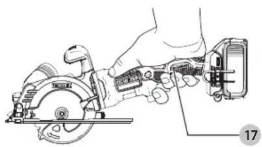
Proper Hand Position (Fig. H)
WARNING: To reduce the risk of serious personal injury, ALWAYS use proper hand position as shown.
WARNING: To reduce the risk of serious personal injury, ALWAYS hold securely in anticipation of a sudden reaction. Proper hand position requires one hand on the main handle 17 or, if the auxiliary handle is attached, one hand on the main handle 17 and one hand on the auxiliary handle 13.
Trigger Switch (Fig. A)
WARNING: This tool has no provision to lock the trigger switch in the ON position and should never be locked ON by any other means.
Release the trigger switch lock-off button 1 by pressing the lock-off button. Pull the trigger switch 2 to turn the motor on. At this time you can let go of the lock-off button. Releasing the trigger switch turns the motor off.
Dust Extraction (Fig. I, J)
Your saw has a built-in dust port 21 which allows either the supplied dust bag 24 or a shop vacuum system to be connected. The built-in dust port utilizes the DEWALT AirLock® connection making it compatible with the DEWALT dust extractors.
To Attach a Dust Extractor (Fig. I)
Your DEWALT circular saw is fitted with the DEWALT AirLock® connection system. The AirLock® allows for a fast, secure connection between the dust extractor and power tool. The AirLock® connector 22 connects directly to DEWALT compatible tools.
- Ensure the collar on the AirLock ^® connector is in the unlock position. (Refer to Figure I.) Align notches 23 on collar and AirLock ^® connector as shown for unlock and lock positions.
- Push the AirLock ^® connector onto the adapter connector point.
- Rotate the collar to the locked position.
NOTE: The ball bearings inside collar lock into slot and secure the connection. The power tool is now securely connected to the dust extractor.
To Attach the Dust Bag (Fig. J)
- While holding the saw, fit the dust bag collar 25 to the dust port 21 as shown in Figure J.
- Turn the collar 25 clockwise to lock the dust bag 24 in place.
To Empty the Dust Bag (Fig. J)
- While holding the saw, turn the collar 25
counterclockwise to unlock the dust bag 24. -
Remove dust bag from the saw and gently shake or tap the dust bag to empty.
-
Reattach the dust bag back onto the dust port and lock into place by turning the dust bag collar clockwise.
You may notice that all the dust will not come free from the bag. This will not affect sanding performance but will reduce the saw's dust collection efficiency. To restore your saw's dust collection efficiency, depress the spring inside the dust bag when you are emptying it and tap it on the side of the trash can or dust receptacle.
Lower Blade Guard
WARNING: The lower blade guard is a safety feature which reduces the risk of serious personal injury. Never use the saw if the lower blade guard is missing, damaged, misassembled or not working properly. Do not rely on the lower blade guard to protect you under all circumstances. Your safety depends on following all warnings and precautions as well as proper operation of the saw. Prior to use, the check lower guard operation by manually opening the guard using the lower guard blade retracting lever then releasing it from the fully open position. If the guard does not operate smoothly, close quickly or completely then do not use the saw and contact your DEWALT service center for repairs. If the lower blade guard is missing or not working properly, have the saw serviced before using. To assure product safety and reliability, repair, maintenance and adjustment should be performed by an authorized service center or other qualified service organization, always using identical replacement parts.
Kerf Indicator (Fig. A, K)
The front of the saw shoe has a kerf indicator 10 for vertical and bevel cutting. This indicator enables you to guide the saw along cutting lines penciled on the material being cut. The kerf indicator lines up with the left (outer) side of the saw blade, which makes the slot or "kerf" cut by the moving blade fall to the right of the indicator. Guide along the penciled cutting line so that the kerf falls into the waste or surplus material. To adjust the kerf indicator 10, loosen the kerf indicator screw 27 with the blade wrench 14 and move the indicator left or right as needed. Tighten screw when finished adjusting the indicator.
Workpiece Support (Fig. H, L–N)
WARNING: It is important to support the work properly and to hold the saw firmly to prevent loss of control which could cause personal injury. Figure H illustrates proper hand support of the saw. Maintain a firm grip with both hands on the saw and position your body and arm to allow you to resist kickback if it occurs. ALWAYS TURN OFF TOOL AND REMOVE BATTERY BEFORE MAKING ANY ADJUSTMENTS! Figure L shows proper sawing position. Note that hands are kept away from cutting area. To avoid kickback, DO support board or panel NEAR the cut (Fig. M). DON'T support board or panel away from the cut (Fig. N).
Place the work with its "good" side – the one on which appearance is most important – down. The saw cuts upward, so any splintering will be on the work face that is up when you cut it.
Cutting (Fig. L)
Place the wider portion of the saw shoe on that part of the workpiece which is solidly supported, not on the section that will fall off when the cut is made. As an example,
ENGLISH
Figure L illustrates the RIGHT way to cut off the end of a board. Always clamp work. Don't try to hold short pieces by hand! Remember to support cantilevered and overhanging material. Use caution when sawing material from below.
Be sure saw is up to full speed before blade contacts material to be cut. Starting saw with blade against material to be cut or pushed forward into kerf can result in kickback. Push the saw forward at a speed which allows the blade to cut without laboring.
Hardness and toughness can vary even in the same piece of material, and knotty or damp sections can put a heavy load on the saw. When this happens, push the saw more slowly, but hard enough to keep working without much decrease in speed. Forcing the saw can cause rough cuts, inaccuracy, kickback, and over-heating of the motor.
Should your cut begin to go off the line, don't try to force it back on. Release the trigger switch and allow blade to come to a complete stop. Then you can withdraw the saw, sight anew, and start a new cut slightly inside the wrong one. Withdraw the saw if you must shift the cut. Forcing a correction inside the cut can stall the saw and lead to kickback.
IF SAW STALLS, RELEASE THE TRIGGER SWITCH AND BACK THE SAW UNTIL IT IS LOOSE. BE SURE BLADE IS STRAIGHT IN THE CUT AND CLEAR OF THE CUTTING EDGE BEFORE RESTARTING.
As you finish a cut, release the trigger switch and allow the blade to stop before lifting the saw from the work. As you lift the saw, the spring-tensioned lower blade guard will automatically close under the blade. Remember the blade is exposed until this occurs. Never reach under the work for any reason. When you have to retract the lower blade guard manually (as is necessary for starting pocket cuts), always use the retracting lever.
WARNING: When cutting thin strips, be careful to ensure that small cutoff pieces don't hang up on the inside of the lower blade guard.
Ripping (Fig. A, O)
Ripping is the process of cutting wider boards into narrower strips – cutting grain lengthwise. Hand guiding is more difficult for this type of sawing and the use of a DEWALT rip fence is recommended.
Installing the Rip Fence
You can install a rip fence on your circular saw by loosening the rip fence locking screw 26 with the included blade wrench 14 and inserting the rip fence as shown in Figure O. When the rip fence is at the desired position, use the blade wrench to tighten the rip fence locking screw, locking it in place.
Pocket Cutting (Fig. P)
WARNING: Never tie the lower blade guard in a raised position. Never move the saw backwards when pocket cutting. This may cause the saw to raise up off the work surface, which could cause injury.
A pocket cut is one that is made in a floor, wall or other flat surface.
- Adjust the saw shoe so the blade cuts at desired depth.
- Tilt the saw forward and rest front of the shoe on material to be cut.
-
Using the lower blade guard retracting lever, retract the lower blade guard to an upward position. Lower the rear of the shoe until the blade teeth almost touch the cutting line.
-
Release the lower blade guard (its contact with the work will keep it in position to open freely as you start the cut). Remove your hand from the lower blade guard retracting lever and firmly grip the auxiliary handle, as shown in Figure P. Position your body and arm to allow you to resist kickback if it occurs.
- Make sure blade is not in contact with cutting surface before starting saw.
- Start the motor and gradually lower the saw until its shoe rests flat on the material to be cut. Advance saw along the cutting line until cut is completed.
- Release the trigger switch and allow the blade to stop completely before withdrawing the blade from the material.
- When starting each new cut, repeat the above steps.
MAINTENANCE
WARNING: To reduce the risk of serious personal injury, turn unit off and remove the battery pack before making any adjustments or removing/installing attachments or accessories. An accidental start-up can cause injury.
Your DEWALT power tool has been designed to operate over a long period of time with a minimum of maintenance. Continuous satisfactory operation depends upon proper tool care and regular cleaning.
Cleaning
WARNING: Blow dirt and dust out of the guarding system and all air vents with clean, dry air at least once a week. To minimize the risk of eye injury, always wear ANSI Z87.1 approved eye protection when performing this procedure.
WARNING: Never use solvents or other harsh chemicals for cleaning the non-metallic parts of the tool. These chemicals may weaken the plastic materials used in these parts. Use a cloth dampened only with water and mild soap. Never let any liquid get inside the tool; never immerse any part of the tool into a liquid.
Accessories
WARNING: Since accessories, other than those offered by DEWALT, have not been tested with this product, use of such accessories with this product could be hazardous. To reduce the risk of injury, only DEWALT recommended accessories should be used with this product.
Recommended accessories for use with your product are available at extra cost from your local dealer or authorized service center. If you need assistance in locating any accessory, please contact DEWALT. Call 1-800-4-DEWALT (1-800-433-9258) or visit our website: www.dewalt.com.
Repairs
The charger and batteries are not serviceable. There are no serviceable parts inside the charger or battery pack.
WARNING: To assure product SAFETY and RELIABILITY, repairs, maintenance and adjustment (including brush inspection and replacement, when applicable) should be performed by a factory service center or an authorized service center. Always use identical replacement parts.
Register Online
Thank you for your purchase. Register your product now for:
- WARRANTY SERVICE: Registering your product will help you obtain more efficient warranty service in case there is a problem with your product.
- CONFIRMATION OF OWNERSHIP: In case of an insurance loss, such as fire, flood or theft, your registration of ownership will serve as your proof of purchase.
• FOR YOUR SAFETY: Registering your product will allow us to contact you in the unlikely event a safety notification is required under the Federal Consumer Safety Act.
Register online at www.dewalt.com/account-login.
Three-Year Limited Warranty
For warranty terms, go to www.dewalt.com/support/warranty.
To request a written copy of the warranty terms, contact: Customer Service at DEWALT Industrial Tool Co., 701 East Joppa Road, Towson, MD 21286 or call 1-800-4-DEWALT (1-800-433-9258).
LATIN AMERICA: This warranty does not apply to products sold in Latin America. For products sold in Latin America, see country-specific warranty information contained in the packaging, call the local company or see website for warranty information.
FREE WARNING LABEL REPLACEMENT: If your warning labels become illegible or are missing, call 1-800-4-DEWALT (1-800-433-9258) for a free replacement.
FRAnÇAis
Usage Prévu
fabrication classe II (double isolation)
Eje Central Lázaro Cárdenas No. 18 - Local (55) 5588 9377 D, Col. Obrera
MERIDA, YUC
Calle 63 #459-A - Col. Centro (999) 928 5038
MONTERREY, N.L.
Av. Francisco I. Madero 831 Poniente - Col. (818) 375 23 13 Centro
PUEBLA, PUE
17 Norte #205 - Col. Centro (222) 246 3714
QUERETARO, QRO
Av. San Roque 274 - Col. San Gregorio (442) 2 17 63 14
SAN LUIS POTOSI, SLP
Col. Santa Fe Alvaro Obregon,
Ciudad de Mexico, Mexico.
C.P 01210
TEL(52) 55 53267100
R.F.C.BDE8106261W7
Registro en Línea
WARNING: Use of any other battery packs may create a risk of injury and fire.
NOTE: DO NOT charge when the battery pack is below 40 °F ( 4.5 °C ) or above 104 °F ( 40 °C ). Do not store or use the tool and battery pack in locations where the temperature may reach or exceed 104 °F ( 40 °C ).

- Definitions: Safety Alert Symbols and Words
- Intended Use
- GENERAL POWER TOOL SAFETY WARNINGS
- SAVE ALL WARNINGS AND INSTRUCTIONS FOR FUTURE REFERENCE.
- 1) Work Area Safety
- 2) Electrical Safety
- 3) Personal Safety
- 4) Power Tool Use and Care
- English
- 5) Battery Tool Use and Care
- 6) Service
- Safety Instructions for All Saws
- Cutting Procedures
- Further Safety Instructions for all Saws
- Kickback Causes and Related Warnings
- Lower Guard Function
- Additional Safety Information
- SAVE THESE INSTRUCTIONS FOR FUTURE USE
- ASSEMBLY AND ADJUSTMENTS
- Changing Blades (Fig. A, B)
- To Install the Blade
- To Replace the Blade
- Blades
- Installing the Belt Hook (Fig. C)
- Installing the Auxiliary Handle (Fig. A)
- Cutting Depth Adjustment (Fig. D)
- Bevel Angle Adjustment (Fig. E)
- To Set the Saw for a Bevel Cut
- Shoe Adjustment for 90° Cuts (Fig. E, F) If Additional Adjustment is Needed
- OPERATION
- Installing and Removing the Battery Pack (Fig. G)
- Proper Hand Position (Fig. H)
- Trigger Switch (Fig. A)
- Dust Extraction (Fig. I, J)
- To Attach a Dust Extractor (Fig. I)
- To Attach the Dust Bag (Fig. J)
- To Empty the Dust Bag (Fig. J)
- Lower Blade Guard
- Kerf Indicator (Fig. A, K)
- Workpiece Support (Fig. H, L–N)
- Cutting (Fig. L)
- Ripping (Fig. A, O)
- Installing the Rip Fence
- Pocket Cutting (Fig. P)
- MAINTENANCE
- Cleaning
- Accessories
- Repairs
- Register Online
- Three-Year Limited Warranty
- FRAnÇAis
- Usage Prévu
- MERIDA, YUC
- MONTERREY, N.L.
- PUEBLA, PUE
- QUERETARO, QRO
- SAN LUIS POTOSI, SLP
- Registro en Línea
Brand : DEWALT
Model : DCS571P1
Category : Saw