
DWE576 - Saw DEWALT - Free user manual and instructions
Find the device manual for free DWE576 DEWALT in PDF.


| Brand | DeWalt |
| Model | DWE576 |
| Product type | Circular saw |
| Voltage | 230 V |
| Power consumption | 1600 W |
| No-load speed | 5200 min⁻¹ |
| Blade diameter | 190 mm |
| Max. cutting depth | 61 mm |
| Bore | 30 mm |
| Bevel adjustment | 0° to 57° (stops at 22.5° and 45°) |
| Weight | 4.0 kg |
| Sound pressure level (L_PA) | 88 dB(A) |
| Sound power level (L_WA) | 99 dB(A) |
| Vibration (wood cutting) | < 2.5 m/s² |
| Insulation | Double insulation (class II) |
| Blade guard | Spring-loaded lower guard |
| Auxiliary handle | Yes |
| Parallel guide | Included |
| Dust extraction nozzle | Included |
| Compatible guide rail | Optional |
| Intended use | Professional wood cutting |
| Warranty | 1 year (see conditions) |
| Cleaning | Compressed air or soft brush; do not use solvents |
| Lubrication | Sealed bearings; annual gear case greasing at service center |
| Repairability | Repair only by a DeWalt authorized service center |
Frequently Asked Questions - DWE576 DEWALT
User questions about DWE576 DEWALT
0 question about this device. Answer the ones you know or ask your own.
Ask a new question about this device
Download the instructions for your Saw in PDF format for free! Find your manual DWE576 - DEWALT and take your electronic device back in hand. On this page are published all the documents necessary for the use of your device. DWE576 by DEWALT.
USER MANUAL DWE576 DEWALT
English (original instructions)
Figure 9
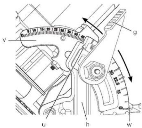
Figure 10

natural_image
Technical line drawing of a mechanical component with a ruler and flange (no text or symbols)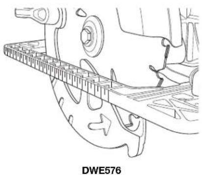
natural_image
Technical line drawing of a mechanical component with no visible text or symbolsFigure 11
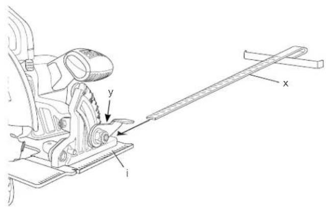
Figure 12

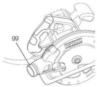
Figure 13

Figure 14

Figure 15

DWE576

Figure 16

natural_image
Technical line drawings of a mechanical device and a circular saw (no text or symbols)Figure 17

natural_image
Technical line drawing of a mechanical assembly with no visible text or symbolsFigure 18

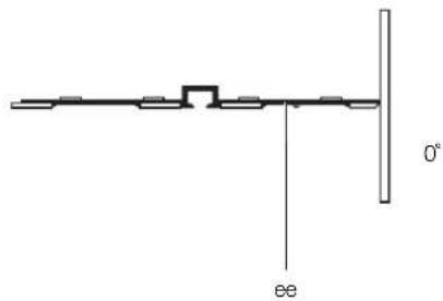
Figure 19
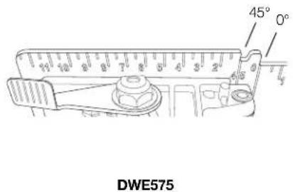
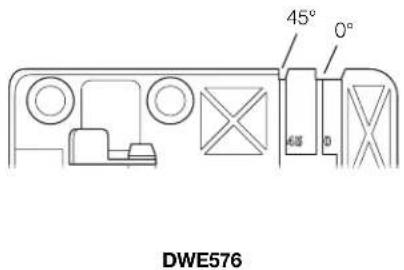
Figure 20

natural_image
Technical line drawing of a mechanical device with no visible text or symbolsFigure 21

natural_image
Technical line drawing of a mechanical assembly or mounting bracket (no text or symbols)Figure 22

Figure 23

natural_image
Line drawing of a sewing machine on a wooden table (no text or symbols)Figure 24

natural_image
Diagram showing a circular prohibition symbol crossed over a wooden table with two chairs, no text or symbols present.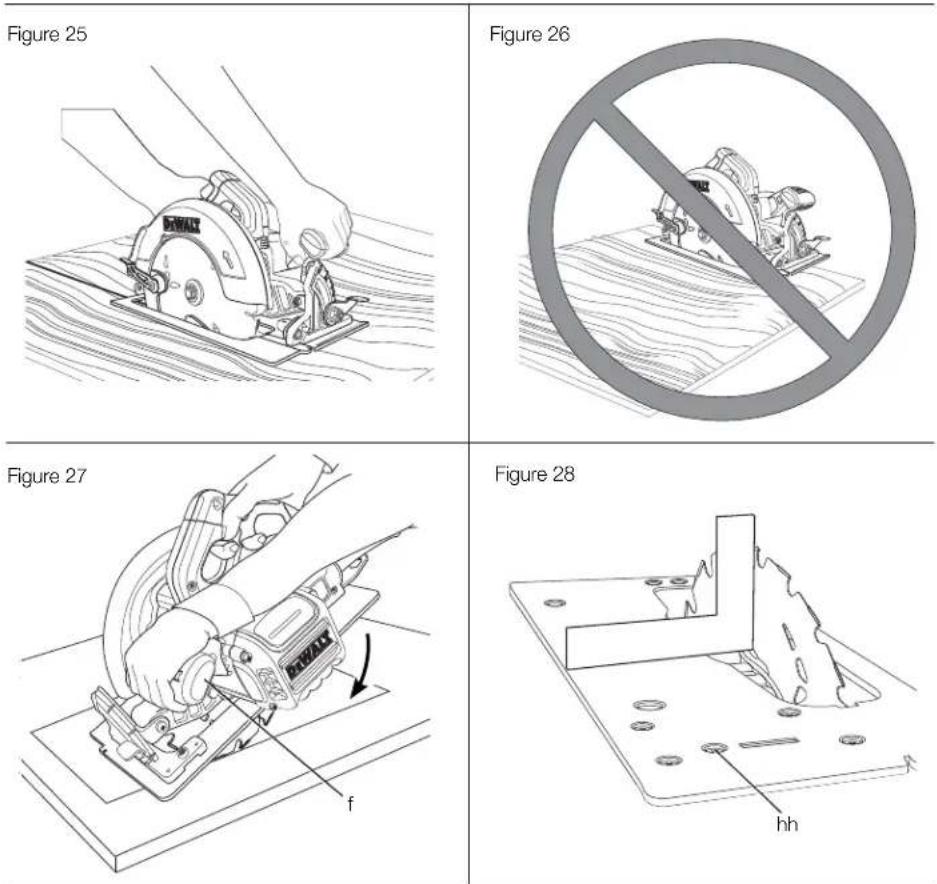
Figure 29
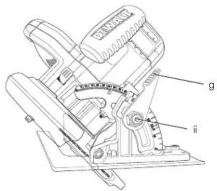
Figure 30

natural_image
Illustration of a hand holding a flexible hose with a lock icon and directional arrow (no text or symbols)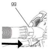

natural_image
Illustration of a hand holding a flexible hose with a padlock, no text or symbols present190 mm RUNDSAV DWE575, DWE576
Tillykke!
SÅDAN UDSKIFTES KLINGEN (FIG. 2–5)
PLACERING AF RUNDSAVEN PÅ STYRESKINNEN (FIG. 1, 14)
SPLITTERSCHUTZ ANPASSEN (ABB. 14)
You have chosen a DEWALT tool. Years of experience, thorough product development and innovation make DEWALT one of the most reliable partners for professional power tool users.
Technical Data
| DWE575 | DWE576 | ||
| Voltage V 230 230U.K. & Ireland V 115 | 115 | ||
| Type | 1 | 1 | |
| Power input | W | 1600 | 1600 |
| No-load speed | min^1 | 5200 | 5200 |
| Blade diameter | mm | 190 190 | |
| Maximum depth of cut | mm | 67 | 61 |
| Blade bore | mm | 30 | 30 |
| Bevel angle adjustment | 57^ | 57^ | |
| Weight | kg 4.0 | 4.0 | |
| L_in (sound pressure) | dB(A) | 88 | 88 |
| K_in (sound pressure uncertainty) | dB(A) | 3 | 3 |
| L_out (sound power) | dB(A) | 99 | 99 |
| K_out (sound power uncertainty) | dB(A) | 3 | 3 |
Vibration total values (triax vector sum) determined according to EN 60745:
| Vibration emission value a _h,w = | cutting wood | ||
| m/s2 | < 2.5 | < 2.5 | |
| Uncertainty K = | m/s2 | 1.5 | 1.5 |
The vibration emission level given in this information sheet has been measured in accordance with a standardised test given in EN 60745 and may be used to compare one tool with another. It may be used for a preliminary assessment of exposure.

WARNING: The declared vibration emission level represents the main applications of the tool. However if the tool is used for different applications, with different accessories or poorly maintained, the vibration emission may differ. This may significantly increase the exposure level over the total working period.
An estimation of the level of exposure to vibration should also take into account the times when the tool is switched off
or when it is running but not actually doing the job. This may significantly reduce the exposure level over the total working period.
Identify additional safety measures to protect the operator from the effects of vibration such as: maintain the tool and the accessories, keep the hands warm, organisation of work patterns.
Fuses
| Europe | 230 V tools | 10 Amperes, mains |
| U.K. & Ireland | 230 V tools | 13 Amperes, in plugs |
Definitions: Safety Guidelines
The definitions below describe the level of severity for each signal word. Please read the manual and pay attention to these symbols.

DANGER: Indicates an imminently hazardous situation which, if not avoided, will result in death or serious injury.

WARNING: Indicates a potentially hazardous situation which, if not avoided, could result in death or serious injury.

CAUTION: Indicates a potentially hazardous situation which, if not avoided, may result in minor or moderate injury.
NOTICE: Indicates a practice not related to personal injury which, if not avoided, may result in property damage.

Denotes risk of electric shock.

Denotes risk of fire.
EC-Declaration of Conformity
MACHINERY DIRECTIVE

DWE575, DWE576
DEWALT declares that these products described under Technical Data are in compliance with: 2006/42/EC, EN 60745-1, EN 60745-2-5.
ENGLISH
These products also comply with Directive 2004/108/EC and 2011/65/EC. For more information, please contact DEWALT at the following address or refer to the back of the manual.
The undersigned is responsible for compilation of the technical file and makes this declaration on behalf of DeWALT.

Horst Grossmann
Vice President Engineering and
Product Development
DEWALT, Richard-Klinger-Strasse 11,
D-65510, Idstein, Germany
07.05.2012

WARNING: To reduce the risk of injury, read the instruction manual.
General Power Tool Safety Warnings

WARNING! Read all safety warnings and all instructions. Failure to follow the warnings and instructions may result in electric shock, fire and/or serious injury.
SAVE ALL WARNINGS AND INSTRUCTIONS FOR FUTURE REFERENCE
The term "power tool" in the warnings refers to your mains-operated (corded) power tool or battery-operated (cordless) power tool.
1) WORK AREA SAFETY
a) Keep work area clean and well lit.
Cluttered or dark areas invite accidents.
b) Do not operate power tools in explosive atmospheres, such as in the presence of flammable liquids, gases or dust. Power tools create sparks which may ignite the dust or fumes.
c) Keep children and bystanders away while operating a power tool. Distractions can cause you to lose control.
2) ELECTRICAL SAFETY
a) Power tool plugs must match the outlet. Never modify the plug in any way. Do not use any adapter plugs with earthed (grounded) power tools. Unmodified plugs and matching outlets will reduce risk of electric shock.
b) Avoid body contact with earthed or grounded surfaces such as pipes, radiators, ranges and refrigerators. There
is an increased risk of electric shock if your body is earthed or grounded.
c) Do not expose power tools to rain or wet conditions. Water entering a power tool will increase the risk of electric shock.
d) Do not abuse the cord. Never use the cord for carrying, pulling or unplugging the power tool. Keep cord away from heat, oil, sharp edges or moving parts. Damaged or entangled cords increase the risk of electric shock.
e) When operating a power tool outdoors, use an extension cord suitable for outdoor use. Use of a cord suitable for outdoor use reduces the risk of electric shock.
f) If operating a power tool in a damp location is unavoidable, use a residual current device (RCD) protected supply. Use of an RCD reduces the risk of electric shock.
3) PERSONAL SAFETY
a) Stay alert, watch what you are doing and use common sense when operating a power tool. Do not use a power tool while you are tired or under the influence of drugs, alcohol or medication. A moment of inattention while operating power tools may result in serious personal injury.
b) Use personal protective equipment. Always wear eye protection. Protective equipment such as dust mask, non-skid safety shoes, hard hat, or hearing protection used for appropriate conditions will reduce personal injuries.
c) Prevent unintentional starting. Ensure the switch is in the off position before connecting to power source and/or battery pack, picking up or carrying the tool. Carrying power tools with your finger on the switch or energising power tools that have the switch on invites accidents.
d) Remove any adjusting key or wrench before turning the power tool on. A wrench or a key left attached to a rotating part of the power tool may result in personal injury.
e) Do not overreach. Keep proper footing and balance at all times. This enables better control of the power tool in unexpected situations.
f) Dress properly. Do not wear loose clothing or jewellery. Keep your hair, clothing and gloves away from moving parts. Loose clothes, jewellery or long hair can be caught in moving parts.
g) If devices are provided for the connection of dust extraction and collection facilities,
ENGLISH
ensure these are connected and properly used. Use of dust collection can reduce dust-related hazards.
4) POWER TOOL USE AND CARE
a) Do not force the power tool. Use the correct power tool for your application. The correct power tool will do the job better and safer at the rate for which it was designed.
b) Do not use the power tool if the switch does not turn it on and off. Any power tool that cannot be controlled with the switch is dangerous and must be repaired.
c) Disconnect the plug from the power source and/or the battery pack from the power tool before making any adjustments, changing accessories, or storing power tools. Such preventive safety measures reduce the risk of starting the power tool accidentally.
d) Store idle power tools out of the reach of children and do not allow persons unfamiliar with the power tool or these instructions to operate the power tool. Power tools are dangerous in the hands of untrained users.
e) Maintain power tools. Check for misalignment or binding of moving parts, breakage of parts and any other condition that may affect the power tool's operation. If damaged, have the power tool repaired before use. Many accidents are caused by poorly maintained power tools.
f) Keep cutting tools sharp and clean. Properly maintained cutting tools with sharp cutting edges are less likely to bind and are easier to control.
g) Use the power tool, accessories and tool bits etc., in accordance with these instructions taking into account the working conditions and the work to be performed. Use of the power tool for operations different from those intended could result in a hazardous situation.
5) SERVICE
a) Have your power tool serviced by a qualified repair person using only identical replacement parts. This will ensure that the safety of the power tool is maintained.
ADDITIONAL SPECIFIC SAFETY RULES FOR CIRCULAR SAWS
Safety Instructions for All Saws
a) △ DANGER: Keep hands away from cutting area and the blade. Keep your second hand
on auxiliary handle, or motor housing. If both hands are holding the saw, they cannot be cut by the blade.
b) Do not reach underneath the workpiece. The guard cannot protect you from the blade below the workpiece.
c) Adjust the cutting depth to the thickness of the workpiece. Less than a full tooth of the blade teeth should be visible below the workpiece.
d) Never hold piece being cut in your hands or across your leg. Secure the workpiece to a stable platform. It is important to support the work properly to minimize body exposure, blade binding, or loss of control.
e) Hold power tool by insulated gripping surfaces when performing an operation where the cutting tool may contact hidden wiring. Contact with a "live" wire will also make exposed metal parts of the power tool "live" and shock the operator.
f) When ripping, always use a rip fence or straight edge guide. This improves the accuracy of cut and reduces the chance of blade binding.
g) Always use blades with correct size and shape (diamond versus round) of arbour holes. Blades that do not match the mounting hardware of the saw will run eccentrically, causing loss of control.
h) Never use damaged or incorrect blade washers or bolt. The blade washers and bolt were specially designed for your saw, for optimum performance and safety of operation.
Causes and Operator Prevention of Kickback
- Kickback is a sudden reaction to a pinched, bound or misaligned saw blade, causing an uncontrolled saw to lift up and out of the workpiece toward the operator;
- When the blade is pinched or bound tightly by the kerf closing down, the blade stalls and the motor reaction drives the unit rapidly back toward the operator;
- If the blade becomes twisted or misaligned in the cut, the teeth at the back edge of the blade can dig into the top surface of the wood causing the blade to climb out of the kerf and jump back toward the operator.
Kickback is the result of saw misuse and/or incorrect operating procedures or conditions and can be avoided by taking proper precautions as given below:
ENGLISH
a) Maintain a firm grip with both hands on the saw and position your arms to resist kickback forces. Position your body to either side of the blade, but not in line with the blade. Kickback could cause the saw to jump backwards, but kickback forces can be controlled by the operator, if proper precautions are taken.
b) When blade is binding, or when interrupting a cut for any reason, release the trigger and hold the saw motionless in the material until the blade comes to a complete stop. Never attempt to remove the saw from the work or pull the saw backward while the blade is in motion or kickback may occur. Investigate and take corrective actions to eliminate the cause of blade binding.
c) When restarting a saw in the workpiece, centre the saw blade in the kerf and check that saw teeth are not engaged into the material. If saw blade is binding, it may walk up or kickback from the workpiece as the saw is restarted.
d) Support large panels to minimise the risk of blade pinching and kickback. Large panels tend to sag under their own weight. Supports must be placed under the panel on both sides, near the line of cut and near the edge of the panel.
e) Do not use dull or damaged blades.
Unsharpened or improperly set blades produce narrow kerf causing excessive friction, blade binding and kickback.
f) Blade depth and bevel adjusting locking levers must be tight and secure before making cut. If blade adjustment shifts while cutting, it may cause binding and kickback.
g) Use extra caution when sawing into existing walls or other blind areas. The protruding blade may cut objects that can cause kickback.
Lower Guard Safety Instructions
a) Check lower guard for proper closing before each use. Do not operate the saw if lower guard does not move freely and close instantly. Never clamp or tie the lower guard into the open position. If saw is accidentally dropped, lower guard may be bent. Raise the lower guard with the retracting handle and make sure it moves freely and does not touch the blade or any other part, in all angles and depths of cut.
b) Check the operation of the lower guard spring. If the guard and the spring are not operating properly, they must be serviced
before use. Lower guard may operate sluggishly due to damaged parts, gummy deposits, or a build-up of debris.
c) Lower guard should be retracted manually only for special cuts such as "plunge cuts" and "compound cuts". Raise lower guard by retracting handle and as soon as blade enters the material, the lower guard must be released. For all other sawing, the lower guard should operate automatically.
d) Always observe that the lower guard is covering the blade before placing saw down on bench or floor. An unprotected, coasting blade will cause the saw to walk backwards, cutting whatever is in its path. Be aware of the time it takes for the blade to stop after switch is released.
Additional Safety Instructions for Circular Saws
- Wear ear protectors. Exposure to noise can cause hearing loss.
- Wear a dust mask. Exposure to dust particles can cause breathing difficulty and possible injury.
- Do not use blades of larger or smaller diameter than recommended. For the proper blade rating refer to the technical data. Use only the blades specified in this manual, complying with EN 847-1.
- Never use abrasive cut-off wheels.
- Do not use water feed attachments.
- Use clamps or another practical way to secure and support the workpiece to a stable platform. Holding the work by hand or against your body leaves it unstable and may lead to loss of control.
- Keep your body positioned to either side of the blade, but not in line with the saw blade. KICKBACK could cause the saw to jump backwards (see Causes and Operator Prevention of Kickback and KICKBACK).
- Air vents often cover moving parts and should be avoided. Loose clothes, jewellery or long hair can be caught in moving parts.
Residual Risks
The following risks are inherent to the use of circular saws.
- Injuries caused by touching the rotating parts or hot part of the tool.
In spite of the application of the relevant safety regulations and the implementation of safety devices, certain residual risks cannot be avoided. These are:
- Impairment of hearing.
– Risk of squeezing fingers when changing the accessory.
– Health hazards caused by breathing dust developed when working in wood.
Markings on Tool
The following pictograms are shown on the tool:

Read instruction manual before use.

Wear ear protection.

Wear eye protection.
DATE CODE POSITION (FIG. 1)
The date code (jj), which also includes the year of manufacture, is printed into the housing.
Example:
2012 XX XX
Year of Manufacture
Package Contents
The package contains:
1 Circular saw
1 Circular saw blade
1 Blade wrench
1 Parallel fence
1 Dust extraction spout
1 Instruction manual
1 Exploded drawing
- Check for damage to the tool, parts or accessories which may have occurred during transport.
• Take the time to thoroughly read and understand this manual prior to operation.
Description (fi g. 1)
WARNING: Never modify the power tool or any part of it. Damage or personal injury could result.
a. Trigger switch
b. Trigger switch lock-off button
c. Main handle
d. Blade lock
e. End cap
f. Auxiliary handle
g. Bevel adjustment lever
h. Bevel angle adjustment mechanism
f. Auxiliary handle
g. Bevel adjustment lever
h. Bevel angle adjustment mechanism
i. Base plate
j. Lower blade guard
k. Blade clamping screw
I. Lower guard lever
m. Upper blade guard
INTENDED USE
These heavy-duty circular saws are designed for professional wood cutting applications. DO NOT use water feed attachments with this saw. DO NOT use abrasive wheels or blades. DO NOT use under wet conditions or in the presence of flammable liquids or gases.
These heavy-duty saws are professional power tools. DO NOT let children come into contact with the tool. Supervision is required when inexperienced operators use this tool.
- This product is not intended for use by persons (including children) suffering from diminished physical, sensory or mental abilities; lack of experience, knowledge or skills unless they are supervised by a person responsible for their safety. Children should never be left alone with this product.
Electrical Safety
The electric motor has been designed for one voltage only. Always check that the power supply corresponds to the voltage on the rating plate.

Your DEWALT tool is double insulated in accordance with EN 60745; therefore no earth wire is required.

IG: 115 V units have to be operated via a fail-safe isolating transformer with an earth screen between the primary and secondary winding.
If the supply cord is damaged, it must be replaced by a specially prepared cord available through the DEWALT service organisation.
Mains Plug Replacement (U.K. & Ireland Only)
If a new mains plug needs to be fitted:
- Safely dispose of the old plug.
ENGLISH
- Connect the brown lead to the live terminal in the plug.
- Connect the blue lead to the neutral terminal.

Follow the fitting instructions supplied with good quality plugs. Recommended fuse: 13 A.
Using an Extension Cable
If an extension cable is required, use an approved 3-core extension cable suitable for the power input of this tool (see Technical Data). The minimum conductor size is 1.5 mm ^2 ; the maximum length is 30 m.
When using a cable reel, always unwind the cable completely.
ASSEMBLY AND ADJUSTMENTS

Changing Blades
TO INSTALL THE BLADE (FIG. 2-5)
- Using the lower guard lever (l), retract the lower blade guard (j) and place blade on saw spindle against the inner clamp washer (n), making sure that the blade will rotate in the proper direction (the direction of the rotation arrow on the saw blade and the teeth must point in the same direction as the direction of rotation arrow on the saw). Do not assume that the printing on the blade will always be facing you when properly installed. When retracting the lower blade guard to install the blade, check the condition and operation of the lower blade guard to assure that it is working properly. Make sure it moves freely and does not touch the blade or any other part, in all angles and depths of cut.
- Place outer clamp washer (o) on saw spindle with the beveled edge facing out. Make sure the 30 mm diameter on the blade side of the clamp fits into the 30 mm hole in the saw blade to ensure centering of the blade.
-
Thread the blade clamping screw (k) onto the saw spindle by hand (screw has right-hand threads and must be turned clockwise to tighten).
-
Depress the blade lock (d) while turning the saw spindle with the blade wrench (p) stored underneath the main handle (c) (fig. 5), until the blade lock engages and the blade stops rotating.
-
Tighten the blade clamping screw firmly with the blade wrench.
NOTICE: Never engage the blade lock while saw is running, or engage in an effort to stop the tool. Never turn the saw on while the blade lock is engaged. Serious damage to your saw will result.
TO REPLACE THE BLADE (FIG. 2-5)
- To loosen the blade clamping screw (k), depress the blade lock (d) and turn the saw spindle with the blade wrench (p), stored underneath the main handle (c), until the blade lock engages and the blade stops rotating. With the blade lock engaged, turn the blade clamping screw counterclockwise with the blade wrench (screw has right-hand threads and must be turned counterclockwise to loosen).
- Remove the blade clamping screw (k) and outer clamp washer (o). Remove old blade.
- Clean any sawdust that may have accumulated in the guard or clamp washer area and check the condition and operation of the lower blade guard as previously outlined. Do not lubricate this area.
- Select the proper blade for the application (refer to Blades). Always use blades that are the correct size (diameter) with the proper size and shape center hole for mounting on the saw spindle. Always assure that the maximum recommended speed (rpm) on the saw blade meets or exceeds the speed (rpm) of the saw.
- Follow steps 1 through 5 under To Install the Blade, making sure that the blade will rotate in the proper direction.
LOWER BLADE GUARD

WARNING: The lower blade guard is a safety feature that reduces the risk of serious personal injury. Never use the saw if the lower guard is missing, damaged, misassembled or not working properly. Do not rely on the lower blade guard to protect you under all circumstances. Your safety depends on following all warnings and precautions as well as proper operation of the saw. Check the lower blade guard for proper closing before each use. If the lower blade guard is missing or not working properly, have the saw serviced
before using. To assure product safety and reliability, repair, maintenance and adjustment should be performed by an authorized service center or other qualified service organization, always using identical replacement parts.
CHECKING THE LOWER GUARD (FIG. 1)
- Turn tool off and disconnect from power supply.
- Rotate the lower guard lever (fig. 1, l) from the fully closed position to the fully open position.
- Release the lever and observe the guard (j) return to the fully closed position.
The tool should be serviced by a qualified service center if it:
• fails to return to the fully closed position,
- moves intermittently or slowly, or
- contacts the blade or any part of the tool in all angles and depth of cut.
BLADES

WARNING: To minimize the risk of eye injury, always use eye protection. Carbide is a hard but brittle material. Foreign objects in the workpiece such as wire or nails can cause tips to crack or break. Only operate saw when proper saw blade guard is in place. Mount blade securely in proper rotation before using, and always use a clean, sharp blade.
| Diameter | Teeth | Application |
| 190 mm | 18 Fast rip | ||
| 190 | mm | 24 | Rip |
190 mm 40 General purpose
If you need assistance regarding blades, please contact your local DEWALT dealer.
Kickback
Kickback is a sudden reaction to a pinched, bound or misaligned saw blade, causing an uncontrolled saw to lift up and out of the workpiece toward the operator. When the blade is pinched or bound tightly by the kerf closing down, the blade stalls and the motor reaction drives the unit rapidly back toward the operator. If the blade becomes twisted or misaligned in the cut, the teeth at the back edge of the blade can dig into the top surface of the material causing the blade to climb out of the kerf and jump back toward the operator.
Kickback is more likely to occur when any of the following conditions exists.
1. IMPROPER WORKPIECE SUPPORT
A. Sagging or improper lifting of the cut off piece can cause pinching of the blade and lead to kickback (fig. 24).
B. Cutting through material supported at the outer ends only can cause kickback. As the material weakens it sags, closing down the kerf and pinching the blade (fig. 24).
C. Cutting off a cantilevered or overhanging piece of material from the bottom up in a vertical direction can cause kickback. The falling cut off piece can pinch the blade.
D. Cutting off long narrow strips can cause kickback. The cut off strip can sag or twist closing the kerf and pinching the blade.
E. Snagging the lower guard on a surface below the material being cut momentarily reduces operator control. The saw can lift partially out of the cut increasing the chance of blade twist.
2. IMPROPER DEPTH OF CUT SETTING ON SAW
To make the most efficient cut, the blade should protrude only far enough to expose a tooth as shown in figure 8. This allows the shoe to support the blade and minimizes twisting and pinching in the material. See the section titled Depth of Cut Adjustment.
3. BLADE TWISTING (MISALIGNMENT IN CUT)
A. Pushing harder to cut can cause the blade to twist.
B. Trying to turn the saw in the cut (trying to get back on the marked line) can cause blade twist.
C. Overreaching or operating the saw with poor body control (out of balance), can result in twisting the blade.
D. Changing hand grip or body position while cutting can result in blade twist.
E. Backing up the saw to clear blade can lead to twist.
4. USE OF DULL OR DIRTY BLADES
Dull blades cause increased loading of the saw. To compensate, an operator will usually push harder which further loads the unit and promotes twisting of the blade in the kerf. Worn blades may also have insufficient body
ENGLISH
clearance which increases the chance of binding and increased loading.
5. RESTARTING A CUT WITH THE BLADE TEETH JAMMED AGAINST THE MATERIAL
The saw should be brought up to full operating speed before starting a cut or restarting a cut after the unit has been stopped with the blade in the kerf. Failure to do so can cause stalling and kickback.
Any other conditions which could result in pinching, binding, twisting, or misalignment of the blade could cause kickback. Refer to the sections Additional Specific Safety Rules for Circular Saws and Blades for procedures and techniques that will minimize the occurrence of kickback.
Depth of Cut Adjustment (fi g. 6–8)
- Raise the depth adjustment lever (q) to loosen.
- To obtain the correct depth of cut, align the appropriate mark on the depth adjustment strap (s) with notch (r) on the upper blade guard.
- Tighten the depth adjustment lever.
- For the most efficient cutting action using a carbide tipped saw blade, set the depth adjustment so that about one half of a tooth projects below the surface of the wood to be cut.
- A method of checking for the correct cutting depth is shown in figure 8. Lay a piece of the material you plan to cut along the side of the blade, as shown in the figure, and observe how much tooth projects beyond the material.
ADJUSTING DEPTH ADJUSTMENT LEVER (FIG. 7)
It may be desirable to adjust the depth adjustment lever (q). It may loosen in time and hit the base plate before tighten ing.
To Tighten the Lever:
- Hold depth adjustment lever (q) and loosen the locknut (t).
- Adjust the depth adjustment lever by rotating it in the desired direction about 1/8 of a revolution.
- Retighten nut.
Bevel Angle Adjustment (fi g. 9)
The bevel angle adjustment mechanism (h) can be adjusted between 0^ and 57^ .
To achieve better accuracy in cutting, use the fine adjustment markings located on the pivot bracket (v).
-
Raise the bevel adjustment lever (g) to loosen.
-
Tilt the base plate to the desired angle by aligning the fine bevel pointer (u) with the desired angle mark on the pivot bracket (v).
- Lower the bevel adjustment lever to retighten.
Bevel Detent (fi g. 9)
The DWE575 and DWE576 are equipped with a bevel defent feature. As you tilt the base plate you will hear a click and feel the base plate stop at both 22.5 and 45 degrees. If either of these is the desired angle, retighten the lever (g) by lowering it. If you desire another angle, continue tilting the base plate until the coarse bevel pointer (w) or the fine pointer (u) aligns with the desired mark.
Cut Length Indicator (fi g. 10)
The markings on the side of the base plate show the length of the slot being cut into the material at the full depth of the cut. The markings are in increments of 5 mm (1/5").
Mounting and Adjusting the Parallel Fence (fi g. 11)
The parallel fence (x) is used for cutting parallel to the edge of the workpiece.
MOUNTING
- Slacken the parallel fence adjustment knob (y) to allow the parallel fence to pass.
- Insert the parallel fence (x) in the base plate (i) as shown.
- Tighten the parallel fence adjustment knob (y).
ADJUSTING
- Slacken the fence adjustment knob (y) and set the parallel fence (x) to the desired width. The adjustment can be read on the parallel fence scale.
- Tighten the fence adjustment knob (y).
Mounting the Dust Extraction Spout (fi g. 1, 6, 12)
Your DWE575/DWE576 circular saw is supplied with a dust extraction spout.
TO INSTALL DUST EXTRACTION SPOUT
- Fully loosen depth adjustment lever (q).
- Place base plate (i) in the lowest position.
-
Align the left half of the dust extraction spout (gg) over upper blade guard (m) as shown. Be sure to insert the tab into the casting notch on the tool. When installed correctly, it will snap fully over the original depth of cut pointer.
-
Align the right-hand piece with the left.
- Insert screws and tighten securely.
Guide Rail System (DWE576, fi g. 13)
Guide rails, available in different lengths as accessories, allow the use of the circular saw for precise, straight clean cuts and simultaneously protect the workpiece surface against damage. In conjunction with additional accessories, exact angled cuts, mitre cuts and fitting work can be completed with the guide rail system.
Clamps (dd) are available to secure the guide rail (bb) to the workpiece (fig. 13). Use of these clamps (dd) ensure that the guide rail (bb) is securely attached to the workpiece (cc) for safe working. Once the guide rail is set to the cut line and securely fixed to the workpiece, there is no movement during cutting.
IMPORTANT : The height scale on the unit is set for using the saw without a guide rail. When using the saw on the guide rail the difference in height will be approximately 5.0 mm.
SETTING THE CIRCULAR SAW TO THE GUIDE RAIL (FIG. 1, 14)
The clearance between the circular saw and the guide rail (fig. 14, bb) must be very small to achieve best cutting results. The smaller this clearance the better the straight line finish will be on the workpiece.
The clearance can be set with the two rail adjusters (fig. 1, z, aa) for each channel in the base for 0^ cutting (z) and for 1 - 45^ bevel cutting (aa). The rail adjusters are precision cams that allow for the reduction of clearance between the unit and guide rail. Once these adjusters have been set, sideways movement of the saw during cutting is kept to a minimum while allowing a smooth cutting action.
NOTE: The adjusters are set to minimum clearance in the factory and may need adjusting and setting before the unit is used. Use the following instructions for setting the circular saw to the guide rail.
REMEMBER: Set the rail adjusters on the saw to the guide rail.
- Undo the screw inside the rail adjuster to allow for adjustment between the saw and the guide rail.
- Retract the lower guard and place the unit on the guide rail, ensuring the blade is in the highest position.
-
Rotate the adjuster until saw locks on guide rail.
IMPORTANT: Make sure the saw is securely attached to the rail by trying to push the saw forward. Ensure there is no movement of the saw. -
Rotate the adjuster back slightly until saw slides easily along the rail.
- Hold the rail adjuster in position and tighten the screw again.
NOTE: ALWAYS adjust the system for use with other rails.
The rail adjusters are now set up to minimise sideways deviation when cutting with the saw on the guide rail.
Before using the saw, the anti-splinter guard (ee) on the guide rail will need tuning in. Refer to Tuning the Anti-Splinter Guard.
TUNING THE ANTI-SPLINTER GUARD (FIG. 14)
The guide rail (bb) is equipped with an anti-splinter guard (ee) that has to be tuned to the saw before the first use.
The anti-splinter guard (ee) is situated on each edge of the guide rail (fig. 14). The purpose of this anti-splinter guard is to provide the user with a visible blade cut line while reducing the chipping that occurs along the workpiece cut edge during cutting.
IMPORTANT: ALWAYS read and follow the Setting the Circular Saw to the Guide Rail before cutting the splinter guard!
STEPS TO TUNE THE ANTI-SPLINTER GUARD (FIG. 15–18)
- Place the guide rail (bb) on a scrap piece of wood (ff) with a minimum length of 100 mm overhanging the workpiece. Use a clamp to ensure that the guide rail is securely attached to the workpiece. This will ensure accuracy.
- Set the unit to a 20 mm depth of cut.
- Place the front of the saw on the overhang end of the guide rail, making sure that the blade is positioned in front of the rail edge (fig. 16).
- Turn the saw on and slowly cut the splinter guard along the full length of the rail in one continuous operation. The edge of the splinter guard now corresponds exactly to the cutting edge of the blade (fig. 17).
To tune in the anti-splinter guard on the other side of the guide rail, remove the saw from the rail and rotate the rail 180°. Repeat steps 1 through 4.
NOTE: If desired, the splinter guard can be bevelled to 45^ , then repeat steps 1 through 4. This allows one side of the rail for cutting parallel cuts and the other side of the rail is tuned in for 45^ bevel cuts (fig. 18).
NOTE: If the anti-splinter guard is tuned in for parallel cutting on both sides, then when the unit is bevelled, the blade will not run true to the edge of the anti-splinter guard. This is because the pivot
ENGLISH
point of the unit bevel is not stationary and the blade moves out over when the unit is bevelled.
USING THE CORRECT CHANNEL (FIG. 19-21)
The saw base plate consists of two channels. One channel is for making parallel cuts and the other channel is for making bevel cuts.
The indicators at the front of the base plate (fig. 19) indicate which channel is for which application. When making cuts make sure that the line on the base plate is in line with the channel on the guide rail. Figure 20 shows the saw in the parallel cutting position relative to the guide rail. Figure 21 shows the saw in the bevel cutting position relative to the guide rail.
Prior to Operation
- Make sure the guards have been mounted correctly. The saw blade guard must be in closed position.
- Make sure the saw blade rotates in the direction of the arrow on the blade.
- Do not use excessively worn saw blades.
OPERATION
Instructions for Use
WARNING: Always observe the safety instructions and applicable regulations.
WARNING: To reduce the risk of injury, turn unit off and disconnect machine from power source before installing and removing accessories, before adjusting or changing set-ups or when making repairs. An accidental start-up can cause injury.
Proper Hand Position (fi g. 22)
WARNING: To reduce the risk of serious personal injury, ALWAYS use proper hand position as shown.
WARNING: To reduce the risk of serious personal injury, ALWAYS hold securely in anticipation of a sudden reaction.
Proper hand position requires one hand on the main handle (c), with the other hand on the auxiliary handle (f).
Switching On and Off (fi g. 1)
For safety reasons the trigger switch (a) of your tool is equipped with a lock-off button (b).
Press the lock-off button to unlock the tool.
To run the tool, press the trigger switch (a). As soon as the trigger switch is released, the lock-off switch is automatically activated to prevent unintended starting of the machine.
NOTICE: Do not switch the tool ON or OFF when the saw blade touches the workpiece or other materials.
Workpiece Support (fi g. 23–26)
WARNING: To reduce the risk of serious personal injury, support the work properly and hold the saw firmly to prevent loss of control.
Figures 23 and 25 show proper sawing position. Figures 24 and 26 show an unsafe condition. Hands should be kept away from cutting area, and power cord is positioned clear of the cutting area so that it will not get caught or hung up on the work.
To avoid kickback, ALWAYS support board or panel NEAR the cut, (fig. 23 and 25). DON'T support board or panel away from the cut (fig. 24 and 26). When operating the saw, keep the cord away from the cutting area and prevent it from becoming hung up on the work piece.
ALWAYS DISCONNECT SAW BEFORE MAKING ANY ADJUST MENTS! Place the work with its "good" side—the one on which appearance is most important—down. The saw cuts upward, so any splintering will be on the work face that is up when you saw it.
Cutting
WARNING: Never attempt to use this tool by resting it upside down on a work surface and bringing the material to the tool. Always securely clamp the workpiece and bring the tool to the workpiece, securely holding the tool with two hands as shown in figure 25.
Place the wider portion of the saw base plate on that part of the work piece which is solidly supported, not on the section that will fall off when the cut is made. As examples, figure 25 illustrates the RIGHT way to cut off the end of a board. Always clamp work. Don't try to hold short pieces by hand! Remember to support cantilevered and overhanging material. Use caution when sawing material from below.
Be sure saw is up to full speed before blade contacts material to be cut. Starting saw with blade against material to be cut or pushed forward into kerf can result in kickback. Push the saw forward at a speed which allows the blade to cut without laboring. Hardness and toughness can vary even in the same piece of material, and knotty or damp sections can
put a heavy load on the saw. When this happens, push the saw more slowly, but hard enough to keep working without much decrease in speed. Forcing the saw can cause rough cuts, inaccuracy, kickback, and over-heating of the motor. Should your cut begin to go off the line, don't try to force it back on. Release the switch and allow blade to come to a complete stop. Then you can withdraw the saw, sight anew, and start a new cut slightly inside the wrong one. In any event, withdraw the saw if you must shift the cut. Forcing a correction inside the cut can stall the saw and lead to kickback.
IF SAW STALLS, RELEASE THE TRIGGER AND BACK THE SAW UNTIL IT IS LOOSE. BE SURE BLADE IS STRAIGHT IN THE CUT AND CLEAR OF THE CUTTING EDGE BEFORE RESTARTING.
As you finish a cut, release the trigger and allow the blade to stop before lifting the saw from the work. As you lift the saw, the spring-tensioned telescoping guard will automatically close under the blade. Remember the blade is exposed until this occurs. Never reach under the work for any reason. When you have to retract the telescoping guard manually (as is necessary for starting pocket cuts) always use the retracting lever.
NOTE: When cutting thin strips, be careful to ensure that small cutoff pieces don't hang up on inside of lower guard.
POCKET CUTTING (FIG. 27)

WARNING: Never tie the blade guard in a raised position. Never move the saw backwards when pocket cutting. This may cause the unit to raise up off the work surface which could cause injury.
A pocket cut is one that is made in a floor, wall or other flat surface.
- Adjust the saw base plate so the blade cuts at desired depth.
- Tilt the saw forward and rest front of the base plate on material to be cut.
- Using the lower guard lever, retract lower blade guard to an upward position. Lower rear of base plate until blade teeth almost touch cutting line.
- Release the blade guard (its contact with the work will keep it in position to open freely as you start the cut). Remove hand from guard lever and firmly grip auxiliary handle (f), as shown in figure 27. Position your body and arm to allow you to resist kickback if it occurs.
-
Make sure blade is not in contact with cutting surface before starting saw.
-
Start the motor and gradually lower the saw until its base plate rests flat on the material to be cut. Advance saw along the cutting line until cut is completed.
- Release trigger and allow blade to stop completely before withdrawing the blade from the material.
- When starting each new cut, repeat as above.
Dust Extraction (fi g. 30)

WARNING: Risk of dust inhalation. To reduce the risk of personal injury, ALWAYS wear an approved dust mask.
A dust extraction spout (gg) is supplied with your tool.
Vacuum hoses of most common vacuum extractors will fit directly into the dust extraction spout.

WARNING: ALWAYS use a vacuum extractor designed in compliance with the applicable directives regarding dust emission when sawing wood. Vacuum hoses of most common vacuum cleaners will fit directly into the dust extraction outlet.
MAINTENANCE
Your DEWALT power tool has been designed to operate over a long period of time with a minimum of maintenance. Continuous satisfactory operation depends upon proper tool care and regular cleaning.

NG: To reduce the risk of injury, turn unit off and disconnect machine from power source before installing and removing accessories, before adjusting or changing set-ups or when making repairs. An accidental start-up can cause injury.

Lubrication
Self lubricating ball and roller bearings are used in the tool and relubrication is not required. However, it is recommended that, once a year, you take or send the tool to a service center for a thorough cleaning, inspection and lubrication of the gear case.
ENGLISH

Cleaning

WARNING: Blow dirt and dust out of the main housing with dry air as often as dirt is seen collecting in and around the air vents. Wear approved eye protection and approved dust mask when performing this procedure.

WARNING: Never use solvents or other harsh chemicals for cleaning the non-metallic parts of the tool. These chemicals may weaken the materials used in these parts. Use a cloth dampened only with water and mild soap. Never let any liquid get inside the tool; never immerse any part of the tool into a liquid.
LOWER GUARD
The lower guard should always rotate and close freely from a fully open to fully closed position. Always check for correct operation before cutting by fully opening the guard and letting it close. If the guard closes slowly or not completely, it will need cleaning or servicing. Do not use the saw until it functions correctly. To clean the guard, use dry air or a soft brush to remove all accumulated sawdust or debris from the path of the guard and from around the guard spring. Should this not correct the problem, it will need to be serviced by an authorized service center.
Base Plate Adjustment (fi g. 5, 28, 29)
Your base plate has been factory set to assure that the blade is perpendicular to the base plate. If after extended use you need to re-align the blade, follow the directions below:
ADJUSTING FOR 90 DEGREE CUTS
- Return the saw to 0 degrees bevel.
- Place the saw on its side, and retract the lower guard.
- Set the depth of cut to 51 mm (approximately 2").
- Loosen the bevel adjustment lever (Fig. 29, g). Place a square against the blade and the base plate as shown in figure 28.
- Using a wrench (p), turn the set screw (hh) on the underside of the base plate until the blade and the base plate are both in flush contact with the square. Retighten the bevel adjustment lever.
ADJUSTING BEVEL ADJUSTMENT LEVER (FIG. 29)
It may be desirable to adjust the bevel adjustment lever (g). It may loosen in time and hit the base plate before tighten ing.
To Tighten the Lever:
- Hold the bevel adjustment lever (g) and loosen the locknut (ii).
- Adjust the bevel adjustment lever by rotating it in the desired direction about 1/8 of a revolution.
- Retighten nut.
Blades
A dull blade will cause inefficient cutting, overload on the saw motor, excessive splintering and increase the possibility of kickback. Change blades when it is no longer easy to push the saw through the cut, when the motor is straining, or when excessive heat is built up in the blade. It is a good practice to keep extra blades on hand so that sharp blades are available for immediate use. Dull blades can be sharpened in most areas.
Hardened gum on the blade can be removed with kerosene, turpentine, or oven cleaner. Anti-stick coated blades can be used in applications where excessive build-up is encountered, such as pressure treated and green lumber.
Optional Accessories

WARNING: Since accessories, other than those offered by DEWALT, have not been tested with this product, use of such accessories with this tool could be hazardous. To reduce the risk of injury, only DEWALT recommended accessories should be used with this product.
DO NOT USE WATER FEED ATTACHMENTS WITH THIS SAW.
VISUALLY EXAMINE CARBIDE BLADES BEFORE USE. REPLACE IF DAMAGED.
Consult your dealer for further information on the appropriate accessories.
Protecting the Environment

Separate collection. This product must not be disposed of with normal household waste.
Should you find one day that your DEWALT product needs replacement, or if it is of no further use to you, do not dispose of it with household waste. Make this product available for separate collection.

Separate collection of used products and packaging allows materials to be recycled and used again. Re-use of recycled materials helps prevent environmental pollution and reduces the demand for raw materials.
Local regulations may provide for separate collection of electrical products from the household, at municipal waste sites or by the retailer when you purchase a new product.
DEWALT provides a facility for the collection and recycling of DEWALT products once they have reached the end of their working life. To take advantage of this service please return your product to any authorised repair agent who will collect them on our behalf.
You can check the location of your nearest authorised repair agent by contacting your local DEWALT office at the address indicated in this manual. Alternatively, a list of authorised DEWALT repair agents and full details of our after-sales service and contacts are available on the Internet at: www.2helpU.com.
GUARANTEE
DEWALT is confident of the quality of its products and offers an outstanding guarantee for professional users of the product. This guarantee statement is in addition to and in no way prejudices your contractual rights as a professional user or your statutory rights as a private non-professional user. The guarantee is valid within the territories of the Member States of the European Union and the European Free Trade Area.
• 30 DAY NO RISK SATISFACTION GUARANTEE •
If you are not completely satisfied with the performance of your DEWALT tool, simply return it within 30 days, complete with all original components, as purchased, to the point of purchase, for a full refund or exchange. The product must have been subject to fair wear and tear and proof of purchase must be produced.
• ONE YEAR FREE SERVICE CONTRACT •
If you need maintenance or service for your DEWALT tool, in the 12 months following purchase, you are entitled to one service free of charge. It will be undertaken free of charge at an authorised DEWALT repair agent. Proof of purchase must be produced. Includes labour. Excludes accessories and spare parts unless failed under warranty.
• ONE YEAR FULL WARRANTY •
If your DEWALT product becomes defective due to faulty materials or workmanship within 12 months from the date of purchase, DEWALT guarantees to replace all defective parts free of charge or – at our discretion – replace the unit free of charge provided that:
• The product has not been misused;
- The product has been subject to fair wear and tear;
• Repairs have not been attempted by unauthorised persons;
• Proof of purchase is produced;
- The product is returned complete with all original components.
If you wish to make a claim, contact your seller or check the location of your nearest authorised DEWALT repair agent in the DEWALT catalogue or contact your DEWALT office at the address indicated in this manual. A list of authorised DEWALT repair agents and full details of our after-sales service is available on the Internet at: www.2helpU.com.
ESPAÑOL
SIERRA CIRCULAR DE 190 mm DWE575, DWE576
¡Enhorabuena!
USO DEL CANAL ADECUADO (FIG. 19–21)
REEMPLACER LA LAME (FIG. 2-5)
VG: Never modify the power tool or any part of it. Damage or personal injury could result.
Vice President Engineering and Product Development
WAARSCHUWING! Lees alle

BEWAAR ALLE WAARSCHUWINGEN EN INSTRUCTIES ALS TOEKOMSTIG REFERENTIEMATERIAAL
POSITIE DATUMCODE (AFB. [FIG.] 1)
HET ZAAGBLAD INSTALLEREN (AFB. 2–5)
HET ZAAGBLAD VERVANGEN (AFB. 2–5)
WAARSCHUWING: Zet de
1) SIKKERHET PÅ ARBEIDSOMRÅDET
INSTALAR A LÂMINA (FIG. 2-5)
Vice President Engineering and Product
Development
DEWALT, Richard-Klinger-Strasse 11,
D-65510, Idstein, Germany
07.05.2012

DATUMKODPLACERING (FIG. 1)
ATT BYTA KLINGAN (FIG. 2-5)
190 mm DAÏRESEL TESTERE DWE575, DWE576
Tebrikler!

- mm RUNDSAV DWE575, DWE576
- Tillykke!
- SÅDAN UDSKIFTES KLINGEN (FIG. 2–5)
- PLACERING AF RUNDSAVEN PÅ STYRESKINNEN (FIG. 1, 14)
- SPLITTERSCHUTZ ANPASSEN (ABB. 14)
- Definitions: Safety Guidelines
- EC-Declaration of Conformity
- ENGLISH
- General Power Tool Safety Warnings
- SAVE ALL WARNINGS AND INSTRUCTIONS FOR FUTURE REFERENCE
- 1) WORK AREA SAFETY
- 2) ELECTRICAL SAFETY
- 3) PERSONAL SAFETY
- 4) POWER TOOL USE AND CARE
- 5) SERVICE
- ADDITIONAL SPECIFIC SAFETY RULES FOR CIRCULAR SAWS
- Safety Instructions for All Saws
- Causes and Operator Prevention of Kickback
- Lower Guard Safety Instructions
- Additional Safety Instructions for Circular Saws
- Residual Risks
- Markings on Tool
- DATE CODE POSITION (FIG. 1)
- Package Contents
- Description (fi g. 1)
- INTENDED USE
- Electrical Safety
- Mains Plug Replacement (U.K. & Ireland Only)
- Using an Extension Cable
- ASSEMBLY AND ADJUSTMENTS
- Changing Blades
- TO INSTALL THE BLADE (FIG. 2-5)
- TO REPLACE THE BLADE (FIG. 2-5)
- LOWER BLADE GUARD
- CHECKING THE LOWER GUARD (FIG. 1)
- BLADES
- Kickback
- IMPROPER WORKPIECE SUPPORT
- IMPROPER DEPTH OF CUT SETTING ON SAW
- BLADE TWISTING (MISALIGNMENT IN CUT)
- USE OF DULL OR DIRTY BLADES
- RESTARTING A CUT WITH THE BLADE TEETH JAMMED AGAINST THE MATERIAL
- Depth of Cut Adjustment (fi g. 6–8)
- ADJUSTING DEPTH ADJUSTMENT LEVER (FIG. 7)
- To Tighten the Lever:
- Bevel Angle Adjustment (fi g. 9)
- Bevel Detent (fi g. 9)
- Cut Length Indicator (fi g. 10)
- Mounting and Adjusting the Parallel Fence (fi g. 11)
- MOUNTING
- ADJUSTING
- Mounting the Dust Extraction Spout (fi g. 1, 6, 12)
- TO INSTALL DUST EXTRACTION SPOUT
- Guide Rail System (DWE576, fi g. 13)
- SETTING THE CIRCULAR SAW TO THE GUIDE RAIL (FIG. 1, 14)
- TUNING THE ANTI-SPLINTER GUARD (FIG. 14)
- STEPS TO TUNE THE ANTI-SPLINTER GUARD (FIG. 15–18)
- USING THE CORRECT CHANNEL (FIG. 19-21)
- Prior to Operation
- OPERATION
- Instructions for Use
- Proper Hand Position (fi g. 22)
- Switching On and Off (fi g. 1)
- Workpiece Support (fi g. 23–26)
- Cutting
- POCKET CUTTING (FIG. 27)
- Dust Extraction (fi g. 30)
- MAINTENANCE
- Lubrication
- Cleaning
- LOWER GUARD
- Base Plate Adjustment (fi g. 5, 28, 29)
- ADJUSTING FOR 90 DEGREE CUTS
- ADJUSTING BEVEL ADJUSTMENT LEVER (FIG. 29)
- Optional Accessories
- Protecting the Environment
- GUARANTEE
- • 30 DAY NO RISK SATISFACTION GUARANTEE •
- • ONE YEAR FREE SERVICE CONTRACT •
- • ONE YEAR FULL WARRANTY •
- ESPAÑOL
- SIERRA CIRCULAR DE 190 mm DWE575, DWE576
- ¡Enhorabuena!
- USO DEL CANAL ADECUADO (FIG. 19–21)
- REEMPLACER LA LAME (FIG. 2-5)
- BEWAAR ALLE WAARSCHUWINGEN EN INSTRUCTIES ALS TOEKOMSTIG REFERENTIEMATERIAAL
- POSITIE DATUMCODE (AFB. [FIG.] 1)
- HET ZAAGBLAD INSTALLEREN (AFB. 2–5)
- HET ZAAGBLAD VERVANGEN (AFB. 2–5)
- 1) SIKKERHET PÅ ARBEIDSOMRÅDET
- INSTALAR A LÂMINA (FIG. 2-5)
- DATUMKODPLACERING (FIG. 1)
- ATT BYTA KLINGAN (FIG. 2-5)
- mm DAÏRESEL TESTERE DWE575, DWE576
- Tebrikler!
Brand : DEWALT
Model : DWE576
Category : Saw