
DCS365N - Saw DEWALT - Free user manual and instructions
Find the device manual for free DCS365N DEWALT in PDF.

| Product type | Cordless sliding compound miter saw |
| Brand and model | DeWalt DCS365N |
| Nominal voltage | 18 V (Li-Ion) |
| Blade diameter | 184 mm |
| Blade bore | 16 mm |
| Blade body thickness | 1 mm |
| Maximum no-load speed | 3750 min⁻¹ |
| Crosscut capacity at 90° | 50 mm |
| Miter cut capacity at 45° | 35.3 mm |
| Miter range (max) | 48° left / 48° right |
| Bevel range (max) | 48° left / 0° right |
| Blade automatic stop time | < 10 seconds |
| Weight without battery | 10.5 kg |
| Sound pressure level (LPA) | 88 dB(A) |
| Sound power level (LWA) | 93 dB(A) |
| Vibration emission value | < 2.5 m/s² |
| Lighting system | XPS™ LED with projected blade shadow |
| Dust extraction | Integrated connection for bag or vacuum |
| Blade brake | Automatic electric |
| Package contents | Saw, blade wrench, 184 mm saw blade, side handle kit, dust bag, clamping piece, instruction manual (battery and charger according to model) |
| Maintenance and cleaning | Clean ventilation slots with compressed air; housing with damp cloth and mild soap; no lubrication needed |
| Safety | Blade brake, lower blade guard, trigger switch with lock-off lever, miter and bevel locks, locking pin in down position |
| Spare parts and repairability | 184 mm saw blades, 16 mm bore available; repairs by authorized DeWalt service center only |
Frequently Asked Questions - DCS365N DEWALT
User questions about DCS365N DEWALT
0 question about this device. Answer the ones you know or ask your own.
Ask a new question about this device
Download the instructions for your Saw in PDF format for free! Find your manual DCS365N - DEWALT and take your electronic device back in hand. On this page are published all the documents necessary for the use of your device. DCS365N by DEWALT.
USER MANUAL DCS365N DEWALT
English (original instructions) 36
OPGAVE DIAMETER T/EnDER
Generelle formal 184 mm 40
Fin traeskaring 184 mm 60
Miljobeskyttelese
You have chosen a DEWALT tool. Years of experience, thorough product development and innovation make DEWALT one of the most reliable partners for professional power tool users.
Technical Data
| DCS365 | ||
| Voltage V | DC | 18 |
| Type 1 | ||
| Battery type Li-Ion | ||
| Blade diameter mm 184 | ||
| Blade bore mm 16 | ||
| Blade body thickness mm 1 | ||
| Max. blade speed min | -1 | 3750 |
| Max. cross-cut capacity 90° | mm 50 | |
| Max. litre capacity 45° | mm | 35.3 |
| Mitre (max. positions) | left | 45° |
| right | 45° | |
| Bevel (max. positions) | left | 48° |
| right | 0° | |
| 0° litre | ||
| Resulting width at max. height 50 mm | mm | 250 |
| Resulting height at max. width 90 mm | mm | 15 |
| 45° litre left | ||
| Resulting width at max. height 50 mm | mm | 176 |
| Resulting height at max. width 90 mm | mm | 8 |
| 45° litre right | ||
| Resulting width at max. height 50 mm | mm | 176 |
| Resulting height at max. width 90 mm | mm | 8 |
| 45° bevel left | ||
| Resulting width at max. height 35 mm | mm 250 | |
| Automatic blade brake time | s | < 10 |
| Weight without battery | kg 10.5 | |
| Noise values and vibration values (triax vector sum) according to EN62841-3-9: | ||
| L_PA (emission sound pressure level) | dB(A) | 88 |
| LWA (sound power level) | dB(A) | 93 |
| K (uncertainty for the given sound level) | dB(A) | 2,0 |
| Vibration emission value ah= | m/s² | <2,5 |
| Uncertainty K= | m/s² 1,5 | |
The vibration emission level given in this information sheet has been measured in accordance with a standardised test given in EN62841-3-9 and may be used to compare one tool with another. It may be used for a preliminary assessment of exposure.
WARNING: The declared vibration emission level represents the main applications of the tool. However if the tool is used for different applications, with different accessories or poorly maintained, the vibration emission may differ. This may significantly increase the exposure level over the total working period.
An estimation of the level of exposure to vibration should also take into account the times when the tool is switched off or when it is running but not actually doing the job. This may significantly reduce the exposure level over the total working period.
Identify additional safety measures to protect the operator from the effects of vibration such as: maintain the tool and the accessories, keep the hands warm, organisation of work patterns.
EC-Declaration of Conformity
Machinery Directive

Cordless Sliding Compound Mitre Saw DCS365
D-WALT declares that these products described under Technical Data are in compliance with:
2006/42/EC,EN62841-1:2015,EN62841-3-9:2014.
These products also comply with Directive 2014/30/EU and 2011/65/EU. For more information, please contact DFWALT at the following address or refer to the back of the manual.
The undersigned is responsible for compilation of the technical file and makes this declaration on behalf of DFWALT.

Markus Rompel
Director Engineering
D-65510, Idstein, Germany
30.10.2015

WARNING: To reduce the risk of injury, read the instruction manual.
Definitions: Safety Guidelines
The definitions below describe the level of severity for each signal word. Please read the manual and pay attention to these symbols.

ER: Indicates an imminently hazardous situation which, if not d, will result in death or serious injury.

ING: Indicates a potentially hazardous situation which, if not d, could result in death or serious injury.

ON: Indicates a potentially hazardous situation which, if not d, may result in minor or moderate injury.
NOTICE: Indicates a practice not related to personal injury which, if not avoided, may result in property damage.

is risk of electric shock.

is risk of fire.
General Power Tool SafetyWarnings
WARNING: Read all safety warnings and all instructions. Failure to the warnings and instructions may result in electric shock, fire and/or serious injury.
SAVE ALL WARNING AND INSTRUCTIONS FOR FUTURE REFERENCE
The term "power tool" in the warnings refers to your mains-operated (corded) power tool or battery-operated (cordless) power tool.
1) Work area safety
a) Keep work area clean and well lit. Cluttered or dark areas invite accidents.
| Batteries Chargers/Charge | Times (Minutes) | ||||||||
| Cat # V | pc | Ah Weight (kg) DCB107 | DCB113 DCB115 DCB118 DCB132 DCB119 | ||||||
| DCB546 18/54 6.0/2.0 1.05 270 140 90 60 90 | X | ||||||||
| DCB547 18/54 9.0/3.0 1.25 420 220 140 85 | 140 X | ||||||||
| DCB181 | 18 | 1.5 | 0.35 | 70 | 35 | 22 | 22 | 22 | 45 |
| DCB182 | 18 | 4.0 | 0.61 | 185 | 100 | 60 | 60 | 60 | 120 |
| DCB183/8 | 18 | 2.0 | 0.40 | 90 | 50 | 30 | 30 | 30 | 60 |
| DCB184/8 | 18 | 5.0 | 0.62 | 240 | 120 | 75 | 75 | 75 | 150 |
| DCB185 | 18 | 1.3 | 0.35 | 60 | 30 | 22 | 22 | 22 | X |
| DCB187 | 18 | 3.0 | 0.48 | 140 | 70 | 45 | 45 | 45 | 90 |
b) Do not operate power tools in explosive atmospheres, such as in the presence of flammable liquids, gases or dust. Power tools create sparks which may ignite the dust or fumes.
c) Keep children and bystanders away while operating a power tool. Distractions can cause you to lose control.
2) Electrical safety
a) Power tool plugs must match the outlet. Never modify the plug in any way. Do not use any adapter plugs with earthed (grounded) power tools. Unmodified plugs and matching outlets will reduce risk of electric shock.
b) Avoid body contact with earthed or grounded surfaces such as pipes, radiators, ranges and refrigerators. There is an increased risk of electric shock if your body is earthed or grounded.
c) Do not expose power tools to rain or wet conditions. Water entering a power tool will increase the risk of electric shock.
d) Do not abuse the cord. Never use the cord for carrying, pulling or unplugging the power tool. Keep cord away from heat, oil, sharp edges or moving parts. Damaged or entangled cords increase the risk of electric shock.
e) When operating a power tool outdoors, use an extension cord suitable for outdoor use. Use of a cord suitable for outdoor use reduces the risk of electric shock.
f) If operating a power tool in a damp location is unavoidable, use a residual current device (RCD) protected supply. Use of an RCD reduces the risk of electric shock.
3) Personal safety
a) Stay alert, watch what you are doing and use common sense when operating a power tool. Do not use a power tool while you are tired or under the influence of drugs, alcohol or medication. A moment of inattention while operating power tools may result in serious personal injury.
b) Use personal protective equipment. Always wear eye protection. Protective equipment such as dust mask, non-skid safety shoes, hard hat, or hearing protection used for appropriate conditions will reduce personal injuries.
c) Prevent unintentional starting. Ensure the switch is in the off position before connecting to power source and/or battery pack, picking up or carrying the tool. Carrying power tools with your finger on the switch or energising power tools that have the switch on invites accidents.
d) Remove any adjusting key or wrench before turning the power tool on. A wrench or a key left attached to a rotating part of the power tool may result in personal injury.
e) Do not overreach. Keep proper footing and balance at all times. This enables better control of the power tool in unexpected situations.
f) Dress properly. Do not wear loose clothing or jewellery. Keep your hair, clothing and gloves away from moving parts. Loose clothes, jewellery or long hair can be caught in moving parts.
g) If devices are provided for the connection of dust extraction and collection facilities, ensure these are connected and properly used. Use of dust collection can reduce dust-related hazards.
h) Do not let familiarity gained from frequent use of tools allow you to become complacent and ignore tool safety principles. A careless action can cause severe injury within a fraction of a second.
4) Power tool use and care
a) Do not force the power tool. Use the correct power tool for your application. The correct power tool will do the job better and safer at the rate for which it was designed.
b) Do not use the power tool if the switch does not turn it on and off. Any power tool that cannot be controlled with the switch is dangerous and must be repaired.
c) Disconnect the plug from the power source and/or the battery pack from the power tool before making any adjustments, changing accessories, or storing power tools. Such preventive safety measures reduce the risk of starting the power tool accidentally.
d) Store idle power tools out of the reach of children and do not allow persons unfamiliar with the power tool or these instructions to operate the power tool. Power tools are dangerous in the hands of untrained users.
e) Maintain power tools. Check for misalignment or binding of moving parts, breakage of parts and any other condition that may affect the power tool's operation. If damaged, have the power tool repaired before use. Many accidents are caused by poorly maintained power tools.
f) Keep cutting tools sharp and clean. Properly maintained cutting tools with sharp cutting edges are less likely to bind and are easier to control.
g) Use the power tool, accessories and tool bits etc., in accordance with these instructions taking into account the working conditions and the work to be performed. Use of the power tool for operations different from those intended could result in a hazardous situation.
h) Keep handles and grasping surfaces dry, clean and free from oil and grease. Slippery handles and grasping surfaces do not allow for safe handling and control of the tool in unexpected situations.
5) Battery tool use and care
a) Recharge only with the charger specified by the manufacturer. A charger that is suitable for one type of battery pack may create a risk of fire when used with another battery pack.
b) Use power tools only with specifically designated battery packs. Use of any other battery packs may create a risk of injury and fire.
c) When battery pack is not in use, keep it away from other metal objects like paper clips, coins, keys, nails, screws or other small metal objects that can make a connection from one terminal to another. Shorting the battery terminals together may cause burns or a fire.
d) Under abusive conditions, liquid may be ejected from the battery; avoid contact. If contact accidentally occurs, flush with
EnGLIsH
water. If liquid contacts eyes, additionally seek medical help. Liquid ejected from the battery may cause irritation or burns.
e) Do not use a battery pack or tool that is damaged or modified. Damaged or modified batteries may exhibit unpredictable behaviour resulting in fire, explosion or risk of injury.
f) Do not expose a battery pack or tool to fire or excessive temperature. Exposure to fire or temperature above 130^ may cause explosion.
g) Follow all charging instructions and do not charge the battery pack or tool outside the temperature range specified in the instructions. Charging improperly or at temperatures outside the specified range may damage the battery and increase the risk of fire.
6) Service
a) Have your power tool serviced by a qualified repair person using only identical replacement parts. This will ensure that the safety of the power tool is maintained.
b) Never service damaged battery packs. Service of battery packs should only be performed by the manufacturer or authorized service providers.
Safety Instructions for Mitre Saws
a) Mitre saws are intended to cut wood or wood-like products, they cannot be used with abrasive cut-off wheels for cutting ferrous material such as bars, rods, studs, etc. Abrasive dust causes moving parts such as the lower guard to jam. Sparks from abrasive cutting will burn the lower guard, the kerf insert and other plastic parts.
b) Use clamps to support the workpiece whenever possible. If supporting the workpiece by hand, you must always keep your hand at least 100mm from either side of the saw blade. Do not use this saw to cut pieces that are too small to be securely clamped or held by hand. If your hand is placed too close to the saw blade, there is an increased risk of injury from blade contact.
c) The workpiece must be stationary and clamped or held against both the fence and the table. Do not feed the workpiece into the blade or cut "freehand" in any way. Unrestrained or moving workpieces could be thrown at high speeds, causing injury.
d) Push the saw through the workpiece. Do not pull the saw through the workpiece. To make a cut, raise the saw head and pull it out over the workpiece without cutting, start the motor, press the saw head down and push the saw through the workpiece. Cutting on the pull stroke is likely to cause the saw blade to climb on top of the workpiece and violently throw the blade assembly towards the operator.
e) Never cross your hand over the intended line of cutting either in front or behind the saw blade. Supporting the workpiece "cross handed" i.e. holding the workpiece to the right of the saw blade with your left hand or vice versa is very dangerous.
f) Do not reach behind the fence with either hand closer than 100mm from either side of the saw blade, to remove wood scraps, or for any other reason while the blade is spinning. The proximity of the spinning saw blade to your hand may not be obvious and you may be seriously injured.
g) Inspect your workpiece before cutting. If the workpiece is bowed or warped, clamp it with the outside bowed face toward the fence. Always make certain that there is no gap between the workpiece, fence and table along the line of the cut. Bent or warped workpieces can twist or shift and may cause binding on the spinning saw blade while cutting. There should be no nails or foreign objects in the workpiece.
h) Do not use the saw until the table is clear of all tools, wood scraps, etc., except for the workpiece. Small debris or loose pieces of wood or other objects that contact the revolving blade can be thrown with high speed.
i) Cut only one workpiece at a time. Stacked multiple workpieces cannot be adequately clamped or braced and may bind on the blade or shift during cutting.
j) Ensure the mitre saw is mounted or placed on a level, firm work surface before use. A level and firm work surface reduces the risk of the mitre saw becoming unstable.
k) Plan your work. Every time you change the bevel or mitre angle setting, make sure the adjustable fence is set correctly to support the workpiece and will not interfere with the blade or the guarding system. Without turning the tool "ON" and with no workpiece on the table, move the saw blade through a complete simulated cut to assure there will be no interference or danger of cutting the fence.
1) Provide adequate support such as table extensions, saw horses, etc. for a workpiece that is wider or longer than the table top. Workpieces longer or wider than the metre saw table can tip if not securely supported. If the cut-off piece or workpiece tips, it can lift the lower guard or be thrown by the spinning blade.
m) Do not use another person as a substitute for a table extension or as additional support. Unstable support for the workpiece can cause the blade to bind or the workpiece to shift during the cutting operation pulling you and the helper into the spinning blade.
n) The cut-off piece must not be jammed or pressed by any means against the spinning saw blade. If confined, i.e. using length stops, the cut-off piece could get wedged against the blade and thrown violently.
a) Always use a clamp or a fixture designed to properly support round material such as rods or tubing. Rods have a tendency to roll while being cut, causing the blade to "bite" and pull the work with your hand into the blade.
p) Let the blade reach full speed before contacting the workpiece. This will reduce the risk of the workpiece being thrown.
q) If the workpiece or blade becomes jammed, turn the mitre saw off. Wait for all moving parts to stop and disconnect the plug from the power source and/or remove the battery pack. Then work to free the jammed material. Continued sawing with a jammed workpiece could cause loss of control or damage to the mitre saw.
r) After finishing the cut, release the switch, hold the saw head down and wait for the blade to stop before removing the cut-off piece. Reaching with your hand near the coasting blade is dangerous.
5) Hold the handle firmly when making an incomplete cut or when releasing the switch before the saw head is completely in the down position. The braking action of the saw may cause the saw head to be suddenly pulled downward, causing a risk of injury.
Additional Safety Rules for Mitre Saws
WARNING: Do not insert the battery into the unit until complete instructions are read and understood.
DO NOT OPERATE THIS MACHINE until it is completely assembled and installed according to the instructions. A machine incorrectly assembled can cause serious injury.
- OBTAIN ADVICE from your supervisor, instructor, or another qualified person if you are not thoroughly familiar with the operation of this machine. Knowledge is safety.
MAKE CERTAIN the blade rotates in the correct direction. The teeth on the blade should point in the direction of rotation as marked on the saw.
TIGHTEN ALL CLAMP HANDLES, knobs and levers prior to operation. Loose clamps can cause parts or the workpiece to be thrown at high speeds.
BE SURE all blade and blade clamps are clean, recessed sides of blade clamps are against blade and arbor screw is tightened securely. Loose or improper blade clamping may result in damage to the saw and possible personal injury.
DO NOT OPERATE ON ANYTHING OTHER THAN THE DESIGNATED VOLTAGE for the saw. Overheating, damage to the tool and personal injury may occur.
DO NOT WEDGE ANYTHING AGAINST THE FAN to hold the motor shaft. Damage to tool and possible personal injury may occur.
NEVER CUT METALS or masonry. Either of these can cause the carbide tips to fly off the blade at high speeds causing serious injury.
- NEVER HAVE ANY PART OF YOUR BODY IN LINE WITH THE PATH OF THE SAW BLADE. Personal injury will occur.
- NEVER APPLY BLADE LUBRICANT TO A RUNNING BLADE. Applying lubricant could cause your hand to move into the blade resulting in serious injury.
DO NOT place either hand in the blade area when the saw is connected to the power source. Inadvertent blade activation may result in serious injury.
- NEVER REACH AROUND OR BEHIND THE SAW BLADE. A blade can cause serious injury.
DO NOT REACH UNDERNEATH THE SAW unless it is unplugged and turned off. Contact with saw blade may cause personal injury.
SECURE THE MACHINE TO A STABLE SUPPORTING SURFACE. Vibration can possibly cause the machine to slide, walk, or tip over, causing serious injury.
- USE ONLY CROSScut SAW BLADES recommended for metre saws. For best results, do not use carbide tipped blades with hook angles in excess of 7 degrees. Do not use blades with deep gullets. These can deflect and contact the guard, and can cause damage to the machine and/or serious injury.
USE ONLY BLADES OF THE CORRECT SIZE AND TYPE specified for this tool to prevent damage to the machine and/or serious injury (complying with EN847-1).
INSPECT BLADE FOR CRACKS or other damage prior to operation. A cracked or damaged blade can come apart and pieces can be thrown at high speeds, causing serious injury. Replace cracked or damaged blades immediately. Observe the maximum speed marked on the saw blade.
- CLEAN THE BLADE AND BLADE CLAMPS prior to operation. Cleaning the blade and blade clamps allows you to check for any damage to the blade or blade clamps. A cracked or damaged blade or blade clamp can come apart and pieces can be thrown at high speeds, causing serious injury.
DO NOT USE WARPED BLADES. Check to see if the blade runs true and is free from vibration. A vibrating blade can cause damage to the machine and/or serious injury.
DO NOT use lubricants or cleaners (particularly spray or aerosol) in the vicinity of the plastic guard. The polycarbonate material used in the guard is subject to attack by certain chemicals.
- KEEP GUARD IN PLACE and in working order.
- ALWAYS USE THE KERF PLATE AND REPLACE THIS PLATE WHEN DAMAGED. Small chip accumulation under the saw may interfere with the saw blade or may cause instability of workpiece when cutting.
- USE ONLY BLADE CLAMPS SPECIFIED FOR THIS TOOL to prevent damage to the machine and/or serious injury.
- CLEAN THE MOTOR AIR SLOTS of chips and sawdust. Clogged motor air slots can cause the machine to overheat, damaging the machine and possibly causing a short which could cause serious injury.
- NEVER LOCK THE SWITCH IN THE "ON" POSITION. Severe personal injury may result.
- NEVER STAND ON TOOL. Serious injury could occur if the tool is tipped or if the cutting tool is unintentionally contacted.
WARNING: Cutting plastics, sap coated wood, and other materials cause melted material to accumulate on the blade tips and the body of the saw blade, increasing the risk of blade overheating and binding while cutting.
WARNING: Always wear proper personal hearing protection. Some conditions and duration of use, noise from this product
may contribute to hearing loss. Be aware of the following factors influencing exposure to noise:
- Use saw blades designed to reduce the emitted noise,
- Use only well sharpened saw blades, and
- Use specifically designed noise-reduction saw blades.
WIRING: ALWAYS use safety glasses. Everyday eyeglasses are NOT safe glasses. Also use face or dust mask if cutting operation is dusty.
WIRING: Use of this tool can generate and/or disperse dust, which may cause serious and permanent respiratory or other injury.
WARNING: Some dust created by power sanding, sawing, grinding, and other construction activities contains chemicals known to cause cancer, birth defects or other reproductive harm. Some examples of these chemicals are:
- lead from lead-based paints,
crystalline silica from bricks and cement and other masonry products, and - arsenic and chromium from chemically-treated lumber.
Your risk from these exposures varies, depending on how often you do this type of work. To reduce your exposure to these chemicals: work in a well ventilated area, and work with approved safety equipment, such as those dust masks that are specially designed to filter out microscopic particles.
- Avoid prolonged contact with dust from power sanding, sawing, grinding, drilling, and other construction activities. Wear protective clothing and wash exposed areas with soap and water. Allowing dust to get into your mouth, eyes, or lay on the skin may promote absorption of harmful chemicals.
WARNING: Use of this tool can generate and/or disperse dust, which may cause serious and permanent respiratory or other injury. Always use approved respiratory protection appropriate for the dust exposure.
Residual Risks
The following risks are inherent to the use of saws:
Injuries caused by touching the rotating parts.
In spite of the application of the relevant safety regulations and the implementation of safety devices, certain residual risks cannot be avoided. These are:
Impairment of hearing.
- Risk of accidents caused by the uncovered parts of the rotating saw blade.
- Risk of injury when changing the blade.
- Risk of squeezing fingers when opening the guards.
- Health hazards caused by breathing dust developed when sowing wood, especially oak, beech and MDF.
The following factors increase the risk of breathing problems:
- No dust extractor connected when sawing wood.
Insufficient dust extraction caused by uncleaned exhaust filters.
SAVE THESE INSTRUCTIONS
Chargers
DEWALT chargers require no adjustment and are designed to be as easy as possible to operate.
Electrical Safety
The electric motor has been designed for one voltage only. Always check that the battery pack voltage corresponds to the voltage on the rating plate. Also make sure that the voltage of your charger corresponds to that of your mains.
Your DFWALT charger is double insulated in accordance with EN60335; therefore no earth wire is required.
If the supply cord is damaged, it must be replaced by a specially prepared cord available through the DFWALT service organisation.
ENGLISH
Mains Plug Replacement (U.K. & Ireland Only)
If a new mains plug needs to be fitted:
- Safely dispose of the old plug.
- Connect the brown lead to the live terminal in the plug.
- Connect the blue lead to the neutral terminal.

ING: No connection is to be made to the earth terminal.
Follow the fitting instructions supplied with good quality plugs.
Recommended fuse: 3 A.
Using an Extension Cable
An extension cord should not be used unless absolutely necessary. Use an approved extension cable suitable for the power input of your charger (see
Technical Data). The minimum conductor size is 1mm^2 ; the maximum length is 30 m.
When using a cable reel, always unwind the cable completely.
Important Safety Instructions for All Battery Chargers
SAVE THESE INSTRUCTIONS: This manual contains important safety and operating instructions for compatible battery chargers (refer to Technical Data).
- Before using charger, read all instructions and cautionary markings on charger, battery pack, and product using battery pack.
WARNING: Shock hazard. Do not allow any liquid to get inside the car. Electric shock may result.
WARNING: We recommend the use of a residual current device with a residual current rating of 30mA or less.
CAUTION: Burn hazard. To reduce the risk of injury, charge only Trechargeable batteries. Other types of batteries may burst causing personal injury and damage.
CAUTION: Children should be supervised to ensure that they do not play with the appliance.
NOTICE: Under certain conditions, with the charger plugged into the power supply, the exposed charging contacts inside the charger can be shorted by foreign material. Foreign materials of a conductive nature such as, but not limited to, steel wool, aluminum foil or any buildup of metallic particles should be kept away from charger cavities. Always unplug the charger from the power supply when there is no battery pack in the cavity. Unplug charger before attempting to clean
DO NOT attempt to charge the battery pack with any chargers other than the ones in this manual. The charger and battery pack are specifically designed to work together.
These chargers are not intended for any uses other than charging DEWALTrechargeable batteries. Any other uses may result in risk of fire, electric shock or electrocution.
- Do not expose charger to rain or snow.
Pull by plug rather than cord when disconnecting charger. This will reduce risk of damage to electric plug and cord.
- Make sure that cord is located so that it will not be stepped on, tripped over, or otherwise subjected to damage or stress.
- Do not use an extension cord unless it is absolutely necessary. Use of improper extension cord could result in risk of fire, electric shock, or electrocution.
- Do not place any object on top of charger or place the charger on a soft surface that might block the ventilation slots and result in excessive internal heat. Place the charger in a position away from any heat source. The charger is ventilated through slots in the top and the bottom of the housing.
- Do not operate charger with damaged cord or plug—have them replaced immediately.
- Do not operate charger if it has received a sharp blow, been dropped, or otherwise damaged in any way. Take it to an authorised service centre.
- Do not disassemble charger; take it to an authorised service centre when service or repair is required. Incorrect reassembly may result in a risk of electric shock, electrocution or fire.
-
In case of damaged power supply cord the supply cord must be replaced immediately by the manufacturer, its service agent or similar qualified person to prevent any hazard.
-
Disconnect the charger from the outlet before attempting any cleaning. This will reduce the risk of electric shock. Removing the battery pack will not reduce this risk.
NEVER attempt to connect two chargers together. - The charger is designed to operate on standard 230V household electrical power. Do not attempt to use it on any other voltage. This does not apply to the vehicular charger.
Charging a Battery (Fig. B)
- Plug the charger into an appropriate outlet before inserting battery pack.
- Insert the battery pack 16 into the charger, making sure the battery pack is fully seated in the charger. The red (charging) light will blink repeatedly indicating that the charging process has started.
- The completion of charge will be indicated by the red light remaining ON continuously. The battery pack is fully charged and may be used at this time or left in the charger. To remove the battery pack from the charger, push the battery release button 44 on the battery pack.
NOTE: To ensure maximum performance and life of lithium-ion battery packs, charge the battery pack fully before first use.
Charger Operation
Refer to the indicators below for the charge status of the battery pack.

- The red light will continue to blink, but a yellow indicator light will be illuminated during this operation. Once the battery pack has reached an appropriate temperature, the yellow light will turn off and the charger will resume the charging procedure.
The compatible charger(s) will not charge a faulty battery pack. The charger will indicate faulty battery by refusing to light.
NOTE: This could also mean a problem with a charger.
If the charger indicates a problem, take the charger and battery pack to be tested at an authorised service centre.
Hot/Cold Pack Delay
When the charger detects a battery pack that is too hot or too cold, it automatically starts a Hot/Cold Pack Delay, suspending charging until the battery pack has reached an appropriate temperature. The charger then automatically switches to the pack charging mode. This feature ensures maximum battery pack life.
A cold battery pack will charge at a slower rate than a warm battery pack. The battery pack will charge at that slower rate throughout the entire charging cycle and will not return to maximum charge rate even if the battery pack warms.
The DCB118 charger is equipped with an internal fan designed to cool the battery pack. The fan will turn on automatically when the battery pack needs to be cooled. Never operate the charger if the fan does not operate properly or if ventilation slots are blocked. Do not permit foreign objects to enter the interior of the charger.
Electronic Protection System
XR Li-Ion tools are designed with an Electronic Protection System that will protect the battery pack against overloading, overheating or deep discharge.
The tool will automatically turn off if the Electronic Protection System engages. If this occurs, place the lithium-ion battery pack on the charger until it is fully charged.
Wall Mounting
These chargers are designed to be wall mountable or to sit upright on a table or work surface. If wall mounting, locate the charger within reach of an electrical outlet, and away from a corner or other obstructions which may impede air flow. Use the back of the charger as a template for the location of the mounting screws on the wall. Mount the charger securely using drywall screws (purchased separately) at least 25.4mm long with a screw head diameter of 7 - 9mm , screwed into wood to an optimal depth leaving approximately 5.5mm of the screw exposed. Align the slots on the back of the charger with the exposed screws and fully engage them in the slots.
Charger Cleaning Instructions
WARNING: Shock hazard. Disconnect the charger from the AC outlet before cleaning. Dirt and grease may be removed from the exterior of the charger using a cloth or soft non-metallic brush. Do not use water or any cleaning solutions. Never let any liquid get inside the tool; never immerse any part of the tool into a liquid.
Battery Packs
Important Safety Instructions for All Battery Packs
When ordering replacement battery packs, be sure to include catalogue number and voltage.
The battery pack is not fully charged out of the carton. Before using the battery pack and charger, read the safety instructions below. Then follow charging procedures outlined.
READ ALL INSTRUCTIONS
- Do not charge or use battery in explosive atmospheres, such as in the presence of flammable liquids, gases or dust. Inserting or removing the battery from the charger may ignite the dust or fumes.
- Never force battery pack into charger. Do not modify battery pack in any way to fit into a non-compatible charger as battery pack may rupture causing serious personal injury.
- Charge the battery packs only in DEWALT chargers.
DO NOT splash or immerse in water or other liquids. - Do not store or use the tool and battery pack in locations where the temperature may reach or exceed 40^ (104 F) (such as outside sheds or metal buildings in summer).
- Do not incinerate the battery pack even if it is severely damaged or is completely worn out. The battery pack can explode in a fire. Toxic fumes and materials are created when lithium-ion battery packs are burned.
- If battery contents come into contact with the skin, immediately wash area with mild soap and water. If battery liquid gets into the eye, rinse water over the open eye for 15 minutes or until irritation ceases. If medical attention is needed, the battery electrolyte is composed of a mixture of liquid organic carbonates and lithium salts.
- Contents of opened battery cells may cause respiratory irritation. Provide fresh air. If symptoms persist, seek medical attention.
WARNING: Burn hazard. Battery liquid may be flammable if exposed to work or flame.
WARNING: Never attempt to open the battery pack for any reason. If battery pack case is cracked or damaged, do not insert into charger. Do not crush, drop or damage battery pack. Do not use a battery pack or charger that has received a sharp blow, been dropped, run over or damaged in any way (i.e., pierced with a nail, hit with a hammer, stepped on). Electric shock or electrocution may result. Damaged battery packs should be returned to service centre for recycling.
WARNING: Fire hazard. Do not store or carry the battery pack so metal objects can contact exposed battery terminals. For
example, do not place the battery pack in aprons, pockets, tool boxes, product kit boxes, drawers, etc., with loose nails, screws, keys, etc.
CAUTION: When not in use, place tool on its side on a stable surface where it will not cause a tripping or falling hazard. Some tools with large battery packs will stand upright on the battery pack but may be easily knocked over.
Transportation
WANING: Fire hazard. Transporting batteries can possibly cause fire when the battery terminals inadvertently come in contact with conductive materials. When transporting batteries, make sure that the battery terminals are protected and well insulated from materials that could contact them and cause a short circuit.
DEWALT batteries comply with all applicable shipping regulations as prescribed by industry and legal standards which include UN Recommendations on the Transport of Dangerous Goods; International Air Transport Association (IATA) Dangerous Goods Regulations, International Maritime Dangerous Goods (IMDG) Regulations, and the European Agreement Concerning The International Carriage of Dangerous Goods by Road (ADR). Lithium-ion cells and batteries have been tested to section 38.3 of the UN Recommendations on the Transport of Dangerous Goods Manual of Tests and Criteria.
In most instances, shipping a DEWALT battery pack will be excepted from being classified as a fully regulated Class 9 Hazardous Material. In general, only shipments containing a lithium-ion battery with an energy rating greater than 100 Watt Hours (Wh) will require being shipped as fully regulated Class 9. All lithium-ion batteries have the Watt Hour rating marked on the pack. Furthermore, due to regulation complexities, DEWALT does not recommend air shipping lithium-ion battery packs alone regardless of Watt Hour rating. Shipments of tools with batteries (combokits) can be air shipped as excepted if the Watt Hour rating of the battery pack is no greater than 100 Whr.
Regardless of whether a shipment is considered excepted or fully regulated, it is the shipper's responsibility to consult the latest regulations for packaging, labeling/marking and documentation requirements.
The information provided in this section of the manual is provided in good faith and believed to be accurate at the time the document was created. However, no warranty, expressed or implied, is given. It is the buyer's responsibility to ensure that its activities comply with the applicable regulations.
NOTE: Lithium-ion batteries should not be put in checked baggage
Transporting the FLEXVOLT™ Battery
The DEWALT FLEXVOLT™ battery has two modes: Use and Transport.
Use Mode: When the FLEXVOLT™ battery stands alone or is in a DLWALT 18V product, it will operate as an 18V battery. When the FLEXVOLT™ battery is in a 54V or a 108V (two 54V batteries) product, it will operate as a 54V battery.
Transport Mode: When the cap is attached to the FLEXVOLT™ battery, the battery is in Transport mode. Keep the cap for shipping.
When in Transport mode, strings of cells are electrically disconnected within the pack resulting in 3 batteries with a lower Watt hour (Wh) rating as compared to 1 battery with a higher Watt hour rating. This increases the lower Watt hour rating can exempt the regulations that are imposed upon the higher
For example, the Transport Wh rating might indicate 3 × 36 Wh, meaning 3 batteries of 36 Wh each. The Use Wh rating might indicate 108 Wh (1 battery implied).
Example of Use and Transport Label Marking

Use: 108 Wh

n sport: 3x36 Wh
Storage Recommendations
- The best storage place is one that is cool and dry away from direct sunlight and excess heat or cold. For optimum battery performance and life, store battery packs at room temperature when not in use.
- For long storage, it is recommended to store a fully charged battery pack in a cool, dry place out of the charger for optimal results.
NOTE: Battery packs should not be stored completely depleted of charge. The battery pack will need to be recharged before use.
Labels on Charger and Battery Pack
In addition to the pictographs used in this manual, the labels on the charger and the battery pack may show the following pictographs:

Read instruction manual before use.

See Technical Data for charging time.

Do not probe with conductive objects.

Do not charge damaged battery packs.

Do not expose to water.

Have defective cords replaced immediately.

Charge only between 4^ and 40^

Only for indoor use.

Discard the battery pack with due care for the environment.
Charge DFWALT battery packs only with designated DWALT chargers. Charging battery packs other than the designated DWALT batteries with a DLWALT charger may make them burst or lead to other dangerous situations.

Do not incinerate the battery pack.

USE (without transport cap). Example: Wh rating indicates 108 Wh (1 battery with 108 Wh).

TRANSPORT (with built-in transport cap). Example: Wh rating indicates 3 x 36 Wh (3 batteries of 36 Wh).
Battery Type
The DCS365operates on a 18 volt battery pack.
These battery packs may be used: DCB141, DCB142, DCB143, DCB144, DCB145, DCB181, DCB182, DCB183, DCB183B, DCB184, DCB184B, DCB185.
Refer to Technical Data for more information.
Package Contents
The package contains:
1 Mitre saw
1 Blade wrench
1 Saw blade
1 Side handle package
1 Dustbag
1 Material clamp
1 Li-Ion battery pack (C1, D1, L1, M1, P1, S1, T1, X1 models)
2 Li-Ion battery packs (C2, D2, L2, M2, P2, S2, T2, X2 models)
3 Li-ion battery packs (C3, D3, L3, M3, P3, S3, T3, X3 models)
1 Instruction manual
NOTE: Battery packs, chargers and kitboxes are not included with N models. Battery packs and chargers are not included with NT models. B models include Bluetooth® battery packs.
- Check for damage to the tool, parts or accessories which may have occurred during transport.
- Take the time to thoroughly read and understand this manual prior to operation.
Markings on Tool
The following pictograms are shown on the tool:

Read instruction manual before use.

Wear ear protection.

Wear eye protection.

Keep hands away from blade.


Visible radiation. Do not stare into light.
Date Code Position (Fig. A)
The date code 24, which also includes the year of manufacture, is printed into the housing.
Example:
2018 XX XX
Year of Manufacture
Description (Fig. A)
WARNING: Never modify the power tool or any part of it. Damage or personal injury could result.
1 Trigger switch
2 Operating handle
3 Mounting holes
4 Lower guard
5 Mitre lock knob
6 Kerf plate
7 Mitre arm
8 Mitre scale
9 Mitre scale screws
10 Side handles
11 Fence
12 Bevel lock knob
13 Rails
14 Dust port
15 Lifting handle
16 Battery pack
17 XPS™ worklight momentary switch
18 Lock off lever
19 Rail adjustment screw
20 Rail lock knob
21 Clamp hole
22 Blade wrench
23 Lock down pin
24 Date code
25 Bevel override
Intended Use
Your DWALT DCS365 cordless sliding compound litre saw has been designed for professional wood cutting applications. It performs the sawing operations of cross-cutting, bevelling and mitring easily, accurately and safely.
This unit is designed for use with a nominal blade diameter 184 mm carbide tip blade.
nEVER cUT METALS or light alloy, especially magnesium.
DO NOT use under wet conditions or in the presence of flammable liquids or gases.
These mitre saws are professional power tools
DO NOT let children come into contact with the tool. Supervision is required when inexperienced operators use this tool.
- Young children and the infirm. This appliance is not intended for use by young children or infirm persons without supervision.
- This product is not intended for use by persons (including children) suffering from diminished physical, sensory or mental abilities; lack of experience, knowledge or skills unless they are supervised by a person responsible for their safety. Children should never be left alone with this product.
ASSEMBLY AND ADJUSTMENTS
WARNING: To reduce the risk of serious personal injury, turn off and disconnect battery pack before making any adjustments, performing any cleaning or maintenance, or removing/installing attachments or accessories. An occidenta start-up can cause injury.
WALNING: Use only DFWALT battery packs and chargers.
Inserting and Removing the Battery Pack from the Tool (Fig. C)
NOTE: Make sure your battery pack 16 is fully charged.
To Install the Battery Pack into the Tool Handle
- Align the battery pack 16 with the rails inside the tool's handle (Fig. C).
- Slide it into the handle until the battery pack is firmly seated in the tool and ensure that you hear the lock snap into place.
To Remove the Battery Pack from the Tool
- Press the release button 44 and firmly pull the battery pack out of the tool handle.
- Insert battery pack into the charger as described in the charger section of this manual.
Fuel Gauge Battery Packs (Fig. C)
Some DEWALT battery packs include a fuel gauge which consists of three green LED lights that indicate the level of charge remaining in the battery pack.
To actuate the fuel gauge, press and hold the fuel gauge button 26. A combination of the three green LED lights will illuminate designating the level of charge left. When the level of charge in the battery is below the usable limit, the fuel gauge will not illuminate and the battery will need to be recharged.
NOTE: The fuel gauge is only an indication of the charge left on the battery pack. It does not indicate tool functionality and is subject to variation based on product components, temperature and end-user application.
Familiarization (Fig. A, D, E)
Open the box and lift the saw out (Fig. D) by using the side hand indentations or lifting handle 15.
Place the saw on a smooth, flat surface such as a workbench or strong table. Examine Figure A to become familiar with the saw and its various parts. The section on adjustments will refer to these terms and you must know what and where the parts are.
CAUTION: Pinch hazard. To reduce the risk of injury, keep thumb underneath the operating handle when pulling the handle down. The lower guard will move up as the operating handle is pulled down, which could cause pinching. The operating handle is placed close to the guard for special cuts.
Press down lightly on the operating handle 2 and pull out the lock down pin 23. Gently release the downward pressure and hold the operating handle, allowing it to rise to its full height. Use the lock down pin when
carrying the saw from one place to another. Always use the hand indentations or side handles 10 to transport the saw as seen in Figure D. Refer to Figure E and Installing Side Handles.
Installing Side Handles (Fig. E)
Your saw comes with two side handles 10 that need to be installed onto the saw as shown in Figure E. Use the 4 screws and 4 nuts provided. Tighten securely with the hex wrench found in the side handle package.
Bench Mounting (Fig. A)
Holes 3 are provided in all 4 feet to facilitate bench mounting, as shown in Figure A. Always mount your saw firmly to a stable surface to prevent movement. To enhance the tool's portability, it can be mounted to a piece of 12.7mm or thicker plywood which can then be clamped to your work support or moved to other job sites and reclamped.
NOTE: If you elect to mount your saw to a piece of plywood, make sure that the mounting screws don't protrude from the bottom of the wood. The plywood must sit flush on the work support. When clamping the saw to any work surface, clamp only on the clamping bosses where the mounting screw holes are located. Clamping at any other point will interfere with the proper operation of the saw.
CAUTION: To prevent binding and inaccuracy, be sure the mounting surface is not warped or otherwise uneven. If the saw rocks on the surface, place a thin piece of material under one saw foot until the saw sits firmly on the mounting surface.
Changing or Installing a New Saw Blade (Fig. F1-F3)
Refer to Saw Blades under Optional Accessories.
WARNING: To reduce the risk of serious personal injury, turn off and disconnect battery pack before making any adjustments, performing any cleaning or maintenance, or removing/installing attachments or accessories. An accidental start-up can cause injury.
WARNING: To reduce the risk of injury, wear gloves when handling w blade.
CAUTION:
- Never depress the spindle lock button ( 35, Fig. F2) while the blade is under power or coasting.
- Do not cut metal, masonry or fiber cement product with this mitre saw.
Removing the Blade (Fig. A, C, F1-3)
- Remove battery pack (16, Fig. C) from the saw.
- Raise the arm to the upper position and raise the lower guard 4 as far as possible.
- Loosen, but do not remove the guard bracket rear screw 27 by four revolutions.
- Loosen, but do not remove the guard bracket front screw (28, Fig. F1) until the bracket 29 can be raised far enough to access the blade screw 31. Lower guard will remain raised due to the position of the guard bracket screw.
- Depress the spindle lock button (35, Fig. F2) while carefully rotating the saw blade 30 by hand until the lock engages.
- Keeping the button depressed, use the other hand and the T40 side of the wrench provided 22 to loosen the blade screw 31. (Turn clockwise, left-hand threads.)
- Remove the blade screw 31 using the T40 side of the wrench provided, the outer clamp washer(32, Fig. F3) and blade 30. The inner clamp washer 33 may be left on the spindle 34.
Installing a Blade (Fig. C, F1-F3)
- Remove battery pack (16, Fig. C) from the saw.
- With the arm raised, the lower guard 4 held open and the guard bracket 29 raised, place the blade 30 on the spindle 34 and against
EnGLIsH
the inner clamp washer 33 with the teeth on the blade pointing in the direction of rotation as marked on the saw.
- Assemble the outer clamp washer 32 onto the spindle 34.
- Install the blade screw 31 and, engaging the spindle lock 35, tighten the screw 31 firmly with wrench 22 provided (turn anticlockwise, left-hand threads).
- Return the guard bracket 29 to its original full down position and firmly tighten both guard bracket screws (27, 28) to hold bracket in place.
WARNING: The guard bracket must be returned to its original position and the guard bracket screws tightened before activating the saw. Failure to do so may prevent the guard from closing or may allow the guard to contact the spinning saw blade resulting in damage to the saw and severe personal injury.
Transporting the Saw (Fig. A)
WARNING: To reduce the risk of serious personal injury, turn off and disconnect battery pack before making any adjustments, performing any cleaning or maintenance, or removing/installing attachments or accessories. An accidental start-up can cause injury.
WARNING: To reduce the risk of serious personal injury, always lock 12 at lock knob 20, metre lock knob 5, bevel lock knob 12 and lock down pin 23 before transporting saw. (Refer to Figure A.)
In order to conveniently carry the litre saw from place to place, a lifting handle 15 has been included on the top of the saw arm and side handles 10 on the base, as shown in Figure A.
Storage of Mitre Saw
The litre saw must be stored in a dry place and locked up securely, out of reach of children or untrained persons.
FEATURES AND CONTROLS
WARNING: To reduce the risk of serious personal injury, turn off and disconnect battery pack before making any adjustments, performing any cleaning or maintenance, or removing/installing attachments or accessories. An accidental start-up can cause injury.
Use of XPS™ LED Worklight System (Fig. A)
WARNING: Do not stare at operating lamp.
NOTE: The battery must be charged and connected to the litre saw. The XPS™ LED Worklight System can be turned on by the momentary switch 17. The light will automatically turn off within 20 seconds if the saw is not in use. The light is also activated automatically every time the tool's main trigger 1 is pulled.
To cut through an existing pencil line on a piece of wood, turn on the XPS™ worklight system using the momentary switch 17 (not with the main trigger), then pull down on the operating handle 2 to bring the saw blade close to the wood. The shadow of the blade will appear on the wood. This shadow line represents the material that the blade will remove when performing a cut. To correctly locate your cut to the pencil line, align the pencil line with the edge of the blade's shadow. Keep in mind that you may have to adjust the metre or bevel angles in order to match the pencil line exactly.
Your saw is equipped with a battery fault feature. The XPS™ worklight begins to flash when the battery is near the end of its useful charge, or when the battery is too hot. Charge the battery prior to continuing cutting applications. Refer to Charging Procedure under Important Safety Instructions for All Battery Packs for battery charging instructions.
Mitre Lock Knob (Fig. A, J)
The mitre lock knob 5 allows you to mitre your saw to 48^ right and 48^ left. The mitre latch will automatically locate at 10^, 15^, 22.5^, 31.62^ and 45^ both left and right.
Bevel Lock Knob (Fig. A, L1, L2)
The bevel lock allows you to bevel the saw 48^ to the left. To adjust the bevel setting, turn the bevel lock knob 12 anticlockwise to loosen. To tighten, turn the bevel lock knob clockwise.
Rail Lock Knob (Fig. A)
The rail lock knob 20 allows you to lock the saw head firmly to keep it from sliding on the rails. This is necessary when making certain cuts or when transporting the saw.
Lock Down Pin (Fig. A)
WARNING: The lock down pin should be used only when operating or storing the saw. NEVER use the lock down pin for any cutting operation.
To lock the saw head in the down position, push the saw head down, push the lock down pin 23 in and release the saw head. This will hold the saw head safely down for moving the saw from place to place. To release, press the saw head down and pull the pin out.
OPERATION
Instructions for Use
WARNING: Always observe the safety instructions and applicable regulations.
WARNING: To reduce the risk of serious personal injury, turn off and disconnect battery pack before making any adjustments, performing any cleaning or maintenance, or removing/installing attachments or accessories. An accidental start-up can cause injury.
WARNING: To ensure the blade path is clear of obstructions, always use a dry run of the cut without power before making any cuts on the workpiece.
Proper Body and Hand Position (Fig. G1-G4)
WARNING: To reduce the risk of serious personal injury, ALWAYS use your hand position as shown in Fig. G1 and G2.
WARNING: To reduce the risk of serious personal injury, ALWAYS hold a steady in anticipation of a sudden reaction.
- Add clamps to support the workpiece whenever possible.
- Never place hands near cutting area. Place hands no closer than 100mm from the blade.
- Hold the workpiece tightly to the table and the fence when cutting. Keep hands in position until the trigger has been released and the blade has completely stopped.
- ALWAYS MAKE DRY RUNS (UNPOWERED) BEFORE FINISH CUTS SO THAT YOU CAN CHECK THE PATH OF THE BLADE. DO NOT CROSS HANDS, AS SHOWN IN FIGURES G3 AND G4.
- Keep both feet firmly on the floor and maintain proper balance. As you move the mitre arm left and right, follow it and stand slightly to the side of the saw blade.
- Sight through the guard louver when following a pencil line.
Trigger Switch (Fig. H)
To turn the saw on, push the lock-off lever 18 to the left, then depress the trigger switch 1. The saw will run while the switch is depressed. Allow the blade to spin up to full operating speed before making the cut. To turn the saw off, release the switch. Allow the blade to stop before raising the saw head. There is no provision for locking the switch on. A hole 36 is provided in the trigger for insertion of a padlock to lock the switch off.
Your saw is not equipped with an automatic electric blade brake, but the saw blade should stop within 5 seconds of trigger release. This is not adjustable. If the stop time repeatedly exceeds 5 seconds, have the tool serviced by an authorised DEWALT service centre.
Always be sure the blade has stopped before removing it from the kerf.
Dust Extraction (Fig. A, I)
WARNING: To reduce the risk of serious personal injury, turn off and disconnect battery pack before making any adjustments, performing any cleaning or maintenance, or removing/installing attachments or accessories. An accidental start-up can cause injury.
WARNING: Certain dust, such as oak or beech dust, is underdosed carcinogenic, especially in connection with wood-treatment additives.
Always use dust extraction.
- Provide for good ventilation of the work space.
- It is recommended to wear an appropriate respirator.
Your saw has a built-in dust port 14 that allows either the supplied dust bag 37 or a shop vacuum system to be connected.
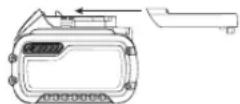
To Attach the Dust Bag
- Fit the dust bag 37 to the dust port 14 as shown in Figure I.
To Empty the Dust Bag
- Remove dust bag 37 from the saw and gently shake or tap the dust bag to empty.
- Reattach the dust bag back onto the dust port 14.
You may notice that all the dust will not come free from the bag. This will not affect cutting performance but will reduce the saw's dust collection efficiency. To restore your saw's dust collection efficiency, depress the spring inside the dust bag when you are emptying it and tap it on the side of the trash can or dust receptacle.
CAUTION: Never operate this saw unless the dust bag or LT dust extractor is in place. Wood dust may create a breathing hazard.
Cutting With Your Saw (Fig. A)
If you cannot secure the workpiece on the table and against the fence by hand (irregular shape, etc.), or your hand would be less than 100mm from the blade, a clamp or other fixture must be used. Refer to Clamping the Workpiece for more information.
If the slide feature is not used, ensure the saw head is pushed back as far as possible and the rail lock knob 20 is tightened. This will prevent the saw from sliding along its rails as the workpiece is engaged.
NOTE: DO NOT CUT METALS OR MASONRY WITH THIS SAW. Do not use any abrasive blades.
NOTE: Refer to Guard Actuation and Visibility in the Adjustments section for important information about the lower guard before cutting.
Crosscuts
Straight Cut (Fig. A, G1, G2)
A crosscut is made by cutting wood across the grain at any angle. A straight crosscut is made with the litre arm at the zero degree position. Set and lock the litre arm at zero, hold the wood firmly on the table and against the fence. With the rail lock knob 20 tightened, turn on the saw by squeezing the trigger switch 1.
When the saw comes up to speed (about 1 second) lower the arm smoothly and slowly to cut through the wood. Let the blade come to a full stop before raising arm.
When cutting anything larger than a 51 mm x 102 mm, use an out-down-back motion with the rail lock knob 20 loosened. Pull the saw out, toward you, lower the saw head down toward the workpiece, and slowly push the saw back to complete the cut. Do not allow the saw blade to contact the top of the workpiece while pulling out. The saw may run toward you, possibly causing personal injury or damage to the workpiece.
WARNING: Always use a work clamp to maintain control and reduce work of workpiece damage and personal injury, if your hands are required to be within 100mm of the blade during the cut.
NOTE: The rail lock knob 20 shown in Figure A must be loose to allow the saw to slide along its rails.
Mitre crosscuts are made with the metre arm at some angle other than zero. This angle is often 45^ for making corners, but can be set anywhere from zero to 48^ left or 48^ right. To metre the saw, loosen the metre lock knob by turning it anticlockwise. Pull up on the metre lock knob to move the metre arm 7 to the metre angle desired on the metre scale 8. Turn the metre lock knob clockwise to tighten. Make the cut as described above.
When performing a litre cut on workpieces wider than 51mm× 102mm that are shorter in length, always place the longer side against the fence (Fig. K).
To cut through an existing pencil line on a piece of wood, match the angle as close as possible. Cut the wood a little too long and measure from the pencil line to the cut edge to determine which direction to adjust the mitre angle and recut. This will take some practice, but it is a commonly used technique.
Bevel Cuts (Fig. L1, L2)
A bevel cut is a crosscut made with the saw blade leaning at an angle to the wood. In order to set the bevel, loosen the bevel lock knob 12, and move the saw to the left as desired. Once the desired bevel angle has been set, tighten the bevel lock firmly. Bevel angles can be set from 0^ right to 48^ left.
To set the bevel angle past 45^ to 48^ ,
- Loosen the bevel lock knob 12.
- Tilt the saw head slightly to slide the bevel override 25 to one side.
- Move the saw head to 48^ .
- Tighten the bevel lock knob.
Quality of Cut
The smoothness of any cut depends on a number of variables. Things like material being cut, blade type, blade sharpness and rate of cut all contribute to the quality of the cut.
When smoothest cuts are desired for molding and other precision work, a sharp (60 tooth carbide tip) blade and a slower, even cutting rate will produce the desired results.
Ensure that the material does not move or creep while cutting; clamp it securely in place. Always let the blade come to a full stop before raising arm. If small fibers of wood still split out at the rear of the workpiece, stick a piece of masking tape on the wood where the cut will be made. Saw through the tape and carefully remove tape when finished.
For varied cutting applications, refer to the list of recommended saw blades for your saw and select the one that best fits your needs. Refer to Saw Blades under Optional Accessories.
Clamping the Workpiece
W F NING: To reduce the risk of serious personal injury, turn off and disconnect battery pack before making any adjustments, performing any cleaning or maintenance, or removing/installing attachments or accessories. An accidental start-up can cause injury.
WARNING: A workpiece that is clamped, balanced and secure a cut may become unbalanced after a cut is completed. An unbalanced load may tip the saw or anything the saw is attached to, such as a table or workbench. When making a cut that may become unbalanced, properly support the workpiece and ensure the saw is firmly bolted to a stable surface. Personal injury may occur.
WARNING: The clamp foot must remain clamped above the base of whenever the clamp is used. Always clamp the workpiece to the base of the saw - not to any other part of the work area. Ensure the clamp foot is not clamped on the edge of the base of the saw.
WARNING: Always use a work clamp to maintain control and reduce the risk of workpiece damage and personal injury, if your hands are required to be within 100mm of the blade during the cut.
EnGLIsH
If you cannot secure the workpiece on the table and against the fence by hand (irregular shape, etc.), or your hand would be less than 100mm from the blade, a clamp or other fixture must be used.
Use the material clamp provided with your saw. To purchase a material clamp, contact your local retailer or DLWALT service centre.
Other aids such as spring clamps, bar clamps or C-clamps may be appropriate for certain sizes and shapes of material. Use care in selecting and placing these clamps. Take time to make a dry run before making the cut.
To Install Clamp (Fig. M)
- With the clamp 38 facing the back of the litre saw, insert the clamp rod into the hole 21 behind the fence. Ensure the groove at the bottom of the clamp rod is fully inserted into the hole 21.
- Rotate the clamp 180^ toward the front of the litre saw.
- Loosen the knob to adjust the clamp arm up or down, then use the fine adjust knob to firmly clamp the workpiece.
NOTE: Place the clamp on the opposite side of the base when beveling. ALWAYS MAKE DRY RUNS (UNPOWERED) BEFORE FINISH CUTS TO CHECK THE PATH OF THE BLADE.ENSURE THE CLAMP DOES NOT INTERFERE WITH THE ACTION OF THE SAW OR GUARDS.
ADJUSTMENTS
WARNING: To reduce the risk of serious personal injury, turn off and disconnect battery pack before making any adjustments, performing any cleaning or maintenance, or removing/installing attachments or accessories. An accidental start-up can cause injury.
Your litre saw is fully and accurately adjusted at the factory at the time of manufacture. If readjustment due to shipping and handling or any other reason is required, follow the instructions below to adjust your saw.
Once made, these adjustments should remain accurate. Take a little time now to follow these directions carefully to maintain the accuracy of which your saw is capable.
Mitre Scale Adjustment (Fig. J, N)
Lock the saw head in the down position. Unlock the metre lock knob 5 and swing the metre arm 7 until it locks at the 0^ metre position. Do not lock the metre lock knob. Place a square against the saw's fence and blade, as shown in Figure N. (Do not touch the tips of the blade teeth with the square. To do so will cause an inaccurate measurement.) If the saw blade is not exactly perpendicular to the fence, loosen the three screws (9, Fig. J) that hold the metre scale 8 and move the metre arm and the scale left or right until the blade is perpendicular to the fence, as measured with the square. Retighten the three screws.
Bevel Square to Table Adjustment (Fig. A, L1, 0)
To align the blade square to the table, lock the operating handle in the down position with the lock down pin 23. Place a square against the blade, ensuring the square is not on top of a tooth. Loosen the bevel lock knob 12 and ensure the bevel arm is firmly against the 0^ bevel stop. Rotate the 0^ bevel adjustment screw 41 with a 4 mm hex key (not provided) as necessary so that the blade is at 0^ bevel to the table, as measured with the square.
Bevel Stop 45^ Left Adjustment (Fig. A, L1, L2)
To adjust the left 45^ bevel stop, first loosen the bevel lock knob and tilt the head until it stops. Verify that the bevel override 25 is in the 45^ position; and if the bevel pointer 40 does not indicate exactly 45^ , turn the 45^ bevel adjustment screw 42 until the bevel pointer 40 reads 45^ .
Guard Actuation and Visibility (Fig. A, X)
CAINTION: Pinch hazard. To reduce the risk of injury, keep thumb underneath the operating handle when pulling the handle down. The lower guard will move up as the operating handle is pulled down, which could cause pinching.
The lower guard 4 on your saw has been designed to automatically uncover the blade when the arm is brought down and to cover the blade when the arm is raised.
Before each use or after making adjustments, cycle the arm (unpowered) and make sure the guard opens smoothly and closes fully. It should not contact the blade. With the arm up, raise the guard (unpowered) as shown in Figure X and release. The guard should fully close rapidly. Do not operate the saw if the guard does not move freely and fully close rapidly. Never clamp or tie the guard in an open position when operating the saw.
The guard can be raised by hand when installing or removing saw blades or for inspection of the saw. NEVER RAISE THE LOWER GUARD MANUALLY UN LESS THE BLADE IS STOPPED.
NOTE: Certain special cuts of large material will require that you manually raise the guard. Refer to Cutting Large Material under Special Cuts.
The front section of the guard is louvered for visibility while cutting. Although the louvers dramatically reduce flying debris, there are openings in the guard and safety glasses should be worn at all times.
Rail Guide Adjustment (Fig. A)
Periodically check the rails 13 for any play or clearance. The rails can be cleaned with a dry clean cloth. The right rail can be adjusted with the rail adjustment screw 19 shown in Figure A. To reduce clearance, use a 4mm hex wrench and rotate the set screw clockwise gradually while sliding the saw head back and forth. Reduce play while maintaining minimum slide force.
Support for Long Pieces
WARNING: To reduce the risk of serious personal injury, turn off and disconnect battery pack before making any adjustments, performing any cleaning or maintenance, or removing/installing attachments or accessories. An accidental start-up can cause injury.
ALWAYs SUPPORT LOng PIEcEs.
Never use another person as a substitute for a table extension, as additional support for a workpiece that is longer or wider than the basic litre saw table or to help feed, support or pull the workpiece.
Support long workpieces using any convenient means such as sawhorses or similar devices to keep the ends from dropping.
Cutting Picture Frames, Shadow Boxes And Other Four-Sided Projects (Fig. P, Q)
To best understand how to make the items listed here, we suggest that you try a few simple projects using scrap wood until you develop a "feel" for your saw.
Your saw is the perfect tool for mitring corners like the one shown in Figure P. Sketch A in Figure Q shows a joint made by using the bevel adjustment to bevel the edges of the two boards at 45^ each to produce a 90^ corner. For this joint the mitre arm was locked in the zero position and the bevel adjustment was locked at 45^ . The wood was positioned with the broad flat side against the table and the narrow edge against the fence. The cut could also be made by mitring right and left with the broad surface against the fence.
Cutting Trim Molding and Other Frames (Fig. Q)
Sketch B in Figure Q shows a joint made by setting the metre arm at 45^ to litre the two boards to form a 90^ corner. To make this type of joint, set the bevel adjustment to zero and the metre arm to 45^ . Once again, position the wood with the broad flat side on the table and the narrow edge against the fence.
Figures P and Q are for four-sided objects only.
As the number of sides changes, so do the metre and bevel angles. The chart below gives the proper angles for a variety of shapes.
| - EXAMPLES - |
| NUMBER OF SIDES MITRE OR BEVEL ANGLE |
| 4 15° |
| 5 36° |
| 6 30° |
| 7 25.7° |
| 8 22.5° |
| 9 20° |
| 10 18° |
The chart assumes that all sides are of equal length. For a shape that is not shown in the chart, use the following formula: 180^ divided by the number of sides equals the litre (if the material is cut vertically) or bevel angle (if the material is cut laying flat).
Cutting Compound Mitres (Fig. R)
A compound litre is a cut made using a litre angle and a bevel angle at the same time. This is the type of cut used to make frames or boxes with slanting sides like the one shown in Figure R.
NOTE: If the cutting angle varies from cut to cut, check that the bevel lock knob and the mitre lock handle are securely locked. These must be locked after making any changes in bevel or mitre.
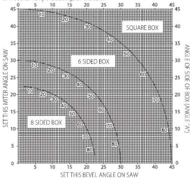
The table below will assist you in selecting the proper bevel and mitre settings for common compound mitre cuts. To use the chart, select the desired angle A (Fig. R) of your project and locate that angle on the appropriate arc in the chart. From that point follow the chart straight down to find the correct bevel angle and straight across to find the correct mitre angle.
Set your saw to the prescribed angles and make a few trial cuts. Practice fitting the cut pieces together until you develop a feel for this procedure and feel comfortable with it.
Example: To make a 4-sided box with 26^ exterior angles (Angle A, Fig. R), use the upper right arc. Find 26^ on the arc scale. Follow the horizontal intersecting line to either side to get mirte angle setting on saw (42^) . Likewise, follow the vertical intersecting line to the top or bottom to get the bevel angle setting on the saw (18^) . Always try cuts on a few scrap pieces of wood to verify the settings on the saw.
Cutting Base Molding (Fig. S)
Straight 90^ cuts:
Position the wood against the fence and hold it in place as shown in
Figure S. Turn on the saw, allow the blade to reach full speed and lower the arm smoothly through the cut.
Cutting Base Molding Up to 89 mm High Vertically Against the Fence
Position material as shown in Figure S.
All cuts should be made with the back of the molding against the fence and with the bottom of the molding against the table.
| INSIDE CORNER OUTSIDE CORNER | |
| Left side Mitre left 45° | Mitre right 45° |
| Save left side of cut | Save left side of cut |
| Right side Mitre right 45° | Mitre left 45° |
| Save right side of cut | Save right side of cut |
Material up to 89mm can be cut as described above. The width of the material cannot exceed 19mm .
Cutting Crown Molding (Fig. T, U)
In order to fit properly, crown molding must be compound mitred with extreme accuracy.
The two flat surfaces on a given piece of crown molding are at angles that, when added together, equal exactly 90^ . Most, but not all, crown molding has a top rear angle (the section that fits flat against the ceiling) of 52^ and a bottom rear angle (the part that fits flat against the wall) of 38^ .
Your litre saw has special pre-set litre detent points at 31.6^ left and right for cutting crown molding at the proper angle. There is also a mark on the bevel scale at 33.8^ .
The Bevel Setting/Type of Cut chart gives the proper settings for cutting crown molding. (The numbers for the litre and bevel settings are very precise and are not easy to accurately set on your saw.) Since most rooms do not have angles of precisely 90^ , you will have to fine tune your settings anyway.
PRETESTING WITH SCRAP MATERIAL IS EXTREMELY IMPORTANT! Instructions for Cutting Crown Molding Laying Flat and Using the Compound Features
- Lay the molding with broad back surface down flat on saw table (Fig. T).
- The settings below are for all Standard (U.S.) crown molding with 52^ and 38^ angles.
| BEVEL SETTING TYPE OF CUT |
| 33.8° LEFT SIDE, INSIDE CORNER: |
| Top of molding against fence |
| Mitre table set right 31.62° |
| Save left end of cut |
| 33.8° RIGHT SIDE, INSIDE CORNER: |
| Bottom of molding against fence |
| Mitre table set left 31.62° |
| Save left end of cut |
| 33.8° LEFT SIDE, OUTSIDE CORNER: |
| Bottom of molding against fence |
| Mitre table set left 31.62° |
| Save right end of cut |
| 33.8° RIGHT SIDE, OUTSIDE CORNER: |
| Top of molding against fence |
| Mitre table set right 31.62° |
| Save right end of cut |
NOTE: When setting bevel and litre angles for all compound mitres, remember that the angles presented for crown moldings are very precise and difficult to set exactly. Since they can easily shift slightly and very few
ENGLISH
rooms have exactly square corners, all settings should be tested on scrap molding.
PRETESTING WITH SCRAP MATERIAL IS EXTREMELY IMPORTANT!
Alternative method for Cutting Crown Molding
Place the molding at an angle between the fence 11 and the saw table 43, as shown in Figure U.
The advantage to cutting crown molding using this method is that no bevel cut is required. Minute changes in the mitre angle can be made without affecting the bevel angle. This way, when corners other than 90^ are encountered, the saw can be quickly and easily adjusted for them.
Instructions for Cutting Crown Molding Angled Between the Fence and Base of the Saw for All Cuts
This saw can cut up to 14 mm x 92 mm crown molding nested.
- Place the molding at an angle between the fence 11 and the saw table 43, as shown in Figure U.
- The angled "flats" on the back of the molding must rest squarely on the fence and saw table.
BLADE DESCRIPTIONS
APPLICATION DIAMETER TEETH
General Purpose 184 mm 40
Fine Woodcutting 184 mm 60
| INSIDE CORNER OUTSIDE CORNER | |
| Left side Mitre right at 45° | Mitre left at 45° |
| Save right side of cut | Save right side of cut |
| Right side Mitre left at 45° | Mitre right at 45° |
| Save left side of cut | Save left side of cut |
Special Cuts
NEVER MAKE ANY CUT UNLESS THE MATERIAL IS SECURED ON THE TABLE AND AGAINST THE FENCE.
Bowed Material (Fig. V, W)
When cutting bowed material always position it as shown in Figure V and never like that shown in Figure W. Positioning the material incorrectly will cause it to pinch the blade near the completion of the cut.
Cutting Round Material
ROUND MATERIAL SHOULD BE CLAMPED OR HELD FIRMLY TO THE FENCE TO KEEP IT FROM ROLLING. This is extremely important when making angle cuts.
Cutting Large Material (Fig. X)
Occasionally you will encounter a piece of wood a little too large to fit beneath the lower guard. To clear the guard over the wood, with the saw off and your right hand on the operating handle, place your right thumb outside of the upper portion of the guard and roll the guard up just enough to clear the wood, as shown in Figure X. Release the guard prior to starting the motor. The guard mechanism will function properly during the cut. Only do this when necessary. NEVER TIE, TAPE, OR OTHERWISE HOLD THE GUARD OPEN WHEN OPERATING THIS SAW.
MAINTENANCE
Your DEWALT power tool has been designed to operate over a long period of time with a minimum of maintenance. Continuous satisfactory operation depends upon proper tool care and regular cleaning.
WARNING: To reduce the risk of serious personal injury, turn off and disconnect battery pack before making any adjustments, performing any cleaning or maintenance, or removing/installing attachments or accessories. An accidental start-up can cause injury.
The charger and battery pack are not serviceable.

Lubrication
Your power tool requires no additional lubrication.

Cleaning
WARNING: Blow dirt and dust out of the main housing with dry air. Even as dirt is seen collecting in and around the air vents. Wear approved eye protection and approved dust mask when performing this procedure.
WARNING: Never use solvents or other harsh chemicals for cleaning the non-metallic parts of the tool. These chemicals may weaken the materials used in these parts. Use a cloth dampened only with water and mild soap. Never let any liquid get inside the tool; never immerse any part of the tool into a liquid.
Optional Accessories
WARNING: Since accessories, other than those offered by DEWALT, may not be tested with this product, use of such accessories with this tool could be hazardous. To reduce the risk of injury, only DEWALT recommended accessories should be used with this product..
The following accessories, designed for your saw, may be helpful. In some cases, other locally obtained work supports, length stops, clamps, etc., may be more appropriate. Use care in selecting and using accessories. Consult your dealer for further information on the appropriate accessories.
Saw Blades
ONLY USE 184 mm SAW BLADES WITH 16 mm DIAMETER ROUND ARBOR HOLES and a maximum KERF of 2.1 mm. SPEED RATING MUST BE AT LEAST 4000 RPM. DO NOT USE BLADES WITH DIAMOND-SHAPED ARBOR HOLES. Never use a different diameter blade. It will not be guarded properly. Use crosscut blades only! Do not use blades designed for ripping, combination blades or blades with hook angles in excess of 7^ .
Protecting the Environment

Separate collection. Products and batteries marked with this symbol must not be disposed of with normal household waste. Products and batteries contain materials that can be recovered or recycled reducing the demand for raw materials. Please recycle
electrical products and batteries according to local provisions. Further information is available at www.2helpU.com.
Rechargeable Battery Pack
This long life battery pack must be recharged when it fails to produce sufficient power on jobs which were easily done before. At the end of its technical life, discard it with due care for our environment:
- Run the battery pack down completely, then remove it from the tool.
- Li-ion cells are recyclable. Take them to your dealer or a local recycling station. The collected battery packs will be recycled or disposed of properly.
Troubleshooting Guide BE SURE TO FOLLOW SAFETY RULES AND INSTRUCTIONS
TROUBLE WHAT'S WROng? WHAT TO DO
| Saw will not start | Battery not installed | Install battery. Refer to Installing and Removing Battery Pack. |
| Battery not charged Charge battery. Refer to Charging Procedure. | ||
| Brushes worn out Have brushes replaced by authorised service centre. | ||
| Saw makes unsatisfactory cuts | Dull blade Replace blade. Refer to Changing or Installing a New Saw Blade. | |
| Blade mounted backwards | Turn blade around. Refer to Changing or Installing a New Saw Blade. | |
| Gum or pitch on blade Remove blade and clean with coarse steel wool and turpentine or household oven cleaner. | ||
| Incorrect blade for work being done | Change the blade type. Refer to Saw Blades under Optional Accessories. | |
| XPS™ worklight is flashing | Battery not charged | Charge battery. Refer to Charging Procedure. |
| Machine vibrates excessively | Saw not mounted securely to stand or work bench | Tighten all mounting hardware. Refer to Bench Mounting. |
| Stand or bench on uneven floor | Reposition on flat level surface. Refer to Familiarization. | |
| Damaged saw blade | Replace blade. Refer to Changing or Installing a New Saw Blade. | |
| Does not make accurate metre cuts | Mitre scale not adjusted correctly | Check and adjust. Refer to Mitre Scale Adjustment under Adjustments. |
| Blade is not square to fence | Check and adjust. Refer to Mitre Scale Adjustment under Adjustments. | |
| Blade is not perpendicular to table | Check and adjust fence. Refer to Bevel Square to Table Adjustment under Adjustments. | |
| Workpiece moving | Clamp workpiece securely to fence or glue 120 grit sandpaper to fence with rubber cement. | |
| Kerf plate worn or damaged | Take to authorised service centre. | |
| Material pinches blade | Cutting bowed material | Refer to Bowed Material under Special Cuts. |
SIERRA INGLETADORA COMPUESTA DESLIZANTE SIN CABLE DCS365
Enhorabuena!
| Lado izquierdo Inglete a 45°a la izquierda | Inglete a 45°a la referencia |
| Guarde el lado izquierdo del corte | Guarde el lado izquierdo del corte |
| Lado correcho Inglete a 45°a la referencia | Inglete a 45°a la izquierda |
| Guarde el lado referencia del corte | Guarde el lado referencia del corte |
| El material de hasta 89 mm pueda cortarse como se indica arriba. El ancho del material noSEOSEOSEOSEOSEOSEOSEOSEOSEOSEOSEOSEOSEOSEOSEOSEOSEOSEOSEOSEOSEOSEOSEOSEOSEOSEOSEOSEOSEOSEOSEOSEOSEOSEOSEOSEOSEOSEOSEOSEOSEOSEOSEOSEOSEOSEOSEOSEOSEOSEOSEOSEOSEOSEOSEOSEOSEOSEOSEOSEOSEOSEOSEOSEOSEOSEOSEOSEOSEOSEOSEOSEOSEOSEOSEOSEOSEOSEOSEOSEOSEOSEOSEOSEOSEOSEOSEOSEOSEOSEOSEOSEOSEOSEOSEOSEOSEOSEOSEOSEO SEOSEOSEOSEOSEOSEOSEOSEOSEOSEOSEOSEOSEOSEOSEOSEOSEOSEOSEOSEOSEOSEOSEOSEOSEOSEOSEOSEOSEOSEOSEOSEOSEOSEOSEOSEOSEOSEOSEOSEOSEOSEOSEOSEOSEOSEOSEOSEOSEOSEOSEOSEOSEOSEOSEOSEOSEOSEOSEOSEOSEOSEOSEOSEOSEOSEOSEOSEOSEOSEOSEOSEOSEOSEOSEOSEOSEOSEOSEOSEOSEOSEOSEOSEOSEOSEOSEOSEOSEOSEOSEOSEOSEOSEOSEOSEOSEOSEOSEOSEOseoSEOSEOSEOSEOSEOSEOSEOSEOSEOSEOSEOSEOSEOSEOSEOSEOSEOSEOSEOSEOSEOSEOSEOSEOSEOSEOSEOSEOSEOSEOSEOSEOSEOSEOSEOSEOSEOSEOSEOSEOSEOSEOSEOSEOSEOSEOSEOSEOSEOSEOSEOSEOSEOSEOSEOSEOSEOSEOSEOSEOSEOSEOSEOSEOSEOSEOSEOSEOSEOSEOSEOSEOSEOSEOSEOSEOSEOSEOSEOSEOSEOSEOSEOSEOSEOSEOSEOSEOSEOSEOSEOSEOSEOSEOSEOSEOSEOSEOSEOSEQEOSEOSEOSEOSEOSEOSEOSEOSEOSEOSEOSEOSEOSEOSEOSEOSEOSEOSEOSEOSEOSEOSEOSEOSEOSEOSEOSEOSEOSEOSEOSEOSEOSEOSEOSEOSEOSEOSEOSEOSEOSEOSEOSEOSEOSEOSEOSEOSEOSEOSEOSEOSEOSEOSEOSEOSEOSEOSEOSEOSEOSEOSEOSEOSEOSEOSEOSEOSEOSEOSEOSEOSEOSEOSEOSEOSEOSEOSEOSEOSEOSEOSEOSEOSEOSEOSEOSEOSEOSEOSEOSEOSEOSEOSEOSEOSEOSEOSEOSEOEOSEOSEOSEOSEOSEOSEOSEOSEOSEOSEOSEOSEOSEOSEOSEOSEOSEOSEOSEOSEOSEOSEOSEOSEOSEOSEOSEOSEOSEOSEOSEOSEOSEOSEOSEOSEOSEOSEOSEOSEOSEOSEOSEOSEOSEOSEOSEOSEOSEOSEOSEOSEOSEOSEOSEOSEOSEOSEOSEOSEOSEOSEOSEOSEOSEOSEOSEOSEOSEOSEOSEOSEOSEOSEOSEOSEOSEOSEOSEOSEOSEOSEOSEOSEOSEOSEOSEOSEOSEOSEOSEOSEOSEOSEOSEOSEOSEOSEOEO SEOSEOSEOSEOSEOSEOSEOSEOSEOSEOSEOSEOSEOSEOSEOSEOSEOSEOSEOSEOSEOSEOSEOSEOSEOSEOSEOSEOSEOSEOSEOSEOSEOSEOSEOSEOSEOSEOSEOSEOSEOSEOSEOSEOSEOSEOSEOSEOSEOSEOSEOSEOSEOSEOSEOSEOSEOSEOSEOSEOSEOSEOSEOSEOSEOSEOSEOSEOSEOSEOSEOSEOSEOSEOSEOSEOSEOSEOSEOSEOSEOSEOSEOSEOSEOSEOSEOSEOSEOSEOSEOSEOSEOSEOSEOSEOSEOSEOSEOEO | |
Corte de molduras de corona (Fig. T, U)
(Isolation double) - outfits
sOUTEnEZ TOUJOURs LEs PIEcEs LoNGUEs.
COIN INTÉRIEUR COIN EXTERIEUR
Batterie rechargeable
BEWAAR ALLE WAARSCHUWINGEN EN INSTRUCTIES ALS TOEKOMSTIG REFERENTIEMATERIALAAL
Stovsuging (Fig. A, I)
INNVENDIG HJØRNE UTVENDIG HJØRNE
Director de Engenharia
D-65510, Idstein, Germany
30.10.2015

21 Hal for skruvtving
16 Batteripaket
22 Klingnyckel
AIATHPHE TIE IPOEIOIHOHSEI KAI TIE OAHHIEI A MEANONTIKH ANAOPA
O opoc nEeKtpko epyaleio oE oec tic npoedonnoieic, avapeptai oE epyaleio nou tpofooteiia me peuana to nEeKtpko diktuo (e KaWdo) nOe epyaleio nou kienoupyei e pnatapia (aovpuato).
H matapia DEWALT FLEXVOLT* diaTei duo kataotaeic; Xponc kal Metapopac.
Kataotaon Xpohc: Otav n mntapia FLEXVOLTM ev exe tonoetne 0e npoiov exe tonoetne 0e npoiov DEWALT 18 V, 0a leioupeoy eov mntatopia 18 V. Otav n mntatipia FLEXVOLTM exe tonoetne 0e npoiov 54 V n 108 V (6oo npatipow tuv 54 V), 0a leoupeoy oav mntatipia 54 V.
Kataotaon Metaopac: Otav exi totoeetnei to kanaki otnymuatapia FLEXVOLT, n mpatia eivai oe katotaon metaopac. DuAaTe to kanaki ia thy nepiTTwn metaopac.
Otav eivai oke tataoan Metaopac,oi oeipc Tuv kuueaw eivai nAektpiKa anouovdeievec eoao tonaketo mntapiac, ae anotetaeqa va Eomegaitai
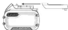
3 pnataiee e xanlntepn ovmaotik n TmuBawv (Wh) avti yia 1
unatapia e uynlntepn ovmaotik n TmuBawv. Autn aauenveyn
noootnta wv 3 npataipw v t n meiwv n ovmaotik n TmuBawv
uopei va kavei epiktn thv ecaipeon tou naKetou natapiw ano
opiaevouc kavoviaouc metaqopow nou eniabovtai otic natapiec e
ylnlntepn ovmaotik n TmuBawv.
Tia napadeiyua, n tui Wh Metapopac utopei va elai 3 x 36 Wh, nou anpaivei
Napabeiyua onuavonxpnongkai metaopacOTYETIKETA
3 matapiec tuv 36 Wh n pia. H tiun Wh Xponc umopei va eivai 108 Wh (unovoeitr 1 matapia).

Use:108 Wh Transport:3x36 Wh
UoTaoeic yia tnv anoHkeuon
-
To kaLTepo mepoc aTOnhKeuong evai eva dpoe kai oTey voepoc, paKpia an to aMeao nlaikoc kai TnV uNepBoAikn cToTn npuo. Ia BcIaTn anooan kai diapkeia cWnc, aOnhKeueTE tic mntapiec oe Thepuokpaia domegaiaouavdewTic xpnipoioteiE.
-
Ia yéyálo xpóvo φuλaεnc, yia ta kalutepa anotéλeouata ouviotatai va anθηkeuεte to naketo μntapuiw πnpuoc φoptiαevo, oδρoερó, Εnpó μερoc, εκτος tou φoptiσπh.
SHMEIOsH:Ta naketo npataipwov 8v 0a npenei va anothekuovtai TEeiooc ekopoptiaeva.To naketo npataipw 0a xpeiaotei va enavoopoptei npiv tn xpnan.
EtiketeC OTo φoptiOn kai Tny μnatapia
Emieovtwv EIKOVpypaTuW TNOXPnOIOIOuVT ATO EYxepidio auto, OI EtKETc NwV OTo qopTOn KAI OTo NaKETO MAtapiW Muopei va 6eivouv Ta Enc EIKOVpyaMuata:

AiaBaeToeyxepiioo8nyiwvpiiv an to xpan.

AvatpeEteotaTeyivka yia to xpovo opionc.

MnV ayyicTe me ayuyiua avtikepeva.

Mn poptiEe KATEOTpauevecmuTapieC.

Naany EKtiBetal e vepo.

ΦoovtεTE yia tny aoeon avikatαaon tuxov λattuμatikw kaωδiuv.

H φóption va yivetai μovo oE θερμοκραδia ano 4°C ἐως 40°C.

Móvo yia xipnoe eowtepiokxwpo.

AnoppiTe Tn mataiae PioK npoc To piaov tpo.

Φopticetata naKeta μnataipiWDeWALT mOvo μe touc πoβλεπομeouc φoptiotec DiWALT. H φoption naketuw μnataipw aawv ano tic npoβλεπoEvEc μnatapiec DeWALT μe xonon φoptiotn DIWALT mOpei va npokalaei ekpnEi touc n dAec EIKIVDueC kataotaeic.

Mny netae to naKeto mataipwOe pwnia.

XPHSH (xwpi kanaik aetapopac).napadeyua: H tui Wh evai 108 Wh (1 nataipia u 108 Wh).

METADOPA (eEvouwpatuwévo kanaki μetapopac). Napδεiyμa: H tɪŋ Wh εivai 3 x 36 Wh (3 μntatapiec, twv 36 Wh).
Tunoc matapaw
To DCS365eitoupyei e naKeto unatapiw Tov 18 V.
Auta ta naeketa nataapw mnpov va xnpoiopoinoov: DCB141, DCB142, DCB143, DCB144, DCB145, DCB181, DCB182, DCB183, DCB183B, DCB184, DCB184B, DCB185. Ta nepoootepe c npopopiec avatpeTe o Tevika 6e0eva.
Neplexóvea oukeuaia
Daatookec (Eik. L1, L2)
Mia paTaokaonn Eivai ma Ekykapoi Ka nou yivetai ne T aenida npiovou oKian wnpoc to ELO. Tia va puOmuete tn paTaokaon, 1aakapete To koupi aopalanc qAtaokaonnc 12 KAI petaivnte To npov npoc Ta apiotepa otwC xpeiaCTai Apou ExTe puBmuEi T yvia paTaokaonnc opie Te Nv aopalanc qAtaokaonnc kaA. Oiyuieq paTaokaonnc mnpovva puBmuotuv an 0eEja euc 48o apiotepa.
Tva paogpiaete nty yuivia paaltookonnc nepav tuv 45euc tic 48o
- Xalapawot To koupi pueuian caaataokn 12.
- FepTe Tny KepaTou npioov Eaopa yia va oupeTe Tny npakapn paTaocokonc 25 onn nAeupa
- Metakivto Tny KepaTou npipovot48
- ΣφiEτοΚουμιασρλίοης φαλΤΟΚΟΙΝίς
Noiotnta tnc konnc
H ouaotnta oniaodnoote konnc eapatai an evav apibu maetanv. Napayovtec onw to eioac tou uakou nou kobetai, o tonoc tnac aeidac, naunpota tnc aeidac kal tauxutnkaonc, ooioubetaauov onny noiota tnc konnc.
Oraanravtai niaqaic konie, yia dnoupyia kopvivkai yia aalec epyaiaac akbetaiac, 8a exete ta eniogunnta anoteleouata av xonounanae tia aixunotienia (60 doviw v e m npkapbiou) kai evnio apyo, opoioooppoo puho ko.
Bebaiwtheta otu uikov dev kivei tai n oiaoalvei metakivei tai katn kn. Tpeewote to kaad otn theou.Aqvete navt n aeilda va otauatnoe teleicnpiv avuwoeto bpaxiova.
Av otny niaw nlaevpa Tou tepaxiou epyaiae Eekoauouvva diaywipocvatmupec ivec Euaou, koiotse eva koumuatkioknac xaptotaiviac oto Eao ekel nou oyaiyinei konn. Ekteolee tvknn poe aTnv taivia kqapapeote npoektiknTv tavia otav teaeioeTe.
Tia tic diapopoe cepapoyc koinc, avatpeTe ot nlaota tw ovuiotwewv wienov npioviou 6ioka yia to npiov oac kal mleTe autn nou taipiae Kauteepa otic avaykeocac AvatpeTe oto tmuAenidec npioiuotnv Evontna Ppoaipetika eaooup.

- Miljobeskyttelese
- EC-Declaration of Conformity
- Machinery Directive
- Cordless Sliding Compound Mitre Saw DCS365
- Definitions: Safety Guidelines
- General Power Tool SafetyWarnings
- SAVE ALL WARNING AND INSTRUCTIONS FOR FUTURE REFERENCE
- 1) Work area safety
- 2) Electrical safety
- 3) Personal safety
- 4) Power tool use and care
- 5) Battery tool use and care
- EnGLIsH
- 6) Service
- Safety Instructions for Mitre Saws
- Additional Safety Rules for Mitre Saws
- Residual Risks
- SAVE THESE INSTRUCTIONS
- Chargers
- Electrical Safety
- Mains Plug Replacement (U.K. & Ireland Only)
- Using an Extension Cable
- Important Safety Instructions for All Battery Chargers
- Charging a Battery (Fig. B)
- Charger Operation
- Hot/Cold Pack Delay
- Electronic Protection System
- Wall Mounting
- Charger Cleaning Instructions
- Battery Packs
- Important Safety Instructions for All Battery Packs
- READ ALL INSTRUCTIONS
- Transportation
- Transporting the FLEXVOLT™ Battery
- Storage Recommendations
- Labels on Charger and Battery Pack
- Battery Type
- Package Contents
- Markings on Tool
- Date Code Position (Fig. A)
- Description (Fig. A)
- Intended Use
- ASSEMBLY AND ADJUSTMENTS
- Inserting and Removing the Battery Pack from the Tool (Fig. C)
- To Install the Battery Pack into the Tool Handle
- To Remove the Battery Pack from the Tool
- Fuel Gauge Battery Packs (Fig. C)
- Familiarization (Fig. A, D, E)
- Installing Side Handles (Fig. E)
- Bench Mounting (Fig. A)
- Changing or Installing a New Saw Blade (Fig. F1-F3)
- CAUTION:
- Removing the Blade (Fig. A, C, F1-3)
- Installing a Blade (Fig. C, F1-F3)
- Transporting the Saw (Fig. A)
- Storage of Mitre Saw
- FEATURES AND CONTROLS
- Use of XPS™ LED Worklight System (Fig. A)
- Mitre Lock Knob (Fig. A, J)
- Bevel Lock Knob (Fig. A, L1, L2)
- Rail Lock Knob (Fig. A)
- Lock Down Pin (Fig. A)
- OPERATION
- Instructions for Use
- Proper Body and Hand Position (Fig. G1-G4)
- Trigger Switch (Fig. H)
- Dust Extraction (Fig. A, I)
- To Attach the Dust Bag
- To Empty the Dust Bag
- Cutting With Your Saw (Fig. A)
- Crosscuts
- Straight Cut (Fig. A, G1, G2)
- Bevel Cuts (Fig. L1, L2)
- Quality of Cut
- Clamping the Workpiece
- To Install Clamp (Fig. M)
- ADJUSTMENTS
- Mitre Scale Adjustment (Fig. J, N)
- Bevel Square to Table Adjustment (Fig. A, L1, 0)
- Bevel Stop 45° Left Adjustment (Fig. A, L1, L2)
- Guard Actuation and Visibility (Fig. A, X)
- Rail Guide Adjustment (Fig. A)
- Support for Long Pieces
- ALWAYs SUPPORT LOng PIEcEs.
- Cutting Picture Frames, Shadow Boxes And Other Four-Sided Projects (Fig. P, Q)
- Cutting Trim Molding and Other Frames (Fig. Q)
- Cutting Compound Mitres (Fig. R)
- Cutting Base Molding (Fig. S)
- Cutting Base Molding Up to 89 mm High Vertically Against the Fence
- Cutting Crown Molding (Fig. T, U)
- PRETESTING WITH SCRAP MATERIAL IS EXTREMELY IMPORTANT! Instructions for Cutting Crown Molding Laying Flat and Using the Compound Features
- Alternative method for Cutting Crown Molding
- Instructions for Cutting Crown Molding Angled Between the Fence and Base of the Saw for All Cuts
- Special Cuts
- Bowed Material (Fig. V, W)
- Cutting Round Material
- Cutting Large Material (Fig. X)
- MAINTENANCE
- Lubrication
- Cleaning
- Optional Accessories
- Saw Blades
- Protecting the Environment
- Rechargeable Battery Pack
- SIERRA INGLETADORA COMPUESTA DESLIZANTE SIN CABLE DCS365
- Enhorabuena!
- Corte de molduras de corona (Fig. T, U)
- sOUTEnEZ TOUJOURs LEs PIEcEs LoNGUEs.
- Batterie rechargeable
- BEWAAR ALLE WAARSCHUWINGEN EN INSTRUCTIES ALS TOEKOMSTIG REFERENTIEMATERIALAAL
- Stovsuging (Fig. A, I)
- AIATHPHE TIE IPOEIOIHOHSEI KAI TIE OAHHIEI A MEANONTIKH ANAOPA
- UoTaoeic yia tnv anoHkeuon
- EtiketeC OTo φoptiOn kai Tny μnatapia
- Tunoc matapaw
- Neplexóvea oukeuaia
- Daatookec (Eik. L1, L2)
- Noiotnta tnc konnc
Brand : DEWALT
Model : DCS365N
Category : Saw