
DCMBC723 - Saw DEWALT - Free user manual and instructions
Find the device manual for free DCMBC723 DEWALT in PDF.

| Product type | Clearing saw (grass trimmer, brushcutter) |
| Brand | DeWalt |
| Model | DCMBC723 |
| Nominal voltage | 54 V DC |
| Battery type | Li-Ion (compatible with DCB546, DCB547, DCB548, DCB549) |
| Maximum no-load speed | 5100 rpm |
| Blade width | 25 cm (254 mm) |
| Weight (without battery and accessories) | 6.4 kg |
| Sound pressure level (LpA) at no load | 86 dB(A) |
| Sound power level (LWA) at no load | 100 dB(A) |
| Sound uncertainty (K) | 3.0 dB |
| Emitted vibrations (ah) | 4.6 m/s² |
| Vibration uncertainty (K) | 1.5 m/s² |
| Speed modes | ECO, Standard, Turbo |
| Package contents | Saw, handlebar, blade, guard, axle plate, flange nut, pin, blade key, locking pin, shoulder strap, manual |
| Compatible accessories | Blade to line conversion kit DT20695-QZ, line to blade conversion kit DT20904-QZ |
| Recommended replacement blade | DeWalt DT20696 (diameter 254 mm) |
| Lubrication | Every 100 hours of use with DeWalt 30301914 grease |
| Intended use | Professional lawn and garden maintenance (grass cutting, brush clearing, small trees up to 40 mm) |
| Sound power guarantee | 96 dB(A) according to directive 2000/14/EC |
| Recommended operating temperature | 4 °C to 40 °C |
Frequently Asked Questions - DCMBC723 DEWALT
User questions about DCMBC723 DEWALT
0 question about this device. Answer the ones you know or ask your own.
Ask a new question about this device
Download the instructions for your Saw in PDF format for free! Find your manual DCMBC723 - DEWALT and take your electronic device back in hand. On this page are published all the documents necessary for the use of your device. DCMBC723 by DEWALT.
USER MANUAL DCMBC723 DEWALT
English (original instructions) 26
natural_image
Icon of a person using a laptop inside a black circle (no text or symbols)Fig. A
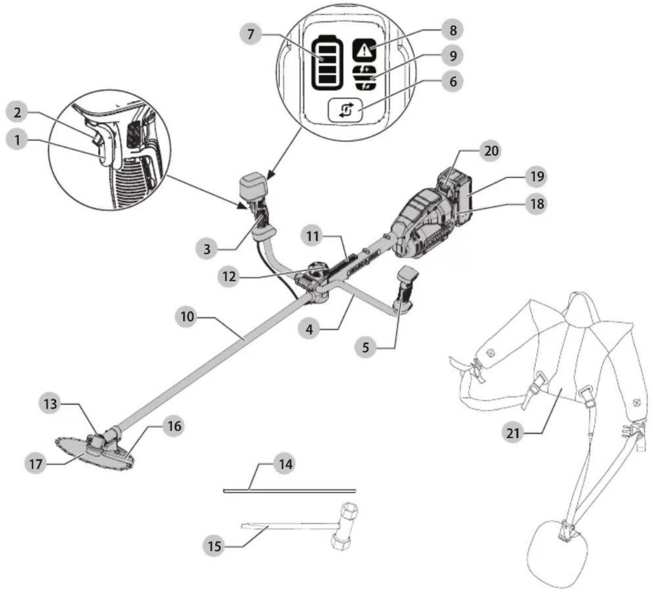
Fig. B Fig. C
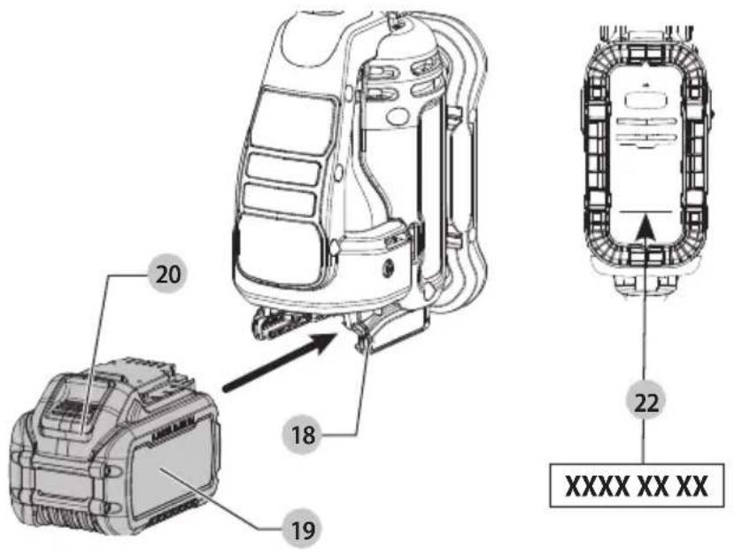
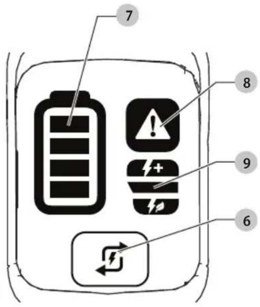
Fig. D
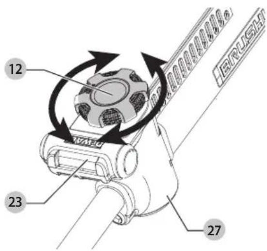
Fig. E
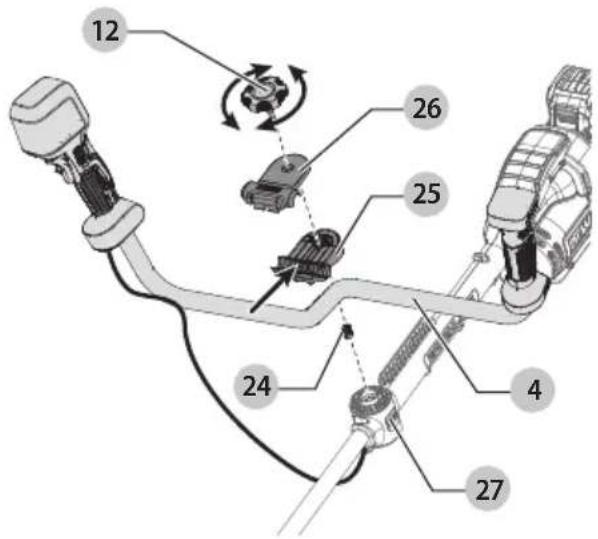
Fig. F
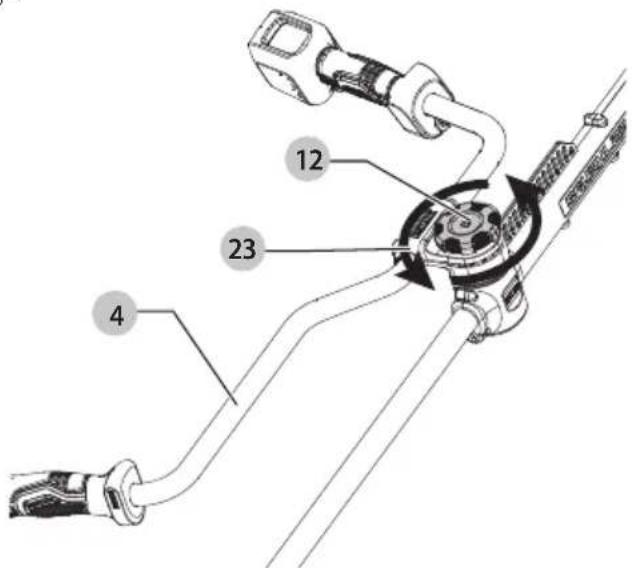
Fig. G
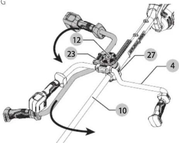
Fig. H
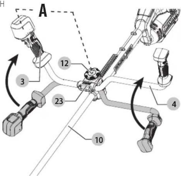
Fig.1
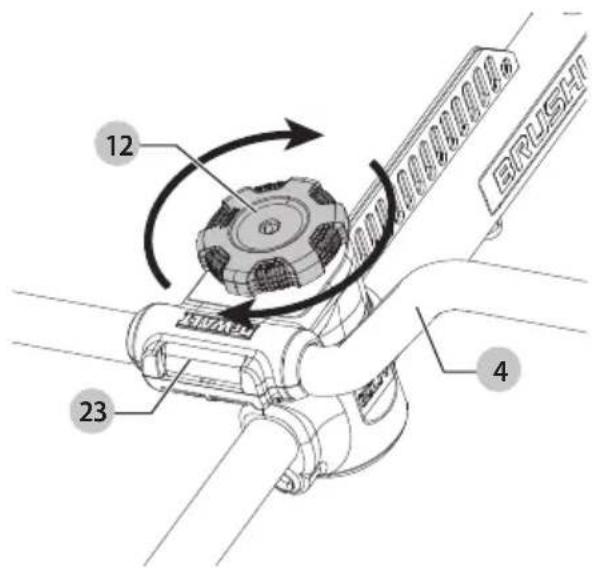
Fig. J Fig. K
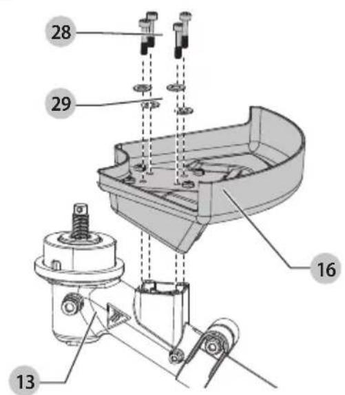
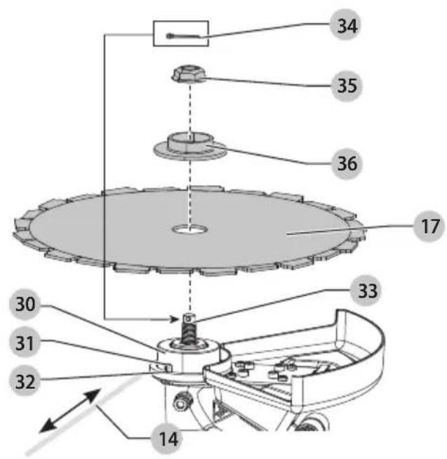
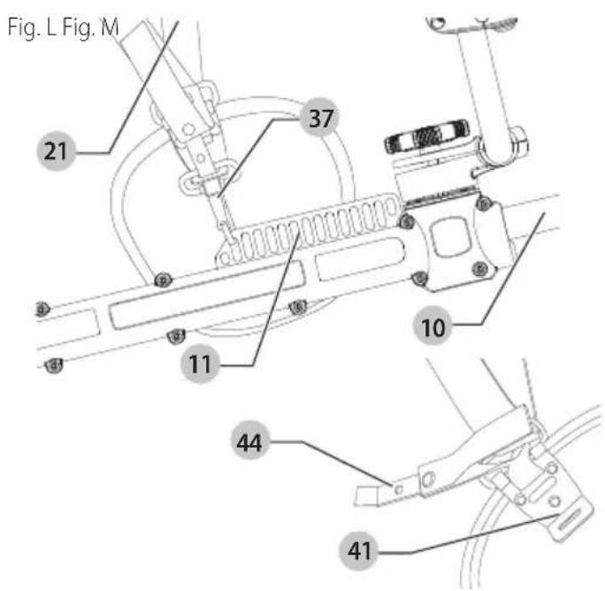
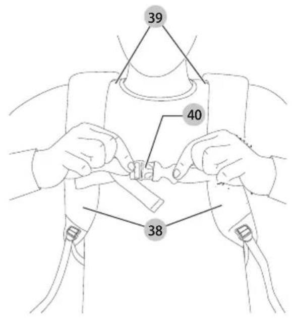
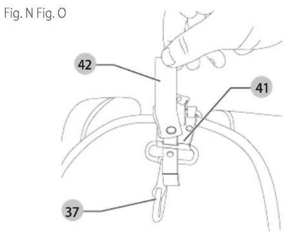
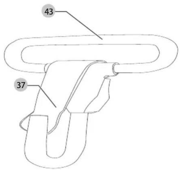
Fig. P Fig. Q
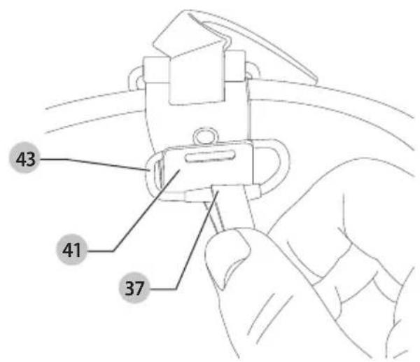
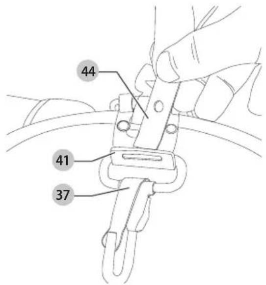
Fig. R Fig. S

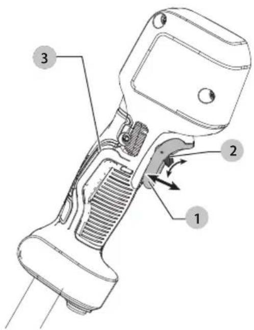
Fig. T Fig. U


Fig. V Fig. W
natural_image
Line drawing of a person holding a device with a black X mark, no text or symbols present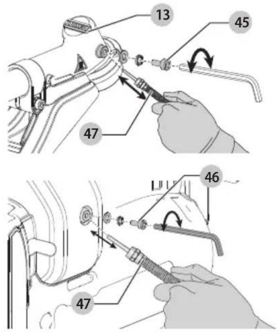
54V SKOVRYDNINGSSAV
DCMBC723

natural_image
Diagram of a mechanical or fluid system with a circular component and directional arrows, no text or symbols present.natural_image
Diagram of a circular mechanical or environmental system with directional arrows and a circular component, no text or symbols present.VEDLIGEHOLDELSE
Vice-President Engineering, PTE-Europe
natural_image
Diagram of a mechanical or electrical component with a circular arrow indicating rotation, showing internal structure and directional arrows (no text or symbols)natural_image
Diagram of a mechanical or electrical component with no visible text, numbers, or symbols.WARTUNG
WARNING: Read all safety warnings, instructions, illustrations, and specifications in this manual before using the machine, including the battery and charger sections provided in an original tool manual or the separate Batteries and Chargers manual. Manuals can be obtained by

contacting Customer Service (refer to the back page of this manual).
Technical Data
| DCMBC723 | ||
| Voltage V | DC | 54 |
| Type 1 | ||
| Battery type Li-Ion | ||
| Maximum speed /min 5100 | ||
| Cutting blade width cm 25 | ||
| Weight (without the battery, cutting accessory, cutting accessory cover, harness and hip pad) | kg 6.4 | |
| L_pA (emission sound pressure level at no load) dB(A) 86 | ||
| L_WA (sound power level at no load) | dB(A) 100 | |
| K(uncertainty for the given sound level) | dB | 3.0 |
| Vibration emission value a_h = | m/s2 | 4.6 |
| Uncertainty K = | m/s2 | 1.5 |
Approved accessories for use with DCMBC723
| DT20695-QZBrush to stringconversion kit,measured in no-loadaccording to 2000/14/EC and EN 62841-1 &IEC 62841-4-4 | L_pA (emission sound pressure level at no load): 83 dB(A)K (uncertainty for the given emission sound pressure level): 3 dB(A) L_WM (sound power level at no load): 94 dB(A)K (uncertainty for the given sound power level): 1.6 dB(A)Vibration emission value a_F: 3.9 m/s^2 Uncertainty K: 1.5 m/s^2 |
| DT20904-QZString to BrushConversion Kit,measured in no-loadaccording to EN62841-1 and IEC62841-4-4 | L_pA (emission sound pressure level at no load): 84 dB(A)K (uncertainty for the given emission sound pressure level): 3 dB(A) L_WM (sound power level at no load): 94 dB(A)K (uncertainty for the given sound power level): 3 dB(A)Vibration emission value a_F: 4.9 m/s^2 Uncertainty K: 1.5 m/s^2 |
The vibration and/or noise emission level given in this information sheet has been measured in accordance with a standardised test given in EN62841 and may be used to compare one tool with another. It may be used for a preliminary assessment of exposure.
WARNING: The declared vibration and/or noise emission level represents the main applications of the tool. However, if the tool is used for different applications, with different accessories or is poorly maintained, the vibration and/or noise emission may differ. This may significantly increase the exposure level over the total working period. An estimation of the level of exposure to vibration and/or noise should also take into account the times when the tool is switched off or when it is running but not actually doing the job. This may significantly reduce the exposure level over the total working period.
Identify additional safety measures to protect the operator from the effects of vibration and/or noise such as: maintain the tool and the accessories, keep the hands warm (relevant for vibration), organisation of work patterns.
EC-Declaration of Conformity Machinery Directive

FORESTRY CLEARING SAW DCMBC723
DT20695-QZ (Brush to String Conversion Kit) DT20904-QZ (String to Brush Conversion Kit)
DEWALT declares that these products described under Technical Data are in compliance with: 2006/42/EC, EN 62841-1:2015 + A11:2022; EN ISO 12100:2010; partly of EN ISO 11806-1:2022.
2000/14/EC, String trimmer after use the String Conversion Kit, item 33, L <50cm, Annex VIII,
TÜV Rheinland LGA Products GmbH
90431 Nürnberg Germany
Notified Body ID No.: 0197
L_WA (measured sound power level) 94 dB,
L_WA (guaranteed sound power) 96 dB.
These products also comply with Directive 2014/30/EU and 2011/65/EU. For more information, please contact DEWALT at the following address or refer to the back of the manual.
The undersigned is responsible for compilation of the technical file and makes this declaration on behalf of DEWALT.

Markus Rompel
Vice-President Engineering, PTE-Europe
65510, Idstein, Germany
08.11.2024

WARNING: To reduce the risk of injury, read the instruction manual.
Definitions: Safety Guidelines
The definitions below describe the level of severity for each signal word. Please read the manual and pay attention to these symbols.
▲ANGER: Indicates an imminently hazardous situation which, if not avoided, will result in death or serious injury.
WARNING: Indicates a potentially hazardous situation which, if not avoided, could result in death or serious injury.
CAUTION: Indicates a potentially hazardous situation which, if not avoided, may result in minor or moderate injury.
NOTICE: Indicates a practice not related to personal injury which, if not avoided, may result in property damage.
Denotes risk of electric shock.
Denotes risk of fire.
GENERAL POWER TOOL SAFETY WARNINGS
WARNING: Read all safety warnings, instructions, illustrations and specifications provided with this power tool. Failure to follow all instructions listed below may result in electric shock, fire and/or serious injury.
SAVE ALL WARNINGS AND INSTRUCTIONS FOR FUTURE REFERENCE
The term "power tool" in the warnings refers to your mains-operated (corded) power tool or battery-operated (cordless) power tool.
1) Work Area Safety
a) Keep work area clean and well lit. Cluttered or dark areas invite accidents.
b) Do not operate power tools in explosive atmospheres, such as in the presence of flammable liquids, gases or dust. Power tools create sparks which may ignite the dust or fumes.
c) Keep children and bystanders away while operating a power tool. Distractions can cause you to lose control.
2) Electrical Safety
a) Power tool plugs must match the outlet. Never modify the plug in any way. Do not use any adapter plugs with earthed (grounded) power tools. Unmodified plugs and matching outlets will reduce risk of electric shock.
b) Avoid body contact with earthed or grounded surfaces, such as pipes, radiators, ranges and refrigerators. There is an increased risk of electric shock if your body is earthed or grounded.
c) Do not expose power tools to rain or wet conditions.
Water entering a power tool will increase the risk of electric shock.
d) Do not abuse the cord. Never use the cord for carrying, pulling or unplugging the power tool. Keep cord away from heat, oil, sharp edges or moving parts. Damaged or entangled cords increase the risk of electric shock.
e) When operating a power tool outdoors, use an extension cord suitable for outdoor use. Use of a cord suitable for outdoor use reduces the risk of electric shock.
f) If operating a power tool in a damp location is unavoidable, use a residual current device (RCD) protected supply. Use of an RCD reduces the risk of electric shock.
3) Personal Safety
a) Stay alert, watch what you are doing and use common sense when operating a power tool. Do not use a power tool while you are tired or under the influence of drugs, alcohol or medication. A moment of inattention while operating power tools may result in serious personal injury.
b) Use personal protective equipment. Always wear eye protection. Protective equipment such as a dust mask, non-skid safety shoes, hard hat or hearing protection used for appropriate conditions will reduce personal injuries.
c) Prevent unintentional starting. Ensure the switch is in the off position before connecting to power source and/or battery pack, picking up or carrying the tool. Carrying power tools with your finger on the switch or energising power tools that have the switch on invites accidents.
d) Remove any adjusting key or wrench before turning the power tool on. A wrench or a key left attached to a rotating part of the power tool may result in personal injury.
e) Do not overreach. Keep proper footing and balance at all times. This enables better control of the power tool in unexpected situations.
f) Dress properly. Do not wear loose clothing or jewellery. Keep your hair and clothing away from moving parts. Loose clothes, jewellery or long hair can be caught in moving parts.
g) If devices are provided for the connection of dust extraction and collection facilities, ensure these are connected and properly used. Use of dust collection can reduce dust-related hazards.
h) Do not let familiarity gained from frequent use of tools allow you to become complacent and ignore tool safety principles. A careless action can cause severe injury within a fraction of a second.
4) Power Tool Use and Care
a) Do not force the power tool. Use the correct power tool for your application. The correct power tool will do the job better and safer at the rate for which it was designed.
b) Do not use the power tool if the switch does not turn it on and off. Any power tool that cannot be controlled with the switch is dangerous and must be repaired.
c) Disconnect the plug from the power source and/or remove the battery pack, if detachable, from the power tool before making any adjustments, changing accessories, or storing power tools. Such preventive safety measures reduce the risk of starting the power tool accidentally.
d) Store idle power tools out of the reach of children and do not allow persons unfamiliar with the power tool or these instructions to operate the power tool. Power tools are dangerous in the hands of untrained users.
e) Maintain power tools and accessories. Check for misalignment or binding of moving parts, breakage of parts and any other condition that may affect the power tool's operation. If damaged, have the power tool repaired before use. Many accidents are caused by poorly maintained power tools.
f) Keep cutting tools sharp and clean. Properly maintained cutting tools with sharp cutting edges are less likely to bind and are easier to control.
g) Use the power tool, accessories and tool bits, etc. in accordance with these instructions, taking into account the working conditions and the work to be performed. Use of the power tool for operations different from those intended could result in a hazardous situation.
h) Keep handles and grasping surfaces dry, clean and free from oil and grease. Slippery handles and grasping surfaces do not allow for safe handling and control of the tool in unexpected situations.
a) Recharge only with the charger specified by the manufacturer. A charger that is suitable for one type of battery pack may create a risk of fire when used with another battery pack.
b) Use power tools only with specifically designated battery packs. Use of any other battery packs may create a risk of injury and fire.
c) When battery pack is not in use, keep it away from other metal objects, like paper clips, coins, keys, nails, screws or other small metal objects, that can make a connection from one terminal to another. Shorting the battery terminals together may cause burns or a fire.
d) Under abusive conditions, liquid may be ejected from the battery; avoid contact. If contact accidentally occurs, flush with water. If liquid contacts eyes, additionally seek medical help. Liquid ejected from the battery may cause irritation or burns.
5) Battery Tool Use and Care
e) Do not use a battery pack or tool that is damaged or modified. Damaged or modified batteries may exhibit unpredictable behaviour resulting in fire, explosion or risk of injury.
f) Do not expose a battery pack or tool to fire or excessive temperature. Exposure to fire or temperature above 130 °C may cause explosion.
g) Follow all charging instructions and do not charge the battery pack or tool outside the temperature range specified in the instructions. Charging improperly or at temperatures outside the specified range may damage the battery and increase the risk of fire.
6) Service
a) Have your power tool serviced by a qualified repair person using only identical replacement parts. This will ensure that the safety of the power tool is maintained.
b) Never service damaged battery packs. Service of battery packs should only be performed by the manufacturer or authorised service providers.
Grass Trimmer, Brush Cutter and Brush Saw Safety Warnings
a) Do not use the machine in bad weather conditions, especially when there is a risk of lightning. This decreases the risk of being struck by lightning.
b) Thoroughly inspect the area for wildlife where the machine is to be used. Wildlife may be injured by the machine during operation.
c) Thoroughly inspect the area where the machine is to be used and remove all stones, sticks, wires, bones, and other foreign objects. Thrown objects can cause personal injury.
d) Before using the machine, always visually inspect to see that the cutter or blade and the cutter or blade assembly are not damaged. Damaged parts increase the risk of injury.
e) Follow instructions for changing accessories. Improperly tightened blade securing nuts or bolts may either damage the blade or result in it becoming detached.
f) The rated rotational speed of the blade must be at least equal to the maximum rotational speed marked on the machine. Blades running faster than their rated rotational speed can break and fly apart.
g) Wear eye, ear, head and hand protection. Adequate protective equipment will reduce personal injury by flying debris or accidental contact with the cutting line or blade.
h) While operating the machine, always wear non-slip and protective footwear. Do not operate the machine when barefoot or wearing open sandals. This reduces the chance of injury to the feet from contact with the moving cutters or lines.
i) While operating the machine, always wear safety footwear. Do not operate the machine when barefoot or wearing open sandals. This reduces the chance of injury to the feet from contact with a moving cutter, line or blade.
j) While operating the machine, always wear long trousers. Exposed skin increases the likelihood of injury from thrown objects.
k) Keep bystanders away while operating the machine. Thrown debris can result in serious personal injury.
1) Always use two hands when operating the machine. Holding the machine with both hands will avoid loss of control.
m) Hold the machine by the insulated gripping surfaces only, because the cutting line or blade may contact hidden wiring. Cutting line or blades contacting a "live" wire may make
exposed metal parts of the machine "live" and could give the operator an electric shock.
n) Always keep proper footing and operate the machine only when standing on the ground. Slippery or unstable surfaces may cause a loss of balance or control of the machine.
o) Do not operate the machine on excessively steep slopes. This reduces the risk of loss of control, slipping and falling which may result in personal injury.
p) When working on slopes, always be sure of your footing, always work across the face of slopes, never up or down and exercise extreme caution when changing direction. This reduces the risk of loss of control, slipping and falling which may result in personal injury.
q) Keep all parts of the body away from the cutter, line or blade when the machine is operating. Before you start the machine, make sure the cutter, line or blade is not contacting anything. A moment of inattention while operating the machine may result in injury to yourself or others.
r) Do not operate the machine above waist height. This helps prevent unintended cutter or blade contact and enables better control of the machine in unexpected situations.
s) When cutting brush or saplings that are under tension, be alert for spring back. When the tension in the wood fibres is released, the brush or sapling may strike the operator and/or throw the machine out of control.
t) Use extreme caution when cutting brush and saplings. The slender material may catch the blade and be whipped toward you or pull you off balance.
u) Maintain control of the machine and do not touch cutters, lines or blades and other hazardous moving parts while they are still in motion. This reduces the risk of injury from moving parts.
v) Carry the machine with the machine switched off and away from your body. Proper handling of the machine will reduce the likelihood of accidental contact with a moving cutter, line or blade.
w) When transporting or storing the machine, always fit the cover on metal blades. Proper handling of the machine will reduce the likelihood of accidental contact with the blade.
x) Only use replacement cutters, lines, cutting heads and blades specified by the manufacturer. Incorrect replacement parts may increase the risk of breakage and injury.
y) When clearing jammed material or servicing the machine, make sure the switch is off and the battery pack is removed. Unexpected starting of the machine while clearing jammed material or servicing may result in serious personal injury.
Blade Thrust Causes and Related Warnings
Blade thrust is a sudden sideways, forward or backward motion of the machine, which may occur when the blade jams or catches on an object such as a sapling or a tree stump. It can be violent enough to cause the machine and/or operator to be propelled in any direction, and possibly lose control of the machine.
Blade thrust and its related hazards can be avoided by taking proper precautions as given below.
a) Maintain a firm grip with both hands on the machine and position your arms to resist blade thrust. Position your body to the left side of the machine. Blade thrust can increase the risk of injury due to the machine moving unexpectedly. Blade thrust can be controlled by the operator if proper precautions are taken.
b) If the blade binds, or when interrupting a cut for any reason, switch the machine off and hold the machine
motionless in the material until the blade comes to a complete stop. While the blade is binding, never attempt to remove the machine from the material or pull the machine backward while the blade is in motion, otherwise blade thrust may occur. Investigate and take corrective actions to eliminate the cause of blade binding.
c) Do not use blunt or damaged blades. Blunt or damaged blades increase the risk of jamming or catching on an object, resulting in blade thrust.
d) Always maintain good visibility of the material being cut. Blade thrust is more likely to occur in areas where it is difficult to see the material being cut.
e) If you are approached by another person while operating the machine, switch the machine off. There is an increased risk of injury to other persons being struck by the moving blade in the event of blade thrust.
Additional Safety Information
a) Always use the shoulder harness when operating.
b) Always keep the handle between the operator and blade during operation.
c) Do not cut material larger than 13 mm (0.5") diameter.
d) The blade will continue to spin after the unit is shut off. Maintain control until the blade has stopped.
e) Do not operate the unit with a bent, cracked or dull blade.
f) Do not sharpen the blade.
g) Do not use for edging. This is not an edger.
h) KEEP ALL BYSTANDERS AWAY – at a safe distance from work area, especially children. MAKE SURE that other persons and pets are at least 30 m (100') away.
i) Always use corresponding combinations of cutting means, cutting accessories and guards for the intended application (three functions: as grass trimmer, brush cutter and brush saw) of the machine.
j) Always inspecting machine for damage upon striking a hard object or if there appears to be excessive vibration.
k) Always Keep hands away from any sharp device intended to limit the length of the filament line.
1) Do not simultaneously wear multiple belt harnesses or multiple shoulder harnesses.
m) When wearing a harness, ensure that no other wearable interferes with the release and removal of the harness.
n) Removed the battery pack and ensure that motor is stopped, then inspect the position of blockage in cutting attachments, loosen the tighten part to remove the blockage and secure it.
o) Cleaning and maintenance before storage. including the use of guards on cutting attachments with metal blades.
p) Notice the sharp edges when assemble the machine and need to wear gloves
q) Before using and after using the machine, checking for loose fasteners and damaged parts, such as cracks in the cutting attachment.
r) National regulation can restrict the use of the machine.
s) Need daily inspection before use and after dropping or other impacts to identify any significant defects.
t) Need rest a period of time and changing working positions regularly.
u) Keep firm footing and balance during operation, including the need to use the harness provided.
v) Always secure the locking device(s) of any adjustable elements.
WARNING: Never modify the power tool or any part of it. Damage or personal injury could result.
WARNING: ALWAYS use safety glasses. Everyday eyeglasses are NOT safety glasses. Also use face or dust mask if operation is dusty. ALWAYS WEAR CERTIFIED SAFETY EQUIPMENT:
- To reduce your exposure to these chemicals, wear approved safety equipment such as dust masks that are specially designed to filter out microscopic particles.
- Avoid prolonged contact with dust from power sanding, sawing, grinding, drilling, and other construction activities. Wear protective clothing and wash exposed areas with soap and water. Allowing dust to get into your mouth, eyes, or lie on the skin may promote absorption of harmful chemicals.
WARNING: Use of this tool can generate and/or disperse dust, which may cause serious and permanent respiratory or other injury. Always use NIOSH/OSHA approved respiratory protection.
WARNING: Always wear proper personal hearing protection during use. Under some conditions and duration of use, noise from this product may contribute to hearing loss.
AUTION: When not in use, place tool on its side on a stable surface where it will not cause a tripping or falling hazard. Some tools with a large battery pack will stand upright but may be easily knocked over.
• Air vents often cover moving parts and should be avoided. Loose clothes, jewelry or long hair can be caught in moving parts.
Residual Risks
In spite of the application of the relevant safety regulations and the implementation of safety devices, certain residual risks cannot be avoided. These are:
- Impairment of hearing.
- Risk of personal injury due to flying particles.
- Risk of burns due to accessories becoming hot during operation.
- Risk of personal injury due to prolonged use.
SAVE THESE INSTRUCTIONS
Battery Type
These battery packs may be used:
| Battery(kg) |
| DCB5461.08 |
| DCB547/G1.46 |
| DCB5481.46 |
| DCB5492.12 |
Refer to the battery/charger manual for more information.
Package Contents
The DCMBC723 package contains:
1 Forest saw
1 Bike handle
1 Saw blade
1Guard
1 Spindle plate
1 Flange nut
1 Cotter pin
1 Blade wrench
1 Locking rod
1 Shoulder harness
1 Instructionmanual
EnGLIsh
NOTE: Battery packs, chargers and kitboxes are not included with N models. Battery packs and chargers are not included with NT models.
- Check for damage to the tool, parts or accessories which may have occurred during transport.
• Take the time to thoroughly read and understand this manual prior to operation.
Markings on Tool
The following pictograms are shown on the tool or the accessories:

Read instruction manual before use.

Always wear head, hearing and eye protection.

Wear protective gloves.

Wear protective footwear.

Beware of blade thrust.

Only string spool is to be used on the tool with this guard. Blades are not to be used.

Do not expose the tool to rain or high humidity or leave outdoors while it is raining.

Switch the tool off. Before performing any maintenance on the tool, remove the battery from the tool.

Keep people and animals at least 30 m away from the work area.

Risk of thrown objects. Keep bystanders away.

Directive 2000/14/EC guaranteed sound power.
Date Code Position (Fig. B)
The production date code 22 consists of a 4-digit year followed by a 2-digit week and is extended by a 2-digit factory code.
Description (Fig. A)
WARNING: Never modify the power tool or any part of it. Damage or personal injury could result.
1 Variable speed trigger
2 Lock-off lever
3 Right hand grip
4 Bike handle
5 Left hand grip
6 Speed control button/Wake-up button
7 Battery state of charge LED
8 Overload indicator LED
9 Speed indicator LEDs
10 Pole
11 Strap mount
12 Handle clamp screw
13 Gear case
14 Locking rod
15 Blade wrench
16 Brushsaw guard
17 Brushsaw blade
18 Battery rails
19 Battery pack ^1
20 Battery release button
21 Dual shoulder harness
^† Included in some packages.
NOTE: Check for damage to the tool, parts or accessories which may have occurred during transport.
Intended Use
The DCMBC723 has been designed for the purpose of professional lawn and garden maintenance. It is recommended for use with DEWALT accessories. This product is not an edger and is not intended to be used for edging.
DO nOT use this tool for any purpose other than its intended use.
DO nOT use under wet conditions or in the presence of flammable liquids or gases.
DO nOT let children come into contact with the tool. Supervision is required when inexperienced operators use this tool.
ASSEMBLY AND ADJUSTMENTS
WARNING: To reduce the risk of serious personal injury, always turn off the tool, confirm that the motor has stopped, and remove the battery pack before making any adjustments or installing/removing accessories, particularly the cutting accessory guard and handle. Accidental startup can lead to injury. Additionally, improper maintenance, the use of non-compliant replacement parts, or the removal or alteration of safety features can result in serious injuries and operational issues. Ensure the machine is well-maintained for safe and effective use.
WARNING: Use only DEWALT batteries and chargers.
WARNING: Avoid storing or using the tool and battery pack in environments where temperatures may drop below 4°C (39.2°F) or rise above 40°C (104°F). This includes areas like outdoor sheds or metal buildings during extreme weather conditions.
Inserting and Removing the Battery Pack from the Tool (Fig. B)
nOTE: Make sure your battery pack 19 is fully charged.
To Install the Battery Pack into the Tool Handle
- Align the battery pack with the rails 18 inside the tool's handle (Fig. B).
- Slide it into the handle until the battery pack is firmly seated in the tool and ensure that you hear the lock snap into place.
To Remove the Battery Pack from the Tool
- Press the battery release button 20 and firmly pull the battery pack out of the tool handle.
- Insert battery pack into the charger.
State of Charge Indicator (Fig. A, C)
The DCMBC723 is equipped with a state of charge indicator. This will display the current level of charge in the battery during use. It does not indicate tool functionality and is subject to variation based on product components, temperature and end-user application.
- The state of charge indicator LEDs 7 will illuminate, indicating the percent of charge in the battery.
- When all four state of charge indicator LEDs 7 illuminate, the battery is fully charged.
- When one state of charge indicator LEDs 7 illuminates, charge is low and then it will flash when the battery is discharged. Remove the battery and charge it.
State of Charge Indicator LED Status
| LEVEL OF CHARGE CHARGE INDICATOR LED COLOR | |
| 100% - 75% White | |
| 50% - 75% White | |
| 20% - 50% White | |
| ≤20% White | |
| Low battery shutdown White and blinking. | |
| Battery too hot All four, red and blinking. | |
Overloaded Battery Warning (Fig. A, C)
All four state of charge indicator LEDs 7 will illuminate red and then blink when the battery has reached a high temperature. To clear the overloaded battery warning, allow the battery to cool down then restart the DCMBC723 and begin cutting again, this time with less force. Allow the DCMBC723 to cut at its own pace.
Overload LED (Fig. A, C)
The DCMBC723 has an overload LED 8. The overload LED 8 will illuminate amber and then blink when the motor or module is overloaded during operation. To clear the overload LED 8, restart the trimmer and begin cutting again, this time with less force. Allow the trimmer to cut at its own pace.
The overload LED 8 will illuminate red and then blink when the module has reached a high temperature. To clear the overload LED 8, allow the DCMBC723 to cool down then restart the DCMBC723 and begin cutting again, this time with less force. Allow the DCMBC723 to cut at its own pace.
Mounting the Bike Handle (Fig. D-I)
- Unthread the handle clamp screw 12 by turning it counterclockwise until the handle clamp 23 can be removed from the handle mount 27 as shown in Fig. D.
NOTE: Do not lose the clamp screw spring 24.
-
Place the bike handle 4 on top of the lower handle clamp 25 and then place the upper handle clamp 26 on top of the bike handle 4 and into the lower handle clamp 25 as shown in Fig. E.
-
Place the handle clamp screw 12 through the handle clamp assembly. With one hand holding the handle clamp assembly, use your other hand to guide the clamp screw spring 24 onto the handle clamp screw 12.
-
Place the handle clamp screw 12 into the handle mount 27 on the pole 10.
NOTE: Ensure the clamp screw spring 24 is in place before securing the handle clamp assembly. - Loosely tighten the handle clamp screw 12 by turning it clockwise until the handle clamp 23 can still be moved on the handle mount 27 as shown in Fig. G. Do not fully tighten the handle clamp screw 12 at this point.
- Rotate the bike handle 4 up to its working position as shown in Fig. G and H. Adjust it so that the distance "A" is roughly 17 cm (7") as shown in Fig. H.
- Fully tighten the handle clamp screw 12. Ensure that the handle is secured in position before operating the unit as shown in Fig. I.
Folding the Bike Handle (Fig. F-I)
Folding:
- Unthread the handle clamp screw 12 by turning it counterclockwise until the handle clamp 23 can be rotated counterclockwise.
NOTE: Do not fully loosen the clamp screw 12. - Rotate the bike handle 4 counterclockwise and down to its storage position inline with the pole 10.
- Tighten the handle clamp screw 12 by turning it clockwise until snug.
Unfolding:
- Unthread the handle clamp screw 12 by turning it counterclockwise until the handle clamp 23 can be rotated clockwise.
- Rotate the bike handle 4 clockwise and up to its working position and adjust it so that the distance "A" is roughly 17 cm (7") as shown in Fig. H.
- Fully tighten the handle clamp screw 12. Ensure that the handle is secured in position before operating the unit.
Assembling the Guard (Fig. J)
WARNING: NEVER OPERATE appliance WITHOUT GUARD FIRMLY IN PLACE. The guard must always be properly attached on the appliance to protect the user.
- Place the brush saw guard 16 into position as shown in Fig. J.
- Use a 3 mm hex wrench (not included) to secure it to the gear case 13 with the four guard screws 28 and guard washers 29. Tighten securely.
Installing the Brushsaw Blade (Fig. A, K)
WARNING: To reduce the risk of serious personal injury, turn unit off and remove the battery pack before making any adjustments or removing/installing attachments or accessories, or prior to cleaning. An accidental start-up can cause injury.
WARNING: Use gloves and proper eye protection. Be careful of the sharp edges of the blade.
- Remove the battery.
- Ensure the brush saw guard 16 is installed before proceeding.
- Install the spindle plate 30 onto the shaft 33 ensuring the teeth of the spindle align with the slots of the spindle plate 30.
- Install the brushesaw blade 17 onto the shoulder of the spindle plate 30 as shown in Fig. K.
EnGLIsh
- Align the spindle plate hole 31 and notch 32, insert the locking rod 14 or a screwdriver into the hole and hold the locking rod 14 or a screwdriver in position.
- Install the blade spacer 36 on the blade 17 so that the wide flat side faces the blade.
- Install the flange nut 35 with the flange against the blade spacer 36 and securely tighten with the blade wrench 15 or a 19 mm wrench (not supplied).
- Use the blade wrench 15 or a 19 mm wrench (not supplied) to tighten the flange nut 35 counterclockwise against the blade spacer 36 while holding the locking rod 14 or a screwdriver:
- If using a torque wrench and an 19 mm socket, tighten to: 325 - 335 in-lb, 27 - 28 ft-lb, 37 - 38 Nm.
- Without a torque wrench, use the blade wrench 15 or a 19 mm closed-end wrench or 19 mm socket and ratchet, turning the nut until the blade retainer is snug against the shaft bushing. Ensure that the blade is installed correctly, then rotate the nut an additional 1/4 to 1/2 turn counterclockwise.
- Remove the locking rod 14 or a screwdriver from the spindle plate hole and notch 32.
- Using pliers (not included), install the cotter pin 34 into the shaft 33.
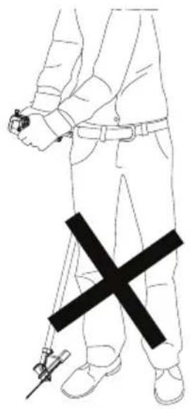
Installing and Removing the Shoulder Harness (Fig. L, M)
WARNING: The shoulder straps 38 should be slung over both shoulders 39 and not across the body. See Fig. M. The shoulder harness 21 will fit sizes XS–XXL.
A dual shoulder harness 21 is recommended for any tool with a total weight exceeding 6 kg (13 lbs.). (Total weight includes the tool, attachment, and battery.) Attach the dual shoulder harness to the tool as shown in Fig. L and adjust for proper balance and support.
- Grab the dual shoulder harness 21 and slide your arms through each one of the shoulder straps 38 ensuring each one hangs on your shoulders 39 as shown in Fig. M.
- Buckle the chest strap 40.
- Snap the shoulder strap latch 37 onto the strap mount 11 located on the pole 10, as shown in Fig. L.
- Tighten the shoulder straps 38 and chest strap 40 until they fit securely against your body and over your shoulders 39 to provide proper balance and support of the tool.
- To remove the dual shoulder harness 21, unbuckle the chest strap 40. Loosen the shoulder straps 38. Pull your arms through each one of the shoulder straps 38.
Shoulder Harness Quick Release (Fig. L, N-Q)
The dual shoulder harness 21 is equipped with a quick release mechanism 41. To quickly release the tool from the user without removing the dual shoulder harness, pull the quick release strap 42 as shown in Fig. N.
- To reattach the dual shoulder harness to the tool after pulling the quick release strap 42, remove the shoulder strap latch 37 as shown in Fig. L, from the strap mount 11.
- Slide the strap latch loop 43 onto the quick release mechanism 41 as shown in Fig. P.
- Slide the quick release fitting 44 through the quick release mechanism 41 as shown in Fig. Q.
- Attach the shoulder strap latch 37 to the strap mount 11 as shown in Fig. L.
OPERATION
WARNING: To reduce the risk of serious personal injury, turn unit off and remove the battery pack before making any adjustments or removing/installing attachments or accessories. An accidental start-up can cause injury.
Proper Hand Position (Fig. A, R)
WARNING: To reduce the risk of serious personal injury, ALWAYS use proper hand position as shown.
WARNING: To reduce the risk of serious personal injury, ALWAYS hold securely in anticipation of a sudden reaction.
WARNING: Hold the tool using only the two handle grips.
WARNING: Do not use the pole as a gripping surface.
Proper hand position requires one hand on the right hand grip 3 and one hand on the left hand grip 5 of the bike handle 4.
Switching On (Fig. C, S)
WARNING: Grip tool firmly when switching on.
AUTION: Always wear safety glasses and hearing protection. Wear a filter mask if the operation is dusty. Always wear gloves, long pants and substantial closed toe footwear. Keep long hair and loose clothing away from openings and moving parts.
- The speed control button/wake-up button 6 must be pressed before use to wake up the appliance.
NOTE: The appliance will enter sleep mode after sixty seconds of inactivity. The appliance can also be forced into sleep mode by pressing and holding the speed control button/wake-up button 6 for two seconds.
-
To turn the appliance on, push the lock-off lever 2 forward, and then squeeze the variable speed trigger switch 1 as shown in Fig. S.
-
To turn the appliance off, release the variable speed trigger switch and lock-off lever.
WARNING: Never attempt to lock the trigger switch in the on position.
Adjusting Motor Speed (Fig. C)
The DCMBC723 is equipped with a speed indicator 9. The speed indicator 9 will display the chosen speed. There are three speed setting LEDs, ECO mode 48, standard mode 49 and turbo mode 50. The speed indicator 9 helps you to optimize the appliance's performance and runtime needed for each job.
- The speed control button/wake-up button 6 must be pressed before use to wake up the appliance.
nOTE: The tool defaults to ECO mode 48.
- Press the speed control button/wake-up button 6, located on the appliance handle, until the desired speed LED is illuminated.
NOTE: Operate in ECO mode 48 or standard mode 49 for larger projects that require more runtime to complete.
- Choose turbo mode 50 as needed to cut through heavier growth and for applications that need higher RPM.
nOTE: Runtime will be reduced.
Speed Setting LED Colors
SPEED SPEED SETTING LED COLOR

Brushsaw Cutting (Fig. R, T–V)
WARNING: Keep all bystanders clear and away from the area you are cutting in at least two to three times the length of the tree being felled.
WARNING: Flying debris can cause serious injury. To reduce the risk that the brushesaw blade will crack or shatter, avoid all contact with stones, rocks or the ground. Keep the brushesaw blade parallel with the ground.
WARNING: Only use sharp brushesaw blades. Dull saw teeth may cause the brushesaw blade to crack or shatter.
Helpful Cutting Tips
With the DCMBC723 on, angle it and cut from right to left (anticlockwise direction) as shown in Fig. R.
Maintain a minimum distance of 610 mm (24") between the guard and your feet as shown in Fig. U.
WARNING: Keep the rotating blade roughly parallel with the ground (tilted no more than 30°). This brush saw is not an edger. DO NOT TILT the brush saw so that the blade is spinning near a right angle to the ground. Flying debris can cause serious injury as shown in Fig. V.
Brush saw blades can be used for clearing brush and cutting small diameter trees up to 40 mm (1.5"). Do not attempt cutting a tree with a larger diameter, use a chain saw instead. When a brush saw blade is used to cut down small trees, users should place the left side of the guard against the tree trunk before beginning to cut. This will keep the guard against the tree during the cutting operation and will reduce the risk of loss of control and possible kickback.
- The brush saw cuts best when passing the unit from the right to left. This will help reduce the possibility of the brush saw kicking back towards the operator.
- Before starting the cut, allow the brush saw blade to reach full speed. Do not force the brush saw blade into the tree or brush, allow the brush saw blade to do the cutting. Place the brush saw blade to the right of the tree, using the unshaded area of the brush saw blade, as shown below.

natural_image
Diagram of a mechanical or electrical component with a circular dial and a tree-like circular element, showing directional arrows (no text or symbols)- The risk of kickback is highest when cutting in the dark shaded area of the brushesaw blade, as shown below. To reduce the risk of kickback and personal injury, do not use this area of the brushesaw blade for cutting trees or shrubs. Special techniques using the lighter shaded areas of the blade to cut shrubs and trees should only be used by experienced operators with specialized training in the use and control of the brushesaw.

natural_image
Diagram of a circular mechanical or environmental symbol with arrows indicating direction, no text or labels present.MAINTENANCE
Your power tool has been designed to operate over a long period of time with a minimum of maintenance. Continuous satisfactory operation depends upon proper tool care and regular cleaning.
WARNING: To reduce the risk of serious personal injury, turn tool off and disconnect battery pack before making any adjustments or removing/installing attachments or accessories. An accidental start-up can cause injury. The charger and battery pack are not serviceable.
Please refer to the back page of this manual for service centre contact information, or visit www.2helpU.com.
Applying Grease (Fig. W)
The DCMBC723 needs to be greased after every 100 hours of use.
- Using a 5 mm hex wrench (not included), remove the grease port screw 45 and motor grease port screw 46.
- Apply a small amount (3-5 grams) of DEWALT 30301914 grease 47 into the ports as shown in Fig. W.
- Reinstall the port screws 45 and 46, using a 5 mm hex wrench (not supplied) to tighten the screws.
Cleaning
WARNING: Electrical shock and mechanical hazard. Remove the battery before cleaning.
WARNING: To ensure safe and efficient operation, always keep the electrical appliance and the ventilation slots clean of debris.
WARNING: Never use solvents or other harsh chemicals for cleaning the non-metallic parts of the tool. These chemicals may weaken the materials used in these parts. Use a cloth dampened only with water and mild soap. Never let any liquid get inside the tool; never immerse any part of the tool into a liquid. Ventilation slots can be cleaned using a dry, soft non-metallic brush and/or a suitable vacuum cleaner. Do not use water or any cleaning solutions. Wear approved eye protection and an approved dust mask.
Optional Accessories
WARNING: Since accessories, other than those offered by DEWALT, have not been tested with this product, use of such accessories with this tool could be hazardous. To reduce the risk of injury, only DEWALT-recommended accessories should be used with this product. Consult your dealer for further information on the appropriate accessories.
WARNING: To reduce the risk of serious personal injury, turn appliance off and remove battery before making any adjustments or removing/installing attachments or accessories.
WARNING: The use of any accessory not recommended by DEWALT for use with this appliance could be hazardous.
WARNING: Do not use any blades, or any accessory or attachment other than those recommended by DEWALT on this trimmer. Serious injury or product damage may result.
WARNING: Do not use any blades, or any accessory or attachment other than those recommended by DEWALT. Serious injury or product damage may result.
Replacing the Brushesaw Cutting Blade (Fig. A, K)
WARNING: To reduce the risk of serious personal injury, turn unit off and remove the battery pack before making any adjustments or removing/installing attachments or accessories. An accidental start-up can cause injury. When replacing the brushesaw blade 17, use 254 mm (10") diameter blades. Use DEWALT replacement blade model number DT20696. Other sizes may degrade performance or cause damage to the brushesaw.
Removing the Cutting Blade
WARNING: Use gloves and proper eye protection. Be careful of the sharp edges of the blade.
- Remove the battery.
- Using pliers (not supplied), remove the cotter pin 34 from the shaft 33.
- Align the spindle plate hole 32 with the notch 32 and insert the locking rod 14 or a screwdriver (not supplied) into the hole. Hold the locking rod 14 or a screwdriver in position.
- While holding the locking rod 14 or a screwdriver, remove the flange nut 35 by turning it clockwise with the blade wrench 15 or a 19 mm wrench (not supplied) as shown in Fig. K.
- Remove the blade spacer 36, brushesaw blade 17 and the spindle plate 30 as shown in Fig. K. Examine all pieces for damage and replace if necessary.
Installing the New Brushesaw Blade
-
Install the spindle plate 30 onto the shaft 33 ensuring the teeth of the spindle align with the slots of the spindle plate 30.
-
Install the brushesaw blade 17 onto the shoulder of the spindle plate 30 as shown in Fig. K.
- Align the spindle plate hole 31 and notch 32, insert the locking rod 14 or a screwdriver into the hole and hold the locking rod 14 or a screwdriver in position.
- Install the blade spacer 36 on the blade 17 so that the wide flat side faces the blade.
- Install the flange nut 35 with the flange against the blade spacer 36 and securely tighten with the blade wrench 15 or a 19 mm wrench (not supplied).
- Use the blade wrench 15 or a 19 mm wrench (not supplied) to tighten the flange nut 35 counterclockwise against the blade spacer 36 while holding the locking rod 14 or a screwdriver:
- If using a torque wrench and an 19 mm socket, tighten to: 325 - 335 in-lb, 27 - 28 ft.-lb, 37 - 38 Nm.
- Without a torque wrench, use the blade wrench15 or a 19 mm closed-end wrench or 19 mm socket and ratchet, turning the nut until the blade retainer is snug against the shaft bushing. Ensure that the blade is installed correctly, then rotate the nut an additional 1/4 to 1/2 turn counterclockwise.
- Remove the locking rod 14 or a screwdriver from the spindle plate hole and notch 32.
- Using pliers (not included), install the cotter pin 34 into the shaft 33.
Protecting the Environment


Products/batteries are recyclable, but if marked with the crossed-out bin, they must not be disposed of with normal household waste.
Run the batteries down completely and separate them, and separate any light sources from the product if possible. It is the user's responsibility to delete personal data from the product. Then take the waste to an official waste collection center or a participating retailer who will often accept it free of charge. Packaging should be discarded based on the marked material code. Operating and safety instructions should only be discarded once the applicable product is no longer in use. Please check with your local community/municipality for waste management guidance. For further information, visit www.2helpU.com and scan the above QR code.
SIERRA FORESTAL 54V
DCMBC723


natural_image
Diagram of a mechanical or fluidic system with a circular component and directional arrows, no text or symbols present.natural_image
Diagram of a circular mechanical or environmental component with directional arrows, no text or symbols present.MANTENIMIENTO
natural_image
Diagram of a mechanical or electrical component with a circular arrow indicating rotation, showing internal structure and directional arrows (no text or symbols)natural_image
Cross-sectional diagram of a mechanical or environmental component with no visible text or symbolsMAINTENANCE
natural_image
Diagram of a mechanical or electrical component with a circular dial and a tree-like circular element, showing directional arrows (no text or symbols)natural_image
Diagram of a circular mechanical or electrical component with directional arrows and a circular feature, enclosed in a circle (no text or symbols)MANUTENZIONE
WAARSCHUWING: Lees alle

Vice-President Engineering, PTE-Europe
BEWAAR ALLE WAARSCHUWINGEN EN INSTRUCTIES ALS TOEKOMSTIG REFERENTIEMATERIAAL
| Accu(kg) |
| DCB5461,08 |
| DCB5471,46 |
| DCB5481,46 |
| DCB5492,12 |
natural_image
Diagram of a mechanical or electrical component with a circular dial and directional arrows, no visible text or symbols.natural_image
Diagram of a circular mechanical or electrical component with directional arrows and a circular inset showing a gear-like structure (no text or symbols)ONDERHOUD
natural_image
Diagram of a mechanical or electrical component with a circular arrow indicating rotation, showing internal structure and directional arrows (no text or symbols)natural_image
Cross-sectional diagram of a mechanical or electrical component with no visible text or symbolsVEDLIKEHOLD
natural_image
Diagram of a mechanical or fluidic system with a circular component and directional arrows, no text or symbols present.natural_image
Cross-sectional diagram of a road with tree stumps and directional arrows, no text or symbols presentMANUTENÇÃO
natural_image
Diagram of a mechanical or fluidic system with a circular component and directional arrows, no text or symbols present.natural_image
Diagram of a circular mechanical or electrical component with directional arrows, no text or symbols present.KUNNOSSAPITO
Vice-President Engineering, PTE-Europe
natural_image
Diagram of a mechanical or electrical component with a circular arrow indicating rotation, showing internal structure and motion direction (no text or symbols)natural_image
Diagram of a circular mechanical or electrical component with directional arrows and a circular feature, enclosed in a circle (no text or symbols)UNDERHÅLL
| Batarya(kg) |
| DCB5461,08 |
| DCB5471,46 |
| DCB5481,46 |
| DCB5492,12 |
natural_image
Diagram of a mechanical or fluidic system with a circular component and directional arrows, no text or symbols present.natural_image
Cross-sectional diagram of a mechanical or electrical component with no visible text or symbolsBAKIM
natural_image
Diagram of a mechanical or electrical component with a circular dial and a gear-like structure, showing directional arrows (no text or symbols)natural_image
Cross-sectional diagram of a mechanical device with no visible text or symbolsΣΥΝΤΗΡΗΣΗ

- 54V SKOVRYDNINGSSAV
- DCMBC723
- VEDLIGEHOLDELSE
- WARTUNG
- EC-Declaration of Conformity Machinery Directive
- FORESTRY CLEARING SAW DCMBC723
- DT20695-QZ (Brush to String Conversion Kit) DT20904-QZ (String to Brush Conversion Kit)
- Definitions: Safety Guidelines
- GENERAL POWER TOOL SAFETY WARNINGS
- SAVE ALL WARNINGS AND INSTRUCTIONS FOR FUTURE REFERENCE
- 1) Work Area Safety
- 2) Electrical Safety
- 3) Personal Safety
- 4) Power Tool Use and Care
- 5) Battery Tool Use and Care
- 6) Service
- Grass Trimmer, Brush Cutter and Brush Saw Safety Warnings
- Blade Thrust Causes and Related Warnings
- Additional Safety Information
- Residual Risks
- SAVE THESE INSTRUCTIONS
- Battery Type
- Package Contents
- EnGLIsh
- Markings on Tool
- Date Code Position (Fig. B)
- Description (Fig. A)
- Intended Use
- ASSEMBLY AND ADJUSTMENTS
- Inserting and Removing the Battery Pack from the Tool (Fig. B)
- To Install the Battery Pack into the Tool Handle
- To Remove the Battery Pack from the Tool
- State of Charge Indicator (Fig. A, C)
- Overloaded Battery Warning (Fig. A, C)
- Overload LED (Fig. A, C)
- Mounting the Bike Handle (Fig. D-I)
- Folding the Bike Handle (Fig. F-I)
- Folding:
- Unfolding:
- Assembling the Guard (Fig. J)
- Installing the Brushsaw Blade (Fig. A, K)
- Installing and Removing the Shoulder Harness (Fig. L, M)
- Shoulder Harness Quick Release (Fig. L, N-Q)
- OPERATION
- Proper Hand Position (Fig. A, R)
- Switching On (Fig. C, S)
- Adjusting Motor Speed (Fig. C)
- Speed Setting LED Colors
- SPEED SPEED SETTING LED COLOR
- Brushsaw Cutting (Fig. R, T–V)
- Helpful Cutting Tips
- MAINTENANCE
- Applying Grease (Fig. W)
- Cleaning
- Optional Accessories
- Removing the Cutting Blade
- Installing the New Brushesaw Blade
- Protecting the Environment
- SIERRA FORESTAL 54V
- MANTENIMIENTO
- MANUTENZIONE
- BEWAAR ALLE WAARSCHUWINGEN EN INSTRUCTIES ALS TOEKOMSTIG REFERENTIEMATERIAAL
- ONDERHOUD
- VEDLIKEHOLD
- MANUTENÇÃO
- KUNNOSSAPITO
- UNDERHÅLL
- BAKIM
- ΣΥΝΤΗΡΗΣΗ
Brand : DEWALT
Model : DCMBC723
Category : Saw