
40-C1000X4 - Battery charger HUSQVARNA - Free user manual and instructions
Find the device manual for free 40-C1000X4 HUSQVARNA in PDF.

| Product type | Battery charger for original Husqvarna 36 V batteries |
| Brand | Husqvarna |
| Model | 40-C1000X4 |
| Number of battery slots | 4 |
| Maximum charging power (total) | 1 000 W |
| Maximum charging power (per battery) | 600 W |
| Charging type | Parallel |
| Input voltage | 100-240 V AC, 50-60 Hz |
| Output voltage | 36 V DC |
| Operating temperature | -10 °C to 40 °C |
| Battery charging temperature | 0 °C to 50 °C |
| Dimensions (approx.) | 45 x 30 x 25 cm |
| Weight (approx.) | 4.5 kg |
| LED indicators | Green, red, yellow indicators for each slot |
| Safety functions | Protection against short circuits, overheating, defective battery |
| Maintenance | Do not clean with water, check the cord regularly |
| Storage | In a dry, clean place protected from frost, between 5 °C and 25 °C |
| Battery compatibility | 40-B140X, 40-B220X, 40-B330X, BLi100, BLi200, BLi300 |
| Warranty | See standard Husqvarna terms |
| Certifications | Compliant with EU and UK directives |
Frequently Asked Questions - 40-C1000X4 HUSQVARNA
User questions about 40-C1000X4 HUSQVARNA
0 question about this device. Answer the ones you know or ask your own.
Ask a new question about this device
Download the instructions for your Battery charger in PDF format for free! Find your manual 40-C1000X4 - HUSQVARNA and take your electronic device back in hand. On this page are published all the documents necessary for the use of your device. 40-C1000X4 by HUSQVARNA.
USER MANUAL 40-C1000X4 HUSQVARNA
EN Operator's manual 2-6
Troubleshooting....5
Transportation, storage and disposal.... 6
Technical data....6
Introduction
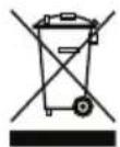
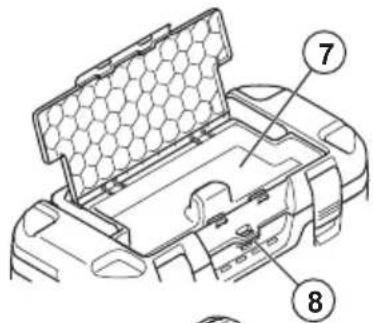
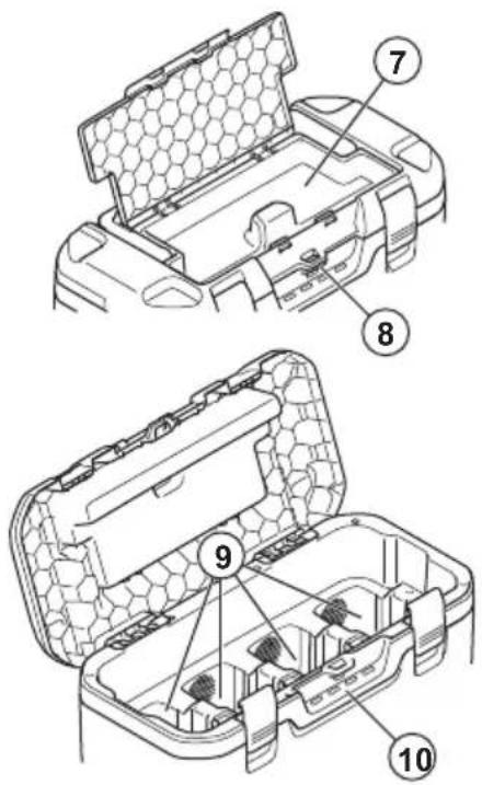
Product overview
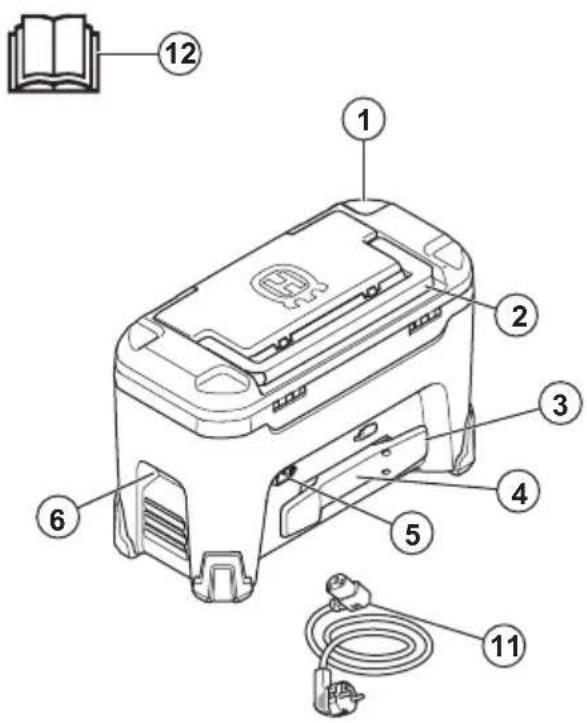

- Charger
- Top handle
- Power cord holder
- Storage for tracking device
- Power connector
- Side handles
- Storage section
- Padlock eye
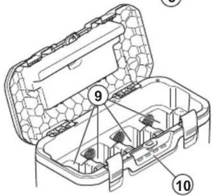
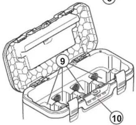
- Battery slots
- Charging indicators
- Power cord
- Operator's manual
Symbols on the product

Be careful and use the product correctly. This product can cause serious injury or death to the operator or others.

Read the operator's manual carefully and make sure that you understand the instructions before use.

The product agrees with the applicable EC directives.

This product conforms to applicable UK regulations.
The product or package of the product is not domestic waste. Recycle it at an applicable disposal location for electrical and electronic equipment.

Protection against splashing water.
Safety
SAFETY DEFINITIONS
Warnings, cautions and notes are used to point out specially important parts of the manual.

WARNING: Used if there is a risk of injury or death for the operator or bystanders if the instructions in the manual are not obeyed.

CAUTION: Used if there is a risk of damage to the product, other materials or the adjacent area if the instructions in the manual are not obeyed.
Note: Used to give more information that is necessary in a given situation.
Important safety instructions

WARNING: Read all safety warnings and all instructions. Failure to obey the warnings and
instructions may result in electrical shock, fire and/or serious injury.
- Only use the battery charger 40-C1000X4 to charge Husqvarna original 36 V batteries. Refer to Technical data on page 6 for specific batteries.
- Do not insert any object into the cooling slots of the charger.
- Do not try to disassemble or repair the battery charger.
- Do not use other power cords than the one supplied for your product.
- Regularly examine that the power cord is not damaged. Immediately disconnect the battery charger if the power cord is damaged.
- Do not lift the battery charger by the power cord. To disconnect the battery charger from a power outlet, pull out the power plug. Do not pull the power cord.
- Keep all cables and extension leads away from water, oil and sharp edges. Make sure
that the power cord is not caught between doors, fences or equivalent.
- Do not clean the battery or the battery charger with water.
- Keep the battery charger away from children.
- Do not use a defective or damaged battery charger or battery.
- Do not use the battery charger when there is a risk of lightning.
- Do not use the battery charger near flammable materials or materials that can cause corrosion. Pull out the power plug to the battery charger if there is smoke or fire.
- Do not put a cover on the battery charger during operation.
- This product produces an electromagnetic field during operation. This field may under some circumstances interfere with active or
passive medical implants. To reduce the risk of serious or fatal injury we recommend persons with medical implants to consult their physician and the medical implant manufacturer before operating this product.
- This appliance can be used by children aged from 8 years and above and persons with reduced physical, sensory or mental capabilities or lack of experience and knowledge if they have been given supervision or instruction concerning use of the appliance in a safe way and understand the hazards involved. Children shall not play with the appliance. Cleaning and user maintenance shall not be made by children without supervision.
- Make sure that the battery charger is put in the upright position on a flat, horizontal surface during charge.
Assembly
To assemble the product
- Connect the power plug to the product.
Operation
Operation
- Use the product only when the ambient temperature is between -10^ / 14^ and 40^ / 104^ .
- The battery does not charge if the battery temperature is more than 50^ / 122^ .
- The battery does not charge if the battery temperature is less than 0^ / 32^ .
• The batteries are charged in parallel.
- Keep the battery charger away from sunlight.
- Always keep the lid closed when it is possible.
Charge indicators
| Procedure Green | indicator | Red indicator | Yellow indicator | Description |
| Automatic function test X X X Indicators flash in sequence. | ||||
| State of charge 0–79% X Indicator flashes fast. | ||||
| State of charge 80--100% X Indicator flashes slowly. | ||||
| The temperature of the battery is out of range. | X | Continuous light. | ||
| The battery is fully charged. X Continuous light. | ||||
| There is an error in the battery compartment. | X | Continuous light. | ||
| Battery error X Indicator flashes. | ||||
| Battery charger error X 4 indicators come on at the same time. | ||||
To charge the battery
The battery charger charges the batteries in parallel. The maximum total charging power when you charge more than 1 battery is 1000 W. The maximum charging power when you charge 1 battery is 600 W.
The charge speed is set by the battery type, the state of charge and the number of batteries that charge.

CAUTION: Make sure that the battery, the battery charger and the terminals on the battery are clean and dry.
- Connect the battery charger to a power outlet.

CAUTION: Only connect the battery charger to a power outlet with the voltage and frequency specified on the rating plate.
- Connect the batteries to the battery charger. The charge indicators come on.
- Pull the power plug to disconnect the battery charger from the power outlet. Do not pull the power cord.
Troubleshooting
Battery charger
| Condition Possible faults Possible procedure | ||
| One or more indicators flash red. | Battery error. Disconnect the battery charger from the power outlet for a minimum of 2 minutes. Connect the battery charger to the power outlet. If the indicators continue to flash red, speak to your approved service agent. | |
| One or more indicators are red. | Defective charger. | Disconnect the battery charger from the power outlet for a minimum of 2 minutes. Connect the battery charger to the power outlet. If the indicators continue to be red, speak to your approved service agent. |
Transportation, storage and disposal
Transportation and storage
- Safely attach the product during transportation to prevent damage and accidents.
- Keep the product in a locked area to prevent access for children or persons that are not approved.
- Put the product in a dry, frost-free and clean space with correct temperature.
- Put the product in storage where the temperature is between 5^ (41 °F) and 25^ (77 °F). Keep the product away from sunlight.
- The chargers can be stored on top of each other.
Disposal
Husqvarna products are not domestic waste and must only be discarded as given in this manual.
- Obey the local disposal requirements and applicable regulations.
- Recycle the battery charger and package at an applicable disposal location.
- Speak to your local Husqvarna dealer for more information on how to recycle and discard the battery.
Technical data
Technical data
For technical data, refer to the rating plate of the battery charger.
| 40-B140X 40-B220X 40-B330X BLi100 BLi200 BLi300 | ||||||
| Capacity, Ah 4 | 6 | 9 | 2.5 | 5 | 9 | |
المحتويات


- Punjač
- Gornja ručka
- Držač kabela napajanja
- Pohrana uređaja za praćenje
- Priključak za napajanje
- Bočne ručke
- Odjeljak za pohranu
- Otvor za lokot
- Utori za bateriju
- Indikatori punjenja
- Kabel napajanja
- Korisnički priručnik
Simboli na proizvodu

Budite oprezni i pravilno upotrebljavajte ovaj proizvod. Ovaj proizvod može izazvati teške ozljede ili smrt rukovatelja ili drugih osoba.


- Punjač
- Gornja ručka
- Držač kabla za napajanje
- Čuvanje za uređaj za praćenje
- Konektor napajanja
- Bočne ručke
- Deo za čuvanje
- Otvor za katanac
- Otvori za bateriju
- Indikatori punjenja
- Kabl za napajanje
- Uputstvo za rukovaoca
Simboli na proizvodu

Budite pažljivi i koristite proizvod na pravilan način. Ovaj proizvod može prouzrokovati teške telesne povrede ili smrt rukovaoca i drugih osoba.


Original instructions
الأصلية الإرشادات
Оригинални инструкции
Původní pokyny

- Introduction
- Product overview
- Symbols on the product
- Safety
- SAFETY DEFINITIONS
- Important safety instructions
- Assembly
- To assemble the product
- Operation
- To charge the battery
- Troubleshooting
- Transportation, storage and disposal
- Transportation and storage
- Disposal
- Technical data
- المحتويات
- Simboli na proizvodu
Brand : HUSQVARNA
Model : 40-C1000X4
Category : Battery charger