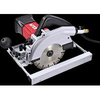
CS 60 WET - Sander Flex - Free user manual and instructions
Find the device manual for free CS 60 WET Flex in PDF.


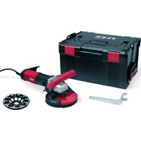
| Product type | Wet stone saw |
| Brand | Flex |
| Model | CS 60 WET |
| Mains voltage | 110 V / 50 Hz |
| Input power | 1400 W |
| Output power | 830 W |
| No-load speed | 6000 rpm |
| Max. disc diameter | 170 mm |
| Max. cutting height | 0–60 mm |
| Miter cut | 0–45° |
| Miter cutting depth | 5–44 mm |
| Weight (without cable) | 4.5 kg |
| Cable length | 4.0 m |
| Water connection | ½" (12.7 mm), max. pressure 6 bar |
| Protection class | II |
| Sound pressure level | 94 dB(A) |
| Sound power level | 105 dB(A) |
| Vibration emission (stone cutting) | ah = 4.2 m/s², K = 1.5 m/s² |
| Disc type | Diamond cutting discs |
| Intended use | Professional (industry and trade) |
| Protective hood | Yes, supplied |
| PRCD circuit breaker | Yes, integrated |
| Auxiliary handle | Yes |
| Parallel guide | Yes, adjustable |
| Guide rail | Optional (ref. 353.280) |
| Cleaning | Dry compressed air, no water |
Frequently Asked Questions - CS 60 WET Flex
User questions about CS 60 WET Flex
0 question about this device. Answer the ones you know or ask your own.
Ask a new question about this device
Download the instructions for your Sander in PDF format for free! Find your manual CS 60 WET - Flex and take your electronic device back in hand. On this page are published all the documents necessary for the use of your device. CS 60 WET by Flex.
USER MANUAL CS 60 WET Flex
natural_image
Illustration of a power tool with handle and blade assembly (no text or symbols)de Originalbetriebsanleitung 3
en Original operating instructions 16
fr Notice d'instructions d'origine 29
it Istruzioni per l'uso originali 42
es Instrucciones de funcionamiento originales ..... 55
pt Instruções de serviço originais ..... 68
nl Originele gebruiksaanwijzing 81
da Originale driftsvejledning 94
no Originale driftsanvisningen 107
sv Originalbruksanvisning 120
fi Alkuperäinen käyttöohjekirja 133
el Auθεντικές οδηγίες χειρισμού 146
pI Instrukcja oryginalna 160
hu Eredeti üzemeltetési útmutató ..... 174
cs Originální návod k obsluze 187
sk Originálny návod na obsluhu 200
et Originaalkasutusjuhend 213
It Originali naudojimo instrukcija 226
Iv Lietošanas pamācības oriģināls 239
ru Оригинальная инструкция по эксплуатации ..... 252
Inhalt
Verwendete Symbole 3
Symbole am Gerät 3
natural_image
Close-up of a fuel nozzle with a valve and connector (no text or symbols visible)natural_image
Mechanical assembly diagram showing a wheel and gear assembly with directional arrows indicating motion (no text or symbols)natural_image
Person using a power tool on a cutting board, no visible text or symbolsnatural_image
Person using a power tool on a cutting board, no visible text or symbolsnatural_image
Diagram showing two types of metal profiles with arrows indicating movement or assembly (no text or symbols present)natural_image
Diagram of a mechanical assembly with two parallel plates and a central rod, showing directional arrows (no text or symbols)natural_image
Illustration of a manual tool cutting through a saw blade, showing mechanical components and wiring (no text or symbols)natural_image
Illustration of a hand using a cutting tool to cut a metal sheet, with two inset views showing mechanical components (no text or symbols present)Wartung und Pflege

WARNUNG!
Peter Lameli
Technical Head
Klaus Peter Weinper Head of Quality Department (QD)
15.12.2020
Symbols used in this manual ..... 16
Symbols on the power tool 16
Important safety information ..... 16
Noise and vibration 19
Overview 20
Technical specifications ..... 21
Operating instructions ..... 22
Maintenance and care 27
Disposal information 27
C ∈ Declaration of Conformity ..... 28
UK CA Declaration of Conformity ..... 28
Exemption from liability 28
Symbols used in this manual

WARNING!
Denotes impending danger.
Non-observance of this warning may result in death or extremely severe injuries.

CAUTION!
Denotes a possibly dangerous situation.
Non-observance of this warning may result in slight injury or damage to property.

NOTE
Denotes application tips and important information.
Symbols on the power tool

Before switching on the power tool, read the operating manual!

Wear eye and ear protection!
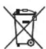
Disposal information for the old machine (see page 27)!
For your safety

WARNING!
Before using the power tool, please read and follow:
– these operating instructions,
- the "General safety instructions" on the handling of power tools in the enclosed booklet (leaflet-no.: 315.915),
– the currently valid site rules and the regulations for the prevention of accidents.
This power tool is state of the art and has been constructed in accordance with the acknowledged safety regulations.
Nevertheless, when in use, the power tool may be a danger to life and limb of the user or a third party, or the power tool or other property may be damaged.
The power tool may be operated only if it is
- as intended,
- in perfect working order.
Faults which impair safety must be repaired immediately.
Intended use
The stone separator CS 60 WET designed
– for commercial use in industry and trade,
– for separation work and for cutting grooves, employing a water supply, in artificial and natural stone, concrete, masonry,
– for use with diamond-tipped cutting-off wheels which FLEX offers for this power tool and which are authorised to run at a speed of at least 6200 r.p.m.
It is not permitted to use circular saw blades.
Safety instructions

WARNING!
Read all safety instructions and other instructions. Failure to observe the safety instructions and other instructions may result in an electric shock, fire and/or serious injuries. Keep all safety instructions and other instructions in a safe place for the future.
■ Always use the guard hood supplied with the electric power tool. The guard hood must be attached securely to the electric power tool and adjusted to ensure maximum safety, i.e. the operator is exposed to the smallest possible part of the insertion tool. Ensure that you and anybody in the vicinity remain outside the plane of the rotating insertion tool. The guard hood is intended to protect the operator from fragments and accidental contact with the insertion tool.
■ Use only diamond-tipped cutting-off wheels which were designed and recommended by the manufacturer especially for this electric power tool. Just because you can attach the accessory to your electric power tool does not guarantee safe use.
■ The permitted speed of the cutting-off wheel must be at least as high as the maximum speed indicated on the electric power tool. An accessory which rotates faster than permitted may shatter and fly off.
■ Cutting-off wheels may be used for the recommended applications only. For example: Never grind with the side area of a diamond-tipped cutting-off wheel. Diamond-tipped cutting-off wheels are designed for peripheral grinding. If a lateral force is applied to these tools, they may shatter.
■ Always use undamaged clamping flanges in the correct size and shape for the insertion tool you have selected. Suitable flanges support the insertion tools and therefore reduce the risk of a break.
■ Do not use worn cutting-off wheels from larger electric power tools. Insertion tools for larger electric power tools are not designed for the higher speeds of smaller electric power tools and may break.
■ Outer diameter and thickness of the insertion tool must correspond to the dimensions of the electric power tool. Incorrectly measured insertion tools cannot be adequately shielded or controlled.
■ The bores of the cutting-off wheels and clamping flanges must exactly match the grinding spindle of your electric power tool. Insertion tools, which do not fit exactly on the grinding spindle of the electric power tool, rotate unevenly, vibrate violently and may result in loss of control.
- Do not use any damaged insertion tools. Before use, always check the insertion tools for splinters and cracks. If the electric power tool or the insertion tool is dropped, check for damage or use an undamaged insertion tool. When you have checked and inserted the tool, ensure that you and anybody in the vicinity remain outside the plane of the rotating insertion tool and leave the power tool running for one minute at maximum speed. Damaged insertion tools usually break during this test time.
■ Wear personal protective equipment. Depending on the application, wear full face protection, eye protection or goggles. If appropriate, wear a dust mask, hearing protection, protective gloves and/or a special apron which protect you from small sanding and material particles. You should protect your eyes from foreign objects which are ejected for different applications. Dust and respirator masks must filter the dust which is generated by the power tool for the particular application. If you are exposed to loud noise for a prolonged period, you may suffer hearing loss.
■ Ensure that other persons are situated at a safe distance from the work area. Anyone who enters the work area must wear personal protective equipment. Fragments of the workpiece or broken insertion tools may fly off and cause injuries even outside the direct working area.
■ If the insertion tool is at risk of coming into contact with concealed power cables or the power cord itself, hold the power tool by the insulated grip surfaces only. Contact with a live cable may also cause metal parts of the appliance to become live and result in an electric shock.
- Keep the power cord away from rotating insertion tools. If you lose control of the appliance, the power cord could be severed or become caught and your hand or arm may strike the rotating insertion tool.
■ Never put down the electric power tool until the insertion tool has come to a standstill. The rotating insertion tool may come into contact with the support surface, possibly resulting in you losing control of the electric power tool.
■ Never leave the electric power tool running while you are carrying it. Your clothing may become caught by accidental contact with the rotating insertion tool which may then drill into your body.
■ Regularly clean the ventilation slots on your electric power tool. The motor fan draws dust into the housing; a large build-up of metal dust may cause electrical hazards.
■ Never use the electric power tool near combustible materials. Sparks may ignite these materials.
Recoil and appropriate safety instructions
Kickback is the sudden reaction to a pinched or snagged rotating insertion tool, such as a sanding disc, sanding pad, wire brush, etc. Pinching or snagging may cause a rotating insertion tool to stop abruptly. As a result, an uncontrolled electric power tool is accelerated against the direction of rotation of the insertion tool at the blocking point.
■ Hold the electric power tool firmly and position your body and arms to allow you to absorb kickback forces. If fitted, always use the auxiliary handle to ensure the best possible control over the recoil forces or reaction torques when acceleration occurs. The operator can control kickback and reaction forces by taking appropriate precautions.
- Keep your hands away from the rotating insertion tool. The insertion tool may kickback over your hand.
- Keep your body out of the area into which the electric power tool moves when a recoil occurs. Kickback propels the electric power tool in the direction opposite to the movement of the sanding disc at the point of pinching.
■ Work especially carefully near corners, sharp edges, etc. Prevent the insertion tool from recoiling off the workpiece and jamming. The rotating insertion tool has a tendency to snag on corners, sharp edges or if it bounces. This causes a loss of control or kickback.
■ Do not use a chain or toothed saw blade. Such insertion tools frequently cause a kick-back or the loss of control of the electric power tool.
■ Avoid blocking the cutting-off wheel or exerting too high contact pressure. Do not make excessively deep cuts. Overloading the cutting-off wheel increases its stress and the susceptibility to twisting or blocking and therefore the possibility of a kickback or the grinding tool breaking.
■ If the cutting-off wheel jams or you interrupt work for any other reason, switch the electric power tool off and hold it steady until the wheel has come to a standstill. Never attempt to pull the still rotating wheel out of the workpiece, otherwise a kickback may occur. Establish and eliminate the cause of the jam.
■ Do not switch the electric power tool on again while it is in the workpiece. First let the cutting-off wheel reach full speed before you carefully continue cutting. Otherwise the wheel may jam, jump out of the workpiece or cause a kickback if the electric power tool is in the workpiece when switched on.
■ Support plates or large workpieces to reduce the risk of a cutting-off wheel jamming and causing a kickback. Large workpieces may sag under their own weight. The workpiece must be supported on both sides of the wheel, namely near the cutting-off wheel and along the edge.
- Be particularly careful when making "pocket cuts" in existing walls or other secluded areas. When the cutting-off wheel is inserted, it may cause a kickback if it cuts into gas or water lines, electric cables or other objects.
Additional safety instructions
■ If the rubber hood (8, see Section "Overview") is damaged, replace immediately.
■ The mains voltage and the voltage specifications on the rating plate must correspond.
Noise and vibration
The noise and vibration values have been determined in accordance with EN 60745.
The A evaluated noise level of the power tool is typically:
– Sound pressure level: 94 dB(A);
– Sound power level: 105 dB(A);
- Uncertainty: K = 3 dB.
Total vibration value (when cutting natural stone):
- Emission value: a _h = 4.2 m/s ^2
– Uncertainty: K = 1.5 m/s

CAUTION!
The indicated measurements refer to new power tools. Daily use causes the noise and vibration values to change.

NOTE
The vibration emission level given in this information sheet has been measured in accordance with a standardised test given in EN 60745 and may be used to compare one tool with another. It may be used for a preliminary assessment of exposure. The declared vibration emission level represents the main applications of the tool. However if the tool is used for different applications, with different accessories or poorly maintained, the vibration emission may differ. This may significantly increase the exposure level over the total working period. For a precise estimation of the vibration load the times should also be considered during which the power tool is switched off or even running, but not actually in use. This may significantly decrease the exposure level over the total working period. Identify additional safety measures to protect the operator from the effects of vibration such as: maintain the tool and the accessories, keep the hands warm, organisation of work patterns.

CAUTION!
Wear ear protection at a sound pressure above 85 dB(A).
Overview
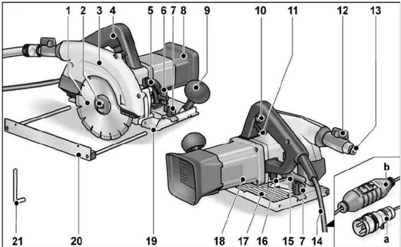
1 Diamond cutting disc
2 Spindle with threaded flange
3 Guard hood
4 Handle
5 Scale for mitre angle
6 Wing nut
for setting the mitre angle
7 W i n g s c r e w
for attachment of parallel stop
8 Rubber hood
9 Auxiliary handle
10 Switch interlock for switch
11 Switch
12 Shut-off valve
13 Coupling for water connection
14 4.0 m power cord with either
a plug in accordance with IEC60309-2 for connection to an isolating transformer or b PRCD safety switch
15 Clamping lever
for setting cutting depth
16 Spindle lock
17 Saw bench
18 Rating plate
19 Cut mark (0°/30°/45°)
20 Parallel stop
21 Hexagon-socket key
Technical specifications
| Machine type Stone separator | CS 60 WET | |
| Mains voltage V/Hz 110/50 | ||
| Protection class II/ | ☐ | |
| Power input W 1400 | ||
| Power output W 830 | ||
| Speed r.p.m. 6000 | ||
| Max. disc diameter mm 170 | ||
| Cutting depth mm 0–60 | ||
| Cutting depth with guide rail mm 0–54 | ||
| Mitre cut 0–45° | ||
| Cutting depth for mitre cut | mm | 5–44 |
| Cutting depth for mitre cut with guide rail | mm | 0–38 |
| Water connection | 12 " (for self-closing quick-action coupling), max. 6 bar | |
| Weight (without power cord) | kg | 4.5 |
Operating instructions

WARNING!
Before performing any work on the electric power tool, pull out the mains plug.
Before switching on the power tool Unpack power tool and accessories and check that no parts are missing or damaged.
Connection to the power supply – power tools with PRCD switch

WARNING!
This electric power tool may be operated with the supplied PRCD switch only. Before using the power tool, always check that the PRCD switch is functioning correctly. Before using the power tool, always check the PRCD switch
■ Insert the mains plug into the socket.
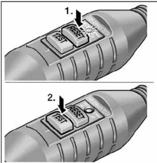
■ Press "RESET" button (1). The red indicator light must come on.
■ Press "TEST" button (2.). The PRCD switch must switch off and the indicator light go out.
■ When the "RESET" button is pressed again, it must be possible to switch on the machine.

WARNING!
If the PRCD switch repeatedly switches off when the machine is switched on or if the PRCD switch does not trip, immediately disconnect the machine from the power supply. Do not continue using the machine. Have the PRCD switch replaced by appro-priately qualified technicians or customer service only.
Connection to the isolating transformer – power tools with contour plug

WARNING!
In accordance with VDE 0100 hand-operated machines used for wet working must be operated via a suitable isolating transformer in accordance with EN 61558.

CAUTION!
Voltage specifications on the rating plate of the electric power tool must correspond with the output voltage of the isolating transformer used.
The electric power tool features a contour plug in accordance with IEC 60309-2 with an earth contact in the 12 o'clock position which allows the connection to an isolating transformer with corresponding socket.
The FLEX isolating transformer TT 2602/TT 2000 complies with the stated regulations.

WARNING!
Have the contour plug on the wet grinder replaced by appropriately qualified technicians or customer service only.
Water connection
i NOTE
If there is no connection to the water supply mains, it is recommended to use the mobile water pressure tank WD 10 (capacity 10 litres, 4 m pressure hose, order no. 251.622).
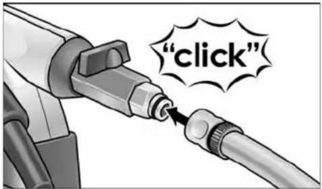
■ Attach 12 " water hose to standard self-locking quick coupling.
natural_image
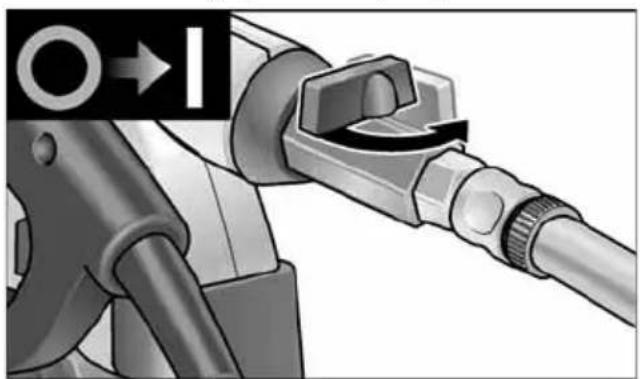
Close-up of a fuel nozzle with a valve mechanism (no text or symbols visible)■ Do not open shut-off valve until at the place of use and the cutting-off wheel is rotating.
i NOTE
When cutting, adjust the water supply as required. Re-adjust while cutting.
■ When removing the hose, ensure that no water runs into the machine.
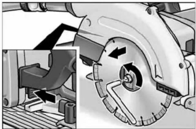
Attach or change diamond-tipped cutting-off wheel
■ Pull out the mains plug.
natural_image
Mechanical assembly diagram showing a brake shift mechanism with no visible text or symbols- Press and hold down the spindle lock. - Loosen clamping screw anti-clockwise using enclosed Allen key.
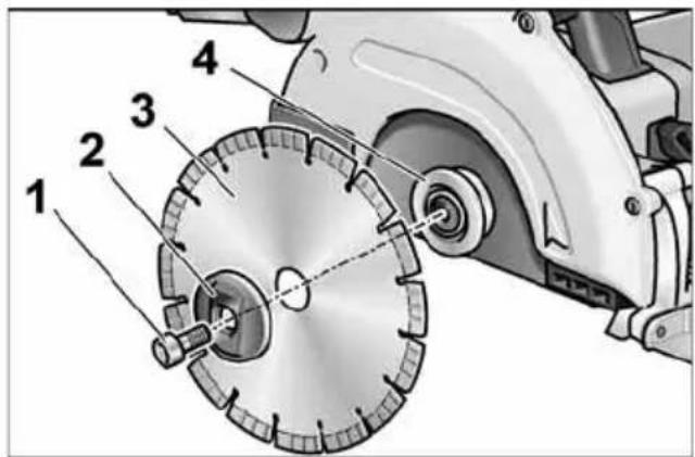
■ Unscrew clamping screw (1) and remove front clamping flange (2). Remove cutting-off wheel (3).
CAUTION!
- Note installation position of back (4) and front clamping flange (2).
- The cutting direction of the teeth (direction of arrow on the cutting-off wheel) and direction of rotation arrow on the housing must agree.
■ Insert cutting-off wheel in the correct position. Attach the front clamping flange (2) with the flange on the outside and manually tighten the locking screw (1) in a clockwise direction.
■ Press and hold down the spindle lock. Tighten clamping screw (1) with Allen key.
Switching on and off

CAUTION!
For reasons of safety the safety switch is not locked and must be held down during sawing.
Switching on
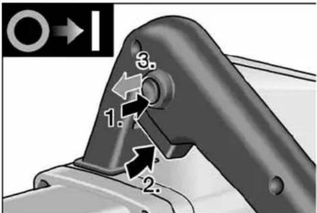
■ Press and hold down the switch interlock (1.).
■ Press and hold down the safety switch (2.).
■ Release switch interlock (3.).
Switching off
■ Release safety switch.
Switching on the power tool again following a power failure

WARNING!
Before switching on the power tool again following a power failure, always determine the cause of the power failure.
Do not switch on the electric power tool again until safe operation is possible.
Check function of the PRCD switch.
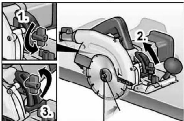
Setting the cutting depth

NOTE
To ensure optimum cutting results, the diamond-tipped cutting-off wheel may project a maximum 3 mm out of the workpiece.
■ Pull out the mains plug.
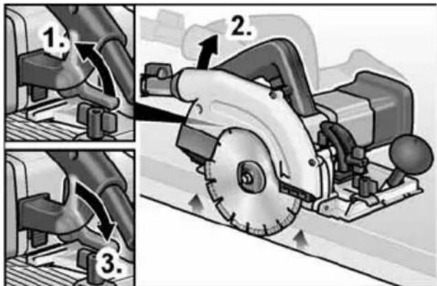
■ Release clamping lever for setting the cutting depth (1.).
■ Set required cutting depth (2.): Lift saw off saw bench = shallower cutting depth.
■ Tighten clamping lever (3.).
Setting the mitre angle

NOTE
In the case of mitre cuts, the cutting depth is reduced; if required re-adjust.
■ Pull out the mains plug.
■ Loosen clamping nut (1.).
■ Set required mitre angle with the aid of the scale (2.).
■ Tighten clamping nut (3.).
Parallel stop

WARNING!
Before performing any work on the electric power tool, pull out the mains plug.

NOTE
Before the saw can be placed in the supplied transportation case, the parallel stop must be removed.
To ensure optimum cutting results, the parallel stop must be attached when sawing.
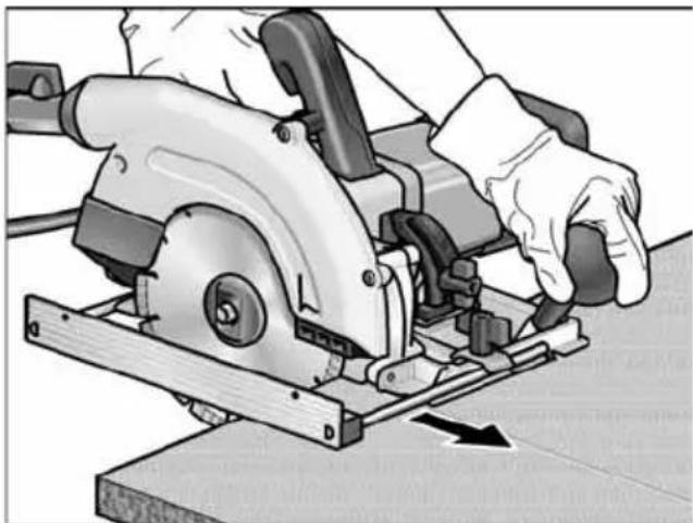
natural_image
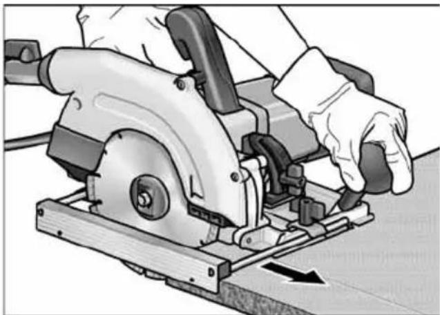
Person using a power tool on a cutting board, no visible text or symbolsStop edge upwards à Increases the contact surface of the saw bench.
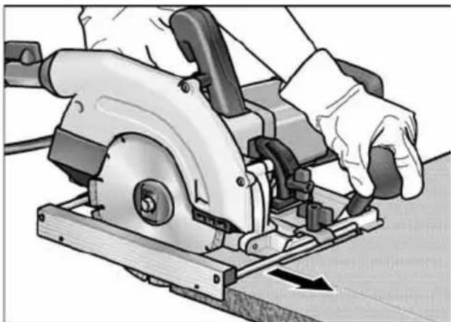
natural_image
Person using a power tool on a cutting board, no visible text or symbolsStop edge downwards à Facilitates cutting parallel to the workpiece edge.
Attaching parallel stop:
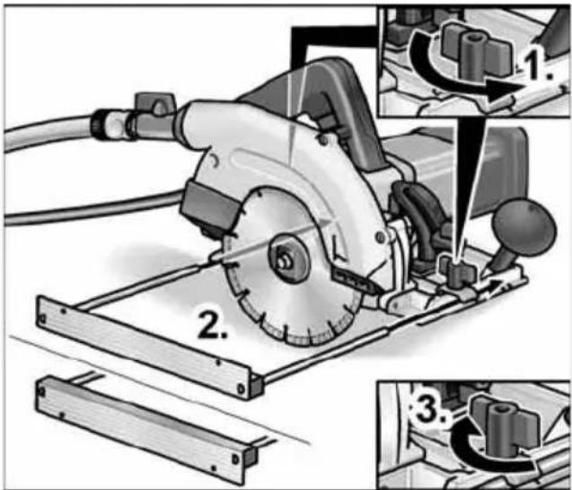
■ Loosen wing screws (1.).
■ Insert parallel stop (stop edge up or down) and set to required width (2.).
■ Retighten wing screws (3.).
Working with the power tool

CAUTION!
- When the power tool is switched off, the diamond-tipped cutting-off wheel continues running briefly.
- When the running cutting-off wheel touches the workpiece, a kickback may occur.

NOTE
Excessive feed lowers the performance of the power tool, impairs the cutting quality and reduces the service life of the diamond-tipped cutting-off wheel.
■ Set cutting depth to the required dimension.
■ If required, set the mitre angle.
■ Connect machine to the power supply.
■ Take hold of the handle with your right hand and the additional hand grip with your left hand.
■ Switch on saw and wait until the cutting-off wheel has reached the maximum speed.
■ Turn on water supply.
■ Place saw bench on the workpiece without bringing the diamond-tipped cutting-off wheel into contact with the workpiece.
■ Slowly feed the saw along the material.
■ Feed the saw evenly through the material.
■ If required, re-adjust the water supply.
■ After cutting:
- Switch off the saw. Cutting-off wheel continues running briefly!
- Turn off water supply.
■ At the end of work:
Thoroughly clean the electric power tool and accessories.
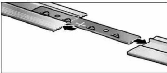
Guide rail
A guide rail (800 mm long) for the stone separator is available from any FLEX-customer service centre (order no. 353.280). To extend the guide length, 2 guide rails can be connected to each other. To do this, a connector is available from any FLEX customer service centre (order no. 353.272).
Fitting the connector:
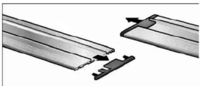
natural_image
Diagram showing two metal structural components with arrows indicating assembly or movement (no text or symbols present)■ Remove protective caps from the guide rails.
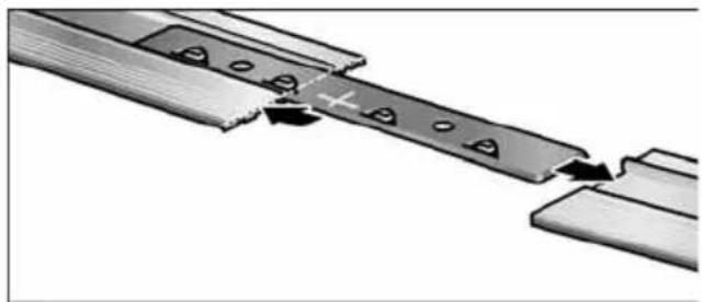
natural_image
Diagram of a mechanical assembly with two parallel plates and a central rod, showing directional arrows (no text or symbols)■ Push connector halfway along the guide rails.
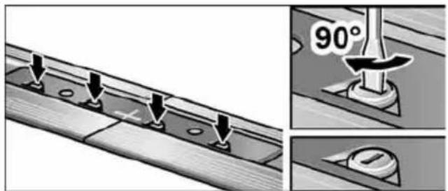
■ Clamp cams (4x).
"Sawing in" the guide rail:
i NOTE
Before using the guide rail for the first time, cut the anti-splinter shoe to the required width. It is recommended to use a new diamond-tipped cutting-off wheel.
■ Set the mitre angle to 0^ .
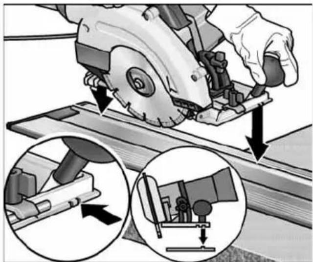
■ Set cutting depth to 15 mm (1.).
■ Place guide rail on a stable, level support ensuring that the anti-splinter shoe projects at the front.
■ Switch on saw.
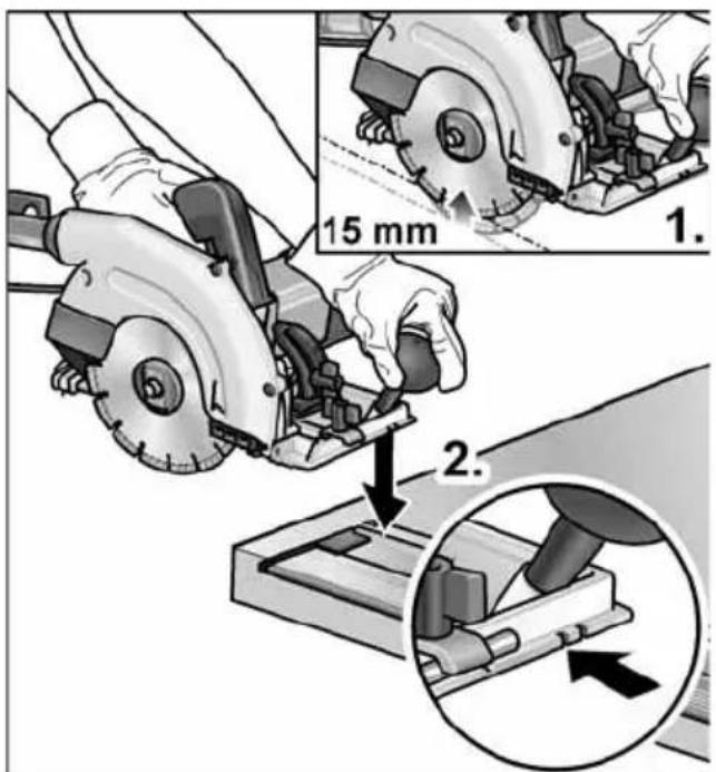
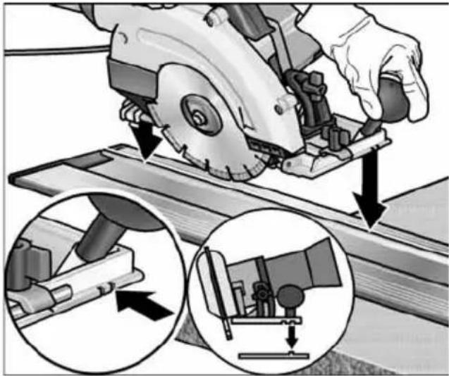
■ Place saw with the inner guide groove on the guide rail (2.).
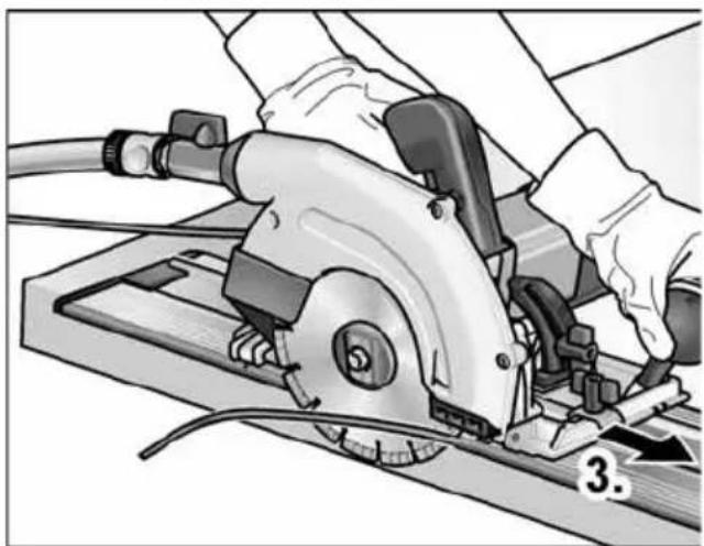
natural_image
Illustration of a manual cutting tool with a blade and handle, no text or symbols present■ Feed saw evenly in the direction of the cut as far as the end of the guide rail (3.).
Using the guide rail
i NOTE
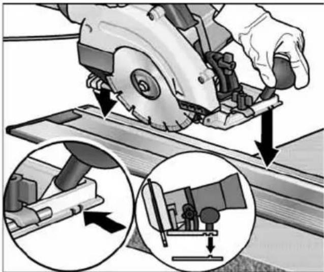
When placing the saw on the guide rail, always use the guide grooves.
Inner guide groove at mitre angle of 0^
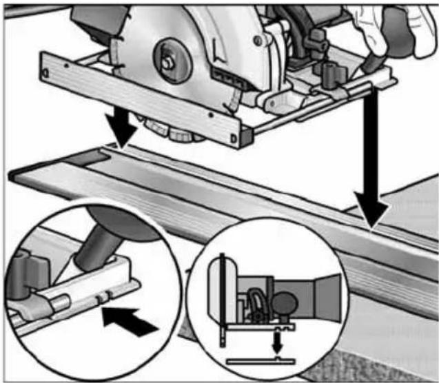
Outer guide groove at mitre angle set > 0°
natural_image
Illustration of a manual cutting machine with mechanical components and tool path, showing step-by-step assembly (no text or symbols)Maintenance and care
WARNING!
Before performing any work on the electric power tool, pull out the mains plug.
Cleaning the electric power tool
WARNING!
Do not use water or liquid detergents.
■ Regularly blow out the housing interior and motor with dry compressed air.
■ At the end of work immediately remove abrasion-water mixture to prevent it from drying and becoming encrusted.
■ When changing the diamond-tipped cutting-off wheel, clean the interior of the guard hood.
■ Also clean the guide rail, otherwise the saw will not be guided properly resulting in an inaccurate cut.
Repairs
Repairs may be carried out by an authorised customer service centre only.
i NOTE
During the warranty period do not loosen the screws on the motor housing.
Non-compliance will deem the guarantee obligations of the manufacturer null and void.
Spare parts and accessories
Other accessories, in particular insertion tools, can be found in the manufacturer's catalogues.
Exploded drawings and spare-part lists can be found on our homepage:
www.flex-tools.com
Disposal information
WARNING!
Render redundant power tools unusable by removing the power cord.

EU countries only
Do not throw electric power tools into the household waste!
In accordance with the European Directive 2012/19/EU on Waste Electrical and Electronic Equipment and transposition into national law used electric power tools must be collected separately and recycled in an environmentally friendly manner.
i NOTE
Please ask your dealer about disposal options!
CE Declaration of Conformity
We declare under our sole responsibility that the product described under “Technical specifications” conforms to the following standards or normative documents
EN 60745 in accordance with the regulations of the directives 2014/30/EU, 2006/42/EC, 2011/65/EU.
Responsible for technical documents:
Peter Lameli Technical Head
Klaus Peter Weinper Head of Quality Department (QD)
15.12.2020
Declaration of Conformity
We as the manufacturer: FLEX Elektro-werkzeuge GmbH,
Business address: Bahnhofstr. 15, 71711 Steinheim, Germany
declare under our sole responsibility, that the product(s) described under "Technical specifications" fulfills all the relevant provisions of The Supply of Machinery (Safety) Regulations S.I. 2008/1597 and also fulfills all the relevant provisions of the following UK Regulations:
Electromagnetic Compatibility Regulations S.I. 2016/1091, The Restriction of the Use of Certain Hazardous Substances in Electrical and Electronic Equipment Regulations S.I. 2012/3032 and are manufactured in accordance with the following designated Standards:
BS EN 60745-1:2010,
BS EN 60745-2-22:2011,
BS EN 55014-1:2017,
BS EN 55014-2:2015,
BS EN 61000-3-2:2014,
BS EN 61000-3-3:2013
Place of declaration: Steinheim, Germany.
Responsible person: Peter Lameli, Technical Director - FLEX-Elektrowerk-zeuge GmbH
Contact details for Great Britain: FLEX Power Tools Limited, Unit 8 Anglo Office Park, Lincoln Road, HP 12, 3RH Buckinghamshire, United Kingdom.
Peter Lameli Technical Head
Klaus Peter Weinper Head of Quality Department (QD)
19.05.2021
Exemption from liability
The manufacturer and his representative are not liable for any damage and lost profit due to interruption in business caused by the product or by an unusable product.
The manufacturer and his representative are not liable for any damage which was caused by improper use of the power tool or by use of the power tool with products from other manufacturers.
Table des matières
natural_image
Close-up of a fuel nozzle with a valve and connector (no text or symbols visible)natural_image
Mechanical assembly diagram showing a brake shift mechanism with no visible text or symbolsnatural_image
Person using a power tool on a cutting board, no visible text or symbolsnatural_image
Person using a power saw on a cutting board, no visible text or symbolsnatural_image
Diagram showing two metal structural components with arrows indicating movement or assembly (no text or symbols present)natural_image
Diagram of a mechanical assembly with two parallel plates and a central rod, showing alignment or disassembly (no text or symbols)natural_image
Illustration of a manual power tool cutting through a workpiece, showing mechanical components and wiring (no text or symbols)natural_image
Illustration of a hand using a cutting tool to cut a metal sheet, with two inset views showing mechanical components (no text or symbols present)Peter Lameli Technical Head
Klaus Peter Weinper Head of Quality Department (QD)
15.12.2020
natural_image
Close-up of a fuel pump nozzle with a valve and hose assembly (no visible text or symbols)natural_image
Mechanical assembly diagram showing a brake shift mechanism with no visible text or symbolsnatural_image
Person using a power tool on a cutting board, no visible text or symbolsnatural_image
Person using a power tool on a cutting board, no visible text or symbolsnatural_image
Diagram showing two metal profiles with arrows indicating movement or assembly (no text or symbols present)natural_image
Pure mechanical assembly diagram showing a sliding mechanism with no text or symbols■ Stringere l'eccentrico (4x).
natural_image
Illustration of a manual tool on a cutting board with a hand operating it (no text or symbols visible)natural_image
Illustration of a manual cutting machine with arrows indicating tool path and mechanical components (no text or symbols)Manutenzione e cura
PERICOLO!
Peter Lameli
Technical Head
Klaus Peter Weinper Head of Quality Department (QD)
15.12.2020
natural_image
Close-up of a fuel nozzle with a valve and connector (no text or symbols visible)natural_image
Mechanical assembly diagram showing a wheel and gear assembly with directional arrows indicating motion (no text or symbols)natural_image
Person using a power tool on a cutting board, no visible text or symbolsnatural_image
Person using a power tool on a cutting board, no visible text or symbolsnatural_image
Diagram showing two types of metal profiles with arrows indicating movement or assembly (no text or symbols present)natural_image
Diagram of a mechanical assembly with two parallel plates and a central rod, showing alignment or disassembly (no text or symbols)natural_image
Illustration of a manual tool on a cutting board with a hand operating it (no text or symbols visible)natural_image
Illustration of a hand using a cutting tool to cut a metal sheet, with two inset views showing mechanical components (no text or symbols present)
Peter Lameli
Technical Head
Klaus Peter Weinper Head of Quality Department (QD)
15.12.2020
natural_image
Close-up of a fuel nozzle with a valve and connector (no visible text or symbols)natural_image
Mechanical assembly diagram showing a brake caliper and wheel assembly with directional arrows (no text or labels)■ Desaparafusar o parafuso de aperto (1) e desmontar o flange de aperto (2) da frente. Desmontar o disco de corte (3).
AVISO!
natural_image
Person using a power tool on a cutting board, no visible text or symbolsAresta de batente para cima à Aumenta a superfície de apoio da mesa de serrar.
natural_image
Person using a power tool on a cutting board, no visible text or symbolsnatural_image
Diagram showing two metal profiles with arrows indicating movement or assembly (no text or symbols)natural_image
Pure mechanical assembly diagram showing two parallel plates with holes and a central shaft, no text or symbols present.natural_image
Illustration of a person using a power tool on a cutting board, no text or symbols presentRanhura de guia exterior com ângulo de meia esquadria de >0^ regulado
natural_image
Illustration of a hand using a saw to cut metal components, with two inset views showing mechanical assembly (no text or symbols)EN 60745 de acordo com as determinações das directivas 2014/30/UE, 2006/42/CE, 2011/65/UE.
Peter Lameli
Technical Head
Klaus Peter Weinper Head of Quality Department (QD)
15.12.2020
natural_image
Close-up of a fuel nozzle with a valve mechanism (no text or symbols visible)natural_image
Mechanical assembly diagram showing a brake shift mechanism with no visible text or symbolsnatural_image
Person using a power saw on a cutting board, no visible text or symbolsnatural_image
Person using a power tool on a cutting board (no text or symbols visible)natural_image
Diagram showing two metal structural components with arrows indicating assembly or movement (no text or symbols present)natural_image
Diagram of a mechanical assembly with metal components and directional arrows indicating motion (no text or symbols)■ Excenter spannen (4x).
natural_image
Illustration of a manual power saw cutting through a workpiece, showing tool path and component details (no text or symbols)natural_image
Illustration of a hand using a cutting tool to cut a metal sheet, with two inset views showing mechanical components (no text or symbols present)
Peter Lameli
Technical Head
Klaus Peter Weinper Head of Quality Department (QD)
15.12.2020
natural_image
Close-up of a fuel nozzle connecting a pipe with a valve, showing mechanical components and a directional arrow (no text or symbols)natural_image
Mechanical assembly diagram showing a brake shift mechanism with no visible text or symbolsnatural_image
Person using a power tool on a cutting board, no visible text or symbolsnatural_image
Person using a power saw machine to cut metal components (no text or symbols visible)natural_image
Diagram showing two types of metal profiles with arrows indicating movement or assembly (no text or symbols present)natural_image
Diagram of a mechanical assembly with two parallel plates and a central rod, showing directional arrows (no text or symbols)natural_image
Illustration of a manual power tool cutting through a workbench, with no visible text or symbolsUdvendig føringsnot med indstillet geringsvinkel > 0°
natural_image
Illustration of a manual cutting machine with a close-up inset showing the process (no text or symbols)natural_image
Close-up of a fuel nozzle with a valve and adjustment knob (no text or symbols visible)natural_image
Mechanical assembly diagram showing a brake caliper and wheel assembly with directional arrows (no text or labels)natural_image
Person using a power tool on a cutting board, no visible text or symbolsnatural_image
Person using a power tool on a cutting board, no visible text or symbolsnatural_image
Diagram showing two types of metal brackets with arrows indicating process or assembly (no text or symbols)natural_image
Diagram of a mechanical assembly with two parallel plates and a central shaft, showing directional arrows (no text or symbols)natural_image
Illustration of a manual tool on a cutting board with a hand operating it (no text or symbols visible)■ Skyv sagen framover jevnt i snittretningen inntil enden på føringsskinnen (3.).
natural_image
Illustration of a hand using a cutting tool to cut a metal sheet, with two inset views showing mechanical components (no text or symbols present)
Peter Lameli
Technical Head
Klaus Peter Weinper Head of Quality Department (QD)
15.12.2020
natural_image
Close-up of a fuel nozzle with a valve and hose assembly (no visible text or symbols)natural_image
Mechanical assembly diagram showing a brake shift mechanism with no visible text or symbolsnatural_image
Person using a power tool on a cutting board, no visible text or symbolsnatural_image
Person using a power tool on a cutting board, no visible text or symbolsnatural_image
Diagram showing two types of metal brackets with arrows indicating movement or assembly (no text or symbols present)natural_image
Diagram of a mechanical assembly with two parallel plates and a central rod, showing alignment or cutting process (no text or symbols)■ Dra åt. excentern (4x).
natural_image
Illustration of a manual power tool cutting through a workpiece, with no visible text or symbolsnatural_image
Illustration of a manual cutting machine with a close-up inset showing the mechanism (no text or symbols present)Underhåll
WARNING!
natural_image
Close-up of a fuel nozzle with a valve mechanism (no text or symbols visible)natural_image
Mechanical assembly diagram showing a brake caliper and wheel assembly with directional arrows (no text or labels)natural_image
Person using a power tool on a cutting board, no visible text or symbolsnatural_image
Person using a power tool on a cutting board, no visible text or symbolsnatural_image
Diagram showing two metal structural components with arrows indicating movement or assembly (no text or symbols present)natural_image
Diagram of a mechanical assembly with two parts and a central component, showing alignment or disassembly (no text or symbols)natural_image
Illustration of a manual tool on a cutting board with a hand operating it (no text or symbols visible)natural_image
Illustration of a hand using a cutting tool to cut a metal sheet, with two inset views showing mechanical assembly (no text or symbols)Huolto ja hoito
VAROITUS!

Peter Lameli
Technical Head
Klaus Peter Weinper Head of Quality Department (QD)
15.12.2020
natural_image
Close-up of a fuel nozzle with a valve and connector (no visible text or symbols)natural_image
Mechanical assembly diagram showing a brake shift mechanism with no visible text or symbolsnatural_image
Person using a power tool on a cutting board, no visible text or symbolsnatural_image
Person using a power tool on a cutting board, no visible text or symbolsnatural_image
Diagram showing two metal structural components with arrows indicating assembly or movement (no text or symbols present)natural_image
Diagram of a mechanical assembly with arrows indicating motion or force, showing components on a surface (no text or symbols)natural_image
Illustration of a manual tool cutting through a saw blade, showing mechanical components and wiring (no text or symbols)natural_image
Illustration of a manual cutting machine with hands operating it, showing step-by-step assembly and disassembly (no text or symbols)
Peter Lameli
Technical Head
Klaus Peter Weinper Head of Quality Department (QD)
15.12.2020
natural_image
Close-up of a fuel nozzle with a valve and connector (no visible text or symbols)natural_image
Mechanical assembly diagram showing a brake caliper and wheel assembly with directional arrows (no text or labels)natural_image
Person using a power tool on a cutting board, no visible text or symbolsnatural_image
Person using a power saw on a cutting board, no visible text or symbolsnatural_image
Diagram showing two metal structural components with arrows indicating assembly or movement (no text or symbols present)natural_image
Diagram of a mechanical assembly with two parallel plates and a central rod, showing alignment or cutting process (no text or symbols)natural_image
Illustration of a manual tool on a cutting board with a hand operating it (no text or symbols visible)natural_image
Illustration of a hand using a cutting tool to cut a wooden plank, with two inset diagrams showing mechanical components (no text or symbols present)
Peter Lameli
Technical Head
Klaus Peter Weinper Head of Quality Department (QD)
15.12.2020
natural_image
Close-up of a fuel nozzle with a valve and connector (no text or symbols visible)natural_image
Mechanical assembly diagram showing a brake shift mechanism with no visible text or symbolsnatural_image
Person using a power tool on a cutting board, no visible text or symbolsnatural_image
Person using a power tool on a cutting board, no visible text or symbolsnatural_image
Diagram showing two types of metal brackets with arrows indicating process or assembly (no text or symbols)natural_image
Pure mechanical assembly diagram showing a sliding mechanism with no text or symbolsnatural_image
Mechanical assembly diagram showing a tool on a cutting board with no visible text or symbolsnatural_image
Illustration of a hand using a cutting tool to cut a metal sheet, with two inset views showing mechanical components (no text or symbols present)Peter Lameli Technical Head
Klaus Peter Weinper Head of Quality Department (QD)
15.12.2020
natural_image
Close-up of a fuel nozzle with a rotary switch and connector (no text or symbols visible)natural_image
Mechanical assembly diagram showing a brake shift mechanism with no visible text or symbolsnatural_image
Person using a power tool on a cutting board, no visible text or symbolsnatural_image
Person using a power tool on a cutting board, no visible text or symbolsnatural_image
Diagram showing two metal structural components with arrows indicating assembly or movement (no text or symbols present)natural_image
Diagram of a mechanical assembly with two parallel plates and a central rod, showing alignment or disassembly (no text or symbols)natural_image
Illustration of a manual tool on a cutting board with a hand operating it (no text or symbols visible)natural_image
Mechanical assembly diagram showing a cutting tool and mechanical components with arrows indicating motion (no text or symbols present)Údržba a ošetřování
VAROVÁNÍ!
Peter Lameli Technical Head
Klaus Peter Weinper Head of Quality Department (QD)
15.12.2020
natural_image
Close-up of a fuel nozzle with a valve and connector (no visible text or symbols)natural_image
Mechanical assembly diagram showing a brake shift mechanism and internal components (no text or labels)■ Uvol'nite upínaciu páku nastavenia híbky rezu (1.).
■ Nastavenie potrebnej híbky rezu (2.): Zdvihnutie píly od stola píly = malá híbka rezu.
■ Upínaciu páku pevne utiahnite (3.).
natural_image
Person using a power tool on a cutting board, no visible text or symbolsnatural_image
Person using a power saw on a cutting board, no visible text or symbols■ Povol'te krídlové skrutky (1.).
■ Zasuňte paralelný doraz (hrana dorazu smerem nahor alebo nadol) a nastavte ho na požadovanú šírku (2.).
■ Krídlové skrutky znova pevne utiahnite (3.).
natural_image
Diagram showing two types of metal profiles with arrows indicating movement or assembly (no text or symbols present)natural_image
Diagram of a mechanical assembly with two parallel plates and a central rod, showing directional arrows (no text or symbols)■ Upnite excentre (4x).
„Vyrezanie“ vodiacej lišty:
i UPOZORNENIE
natural_image
Mechanical assembly diagram showing a tool on a cutting board with no visible text or symbolsnatural_image
Illustration of a hand using a cutting tool to cut a metal sheet, with two inset views showing mechanical components (no text or symbols present)Peter Lameli Technical Head
Klaus Peter Weinper Head of Quality Department (QD)
15.12.2020
natural_image
Close-up of a fuel nozzle with a valve and connector (no visible text or symbols)natural_image
Mechanical assembly diagram showing a brake shift mechanism with no visible text or symbols■ Keerata kinnitusmutter lahti (1.).
■ Seadistad skaala abil vajalik kaldnurk (2.).
■ Keerata kinnitusmutter kinni (3.).
Paralleelraam

HOIATUS!
natural_image
Person using a power saw on a cutting board, no visible text or symbolsnatural_image
Person using a power tool on a cutting board (no text or symbols visible)natural_image
Diagram showing two types of metal brackets with arrows indicating movement or assembly (no text or symbols present)natural_image
Diagram of a mechanical assembly with two parallel plates and a central rod, showing directional arrows indicating movement (no text or symbols)natural_image
Illustration of a manual power tool cutting through a workpiece, showing mechanical components and wiring (no text or symbols)natural_image
Illustration of a manual cutting machine with toolpath and mechanical components, showing progressive assembly (no text or symbols)natural_image
Close-up of a fuel nozzle with a valve and connector (no visible text or symbols)natural_image
Mechanical assembly diagram showing a brake shift mechanism with no visible text or symbolsnatural_image
Person using a power tool on a cutting board, no visible text or symbolsnatural_image
Person using a power tool on a cutting board, no visible text or symbolsnatural_image
Diagram showing two types of metal brackets with arrows indicating movement or assembly (no text or symbols present)■ Nuo kreipiamuju nuimkite apsauginius dangtelius.
natural_image
Pure mechanical assembly diagram showing two parallel plates with holes and a central shaft, no text or symbols present.natural_image
Close-up of hands operating a power saw on a cutting board, no visible text or symbols■ Pjūkla tolygiai stumkite pjovimo kryptimi iki kreipiamosios galo (3.).
natural_image
Illustration of a manual cutting machine with mechanical components, showing step-by-step assembly and close-up insets (no text or symbols)Klaus Peter Weinper
Head of Quality
Department (QD)
15.12.2020
natural_image
Close-up of a fuel nozzle with a valve mechanism (no text or symbols visible)natural_image
Mechanical assembly diagram showing a brake shift mechanism with no visible text or symbolsnatural_image
Person using a power saw on a cutting board, no visible text or symbolsnatural_image
Person using a power tool on a cutting board (no text or symbols visible)Attura mala uz leju à atvieglo griezumus paralēli sagataves malai.
natural_image
Diagram showing two metal structural components with arrows indicating assembly or movement (no text or symbols present)natural_image
Diagram of a mechanical assembly with two parallel plates and a central rod, showing alignment or disassembly (no text or symbols)■ Savelciet ekscebru (4x).
Vadstiena „iezāiēšana“:
i NORĀDĪJUMS
natural_image
Illustration of a manual tool on a cutting board with a hand operating it (no text or symbols visible)natural_image
Illustration of a hand using a saw blade to cut a wooden plank, with two inset views showing mechanical components (no text or symbols present)natural_image
Close-up of a fuel nozzle with a valve and connector (no visible text or symbols)natural_image
Mechanical assembly diagram showing a brake caliper and wheel assembly with directional arrows (no text or labels)natural_image
Person using a power tool on a cutting board, no visible text or symbolsnatural_image
Person using a power saw on a cutting board, no visible text or symbolsnatural_image
Diagram showing two types of metal brackets with arrows indicating movement or assembly (no text or symbols present)natural_image
Diagram of a mechanical assembly with two parallel plates and a central rod, showing alignment or dissection (no text or symbols)natural_image
Illustration of a manual tool on a cutting board with a power shaver (no text or symbols visible)natural_image
Illustration of a manual cutting machine with hands operating it, showing step-by-step assembly and disassembly (no text or symbols)
Peter Lameli
Technical Head
Klaus Peter Weinper Head of Quality Department (QD)
15.12.2020



- Inhalt
- Wartung und Pflege
- WARNUNG!
- Symbols used in this manual
- WARNING!
- CAUTION!
- NOTE
- Symbols on the power tool
- For your safety
- Intended use
- Safety instructions
- Recoil and appropriate safety instructions
- Additional safety instructions
- Noise and vibration
- Overview
- Operating instructions
- Water connection
- i NOTE
- Attach or change diamond-tipped cutting-off wheel
- Switching on and off
- Switching off
- Switching on the power tool again following a power failure
- Setting the cutting depth
- Setting the mitre angle
- Parallel stop
- Working with the power tool
- Guide rail
- "Sawing in" the guide rail:
- Using the guide rail
- Maintenance and care
- Cleaning the electric power tool
- Repairs
- Spare parts and accessories
- Disposal information
- CE Declaration of Conformity
- Declaration of Conformity
- Exemption from liability
- Table des matières
- Manutenzione e cura
- AVISO!
- Underhåll
- Huolto ja hoito
- VAROITUS!
- Údržba a ošetřování
- VAROVÁNÍ!
- „Vyrezanie“ vodiacej lišty:
- i UPOZORNENIE
- Paralleelraam
- HOIATUS!
- Vadstiena „iezāiēšana“:
- i NORĀDĪJUMS
Brand : Flex
Model : CS 60 WET
Category : Sander