
PI8022 - Cooker DOMETIC - Free user manual and instructions
Find the device manual for free PI8022 DOMETIC in PDF.
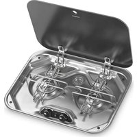


| Product type | Gas hob for caravan and motorhome |
| Brand | DOMETIC |
| Model | PI8022 |
| Number of burners | 2 |
| Burner type | Gas burners with integrated electric ignition (12 V) |
| Recommended pan diameter | Burner A and B: 9 to 15 cm |
| Nominal power per burner | Burner A: 1.18 kW; Burner B: 0.69 kW (indicative values) |
| Gas supply | Propane (G31) or butane (G30) – pressure 30 mbar or 37 mbar depending on country |
| Electrical supply | 12 V (direct current) – fuse 1 A required |
| Worktop material | Safety glass (lid) |
| Safety – Automatic shut-off | Flame monitoring: gas cut-off after about 20 seconds if flame goes out |
| Safety – Using the lid | Never close the glass lid when burners are lit (risk of breakage) |
| Installation type | Built-in into a caravan or motorhome worktop |
| Required ventilation | Opening of at least 150 cm² in the installation room during operation |
| Recommended cleaning | Standard cleaning products, excluding steam cleaners and sharp objects |
| Warranty | Legal warranty – contact the dealer or DOMETIC after-sales service |
| Certifications | CE |
Frequently Asked Questions - PI8022 DOMETIC
User questions about PI8022 DOMETIC
0 question about this device. Answer the ones you know or ask your own.
Ask a new question about this device
Download the instructions for your Cooker in PDF format for free! Find your manual PI8022 - DOMETIC and take your electronic device back in hand. On this page are published all the documents necessary for the use of your device. PI8022 by DOMETIC.
USER MANUAL PI8022 DOMETIC
Hob and cooking hobs and combinations
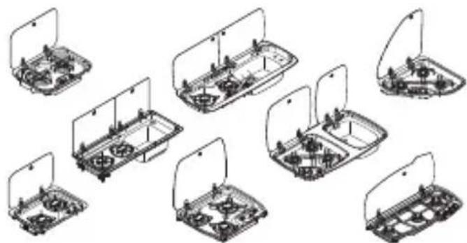
CE99-DF (HBG3445), CE99-ZF (HBG2335), KSK2007R, MO7103, MO7123, MO9222L (HSG2370L), MO9222R (HSG2370R), MO9722L, MO9722R, PI8002, PI8022, PI8023, PI9003, PI9023
EN
Cooktops and combinations
Installation and Operating Manual . 20
DE
Cooktops and combinations
Installation and Operating Manual 136
PL
© 2023 Dometic Group. The visual appearance of the contents of this manual is protected by copyright and design law. The underlying technical design and the products contained herein may be protected by design, patent or be patent pending. The trademarks mentioned in this manual belong to Dometic Sweden AB. All rights are reserved.
NOTICE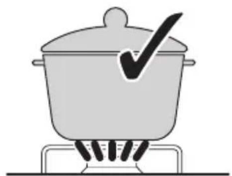
1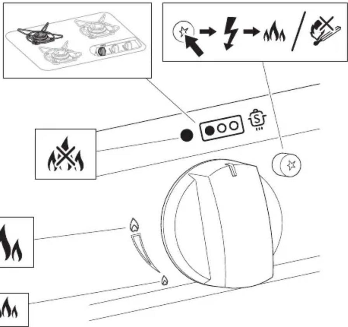
4 PI80x3 (HBG3440)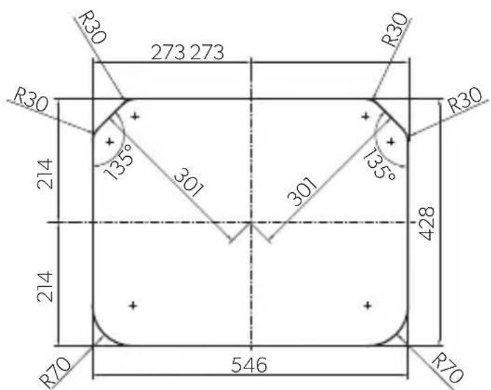
5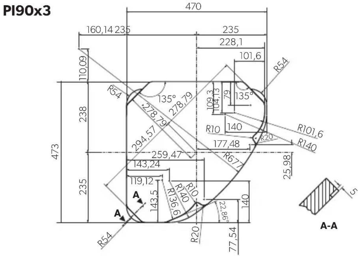


CE99-ZF (HBG2335)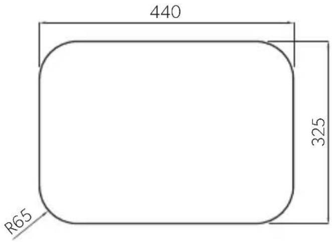

CE99-DF (HBG3445)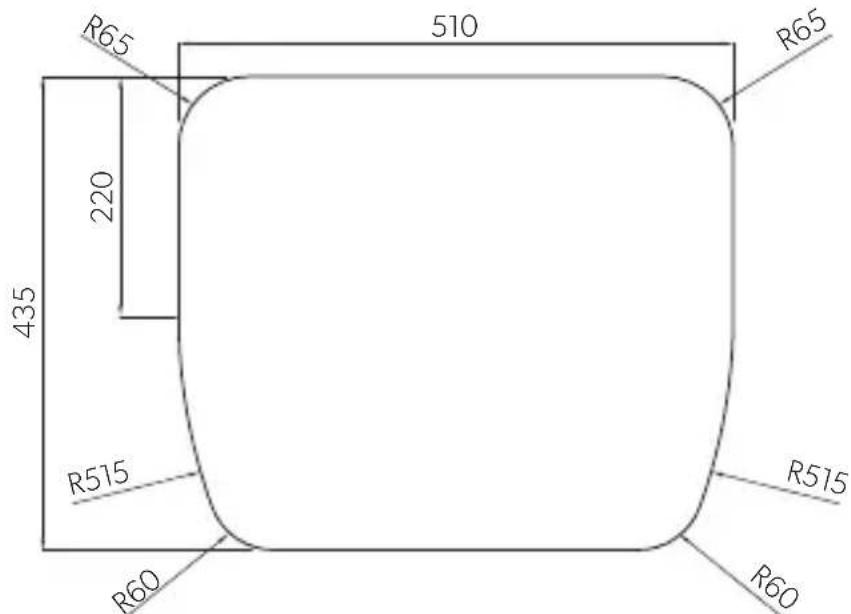
11 KSK2007R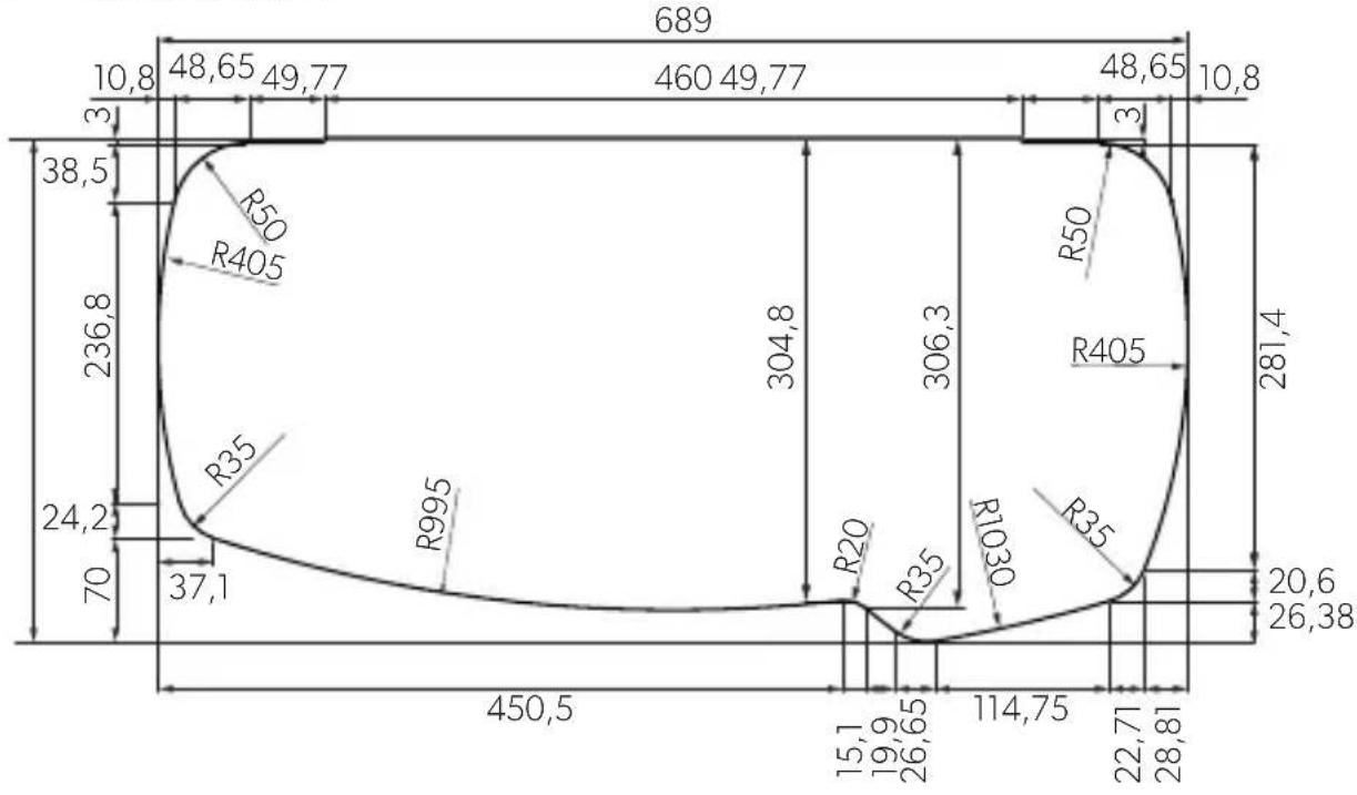
12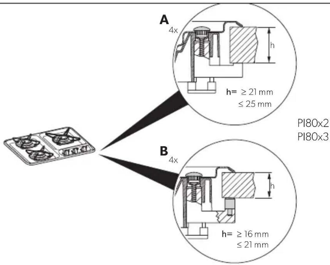
14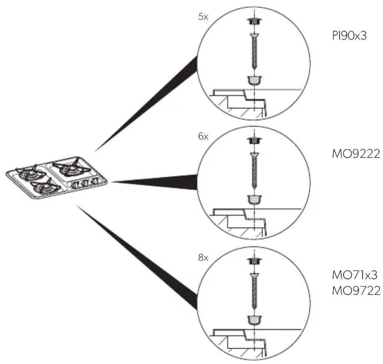
15 A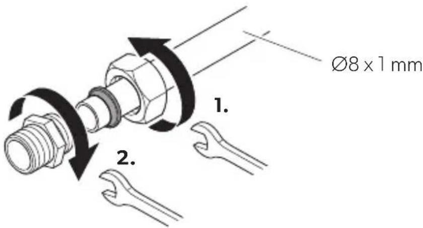
B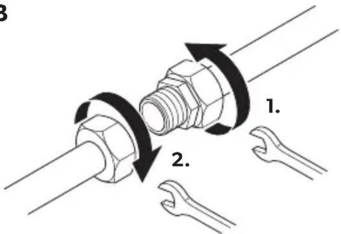
16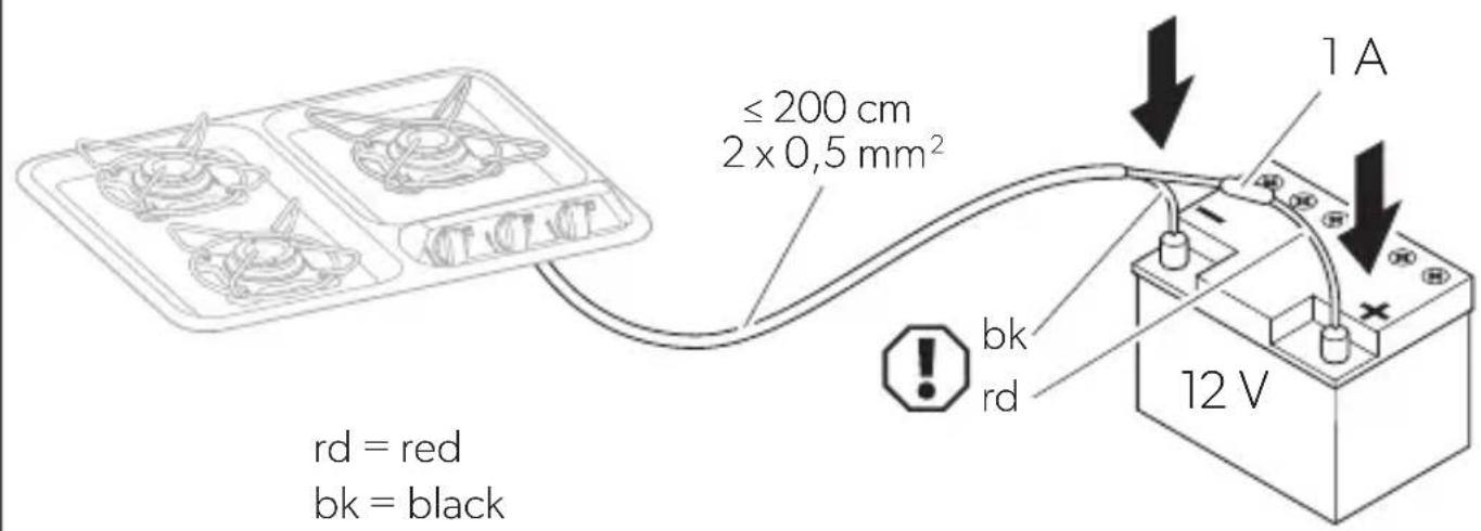
17 PI80X2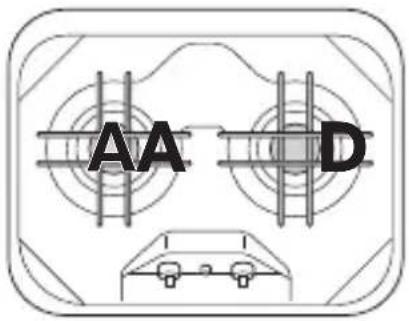
MO9222R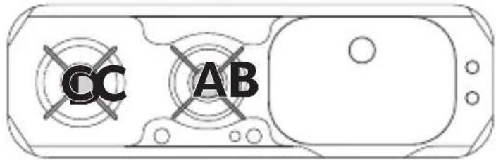
MO9222L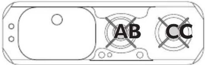
PI80X3 (HBG3440)
MO9722R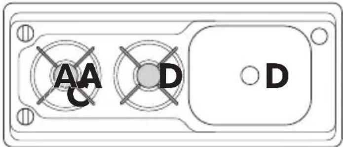
PI90X3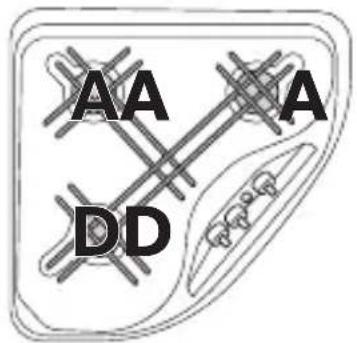
MO9722L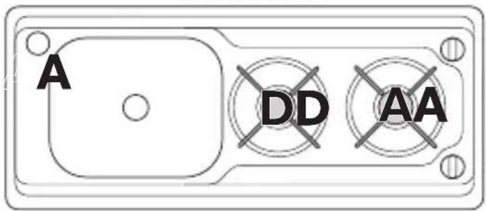
MO71X3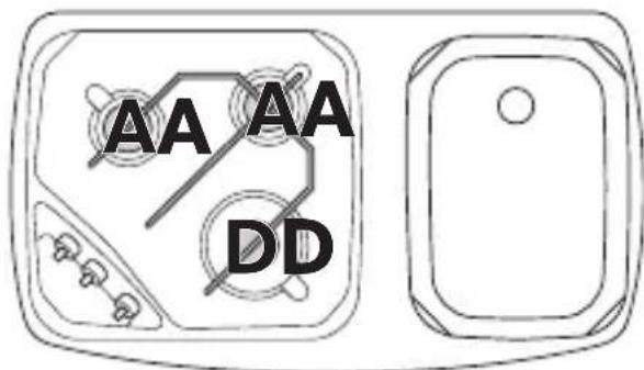

CE99-ZF (HBG2335)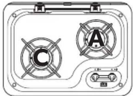
CE 99-DF (HBG3445)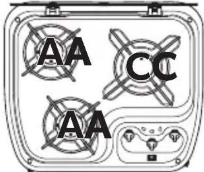
KSK2007R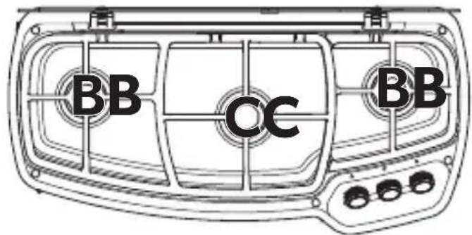
19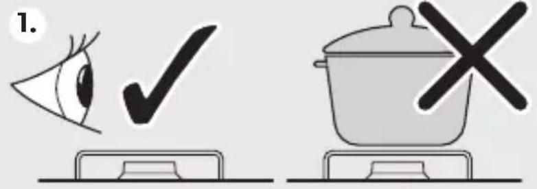
7.
20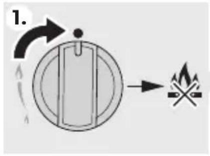
21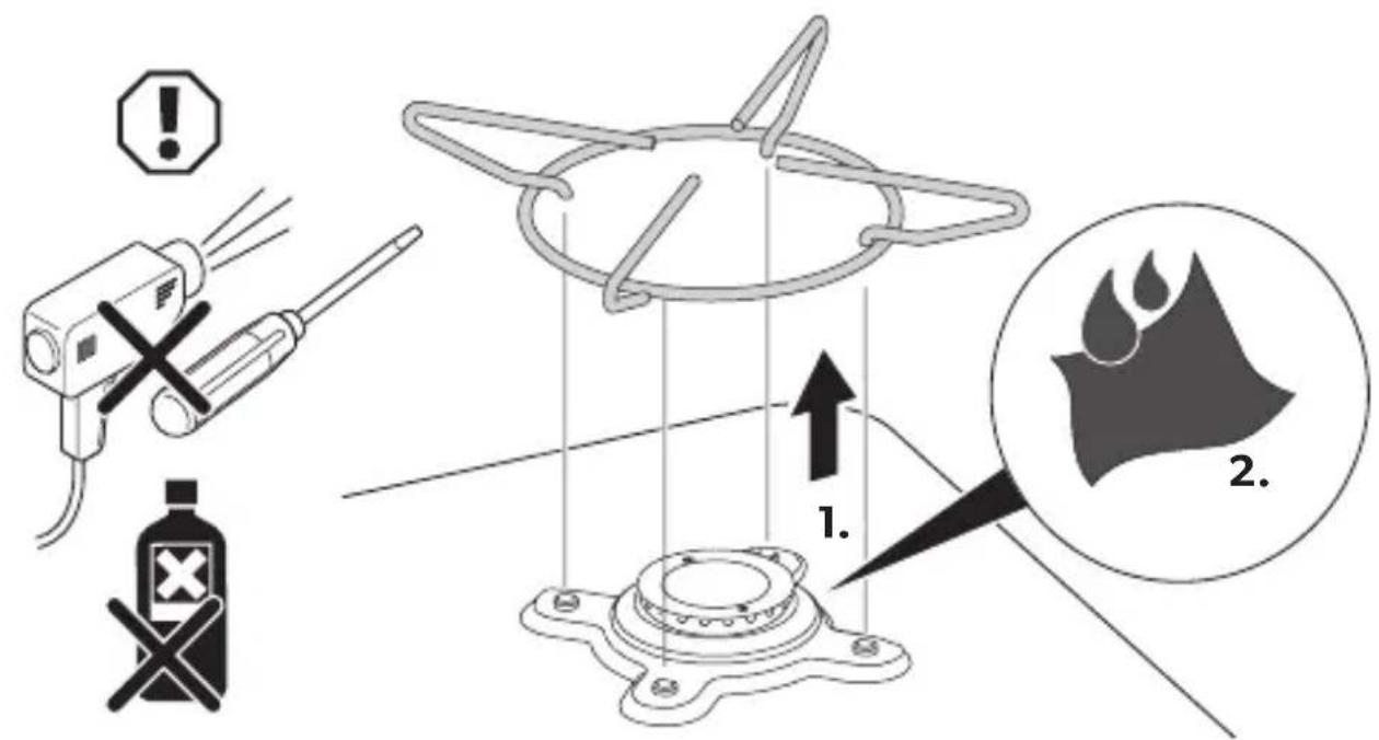
22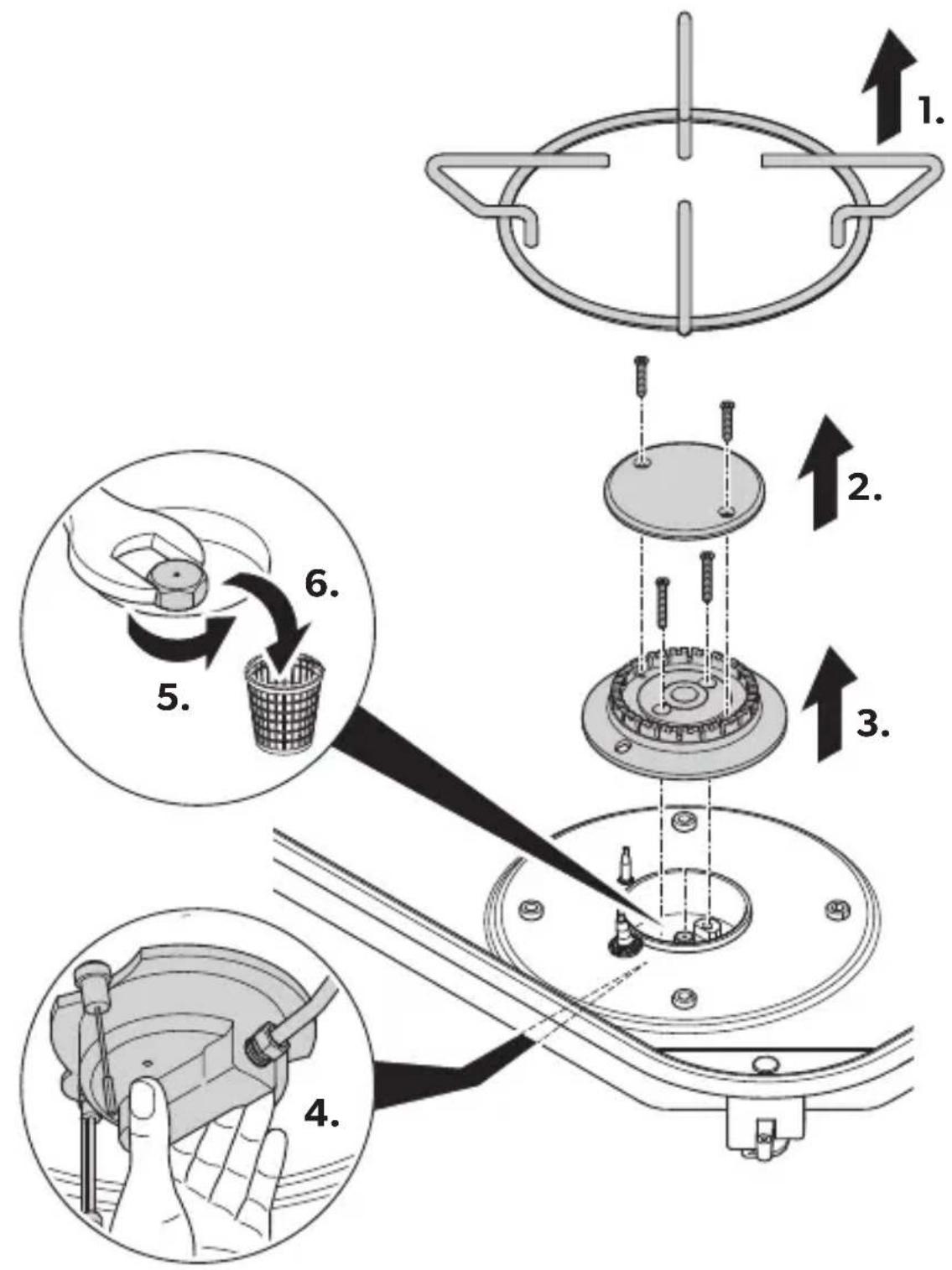
23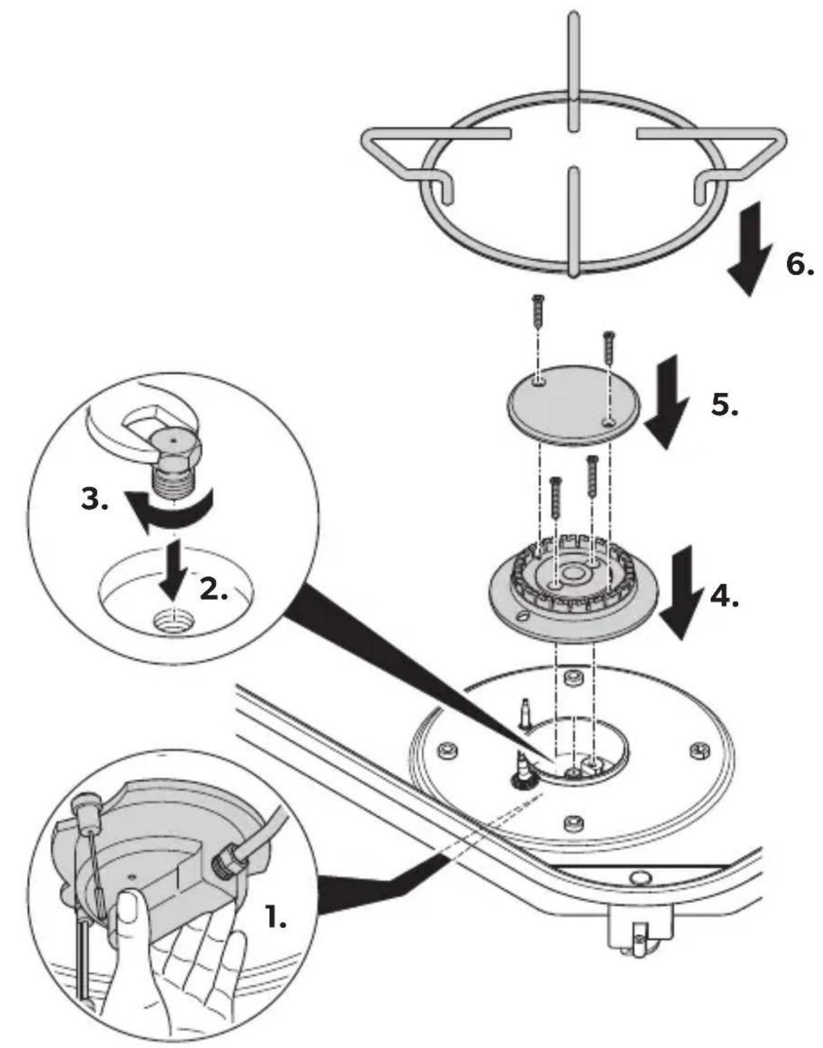
Please read these instructions carefully and follow all instructions, guidelines, and warnings included in this product manual in order to ensure that you install, use, and maintain the product properly at all times. These instructions MUST stay with this product.
By using the product, you hereby confirm that you have read all instructions, guidelines, and warnings carefully and that you understand and agree to abide by the terms and conditions as set forth herein. You agree to use this product only for the intended purpose and application and in accordance with the instructions, guidelines, and warnings as set forth in this product manual as well as in accordance with all applicable laws and regulations. A failure to read and follow the instructions and warnings set forth herein may result in an injury to yourself and others, damage to your product or damage to other property in the vicinity. This product manual, including the instructions, guidelines, and warnings, and related documentation, may be subject to changes and updates. For up-to-date product information, please visit documents.dometic.com.
Contents
1 Explanation of symbols. 20 2 General safety instructions 21 3 Scope of delivery 23 4 Intended use 23 5 Technical description 24 6 Installing the device 24 7 Using the device. 25 8 Cleaning the device 26 9 Maintaining the device. 27 10 Warranty 27 11 Disposal. 27 12 Technical data. 28
1 Explanation of symbols

WARNING!
Safety instruction: Indicates a hazardous situation that, if not avoided, could result in death or serious injury.

CAUTION!
Safety instruction: Indicates a hazardous situation that, if not avoided, could result in minor or moderate injury.
2 General safety instructions
2.1 General safety

WARNING!
- This device must only be repaired by qualified personnel. Improper repairs can result in considerable danger or damage to the device.
- Do not modify this device.
- Observe the gas category and the allowed gas given in chapter "Technical data" on page 28. Do not use any other fuels.
- Keep a suitable fire extinguisher in the immediate vicinity. Ensure that the fire extinguisher is checked by a specialist in regular intervals.
- Do not use or store flammable materials in the device storage drawer or near this device.
- Prior to installation, ensure that the local distribution conditions (nature of the gas and gas pressure) and the adjustment of the device are compatible.
- The adjustment conditions for this device are stated on the label.
- This device is not connected to a combustion products evacuation device. It shall be installed and connected in accordance with current installation regulations. Particular attention shall be given to the relevant requirements regarding ventilation.

CAUTION!
- In case of safety glass cover breakage:
- Shut off immediately all burners and any electrical heating element and isolate the device from the power supply.
- Do not touch the device surface.
- Do not use the device.
2.2 Safety when operating with gas

WARNING!
- Keep flammable substances away from heating and cooking devices, and other light and heat sources.
- Suffocation hazard!
Before switching on the device, ensure that the area is sufficiently ventilated. During operation, there must be air vents with a cross-section of at least 150cm2 in the installation space. These vents can be closed, but must be kept open when the device is operating (see sign located above the device).
- Only operate the device at the pressure specified on the type plate. Only use pressure regulators with a fixed setting that comply with the national regulations.
- Compare the pressure information on the type plate with the pressure information on the propane or butane gas cylinder. If you smell gas:
- Open all windows and leave the room.
- Do not operate any electrical devices or switches, and avoid using open flames that can ignite the gas.
- Close the valve on the gas cylinder and keep it closed until the fault has been rectified.
- Never attempt to find a gas leak with an open flame.
- For countries which are not mentioned in chapter "Technical data" on page 28 (country symbol) refer to national regulations. If necessary the device must be modified according to these national regulations.
2.3 Operating the device safely

WARNING!
- Use the integrated igniter (if available) or long matches or a suitable lighter. The complete ignition process must be visible from above and must not be hidden by pots placed on the stove.
Remove your hand quickly as soon as the burner ignites.
- Wear suitable clothing when operating the device.
Do not wear loose fitting clothing which might catch fire.
- Do not use the device to heat the room.
- Never operate the device
- at petrol stations - on ferry boats
- while transporting the camper van, caravan or motor caravan with a transport vehicle or tow truck
- Do not spray aerosols in the vicinity of this device while it is in operation.

CAUTION!
- Let the device cool down to ambient temperature before you touch it with bare hands.
- Keep the area surrounding the device free of grease, fat, alcoholic substances, plastics and flammable cloths (for example, curtains, towels, kitchen utensils).
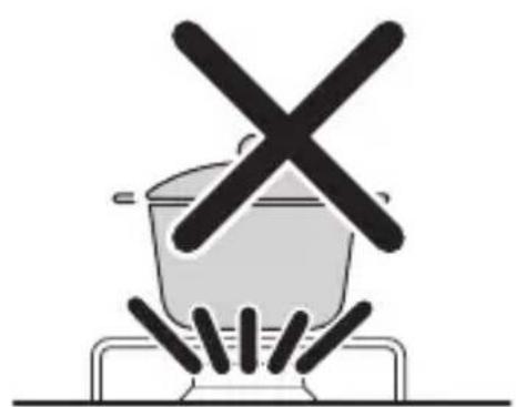
- Only use pots and pans with an even base and a diameter no larger than the grids on the device. The pots and pans must be large enough to cover the flame. If the flames are not covered, items of clothing could catch fire.
- When cooking, ensure that pans and pots are firmly set down.
- Never allow pot handles to extend beyond the edge of the device. Turn pot handles inward, but not extending over other burners. This will minimize the risk of spillage, ignition of flammable materials and/or serious burns.
- Be careful when heating grease or oil. Grease and oil catch fire when exposed to intense heat.
- Risk of breakage!
- Use only dry pot holders to prevent the formation of steam. Do not use towels or similar items instead of pot holders, as these can catch fire.
- Only operate the device when you or another person can attend to it. Pots boiling over can cause smoke and fires.
- Turn off the device before removing the pot or pan.
If available, close the glass cover before beginning a journey. Open the glass cover before igniting the burner.
Glass lids may shatter when heated. Turn off all the burners before shutting the lid.
3 SCOPE OF DELIVERY
- Cooktop (PI80xx, PI90x3, CE99-DF, CE99-ZF, KSK2007R) Combination (MO71x3, MO9x22)
- Fastening screws (depending on the model)
- Siphon and rubber seal (depending on the model)
- Installation and operating manual
4 Intended use
The liquefied gas cooktops in the following model series are intended for installation in a kitchen or worktop in caravans and motor caravans. They are not suitable for boat or marine usage.
The model series covered by this manual are:
- P180x2 PI80x3 (HBG3440)
- P190×3
- MO71x3
- MO9x22
- CE99-DF (HBG3445)
- CE99-ZF (HBG2335)
- KSK2007R
The devices must only be used for cooking food. The device must not be used as a space heater.
This device shall be installed in accordance with the regulations in force and only used in a well ventilated space. Read the instructions before installing or using this device.
This product is only suitable for the intended purpose and application in accordance with these instructions.
This manual provides information that is necessary for proper installation and/or operation of the product. Poor installation and/or improper operating or maintenance will result in unsatisfactory performance and a possible failure.
The manufacturer accepts no liability for any injury or damage to the product resulting from:
- Incorrect assembly or connection, including excess voltage. Incorrect maintenance or use of spare parts other than original spare parts provided by the manufacturer.
- Alterations to the product without express permission from the manufacturer.
- Use for purposes other than those described in this manual.
Dometic reserves the right to change product appearance and product specifications.
5 Technical description
5.1 Function
The device is equipped with an automatic flame monitoring device which automatically interrupts the gas supply after approx. 20 seconds if the flame goes out.
5.2 Specifications for the different models
The devices are available in different versions:
- CE99-ZF: Cooktop with two burners and safety glass cover PI80xx: Cooktop with two to three burners and safety glass cover
- CE99-DF: Cooktop with three burners and safety glass cover
- KSK2007R: Cooktop with three burners and safety glass cover PI90x3: Cooktop with three burners and safety glass cover
- MO71x3: Combination with three burners, safety glass cover and a sink
- MO9x22: Combination with two burners, safety glass cover and a sink
The safety glass cover can be used as a work surface when it is closed.
5.3 Control panel
See fig. 1, page 3
6 Installing the device

WARNING!
Assembly and installation of the device must only be carried out by specialists. Incorrect assembly and installation can result in serious hazards due to the escape of gas.
6.1 Selecting the installation location
When selecting the installation location, observe the following instructions:
- Consider the volume of air required for combustion (chapter "Technical data" on page 28).
- During operation, there must be air vents with a cross-section of at least 150 cm² in the installation room.
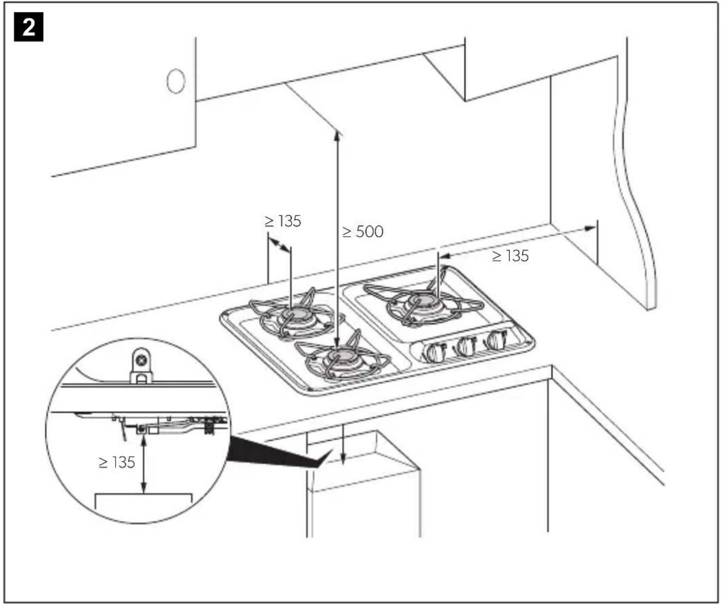
- Make sure that minimum distances (fig. 2, page 4) are observed.
- Ensure that there are no drafts at the installation location.
6.2 Installing the device
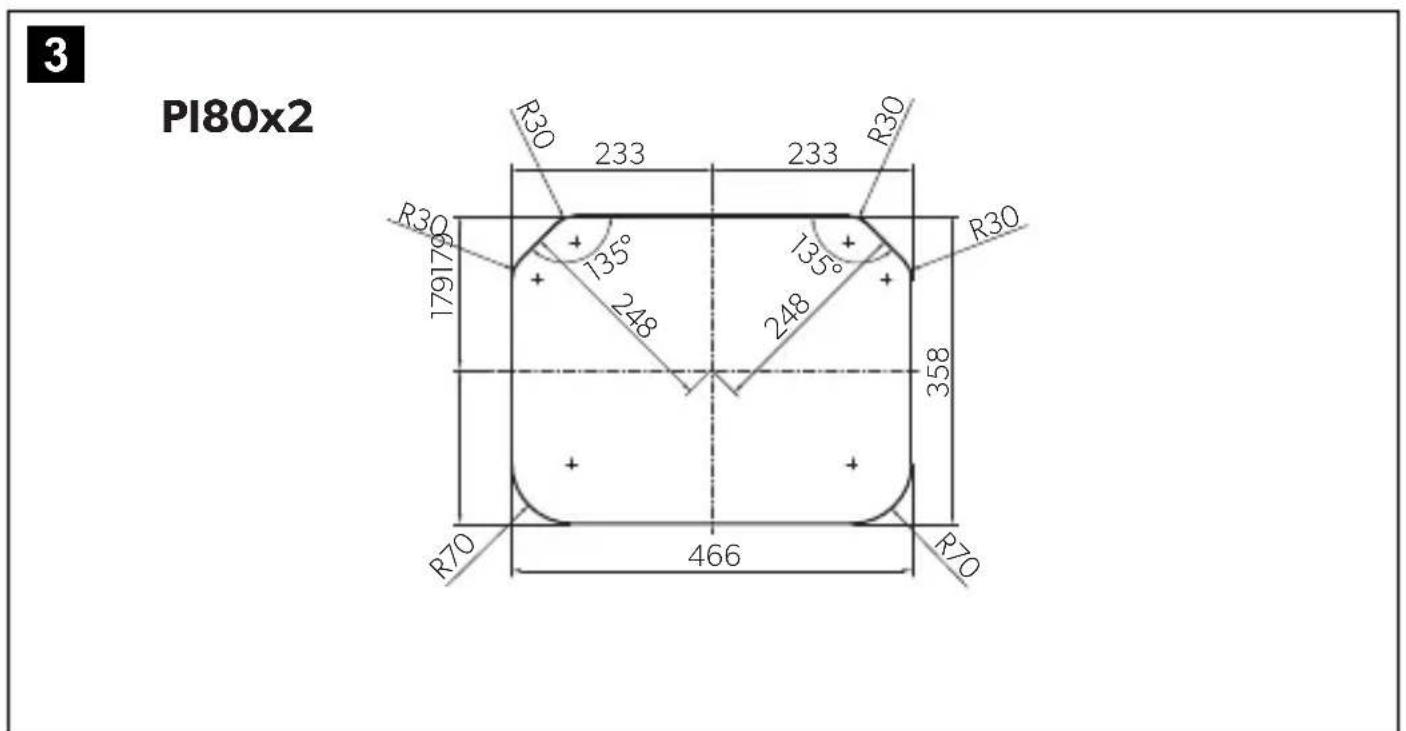
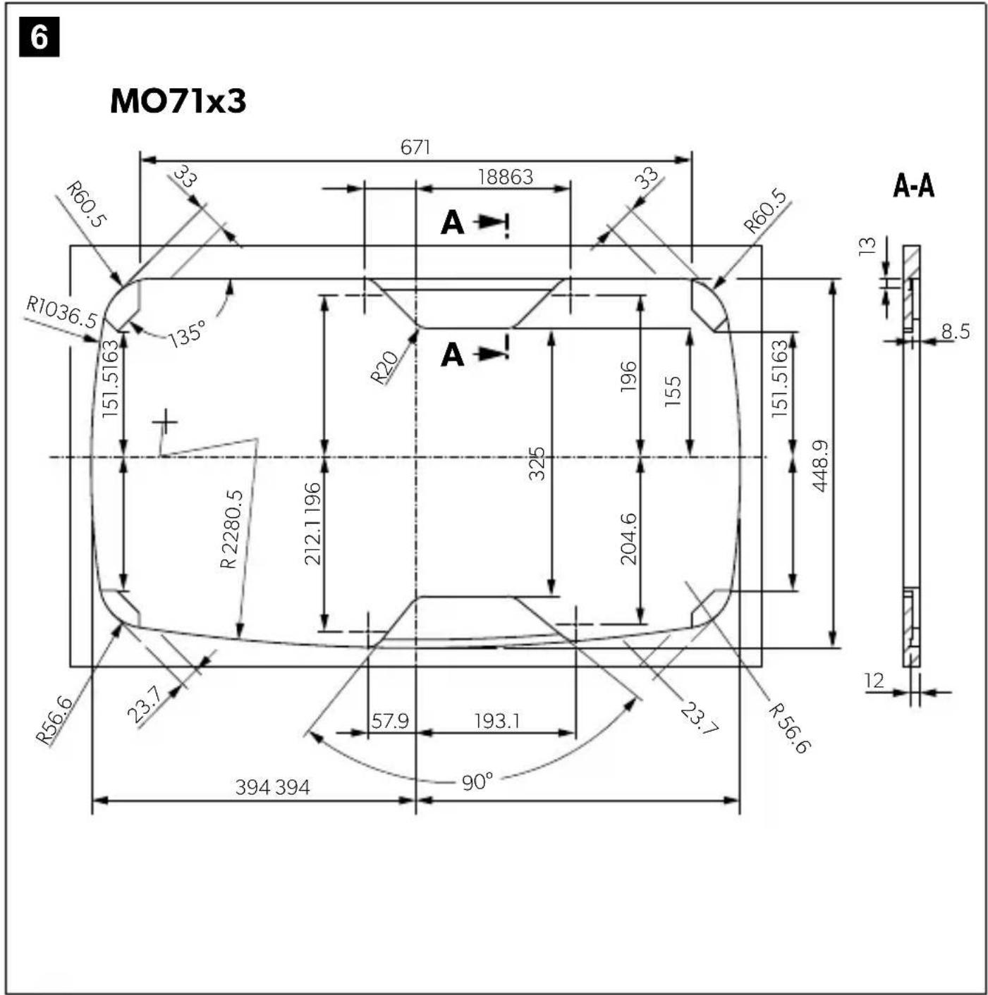
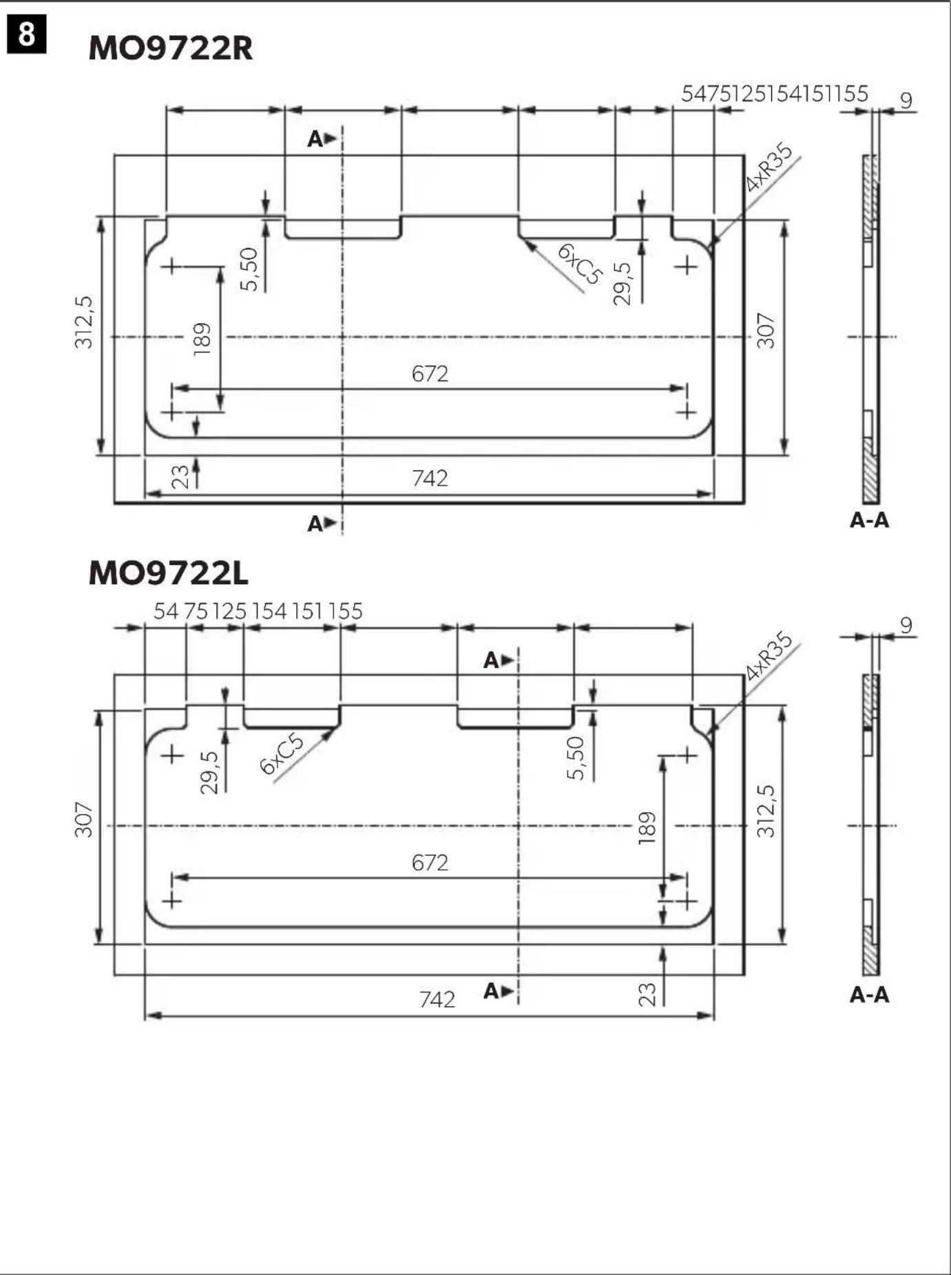
- Create a cutout according to the installation drawing:
PI80x2: fig. 3, page 4 - PI80x3: fig. 4, page 5 - PI90x3: fig. 5, page 5 - MO71x3: fig. 6, page 6 - MO9222: fig. 7, page 7 - MO9722: fig. 8, page 8 - CE-99-ZF: fig. 9, page 9 - CE99-DF: fig. 10, page 9 - KSK2007R: fig. 11, page 10
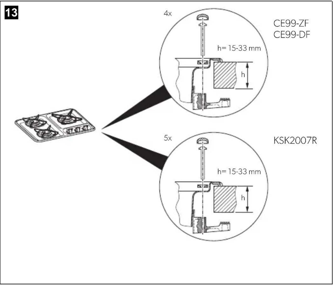
- Affix the device to the worktop using the screws (fig. 12, page 10 - fig. 14, page 12).
6.3 Connecting the device to the gas supply

WARNING! Risk of injury
Only use propane or butane gas cylinders with a certified pressure reduction valve and suitable head. Compare the pressure information on the type plate with the pressure information on the propane or butane gas cylinder.
You must use a rigid gas line for the connection.
Observe the following instructions for the connection:
- Observe the national requirements.
- Use only steel pipe Ø8 × 1 mm (welded, seamless steel or stainless steel).
- Fasten the gas line to the side or rear wall of the surrounding furniture parts so that no loads are placed on the actuators.
- The entire gas line must be free of stress.
- Connect the pipes as shown (fig. 15, page 13).
- Attach a sign above the device with the following text:
"WARNING!
When cooking, additional ventilation must be provided, for example, by opening windows near the device.
The device must not be used as a space heater."
- Open the gas supply.

WARNING! Risk of injury
Never check for leaks with an open flame or near sources of ignition.
- Check all connections for leaks with leak spray.
There are no leaks if no bubbles form.
6.4 Connecting the device to the power supply
(models with electronic ignition only)
- Connect the device as shown (fig. 16, page 13).
- Add a 1 A fuse in the plus line near the battery.
7 Using the device

CAUTION!
Do not shut lid when burner is alight.
7.1 Igniting a burner

WARNING! Risk of injury
The complete ignition process must be visible from above and must not be hidden by pots placed on the stove.

NOTICE!
The flame must not extend beyond the edge of the pot. Centre the pot above the burner ensuring stability on the pot grid (see page 3).
- Choose a pot according to the following table:
| Burner (fig. 17, page 14 – fig. 18, page 15) | Pot diameter |
| A-B 9-15 cm | S |
| C 10-18 cm | M |
| D 16-22 cm | L |
KSK2007R only: The maximum permissible pot sizes are 20 cm for the left burner, 18 cm for the right burner, 25 cm for the central burner. The pot size icons from left to right are S, L, S.
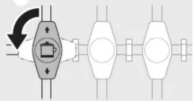
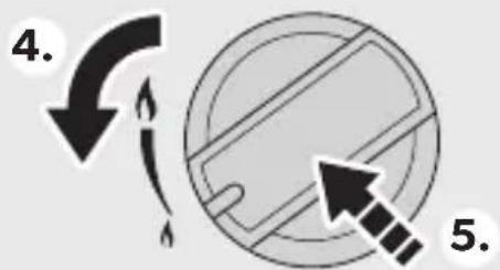
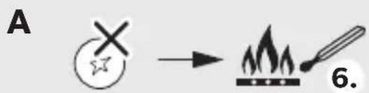
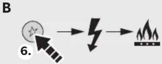
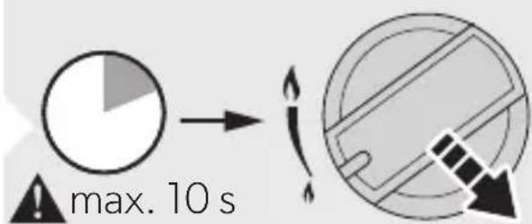
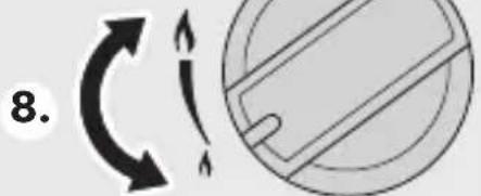
- Ignite a burner as shown (fig. 19, page 16).
7.2 Switching off the device
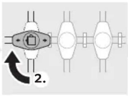
Switch off the device as shown (fig. 20, page 17).
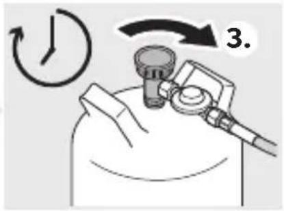
7.3 Replacing the gas cylinder

WARNING! Risk of injury
Only replace the gas cylinder when there is good ventilation.
Make sure that there is no source of ignition nearby.
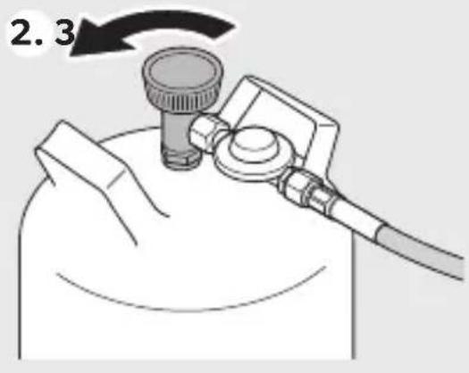
Only change the gas cylinder when the device is not in use and the gas supply to the device is switched off.
- Switch the device off by turning the knob to the zero setting.
- Close the valve on the gas cylinder.
- Replace the gas cylinder according to the instructions from the gas fitting manufacturer.
8 Cleaning the device

CAUTION! Hot surface
The surface may still be hot. Keep children away.
Let the device cool down to ambient temperature before you touch it with bare hands.

NOTICE!
Do not use any sharp or hard objects for cleaning since they may damage the device.
Only use standard commercial cleaning agents.
Do not use a steam cleaner to clean the device.
Clean the device as shown (fig. 21, page 17).
9 Maintaining the device
9.1 Annual safety check
For safety reasons, have the device checked by an expert every year for proper function. Any defects must be repaired.
9.2 Replacing the nozzles

WARNING! Risk of injury
The nozzles must only be replaced by qualified specialists. Incorrect assembly and installation can result in serious hazards due to the escape of gas.
Replace the nozzles as shown:
Disassembly: fig. 22, page 18 Assembly: fig. 23, page 19
10 Warranty
The statutory warranty period applies. If the product is defective, please contact your retailer or the manufacturer's branch in your country (see dometic.com/dealer).
For repair and warranty processing, please include the following documents when you send in the product:
- A copy of the receipt with purchasing date
- A reason for the claim or description of the fault. Note that self-repair or non-professional repair can have safety consequences and might void the warranty.
11 Disposal

Place the packaging material in the appropriate recycling waste bins wherever possible.
Consult a local recycling center or specialist dealer for details about how to dispose of the product in accordance with the applicable disposal regulations. The product can be disposed free of charge.
12 Technical data
See fig. 17, page 14 - fig. 18, page 15:
| Cooktop | |
| Gas category: Category I | 3 B/P(30) |
| Connection pressure: | AT, DE, BG, CY, DK, EE, FI, GR, HU, IS, LT, LV, MT, NL, NO, RO, SE, SI, SK, AL, HR, MK, TR: 30 mbar propane (G31) 30 mbar butane (G30) |
| Gas category: Category I | 3+, propane/butane |
| Connection pressure: | BE, CH, CY, CZ, ES, FR, GB, GR, IE, IT, LT, PL, PT, SI, SK, AL, MK, TR: 37 mbar propane (G31) 28 - 30 mbar butane (G30) |
| Connection voltage (models with electronic ignition only): | 12 V= (1 A fuse) |
| Inspection/certification: | CE |
| Model | Burner A | Burner B | ||||||
| *** | *** | *** | *** | |||||
| PI80X2 | 0.53 | 1.1 | 80 | 79 | - | - | - | - |
| PI80X3 | 0.53 | 1.1 | 80 | 79 | - | - | - | - |
| PI90X3 | 0.53 | 1.1 | 80 | 79 | - | - | - | - |
| MO9722L,MO9722R | 0.53 | 1.1 | 80 | 79 | - | - | - | - |
| MO71X3 | 0.53 | 1.1 | 80 | 79 | - | - | - | - |
| CE99-ZF | 0.53 | 1.1 | 80 | 79 | - | - | - | - |
| CE99-DF | 0.53 | 1.1 | 80 | 79 | - | - | - | - |
| KSK2007RMO9222L,MO9222R | - | - | - | - | 0.50 | 1.0 | 73 | 71 |
*Injector mm ** Power kW *** Gas consumption (G30) g/h **** Gas consumption (G31) g/h
| Model | Burner C | Burner D | ||||||
| *** | *** | **** | *** | |||||
| PI80X2 | --- | -0.691.8 | 131129 | |||||
| PI80X3 | 0.651.6 | 116114 | --- | |||||
| PI90X3 | --- | -0.691.8 | 131129 | |||||
| MO9722L,MO9722R | --- | -0.691.8 | 131129 | |||||
| MO9222L,MO9222R | 0.651.6 | 116114 | --- | |||||
| MO71X3 | --- | -0.691.8 | 131129 | |||||
| CE99-ZF | 0.651.6 | 116114 | --- | |||||
| CE99-DF | 0.651.6 | 116114 | --- | |||||
| KSK2007R | 0.651.6 | 116114 | --- | |||||
* Injector mm ** Power kW *** Gas consumption (G30) g/h *** Gas consumption (G31) g/h
5 Technical description
5.1 Function
6 Installation of apparatus

WARNING!
6.2 Installation of apparatus
- Make a cutout according to the installation drawing:
PI80x2: fig. 3, page 4; PI80x3: fig. 4, page 5; PI90x3: fig. 5, page 5 - MO71x3: fig. 6, page 6 - MO9222: fig. 7, page 7 - MO9722: fig. 8, page 8 - CE-99-ZF: fig. 9, page 9 - CE99-DF: fig. 10, page 9 - KSK2007R: fig. 11, page 10
- Fasten the apparatus to the worktop with the screws (fig. 12, page 10 - fig. 14, page 12).
- Worktop (PI80xx, PI90x3, CE99-DF, CE99-ZF, KSK2007R) Combination (MO71x3, MO9x22) Mounting screws (depending on model) Sealing strip (depending on model) Operating and installation instructions
Intended use
The appliances described in this manual are intended for installation in kitchens and for operation on work surfaces in homes and similar places. They are not intended for installation in caravans or boats.
Series described in this manual:
- P180x2 PI80x3 (HBG3440) PI90x3
- MO71x3
- MO9x22
- CE99-DF (HBG3445)
- CE99-ZF (HBG2335)
- KSK2007R
The device may only be used when it is ready for use. The device must not be used as a heater.
The device must be installed in accordance with applicable regulations and used only in a well-ventilated room. Read the instructions before installing or using this device.
This product is intended for use as intended and in accordance with this instruction manual.
This instruction manual contains information necessary for correct installation and/or operation. Incorrect installation or improper operation or maintenance may lead to unsatisfactory performance and possible failure.
The manufacturer is not liable for any injuries or damage to the product resulting from the following:
- Incorrect assembly or connection, including overvoltage
- Incorrect maintenance or use of spare parts other than original spare parts provided by the manufacturer
- Modifications to the product made without the explicit permission of the manufacturer
- Use for purposes other than those specified in this instruction manual
Dometic reserves the right to change the product's technical specifications.
6.2 Installation of the device
- Make the cutout according to the installation drawing:
P180x2: fig. 3, p. 4 - P180x3: fig. 4, p. 5 - P190x3: fig. 5, p. 5 - MO71x3: fig. 6, p. 6 - MO9222: fig. 7, p. 7 - MO9722: fig. 8, p. 8 - CE-99-ZF: fig. 9, p. 9 - CE99-DF: fig. 10, p. 9 - KSK2007R: fig. 11, p. 10
- Attach the device to the worktop using screws (Fig. 12, page 10 - Fig. 14, page 12).
6.3 Connecting the appliance to the gas supply system

The device must not be used as a heater.
- Open the gas valve.

It is forbidden to check for leaks with an open flame or near sources of ignition.
- Check the tightness of all connections using a leak detection spray.
Tightness is ensured if no bubbles form.
6.4 Connecting the device to the electrical network (only for models with electric ignition)
1. Connect the device as shown in the figure (Fig. 16, page 13). 2. Add a 1 A fuse to the positive cable near the battery.
7 Use of the device

WARNING!
Do not close the lid while the burner is on.
7.1 Igniting the burner

WARNING! Risk of injury!
The entire ignition process must be visible from above and must not be hidden by pots placed on the grate.

The flame must not extend beyond the base of the pan. Center the pan on the burner, ensuring stability by placing it on the grate (see page 3).
- Choose the pan according to the following table:
- Light the burner as shown in the figure (fig. 19, page 16).
7.2 Switching off the appliance
Switch off the device as shown in the figure (fig. 20, page 17).
7.3 Replacing the gas cylinder

WARNING! Risk of injury!
Replace the gas cylinder only in a well-ventilated area.
Make sure there are no sources of ignition nearby.
Replace the gas cylinder only when the device is not in use and the gas supply to the device is shut off.
- Switch off the device by turning the knob to the zero position. 2. Close the valve on the gas cylinder.
- Replace the gas cylinder in accordance with the instructions of the gas equipment manufacturer.
8 Cleaning the device

CAUTION! Hot surface!
The surface may still be hot. Do not allow children to touch it.
Before touching the device with unprotected hands, allow it to cool down to the temperature of the surrounding medium.

WARNING!
Do not use sharp or hard instruments for cleaning, as they may damage the device.
Use only standard commercial cleaning agents.
Do not use solvents for cleaning the device.
Clean the device as shown in the figure (Fig. 21, p. 17).
9 Technical maintenance of the device
9.1 Annual safety check
For safety reasons, the device must be checked annually by a specialist for proper operation. Any defects must be repaired.
9.2 Replacing nozzles

See Fig. 17, p. 14 - Fig. 18, p. 15:
| МODEЛь | КонфоркA | КонфоркВ | ||||||
| *** | *** | *** | *** | |||||
| PI80X2 | 0 | , | 5 | 3 | 1 | , | 1 | 8 |
| PI80X3 | 0 | , | 5 | 3 | 1 | , | 1 | 8 |
| PI90X3 | 0 | , | 5 | 3 | 1 | , | 1 | 8 |
| MO9722L,MO9722R | 0 | , | 5 | 3 | 1 | , | 1 | 8 |
| MO71X3 | 0 | , | 5 | 3 | 1 | , | 1 | 8 |
| CE99-ZF | 0 | , | 5 | 3 | 1 | , | 1 | 8 |
| CE99-DF | 0 | , | 5 | 3 | 1 | , | 1 | 8 |
| KSK2007RMO9222L,MO9222R | - | - | - | - | 0,50 | 1,0 | 73 | 71 |
* Injector MM ** Power kW *** Gas consumption (G30) g/h *** Gas consumption (G31) g/h
| Модень | КонфоркaС | КонфоркaD | ||||||
| *** | *** | *** | *** | |||||
| PI80X2 | --- | -0,691,8 | 131129 | |||||
| PI80X3 | 0 | 6 | 5 | 1 | 6 | |||
| PI90X3 | --- | -0,691,8 | 131129 | |||||
| MO9722L,MO9722R | --- | -0,691,8 | 131129 | |||||
| MO9222L,MO9222R | 0 | 6 | 5 | 1 | 6 | |||
| MO71X3 | --- | -0,691,8 | 131129 | |||||
| CE99-ZF | 0 | 6 | 5 | 1 | 6 | |||
| CE99-DF | 0 | 6 | 5 | 1 | 6 | |||
| KSK2007R | 0 | 6 | 5 | 1 | 6 | |||
* Injector MM
** Power kW
**Gas connection (G30) r/4
*** Gas connection (G31) r/4
dometic.com/sales-offices


- HOB AND COOKING HOBS AND COMBINATIONS
- EN
- COOKTOPS AND COMBINATIONS
- DE
- PL
- CONTENTS
- EXPLANATION OF SYMBOLS
- WARNING
- CAUTION
- GENERAL SAFETY INSTRUCTIONS
- GENERAL SAFETY
- SAFETY WHEN OPERATING WITH GAS
- OPERATING THE DEVICE SAFELY
- RISK OF BREAKAGE
- SCOPE OF DELIVERY
- INTENDED USE
- TECHNICAL DESCRIPTION
- FUNCTION
- SPECIFICATIONS FOR THE DIFFERENT MODELS
- CONTROL PANEL
- INSTALLING THE DEVICE
- SELECTING THE INSTALLATION LOCATION
- CONNECTING THE DEVICE TO THE GAS SUPPLY
- WARNING! RISK OF INJURY
- CONNECTING THE DEVICE TO THE POWER SUPPLY
- (MODELS WITH ELECTRONIC IGNITION ONLY)
- USING THE DEVICE
- IGNITING A BURNER
- NOTICE
- SWITCHING OFF THE DEVICE
- REPLACING THE GAS CYLINDER
- CLEANING THE DEVICE
- CAUTION! HOT SURFACE
- MAINTAINING THE DEVICE
- ANNUAL SAFETY CHECK
- REPLACING THE NOZZLES
- WARRANTY
- DISPOSAL
- TECHNICAL DATA
- INSTALLATION OF APPARATUS
- INSTALLATION OF THE DEVICE
- CONNECTING THE APPLIANCE TO THE GAS SUPPLY SYSTEM
- CONNECTING THE DEVICE TO THE ELECTRICAL NETWORK (ONLY FOR MODELS WITH ELECTRIC IGNITION)
- USE OF THE DEVICE
- IGNITING THE BURNER
- SWITCHING OFF THE APPLIANCE
- TECHNICAL MAINTENANCE OF THE DEVICE
- REPLACING NOZZLES
Brand : DOMETIC
Model : PI8022
Category : Cooker