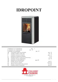
IDROPOINT - Boiler EDILKAMIN - Free user manual and instructions
Find the device manual for free IDROPOINT EDILKAMIN in PDF.


| Product type | Pellet boiler (thermostove) |
| Brand | Edilkamin |
| Model | IDROPOINT |
| Fuel | Wood pellet diameter 6 mm |
| Nominal power | 11.5 kW |
| Water power | 8.3 kW |
| Overall efficiency | 90.1 % |
| CO emission (13% O₂) | 0.013 % |
| Maximum pressure | 2 bar |
| Flue gas temperature | 140 °C |
| Autonomy | 5 to 18 hours |
| Pellet consumption | 0.8 to 2.7 kg/h |
| Tank capacity | 14 kg |
| Heatable volume | 300 m³ |
| Flue pipe diameter | 80 mm (male) |
| Air intake diameter | 40 mm (male) |
| Weight with packaging | 142 kg |
| Power supply | 230 V ±10% 50 Hz |
| Average electrical power consumption | 150 W |
| Electrical power at ignition | 400 W |
| Electrical protection | Fuse F4 AL 250 V~ |
| Safety devices | Thermocouple, differential pressure switch, safety thermostat, water probe, relief valve, pressure gauge |
| Daily maintenance | Cleaning the crucible and emptying ashes |
| Seasonal maintenance | By authorized technical service center |
Frequently Asked Questions - IDROPOINT EDILKAMIN
User questions about IDROPOINT EDILKAMIN
0 question about this device. Answer the ones you know or ask your own.
Ask a new question about this device
Download the instructions for your Boiler in PDF format for free! Find your manual IDROPOINT - EDILKAMIN and take your electronic device back in hand. On this page are published all the documents necessary for the use of your device. IDROPOINT by EDILKAMIN.
USER MANUAL IDROPOINT EDILKAMIN
natural_image
Exterior view of a modern electric stove with visible flame inside the glass (no text or symbols)UK Installation, use and maintenance
INFORMAZIONI PER LA SICUREZZA
IDROPOINT NON DEVE MAI FUNZIONARE SENZA ACQUA NELL'IMPIANTO.
UNA EVENTUALE ACCENSIONE "A SECCO" COMPRO-METTEREBBE LA TERMOSTUFA.
IDROPOINT DEVE FUNZIONARE CON UNA PRESSIONE DI UN 1,5 BAR CIRCA.
natural_image
Cross-sectional diagram of a device casing with internal components and an arrow indicating direction (no text or symbols)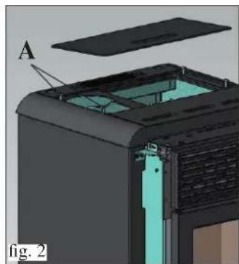
natural_image
3D cutaway view of a device showing internal components and a labeled section (A), no text or symbols present.USCITA FUMI
natural_image
3D cutaway diagram of a device showing internal components and housing (no text or symbols)natural_image
Cross-sectional diagram of a mechanical device with labeled component C, shown in 3D view (no text or symbols beyond labels)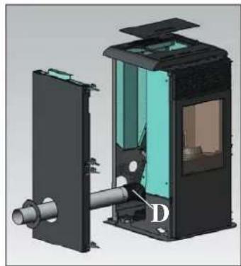
natural_image
3D cutaway view of a mechanical device showing internal components and housing (no text or symbols)COLLEGAMENTO USCITA FUMI DAL RETRO
natural_image
3D diagram of a device with labeled component E, shown in two views (Fig. 7 and Fig. 8), no readable text or symbols beyond labels.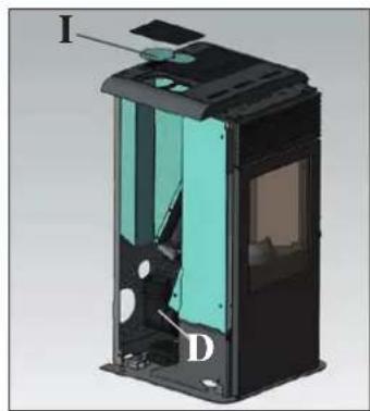
natural_image
3D cutaway view of a device showing internal components labeled I, D, and a highlighted section (no text or symbols beyond labels)COLLEGAMENTO USCITA FUMI DAL TOP
natural_image
3D rendering of a black industrial device with internal cutaway view showing internal structure (no text or symbols)UNA VOLTA TERMITA L'OPERAZIONE DI COLLEGAMENTO DEL TUBO USCITA FUMI ALLA CANNA FUMARIA RIMONTARE IL FIANCO IN METALLO SINISTRO E POI PROSEGUIRE CON L'ASSEMBLAGGIO DEL RIVESTIMENTO (vedi pag 10).
ASSEMBLAGGIO
RIVESTIMENTO
natural_image
3D mechanical assembly diagram showing a red cylindrical component with labeled parts E and F, no readable text or symbols beyond labelsALLACCIAMENTI IDRAULICI
(RISERVATO CENTRO ASSISTENZA TECNICA)
- IDROPOINT NON DEVE MAI FUNZIONARE SENZA ACQUA NELL'IMPIANTO.
• LA PRESSIONE DI ESERCIZIO DEVE ESSERE DI 1,5 BAR CIRCA. - UNA EVENTUALE ACCENSIONE “A SECCO” COMPROMETTEREBBE LA TERMOSTUFA.
natural_image
3D model of a red industrial fan or oven with internal compartments and a black plastic cover (no text or symbols visible)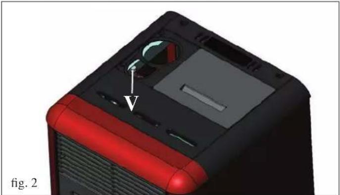
natural_image
3D model of a red and black computer case with a dial indicator and arrow pointing to a component (no text or symbols on the device itself)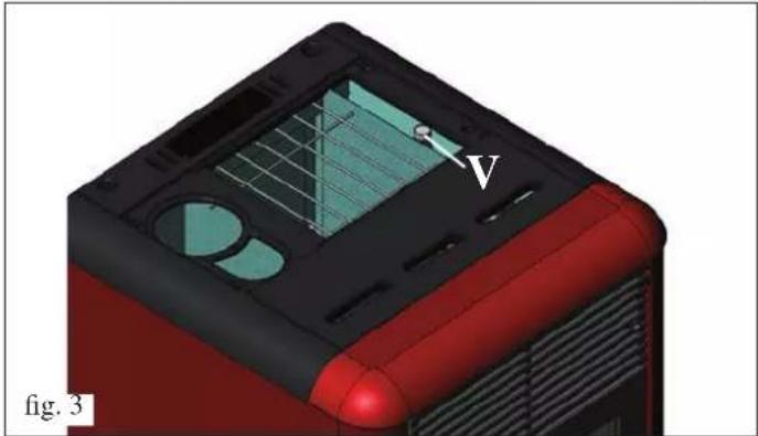
natural_image
3D model of a red and black device casing with internal components, labeled 'fig. 3' (no readable text or symbols beyond label)
NOTE:
natural_image
3D rendering of a mechanical device with a labeled component (1) inside, showing internal components and no visible text or symbols.fig. A
natural_image
3D rendering of a mechanical device inside a storage unit with red pipes and a numbered label (no text or symbols on the device itself)fig. B
natural_image
3D rendering of a red industrial machine with a metallic component inside, showing internal components and a numbered label (3) on the door (no text or symbols on the device itself)fig. C
natural_image
3D diagram of a red industrial machine with labeled components and directional arrows (no text or symbols beyond labels)fig. D
MANUTENZIONE
natural_image
3D CAD model of a mechanical assembly with a cylindrical component mounted on a base, shown in an open view (no text or symbols visible)CONSIGLI PER POSSIBILI INCONVENIENTI
natural_image
3D cutaway view of a device showing internal structure and housing (no text or symbols)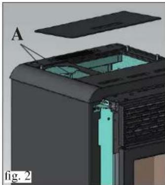
natural_image
3D cutaway view of a device showing internal components and a labeled section A (no text or symbols beyond label)natural_image
3D cutaway diagram of a device showing internal components and housing (no text or symbols)natural_image
3D cutaway diagram of a mechanical device with labeled component C, showing internal structure and housing (no text or symbols beyond labels)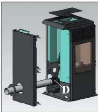
natural_image
3D mechanical assembly diagram showing internal components with no visible text or symbolsnatural_image
3D diagram of a device with labeled component E, shown in two views (Fig. 7 and Fig. 8), no readable text or symbols beyond labels.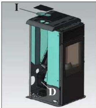
natural_image
3D cutaway view of a device casing with labeled parts I, D, and D (no text or symbols beyond labels)natural_image
3D rendering of a black industrial device with internal structure and ventilation duct (no text or symbols visible)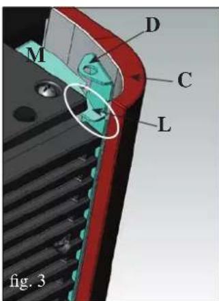
REVESTIMIENTO
natural_image
3D mechanical assembly diagram showing a red component with labeled parts E, F, and F' (no text or symbols beyond labels)natural_image
3D model of a red and black electronic device casing with ventilation grilles and a plastic cover (no text or symbols visible)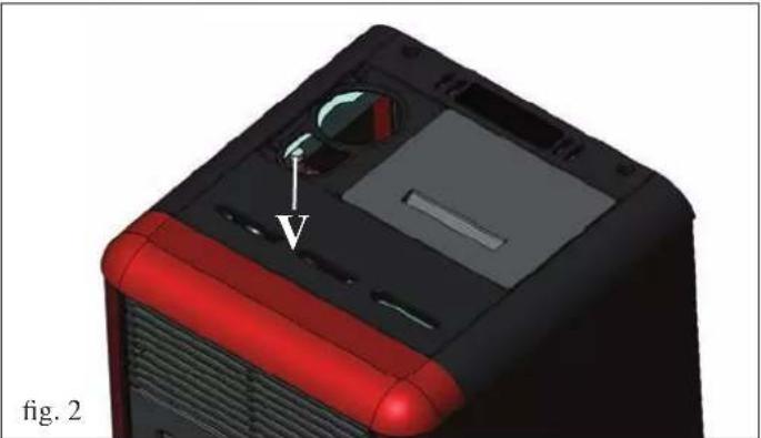
natural_image
3D model of a computer tower with red and black casing, showing internal components and a labeled component (V), no text or symbols present.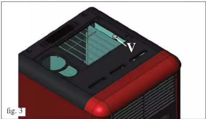
natural_image
3D model of a red and black device casing with internal components, labeled 'fig. 3' and an arrow pointing to a component (no readable text or symbols beyond labels)
NOTAS:
natural_image
3D rendering of a mechanical device with a labeled component (1) and open door, showing internal components without any text or symbols.fig. A

natural_image
3D rendering of a mechanical assembly inside a transparent enclosure, showing internal components and no visible text or symbols.fig. B
MANTENIMIENTO SEMANAL
natural_image
3D rendering of a red industrial machine with a labeled component (3) and internal components, no visible text or symbols.fig. C
natural_image
3D rendering of a red industrial oven with labeled components and airflow direction arrow (no text or symbols beyond labels)fig. D
MANTENIMIENTO
MANTENIMIENTO ESTACIONAL (a cargo del distribuidore)
Consiste en la:
natural_image
3D rendering of a mechanical assembly with a cylindrical component mounted on a base, shown in an open view (no text or symbols visible)CONSEJOS PARA POSIBLES INCONVENIENTES
INFORMAÇÕES PARA A SEGURANÇA
IDROPOINT NUNCA DEVE FUNCIONAR SEM ÁGUA NO CIRCUITO.
UMA EVENTUAL LIGAÇÃO “A SECO” PODE COMPROMETER A ESTUFA TÉRMICA.
natural_image
Cross-sectional diagram of a device showing internal components and airflow direction (no text or symbols)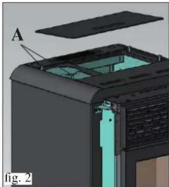
natural_image
3D cutaway view of a device showing internal components and a labeled section (A), no readable text or symbols present.SAÍDAS FUMOS
natural_image
3D cutaway diagram of a device showing internal components and housing (no text or symbols)natural_image
3D cutaway diagram of a mechanical device with labeled component C, showing internal structure and housing (no text or symbols beyond labels)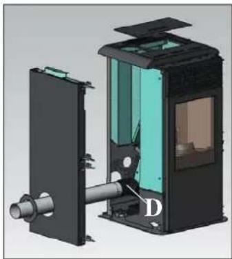
natural_image
3D mechanical assembly diagram showing internal components with labeled part D (no text or symbols beyond label)natural_image
3D diagram of a device with labeled component E, shown in two views (Fig. 7 and Fig. 8), no readable text or symbols beyond labels.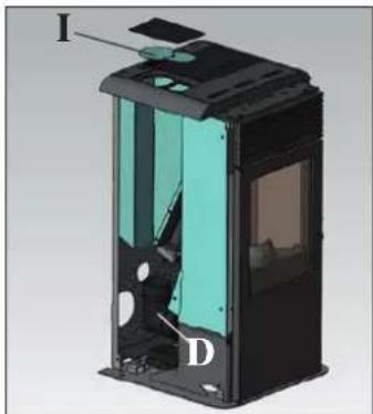
natural_image
3D cutaway view of a device showing internal components labeled I and D (no text or symbols beyond labels)natural_image
3D rendering of a black industrial device with internal structure and ventilation duct (no text or symbols visible)MONTAGEM
REVESTIMENTO
natural_image
3D CAD model of a mechanical component with red and black parts, showing internal structure and mounting holes (no text or symbols)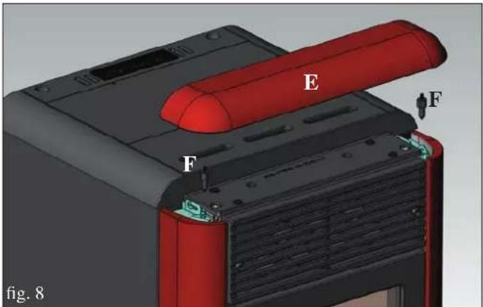
natural_image
3D mechanical assembly diagram showing a red cylindrical component with labeled parts E and F, no readable text or symbols beyond labelsLIGAÇÕES HIDRÁULICAS
(RESERVADO CENTRO ASSISTÊNCIA TÉCNICA)
natural_image
3D model of a red and black electronic device casing with ventilation grilles and a star-shaped component above it (no text or symbols)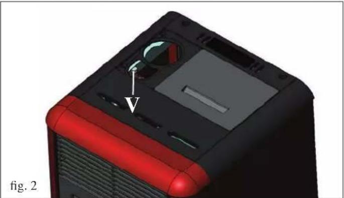
natural_image
3D model of a computer tower with red and black casing, showing internal components and a labeled component (V), no text or symbols present.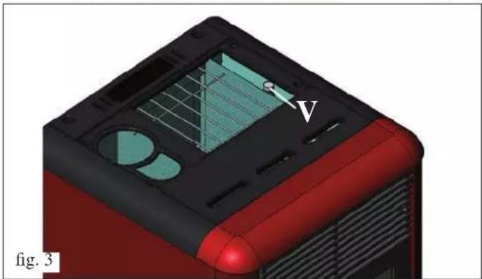
natural_image
3D model of a red and black device casing with internal components and a labeled point 'V', shown in perspective view (no text or symbols on the object itself)
OBSERVAÇÕES:
natural_image
3D rendering of a mechanical device with a labeled component (1) and open door, showing internal components without any text or symbols.fig. A
natural_image
3D rendering of a mechanical device inside a transparent enclosure, showing internal components and no visible text or symbols.fig. B
MANUTENÇÃO SEMANAL
natural_image
3D rendering of a red industrial machine with a cylindrical component inside, showing internal components and a labeled part (3), no text or symbols present.fig. C
natural_image
3D diagram of a red industrial oven with labeled components and airflow direction arrow (no text or symbols beyond numbers)fig. D
MANUTENÇÃO
natural_image
Interior view of a portable stove or oven with two labeled components (A and B), showing internal structure and no visible text or symbols.fig. 1 fig. 2
natural_image
3D rendering of a mechanical component with a cylindrical housing and mounting bracket (no visible text or symbols)CONSELHOS PARA POSSÍVEIS INCONVENIENTES
natural_image
Cross-sectional diagram of a mechanical device with internal components and labeled section (no readable text or symbols)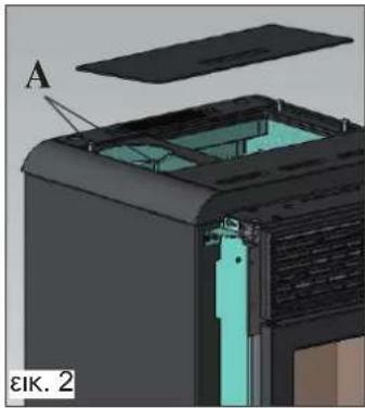
natural_image
3D mechanical assembly diagram showing internal components with labeled section A (no text or symbols beyond label)ΕΞΟΔΟΣ ΚΑΠΝΑΕΡΙΩΝ
natural_image
3D cutaway diagram of a device showing internal components and labeled section 'EIK. 4' (no readable text or symbols beyond label)natural_image
3D cutaway view of a mechanical device showing internal components and housing (no text or symbols visible)natural_image
3D mechanical device with labeled component E and part identifier εικ. 7 εικ. 8 (no readable text or symbols beyond labels)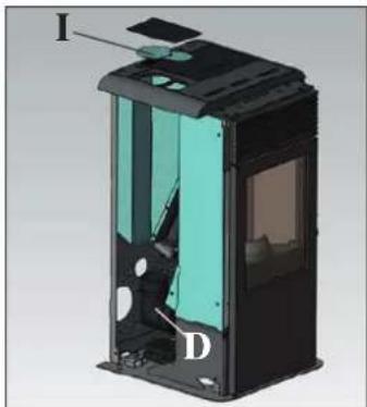
natural_image
3D cutaway view of a device showing internal components labeled I and D (no text or symbols beyond labels)natural_image
3D rendering of a black industrial device with internal structure and ventilation duct (no text or symbols visible)ΣΥΝΑΡΜΟΛΟΓΗΣΗ
ΕΠΕΝΔΥΣΗΣ
natural_image
3D mechanical assembly diagram showing a red component with labeled parts (E, F) and a base plate, no readable text or symbols beyond labels.natural_image
3D model of a red and black electronic device with ventilation grilles and a star-shaped component above it (no text or symbols visible)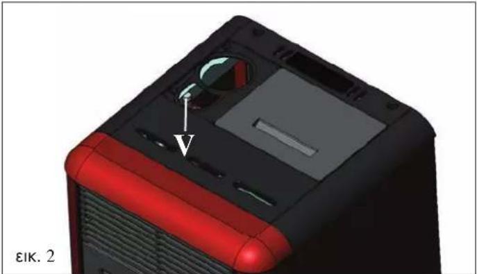
natural_image
3D model of a computer case with red and black casing, showing internal components and a directional arrow (no text or symbols)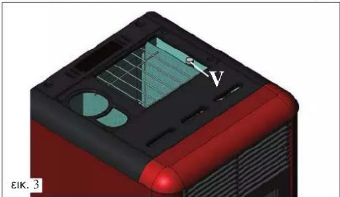
natural_image
3D model of a red and black device casing with internal components and a labeled point V (no text or symbols beyond label)
natural_image
3D rendering of a mechanical device with a labeled component (1) and no visible text or symbols on the main structure.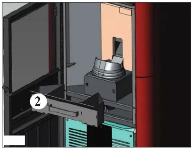
natural_image
3D rendering of a mechanical assembly inside a red-collared cabinet, showing internal components and no visible text or symbols.natural_image
3D rendering of a red industrial machine with a cylindrical component inside, showing internal components and a numbered label (3) on the door.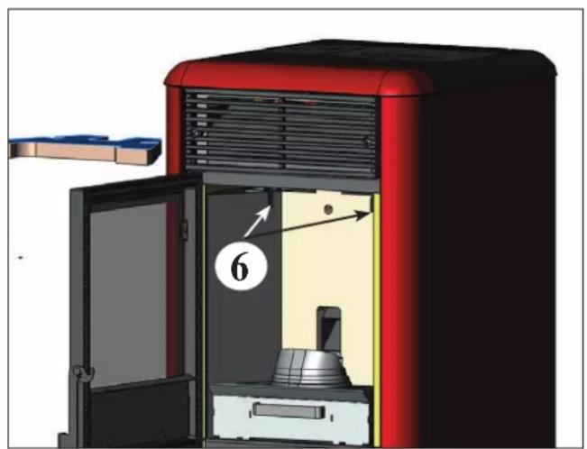
natural_image
3D diagram of a red industrial machine with labeled components and directional arrows (no text or symbols beyond numbers)εικ. C εικ. D
ΣΥΝΤΗΡΗΣΗ
natural_image
Interior view of a mechanical device with labeled components A and B, showing internal components without any text or symbols.εικ. 1 εικ. 2
natural_image
3D rendering of a mechanical assembly with a cylindrical component and mounting bracket (no visible text or symbols)A: izolirana jeklena dimna cev
B: najmanjša višina 1,5 m, torej obvezno čez strešno sleme
C-E: zračni priključek zunanjega zraka (prehodni premer najmanj 80 cm²)
D: jeklena dimovodna cev, v obstoječi zidani dimni cevi.
DIMNIK
natural_image
Cross-sectional diagram of a device casing with internal components and ventilation duct (no text or symbols)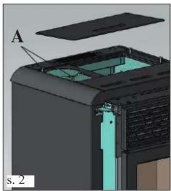
natural_image
3D diagram of a device with labeled component A, showing internal structure and part number 2 (no text or symbols beyond labels)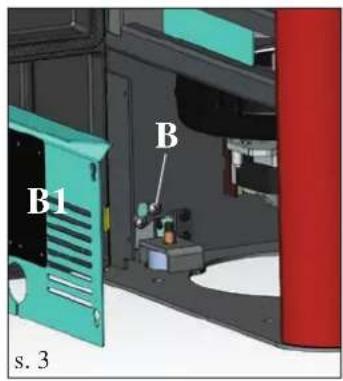
natural_image
3D cutaway view of a device showing internal structure with no visible text or symbols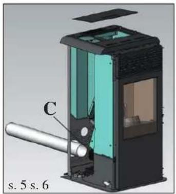
natural_image
Cross-sectional diagram of a device with labeled component C, showing internal structure and no readable text or symbols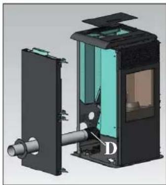
natural_image
3D mechanical assembly diagram showing internal components with no visible text or symbols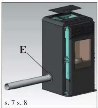
natural_image
3D diagram of a device with labeled component E and part number s.7 s.8 (no text or symbols on the object itself)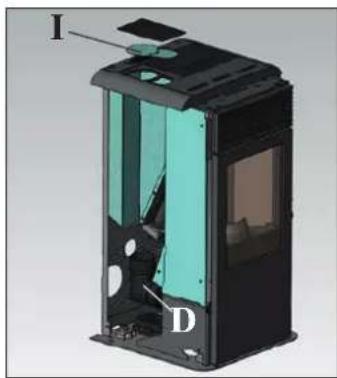
natural_image
Cross-sectional diagram of a device showing internal components labeled I and D (no text or symbols beyond labels)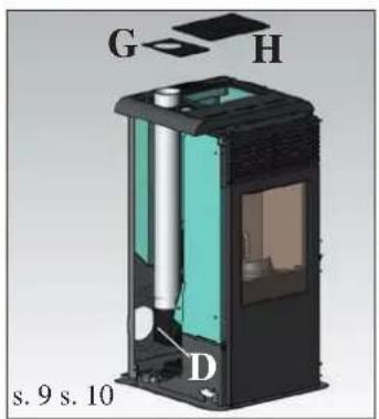
natural_image
3D rendering of a black industrial device with a cylindrical top and internal green compartment, shown without any text or symbols.ODVOD DIMNIH PLINOV
IDROPOINT je izdelana za priklop cevi odvoda dimnih plinov na zgornji, bočni in zadnji strani.
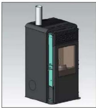
Dobavljena termopeč je nastavljena s priklopo za odvod na zadnji strani (s. 1).
PREDEN PRIKLOPITE ODVOD DIMNIH PLINOV SNE- MITE USTREZNO KOVINSKO STRANICO LEVO.
Priklope izvedite tako:
- Odvijte (za približno 15 mm) oba vijaka na litoželeznem pokrovu pod kovinskim delom (A - s.2).
-Odprite vratca in snemite pocinkano ploščo (B1 - g.3)
natural_image
3D mechanical assembly diagram showing internal components labeled E, F, and F', with no readable text or symbols beyond labelsHIDRA VLIČNI PRIKLJUČKI
NADZOR NAD TEMPERTATURO POVRATNE VODE
Potrebno je vgraditi ustrezen sistem, ki zagotavlja, da je temperatura povratne vode najmanj 45°C.
OPOMBA
natural_image
3D model of a red and black electronic device casing with ventilation grilles and a transparent lid (no text or symbols visible)
natural_image
3D model of a red and black computer case with a dial indicator and arrow pointing to a component (no text or symbols visible)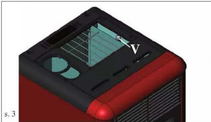
natural_image
3D model of a red and black device casing with internal components, no visible text or symbolsOPOMBA: gorivo
IDROPOINT e izdelana in programirana za zgorevanje lesnih pelet s presekom 6 mm.

gumb za nastavitev želene temperature prostora (AIS) in za dostop k meniju

gumb za nastavitev temperature vode (H2O)

NAPRAVA NA DALJINKSO UPRAVLJANJE
LEGENDA SIMBOLOV
natural_image
3D rendering of a mechanical device with a labeled component (1) and open door, no visible text or symbols beyond the label.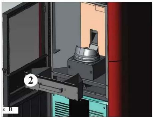
natural_image
3D rendering of a mechanical device inside a transparent enclosure, showing internal components and no visible text or symbolsTEDENSKO VZDRŽEVANJE
- Odstranite zgornjo oblogo (3 - s. C), stresite omela (6 - s. D) in iz predala za pepel odstranite pepel (2 - s. B).
- Izpraznite popolnoma zalogovnik s peleti in posesajte tudi dno.
natural_image
3D rendering of a red industrial machine with a cylindrical component inside, showing internal components and a labeled part (3), no text or symbols present.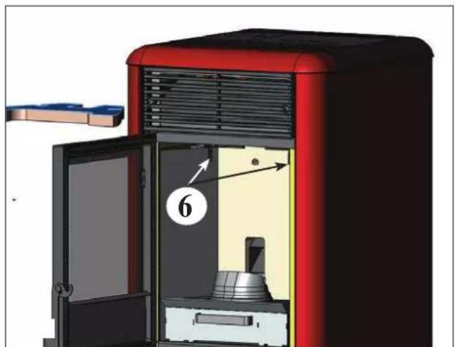
natural_image
3D diagram of a red industrial oven with labeled components and airflow direction arrow (no text or symbols beyond labels)VZDRŽEVANJE
SEZONSKO VZDRŽEVANJE (izvaja CTP)
Zajema:
natural_image
3D rendering of a mechanical assembly with a cylindrical component mounted inside a housing (no visible text or symbols)NASVETI ZA ODPRAVO MOREBITNIH NAPAK
INFORMATIONS POUR LA SÉCURITÉ
IDROPOINT NON DEVE MAI FUNZIONARE SENZA ACIDROPOINT NE DOIT JAMAIS FONCTIONNER AVEC UNE INSTALLATION SANS EAU.
UN ÉVENTUEL ALLUMAGE «A SEC »POURRAIT COM- PROMETTRE LE FONCTIONNEMENT DU THERMOPOÈLE.
IDROPOINT DOIT FONCTIONNER AVEC UNE PRES- SION D'ENVIRON 1,5 BAR.
natural_image
Cross-sectional diagram of a device housing with internal components and an arrow indicating direction (no text or symbols)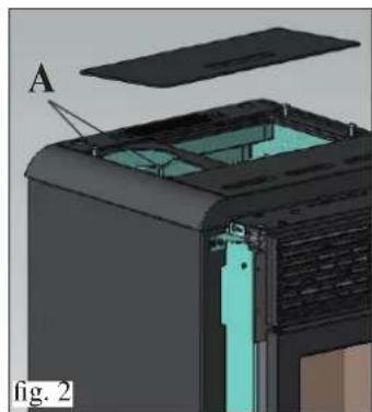
natural_image
3D cutaway view of a device showing internal components and a labeled section (A), no readable text or symbols present.SORTIE DES FUMÉES
natural_image
3D cutaway diagram of a device showing internal components and housing (no text or symbols)natural_image
Cross-sectional diagram of a device with labeled component C, showing internal structure and housing (no text or symbols beyond labels)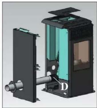
natural_image
3D cutaway view of a mechanical device showing internal components and housing (no text or symbols visible)RACCORDEMENT SORTIE FUMÉES PAR L'ARRIÈRE
natural_image
3D diagram of a device with labeled component E, showing internal structure and shaft (no text or symbols beyond labels)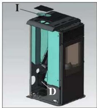
natural_image
3D cutaway view of a device showing internal components labeled I, D, and a highlighted section (no text or symbols beyond labels)RACCORDEMENT SORTIE FUMÉES PAR LE DESSUS
natural_image
3D rendering of a black industrial device with internal structure and ventilation duct (no text or symbols visible)UNE FOIS L'OPÉRATION DE RACCORDEMENT DU TUYAU DE SORTIE DES FUMÉES AU CONDUIT DE CHEMINÉE TERMINÉE, REMONTER LE CÔTÉ EN MÉTAL GAUCHE PUIS POURSUIVRE AVEC L'ASSEMBLAGE DU REVETEMENT (voir page 120).
ASSEMBLAGE

REVÊTEMENT
natural_image
3D mechanical assembly diagram showing a red component with labeled parts E and F, no readable text or symbols beyond labelsRACCORDEMENTS HYDRAULIQUES
(RÉSERVÉ AU CENTRE D'ASSISTANCE TECHNIQUE)
- IDROPOINT NE DOIT JAMAIS FONCTIONNER AVEC L'INSTALLATION SANS EAU.
- LA PRESSION DE FONCTIONNEMENT DOIT ÊTRE DE 1,5 BAR ENVIRON.
- UN ÉVENTUEL ALLUMAGE «A SEC »POURRAIT COMPROMETTRE LE FONCTIONNEMENT DU THERMOPOÊLE.
natural_image
3D model of a red appliance with ventilation grilles and a black plastic cover, showing internal compartments (no text or symbols)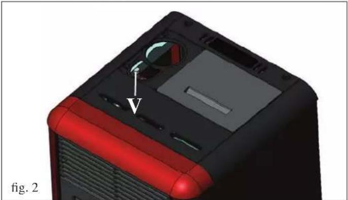
natural_image
3D model of a computer tower with red and black casing, showing internal components and a directional arrow (no text or symbols)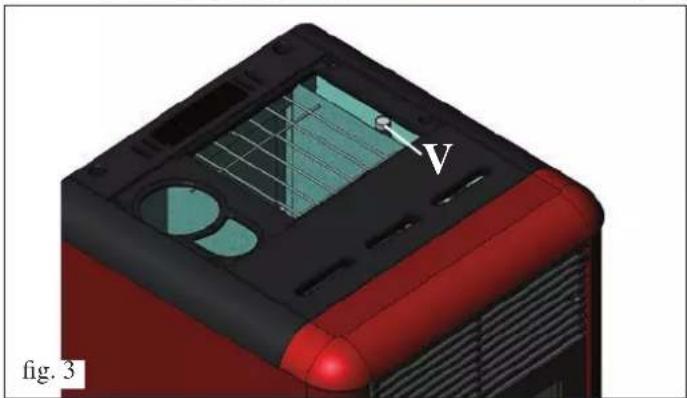
natural_image
3D model of a red and black device casing with internal components and a labeled point V (no text or symbols beyond label)
Programmation Weekend:
natural_image
3D rendering of a mechanical device with a labeled component (1) inside, showing internal components and no visible text or symbols.fig. A
natural_image
3D rendering of a mechanical device inside a storage or processing unit, showing internal components and no visible text or symbols.fig. B
ENTRETIEN HEBDOMADAIRE
natural_image
3D rendering of a red industrial machine with a metallic component and open door, no visible text or symbolsfig. C
natural_image
3D cutaway view of a red industrial machine with labeled component 6 (no text or symbols beyond part number)fig. D
ENTRETIEN
natural_image
Interior view of a mechanical device with labeled components A and B, showing internal components without any text or symbols.fig. 1 fig. 2
natural_image
3D rendering of a mechanical assembly with a cylindrical component mounted on a base, shown in an open enclosure (no text or symbols visible)CONSEILS EN CAS D'ÉVENTUELS INCONVÉNIENTS
SICHERHEITSHINWEISE
IDROPOINT DARF NUR MIT WASSER IN DER ANLAGE BETRIEBEN WERDEN.
BEI ETWAIGEM TROCKENBETRIEB KANN DER OFEN BESCHÄDIGT WERDEN.
DER BETRIEBSDRUCK VON IDROPOINT MUSS CA. 1,5 BAR BETRAGEN.
Differential-Druckmesser
natural_image
Cross-sectional diagram of a device housing with internal components and an arrow indicating direction (no text or symbols)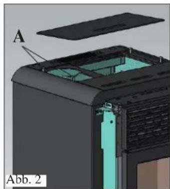
natural_image
3D cutaway view of a device showing internal components and a labeled section (A), no readable text or symbols present.RAUCHABZUG
natural_image
3D cutaway view of a device showing internal components and labeled parts (no text or symbols beyond label)natural_image
3D cutaway view of a mechanical device with internal components and labeled part D (no text or symbols beyond label)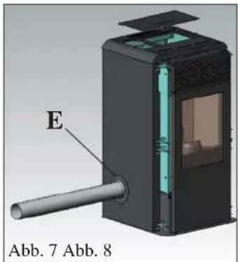
natural_image
3D diagram of a device with labeled component E, showing internal structure and external housing (no text or symbols beyond labels)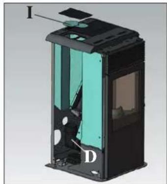
natural_image
3D cutaway view of a device showing internal components labeled I, D, and D (no text or symbols beyond labels)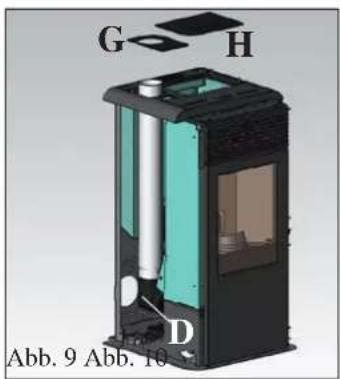
natural_image
3D rendering of a black industrial device with internal structure and ventilation duct (no text or symbols visible)MONTAGE

VERKLEIDUNG
natural_image
3D model of a red and black electronic device casing with ventilation grilles and a plastic cover (no text or symbols visible)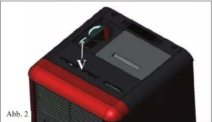
natural_image
3D model of a computer tower with red and black casing, showing internal components and a labeled component (no text or symbols beyond label)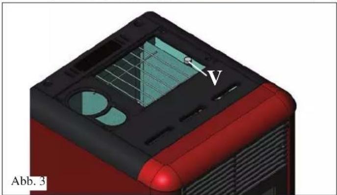
natural_image
3D model of a red and black device casing with internal components, labeled Abb. 3 (no readable text or symbols beyond label)
natural_image
3D rendering of a mechanical device with a labeled component (1) inside, showing internal components and no visible text or symbols.Abb. A
natural_image
3D rendering of a mechanical device inside a room with red walls and a door, no visible text or symbolsAbb. B
natural_image
3D rendering of a red industrial machine with a metallic bucket and open door, no visible text or symbolsAbb. C
natural_image
3D rendering of a red industrial oven with labeled components and airflow direction arrow (no text or symbols beyond labels)Abb. D
WARTUNG
natural_image
3D CAD rendering of a mechanical assembly with a cylindrical component and mounting bracket (no visible text or symbols)TROUBLE SHOOTING
INFORMACJE DOTYCZĄCE BEZPIECZEŃSTWA
PIECYK NIE MOŻE FUNKCJONOWAĆ BEZ WODY W INSTALACJI. EWENTUALNE ROZPALENIE PIECYKA „NA SUCHO” SPOWODUJE USZKODZENIE URŻADZENIA. PIECYK MUSI DZIAŁAC POD CISNIENIEM OKOŁO 1,5 BAR.
natural_image
Cross-sectional diagram of a mechanical device with internal components and labeled 'Rys. 1' (no text or symbols beyond label)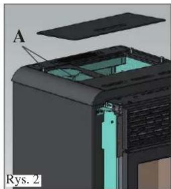
natural_image
3D cutaway view of a mechanical device showing internal components and part A, labeled 'Rys. 2' (no text or symbols on the diagram itself)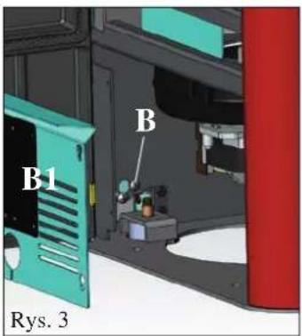

natural_image
3D cutaway view of a device showing internal components and labeled 'Rys. 4' (no text or symbols on the diagram itself)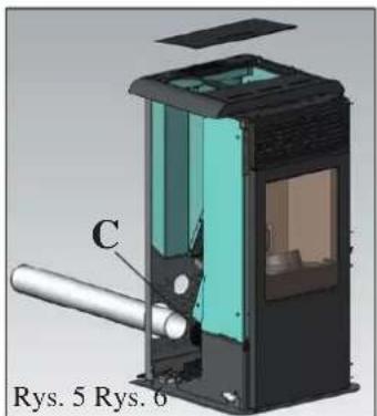
natural_image
3D cutaway diagram of a mechanical device showing internal components and housing (no text or symbols)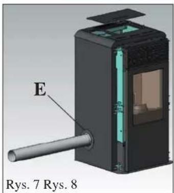
natural_image
3D diagram of a device with labeled component E, showing internal structure and external housing (no text or symbols beyond labels)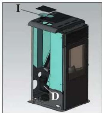
natural_image
3D cutaway view of a device showing internal components labeled I, D, and D (no text or symbols beyond labels)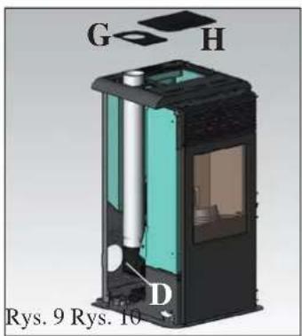
natural_image
3D rendering of a black industrial device with internal structure and ventilation duct (no text or symbols visible)ODPROWADZENIE SPALIN
OBUDOWA
natural_image
3D mechanical assembly diagram showing a red component with labeled parts E, F, and F', no readable text or symbols beyond labelsflowchart
graph TD
    A["TC"] --> B["VA"]
    A --> C["P"]
    A --> D["V"]
    A --> E["V"]
    A --> F["Vec"]
    A --> G["VBP"]
    A --> H["S"]
    I["Kolektor"] --> J["MC"]
    I --> K["MC"]
    I --> L["MC"]
    I --> M["MC"]
    I --> N["MC"]
    I --> O["MC"]
    I --> P["MC"]
    I --> Q["MC"]
    I --> R["MC"]
    I --> S["MC"]
    I --> T["MC"]
    I --> U["MC"]
    I --> V["MC"]
    I --> W["MC"]
    I --> X["MC"]
    I --> Y["MC"]
    I --> Z["MC"]
    I --> AA["MC"]
    I --> AB["MC"]
    I --> AC["MC"]
    I --> AD["MC"]
    I --> AE["MC"]
    I --> AF["MC"]
    I --> AG["MC"]
    I --> AH["MC"]
    I --> AI["MC"]
    I --> AJ["MC"]
    I --> AK["MC"]
    I --> AL["MC"]
    I --> AM["MC"]
    I --> AN["MC"]
    I --> AO["MC"]
    I --> AP["MC"]
    I --> AQ["MC"]
    I --> AR["MC"]
    I --> AS["MC"]
    I --> AT["MC"]
    I --> AU["MC"]
    I --> AV["MC"]
    I --> AW["MC"]
    I --> AX["MC"]
    I --> AY["MC"]
    I --> AZ["MC"]
    I --> BA["MC"]
    I --> BB["MC"]
    I --> BC["MC"]
    I --> BD["MC"]
    I --> BE["MC"]
    I --> BF["MC"]
    I --> BG["MC"]
    I --> BH["MC"]
    I --> BI["MC"]
    I --> BJ["MC"]
    I --> BK["MC"]
    I --> BL["MC"]
    I --> BM["MC"]
    I --> BN["MC"]
    I --> BO["MC"]
    I --> BP["MC"]
    I --> BQ["MC"]
    I --> BR["MC"]
    I --> BS["MC"]
    I --> BT["MC"]
    I --> BU["MC"]
    I --> BV["MC"]
    I --> BW["MC"]
    I --> BX["MC"]
    I --> BY["MC"]
    I --> BZ["MC"]
    I --> CA["MC"]
    I --> CB["MC"]
    I --> CC["MC"]
    I --> CD["MC"]
    I --> CE["MC"]
    I --> CF["MC"]
    I --> CG["MC"]
    I --> CH["MC"]
    I --> CI["MC"]
    I --> CJ["MC"]
    I --> CK["MC"]
    I --> CL["MC"]
    I --> CM["MC"]
    I --> CN["MC"]
    I --> CO["MC"]
    I --> CP["MC"]
    I --> CQ["MC"]
    I --> CR["MC"]
    I --> CS["MC"]
    I --> CT["MC"]
    I --> CU["MC"]
    I --> CV["MC"]
    I --> CW["MC"]
    I --> CX["MC"]
    I --> CY["MC"]
    I --> CZ["MC"]
LEGENDA
natural_image
3D model of a red and black electronic device casing with ventilation grilles and a star-shaped component above it (no text or symbols)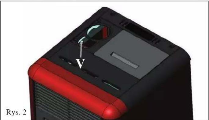
natural_image
3D model of a red and black computer case with a labeled component (no text or symbols on the object itself)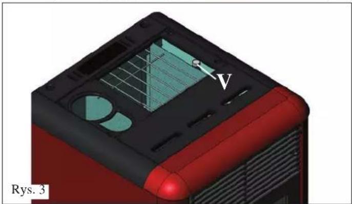
natural_image
3D model of a red and black device casing with internal grid structure and labeled point V (no text or symbols beyond labels)
M2-2 Programator Dzienny
natural_image
3D rendering of a mechanical device with a labeled component (1) inside, showing internal components and no visible text or symbols.Rys. A
natural_image
3D rendering of a mechanical device inside a storage unit with red pipes and a labeled component (no text or symbols visible)Rys. B
KONSERWACJA COTYGODNIOWA
natural_image
3D rendering of a red industrial machine with a metallic component inside, showing internal components and a numbered label (3) on the door.Rys. C
natural_image
3D diagram of a red industrial oven with labeled components and airflow direction arrow (no text or symbols beyond labels)Rys. D
-172 - 172 -
KONSERWACJA
natural_image
3D rendering of a mechanical assembly with a cylindrical component mounted on a base, shown in an open enclosure (no text or symbols visible)POSTĘPOWANIE W PRZYPADKU NIEPRAWIDŁOWOŚCI
OPLYSNINGER VEDR∅RENDE SIKKERHE- DEN
IDROPOINT MÅ ALDRIG ANVENDES UDEN VAND I ANLÆGGET.
EN EVENTUEL T∅ROPTÆNDING KAN KOMPROMITTE- RE BRÆNDEOVNEN.
IDROPOINT SKAL K∅RE MED ET TRYK PÅ CIRKA 1,5 BAR.
natural_image
Cross-sectional diagram of a device casing with internal components and an arrow indicating direction (no text or symbols)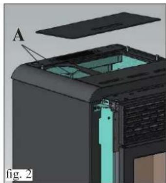
natural_image
3D cutaway view of a device showing internal components and a labeled section (A), no readable text or symbols present.R∅GUDGANG
natural_image
3D cutaway diagram of a device showing internal components and housing (no text or symbols)natural_image
Cross-sectional diagram of a device with labeled component C, showing internal structure and housing (no text or symbols beyond labels)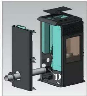
natural_image
3D cutaway view of a mechanical device showing internal components and housing (no text or symbols)TILSLUTNING AF R∅GUDGANG FRA BAGSIDEN
natural_image
3D diagram of a device with labeled component E, shown in two views (Fig. 7 and Fig. 8), no readable text or symbols beyond labels.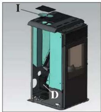
natural_image
3D cutaway view of a device showing internal components labeled I, D, and a highlighted section (no text or symbols beyond labels)NÅR TILSLUTNINGEN AF R∅GUDLEDNINGSR∅-RET TIL SKORSTENSR∅RET ER FÆRDIG, SKAL DU GENMONTERE DEN VENSTRE METALSIDE OG DEREFTER FORTSÆTTE MED MONTERINGEN AF BEKLÆDNINGEN (se side 186).

natural_image
3D rendering of a black industrial device with internal structure and ventilation duct (no text or symbols visible)SAMLING
BEKLÆDNING
natural_image
3D mechanical assembly diagram showing a red cylindrical component with labeled parts (E, F) and a base panel, no readable text or symbols beyond labels.(RESERVERET FOR TEKNISK SERVICECENTER)
- IDROPOINT MÅ ALDRIG ANVENDES UDEN VAND I ANLÆGGET.
- DRIFTSTRYKKET SKAL VÆRE CA. 1,5 BAR.
- EN EVENTUEL T∅ROPTÆNDING KAN KOMPROMITTERE BRÆNDEOVNEN.
BEHANDLING AF VANDET
P: Pumpe (cirkulator)
RA: Varmeapparater
RI: Returanlæg
S: Udtømning
ST: Temperaturføler
TC: Brændevn
V: Kugleventil
VA: Automatisk ventil for luftudtømning
Vec: Lukket ekspansionsbeholder
P: Pumpe (cirkulator)
RA: Varmeapparater
RI: Returanlæg
S: Udtømning
SB: Vandvarmer
ST: Temperaturföler
TC: Brændeovn
V: Kugleventil
VA: Automatisk ventil for luftudtømning
Vec: Lukket ekspansionsbeholder
P: Pumpe (cirkulator)
RA: Varmeapparater
RI: Returanlæg
S: Udtømning
TC: Brændeovn
V: Kugleventil
Vec: Lukket ekspansionsbeholder
PÄFYLDNING AF PILLER I BEHOLDEREN
natural_image
3D model of a red and black electronic device casing with ventilation grilles and a star-shaped component above it (no text or symbols)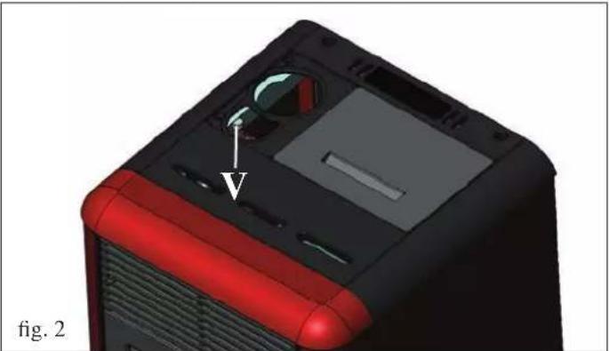
natural_image
3D model of a computer tower with red and black casing, showing internal components and a labeled component (V), no text or symbols present.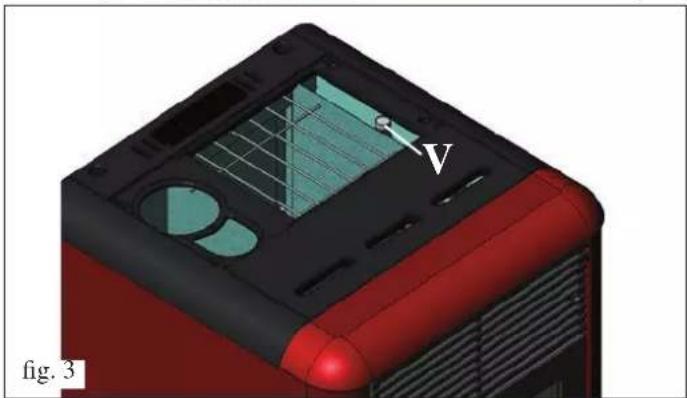
natural_image
3D model of a red and black electronic device casing with visible internal components and a labeled point 'V' (no text or symbols beyond label)
natural_image
3D rendering of a mechanical device with a labeled component (1) inside, showing internal components and no visible text or symbols.fig. A
natural_image
3D rendering of a mechanical device inside a storage or processing unit, showing internal components and no visible text or symbols.fig. B
UGENTLIG VEDLIGEHOLDELSE
natural_image
3D rendering of a red industrial machine with a labeled component (no text or symbols visible)fig. C
natural_image
3D diagram of a red industrial oven with labeled components and airflow direction arrow (no text or symbols beyond labels)fig. D
VEDLIGEHOLDELSE
natural_image
3D CAD model of a mechanical assembly with a cylindrical component and mounting bracket (no visible text or symbols)GODE RÅD FOR EVENTUELLE PROBLEMER
Thank you buying one of our products and congratulations.
Before you start using it, we suggest you read this technical information sheet carefully: it will help you get the best use out of the product and ensure that you always use it in complete safety.
For any further information or requirements, please contact the DEALER where you bought the product or visit our website www.edilkamin.com and see the DEALERS section.
NOTE
- After removing the product from the packaging, check that the contents are intact and complete (remote control, elbow joint complete with band, rosette, 2 steel half-covers, "cold-hand" handle, casing, guarantee booklet, glove, technical information sheet, spatula, dehumidifying salts).
In the case of anomaly, please contact the dealer where you bought the product immediately, presenting a copy of the guarantee booklet and the official purchase receipt or invoice.
- Starting up/testing
This must be carried out by an EDILKAMIN authorised Technical Assistance Centre (TAC) otherwise the guarantee shall not be effective. The start-up as described by standard UNI 10683 consists of a series of checks carried out when the stove is completely installed to ensure the correct functioning of the system and compliance with standards.
The nearest Assistance Centre can be found by telephoning the toll-free number or by visiting the site www.edilkamin.com.
- the manufacturer shall accept no liability whatsoever from any damage deriving from use in the case of incorrect installation, incorrect maintenance or incorrect use of the product.
- the warranty number necessary for identifying the stove, is indicated:
- on the upper part of the packaging
- in the guarantee booklet placed inside the combustion chamber
- on the plate affixed to the rear part of the product;
This documentation must be kept for identification, together with the official purchase receipt or invoice. This data must be given when you ask for information and must be made available in the case of any maintenance work;
- the details presented are graphically and geometrically indicative.
The undersigned EDILKAMIN S.p.A. with registered head office at Via Vincenzo Monti 47 - 20123 Milan - Italy - tax code and VAT no. 00192220192
The pellet stove illustrated below conforms to Regulation EU 305/2011 (CPR) and to the harmonised European Standard EN 14785:2006
The PELLET stove bearing the trademark ITALIANA CAMINI, specifically named IDROPOINT
Year of manufacture: Ref. Data nameplate Declaration of performance (DoP - EK 102): Ref. data tag plate
It is also declared that:
the wood pellet burning stove IDROPOINT complies with the requirements of the European directives:
2006/95/EEC - Low voltage directive
2004/108/EEC - Electromagnetic compatibility directive
EDILKAMIN S.p.A. declines all responsibility for the malfunctioning of a product in the case of replacement, assembly and/or modifications not carried out EDILKAMIN personnel and without the latter's authorisation.
OPERATING PRINCIPLE
The fuel (pellets) is taken from the hopper (A) and, using a screw (B) operated by a gear motor (C), is sent to the crucible (D).
The pellets are lit by hot air produced by an electrical element (E) sucked into the crucible through a smoke extractor fan (F).
The smoke produced by combustion is extracted from the combustion chamber by the same fan (F) and expelled from the vent (G) which can be connected to the back, the left side or the top of the stove (see page 207).
The combustion chamber, with base and ceiling in Vermiculite, closed at the front by a door in ceramic glass (special "cold-hand" handle to open the door).
The water in the boiler is heated and sent by the built-in pump (H) to the heating system.
The stove has a closed expansion tank (I) and a built-in pressure safety valve (L).
The quantity of fuel, the extraction of the smoke and the input of air for combustion are regulated by a motherboard equipped with software, to obtain a high combustion yield and low emissions.
The stove has a serial socket for optional wire connection (code 640560) to remote controlled ignition devices (chrono-thermostats etc.).
The ceramic outer casing is available in three colour variants: cream, burgundy and grey.

SAFETY INFORMATION
IDROPOINT MUST NEVER OPERATE WITHOUT WATER IN THE SYSTEM.
SWITCHING ON WHEN "DRY" CAN DAMAGE THE STOVE.
IDROPOINT MUST OPERATE WITH A PRESSURE OF ABOUT 1.5 BARS.
- The only risks deriving from the use of the stove are linked to not respecting the installation rules, direct contact with live electrical parts (internal parts), contact with flames or hot parts (glass, pipes, hot air output) or to the introduction of foreign substances.
- If any component does not function correctly, the stove has safety devices which guarantee that it will switch off; in such cases, allow the stove to switch itself off without intervening.
- To function correctly, the stove must be installed according to the indications given on this sheet and the door must not be opened during operation: combustion is managed automatically, no action is necessary.
- For fuel, use only wood pellets with a diameter of 6 mm.
- Under no circumstances may foreign substances be placed in the combustion chamber or the pellet hopper.
- The flue (the duct connecting the smoke output vent of the stove to the chimney) must not be cleaned with flammable products.
- Do not clean when hot.
- The parts of the combustion chamber and the pellet hopper must be vacuumed only when COLD.
- The glass can be cleaned when it is COLD with a special product applied with a cloth.
- Make sure the stove is installed and switched on for the first time by an Edilkamin authorised TAC (Technical Assistance Centre) according to the indications given on this sheet; otherwise the guarantee will not be valid.
- During operation, the discharge pipes become very hot (do not touch them without the special glove).
- Do not place heat-sensitive objects next to the stove.
- NEVER use flammable liquids to light the stove or to revive hot embers.
- Do not block ventilation into the room where the stove is installed, and do not block the air intake of the stove itself.
- Do not allow the stove to get wet, and do not place wet hands anywhere near the electrical parts.
- Do not insert reductions into the smoke discharge pipes.
- The stove must be installed in a room with an adequate fire-prevention system, and it must also be provided with all systems (input and discharge) required by the stove for safe operation.
- Make sure that the return water temperature is at least 45^-50^ .
- The temperature of the room where the stove is installed must not fall below 0^ .
- If necessary, add antifreeze liquid to the water of the system.
- If the stove does not light, do NOT repeat ignition before having emptied the crucible.
- ATTENTION: PELLETS REMOVED FROM THE CRUCIBLE MUST NOT BE PLACED BACK INTO THE HOPPER.
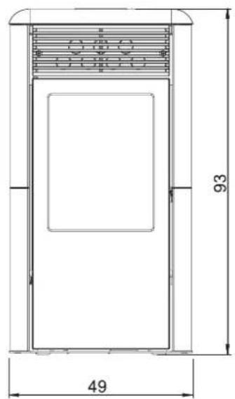
FRONT
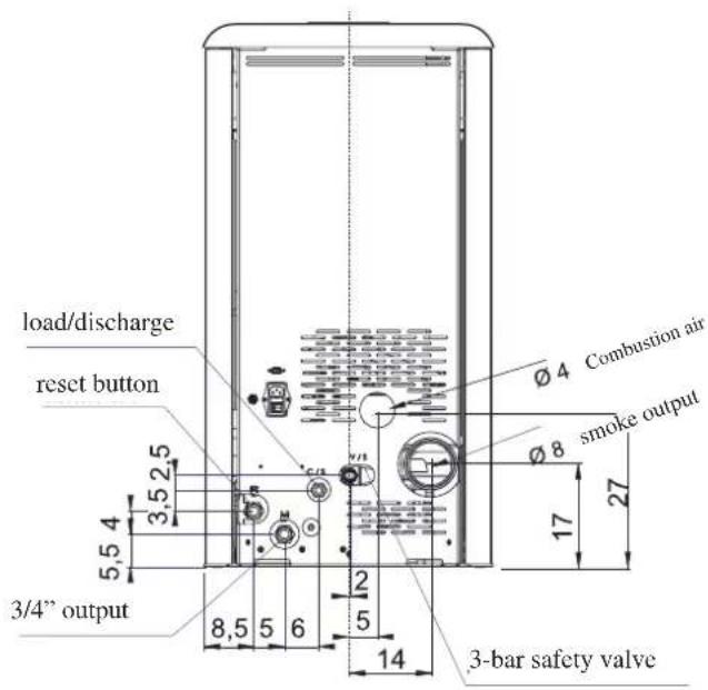
BACK
SIDE
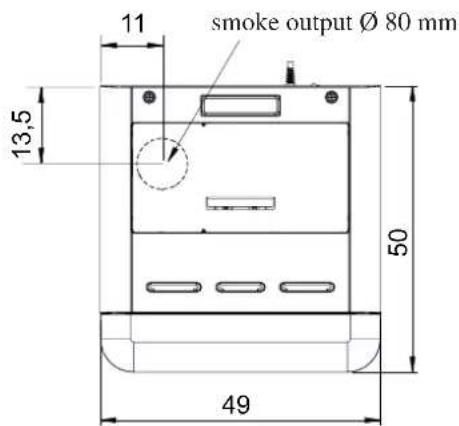
VIEW FROM ABOVE
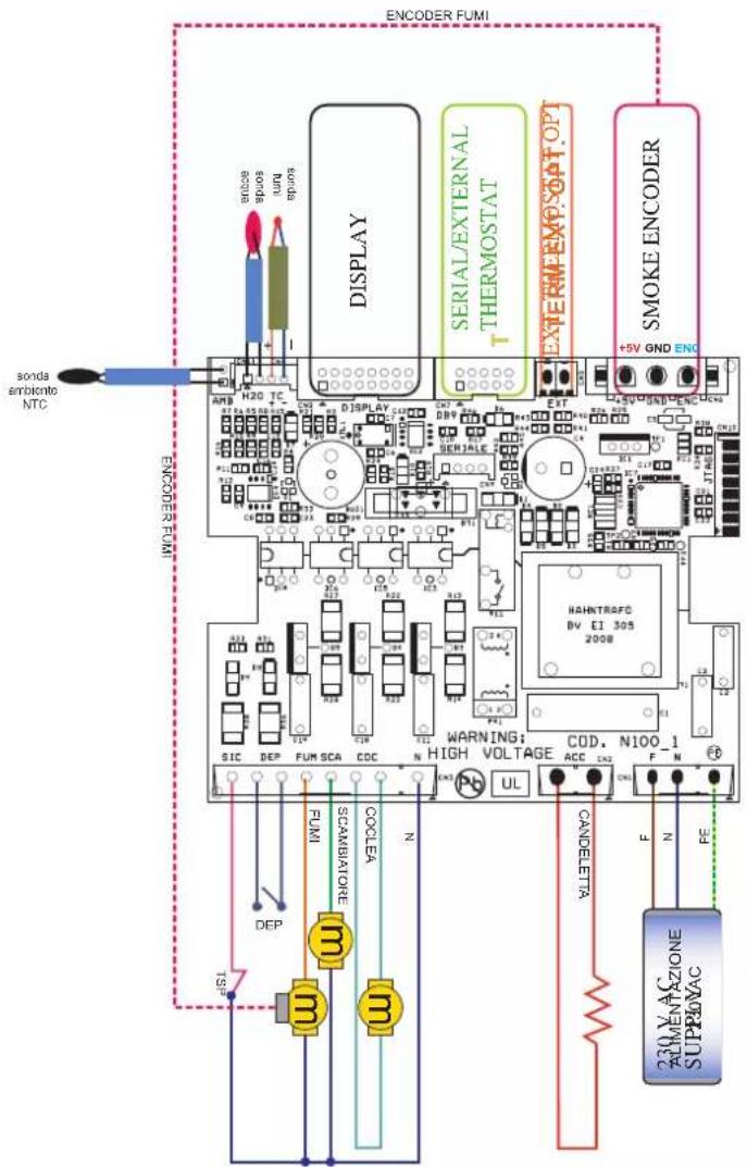
ELECTRONIC APPARATUS
MOTHERBOARD
SERIAL PORT
The stove has a serial port RS232, to which an optional on-off control device, such as an environment thermostat, can be installed by the TAC using a special wire (code 640560).
The serial socket is inside the stove, on the left side.
BACKUP BATTERY
The motherboard has a backup battery (type CR 2032, 3 volts).
Failure of the battery is due to normal wear and tear (and is not a manufacturing defect).
For more information, contact the TAC which carried out the first ignition.
SAFETY DEVICES
• THERMOCOUPLE:
Positioned on the smoke discharge, it measures the temperature.
According to the set parameters, it controls ignition, operation and switching off.
• DIFFERENTIAL PRESSURE SWITCH:
Positioned in the smoke-aspiration area, it is triggered in the case of a depression in the circuit (e.g. obstructed flue).
• SAFETY THERMOSTAT:
This intervenes if the temperature inside the stove is too high.
It blocks pellet loading causing the stove to go out.
• WATER SAFETY THERMOSTAT:
This intervenes if the temperature of the water inside the stove is too high.
It blocks pellet loading causing the stove to go out.
Manually reset using the button on the back of the stove (see page 202).
FEATURES
| THERMO-TECHNICAL FEATURES | ||
| Nominal power 11,5 kW | ||
| Nominal power transferred to the water | 8,3 kW | |
| Approx. global yield 90,1 % | ||
| CO emission (13% O_2 ) 0,013 % | ||
| Max pressure 2 bar | ||
| Operating pressure | 1,5 bar | |
| Smoke output temperature | 140 °C | |
| Minimum draught 12 Pa | ||
| Min/max autonomy | 5 / 18 | hours |
| Min/max fuel consumption | 0,8 / 2,7 | kg/h |
| Pellet hopper capacity | 14 | kg |
| Volume heated * | 300 m^3 | |
| Weight inc. packaging | 142 kg | |
| Diameter of smoke duct (male) | 80 mm | |
| Diameter of air intake duct (male) | 40 mm | |
* The volume which can be heated is calculated assuming insulation pursuant to Italian law 10/91 and successive amendments and a heat requirement of 33 Kcal/m³ hour.
* It is important to also take into consideration the position of the stove in the environment to be heated.
N.B.
1) take into consideration that external appliances can disturb the functioning of the motherboard.
2) attention: operations on live components and/or checks must only be carried out by qualified personnel.
(Before carrying out any maintenance, disconnect the appliance from the mains electricity)
| ELECTRICAL FEATURES | ||
| Power supply 230Vac +/- 10% 50 Hz | ||
| Average power consumption 150 W | ||
| Power consumption during ignition 400 W | ||
| Motherboard protection * Fuse F4 AL, 250 Vac | ||
The above data are indicative.
EDILKAMIN s.p.a. reserves the right to modify the products at its undisputable discretion, without notice.
SAFETY AND MEASURING DEVICES
Smoke thermocouple
Positioned on the smoke discharge, it measures the temperature.
If the temperature is too low, it adjusts the ignition phase, and if the temperature is too high, it will close down stove operation.
Differential pressure switch
This will cause the stove to switch off by interrupting the supply of pellets if the door is opened, if the flue is clogged, if gaskets are too worn, or if the periodical (non-routine) stove cleaning is not carried out.
Screw safety thermostat
Placed near the pellet hopper, this stops the electricity supply to the pellet motor if the temperature is too high.
Water temp. probe
This measures the temperature of the water in the stove, and sends the reading to the information board, which adjusts power to the stove. If the temperature is too high, stove operation is closed down.
Water safety thermostat, with manual reset
This reads the temperature of the water in the stove. If the temperature is too high, it cuts off the electricity supply to the gear motor.
If the thermostat has triggered a reaction, it must be reset by pressing the red button at the back of the stove.
Pressure safety valve
When the pressure indicated on the information plate is reached, this valve causes the water in the system to be discharged, with consequent need for refilling.
ATTENTION!!!! Remember to set up connection to the sewer system.
Pressure meter
Positioned on the back of the stove, the water pressure to be read.
During operation, the recommended pressure is 1 bar.
IF STOVE OPERATION IS STOPPED, THE CAUSE IS SHOWN ON THE DISPLAY AND THE CLOSE-DOWN IS MEMORISED.
COMPONENTS
Resistance
Triggers pellet combustion. It remains on until the pellets actually start to burn.
Smoke extractor fan
“Pushes” the smoke into the flue and the consequent depression causes the intake of combustion air.
Gear motor
Activates the screw allowing the transport of the pellets from the hopper to the crucible.
Pump (circulator)
“Pushes” the water towards the heating system.
Closed expansion tank
“Absorbs” the extra volume of water in the stove due to heating.
A specialist technician must consider whether an extra tank is necessary, according to the total volume of water contained in the system!
Bleed valves:
Positioned in the upper part (see page 211), these allow for any air introduced when the water is loaded into the stove to be bled.
If information is not expressly indicated, please refer to the local standards for your country. In Italy, please refer to the standard UNI 10683, and to any regional or local public-health regulations.
In the case of installation in a multiple-tenancy building, contact the building manager before installation.
CHECK OF COMPATIBILITY WITH OTHER DEVICES
The stove must NOT be installed in the same room as extractor fans, type B heating appliances, or other appliances which can compromise correct operation.
See standard UNI 10683.
CHECK THE ELECTRICAL CONNECTION (the socket must be in an easily accessible position)
The stove is provided with a wire for the electricity supply to be connected to a 230V 50 Hz socket, preferably with a magnetothermal switch. If the electricity socket is not easily accessible, place a switch upstream of the stove (to be provided by the customer).
Voltage variations of more than 10% can damage the stove.
The electricity system must comply with standards; in particular, check the efficiency of the earth circuit.
The diameter of the power supply line must be adequate for the power required by the stove.
An inefficient earth circuit can cause malfunctioning of the stove, for which Edilkamin will accept no responsibility.
FIRE PREVENTION SAFETY DISTANCE
The stove can be positioned directly against a masonry or plasterboard wall.
If the wall is flammable (wood), adequate insulation in non-flammable material must be fitted.
The flue pipe must be adequately insulated, since it reaches high temperatures.
Every object on either side of the stove in flammable and/or heat sensitive material must be kept at least 20 cm from the stove, or it must be suitably insulated with non-flammable insulating material; under no circumstances must any object be placed less than 80 cm from the front of the stove, since it will be directly subjected to the radiation of heat from the combustion chamber.
AIR INTAKE VENT
An air intake vent connected with the external environment must be installed behind the stove; it must have an inner diameter of at least 80 cm^2 to guarantee sufficient air intake for combustion.
SMOKE DISCHARGE
The discharge system must only serve the stove (the smoke must not be discharged into a chimney also used for other stoves/fireplaces etc.).
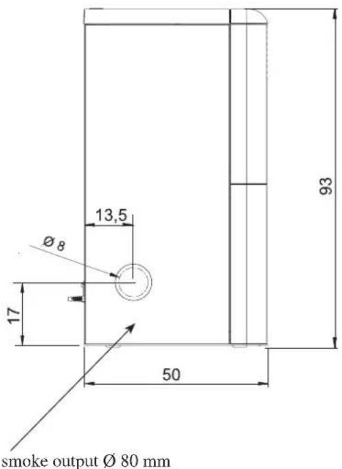
The smoke is discharged through the 8 cm diameter vent positioned on the back, side or top of the stove.
The flue must be connected to the external environment by steel pipes with EN 1856 certification. The pipe must be hermetically sealed.
The pipes must be sealed, and if necessary insulated, with materials resistant to high temperatures (silicon or mastics for high temperatures).
The only horizontal stretch allowed can be 2 m long. There must be no more than two bends, with a maximum angle of 90^ (in relation to the vertical piece).
A vertical stretch and a wind-proof terminal (reference UNI 10683) are required (unless the flue is inserted into a chimney). If the flue runs outside the building, adequate insulation is necessary. If the flue is inserted into a chimney, the chimney must be suitable for solid fuel, and if it is larger than 150 mm, pipes with a suitable diameter and in suitable material (e.g. steel 80 mm) must be fitted inside the chimney.
It must be possible to inspect all sections of the smoke duct. Chimneys and flues to which solid fuel burning appliances are connected must be cleaned at least once a year (check the relative standards in your country).
If they are not checked and cleaned regularly, there is an increased risk of the chimney catching fire. In such a case, do not attempt to put out the fire with water; empty the pellet hopper. Contact specialist personnel before re-igniting the stove.
TYPICAL CASES
Fig. 1 Fig. 2
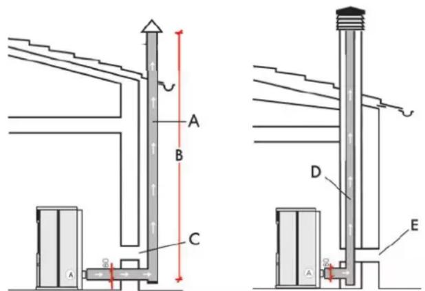
A: flue in insulated steel
B: minimum height 1.5 m and, in any case, above the level of roof guttering
C-E: vent for the intake of air from the external environment (minimum internal diameter 80 cm²)
D: steel flue inserted into an existing masonry chimney
CHIMNEY POT
The basic features are:
- internal section at the base equal to that of the flue
- output section no less than double that of the flue
- position in full wind, above the roof ridge and beyond the reflux area.
INSTALLATION

natural_image
Cross-sectional diagram of a device casing with internal components and an arrow indicating direction (no text or symbols)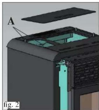
natural_image
3D cutaway view of a device showing internal components and a labeled section (A), no readable text or symbols present.SMOKE OUTPUT
IDROPOINT is designed for the connection of the flue at the top, back or side of the stove.
The stove is delivered ready for the output of the flue from the back (fig. 1).
FOR THE CONNECTION OF THE SMOKE OUTPUT TO THE CHIMNEY, WHETHER FROM THE BACK, SIDE OR TOP, IT IS NECESSARY TO REMOVE THE LEFT SIDE.
natural_image
3D cutaway diagram of a device showing internal components and housing (no text or symbols)To connect:
- Loosen (by about 15 mm) the two screws on the cast iron top under the steel cover (A - fig. 2).
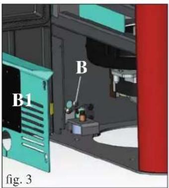
- Open the door and remove the galvanised panel (B1 - fig. 3)
- Loosen the screw on the lower/front part of the right and left sides (B -fig. 3).
- Remove the screw above the top (see fig. 5 on page 208)
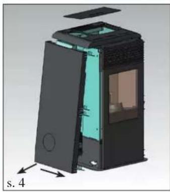
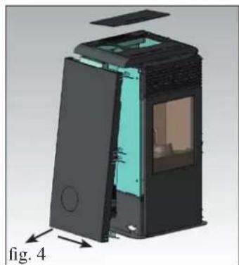
- Remove the metallic left side), moving it about 2 cm towards the front of the stove, extracting it first from below and then pulling it out from under the top (fig. 4).
At this point, choose the necessary flue connection.
REAR SMOKE OUTPUT CONNECTION
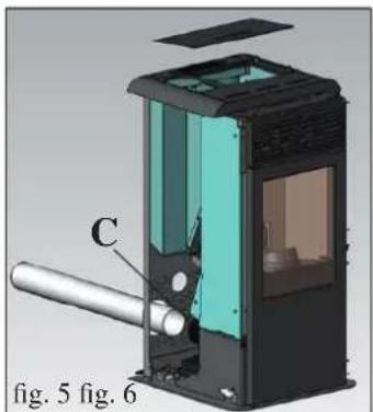
Connect the rear smoke output pipe (not provided) to the smoke extractor unit vent (C- fig. 5) with the band provided. In this case it is sufficient to make the smoke output pipe (not provided) pass through the hole in the lower part of the sheet metal back (fig. 5).
natural_image
Cross-sectional diagram of a mechanical device with labeled component C, shown in 3D view (no text or symbols beyond labels)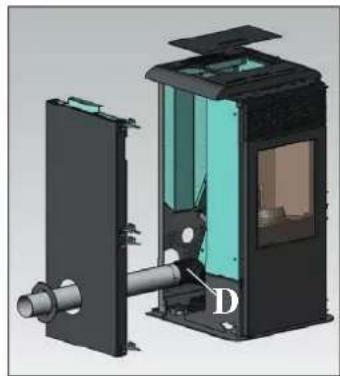
natural_image
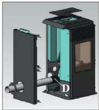
3D cutaway view of a mechanical device showing internal components and housing (no text or symbols)Fit the elbow joint to the smoke extractor unit vent (D- fig. 6) with the band provided.
Connect the side smoke output pipe (not provided) to the aforementioned elbow joint.
Remove the pre-cut diaphragm from the sheet metal side to allow the smoke output pipe (not provided) to pass through (fig. 6).
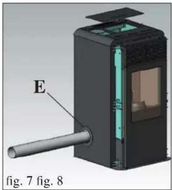
Complete the operation by applying the closure rosette provided (E - fig. 7) using the screws provided, after replacing the metal side.
natural_image
3D diagram of a device with labeled component E, shown in two views (Fig. 7 and Fig. 8), no readable text or symbols beyond labels.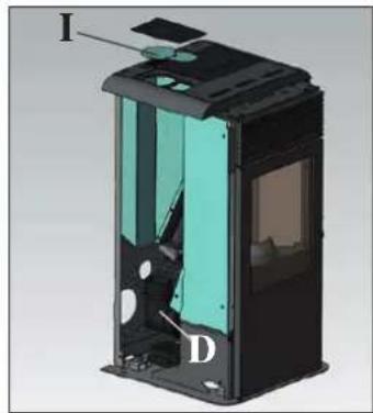
natural_image
3D cutaway view of a device showing internal components labeled I, D, and a highlighted section (no text or symbols beyond labels)N.B. The rosette and the metal side must be fitted after the flue has been definitively fixed.
TOP SMOKE OUTPUT CONNECTION
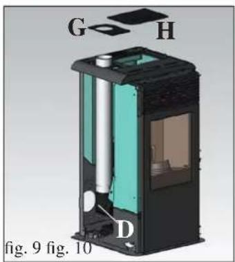
Fit the elbow connection to the smoke extractor unit vent (D-fig. 8) with the band provided.
Connect the smoke output pipe (not provided) to the aforesaid elbow joint.
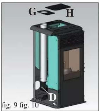
In this case, it is necessary to use the two sheet metal half-covers provided (G - H - fig. 9), instead of the whole sheet metal cover, and to eliminate the galvanised cap (I - fig. 8).
Remove the diaphragm from the small metal half-cover (G - fig.9) to allow passage of the pipe.
natural_image
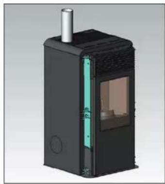
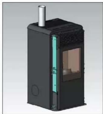
3D rendering of a black industrial device with internal structure and ventilation duct (no text or symbols visible)AFTER COMPLETING THE CONNECTION OF THE SMOKE OUTPUT PIPE TO THE FLUE, REPLACE THE LEFT METAL SIDE AND THEN CONTINUE WITH THE APPLICATION OF THE CASING (see page 208).
ASSEMBLY
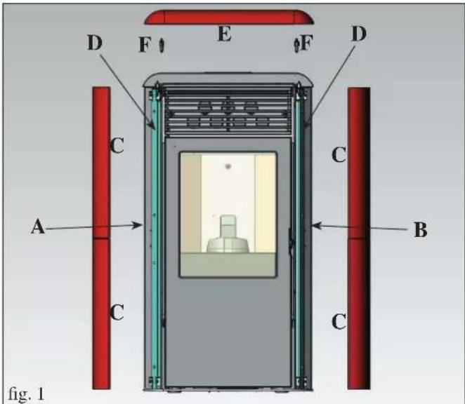
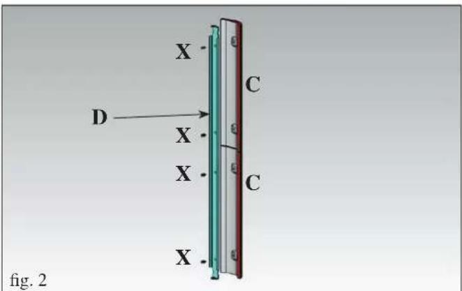
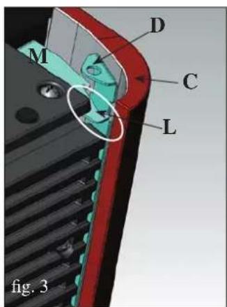
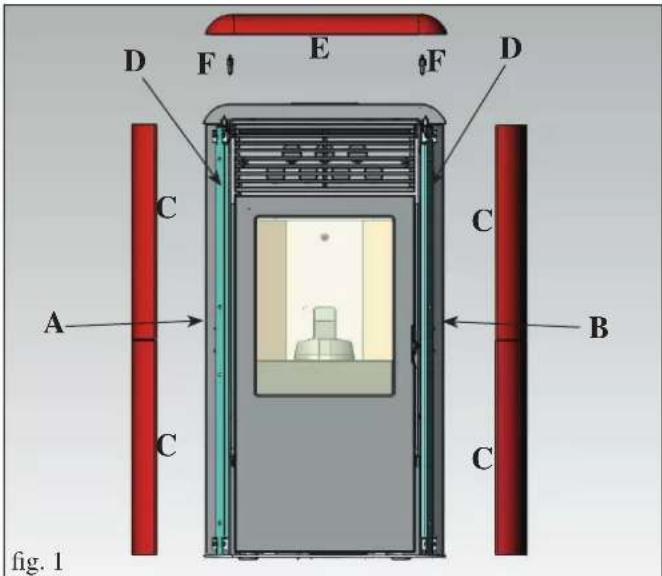
CASING
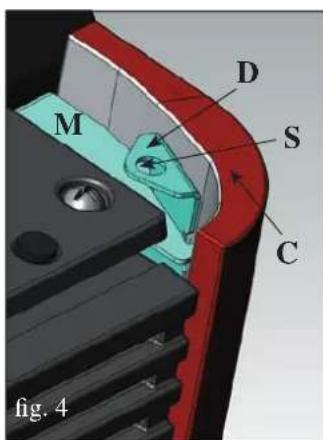
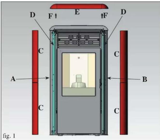
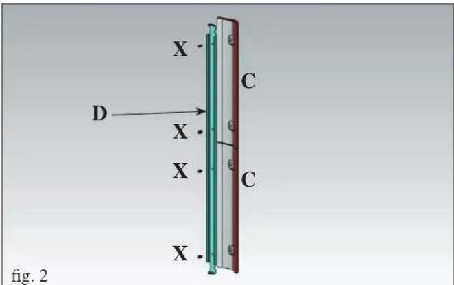
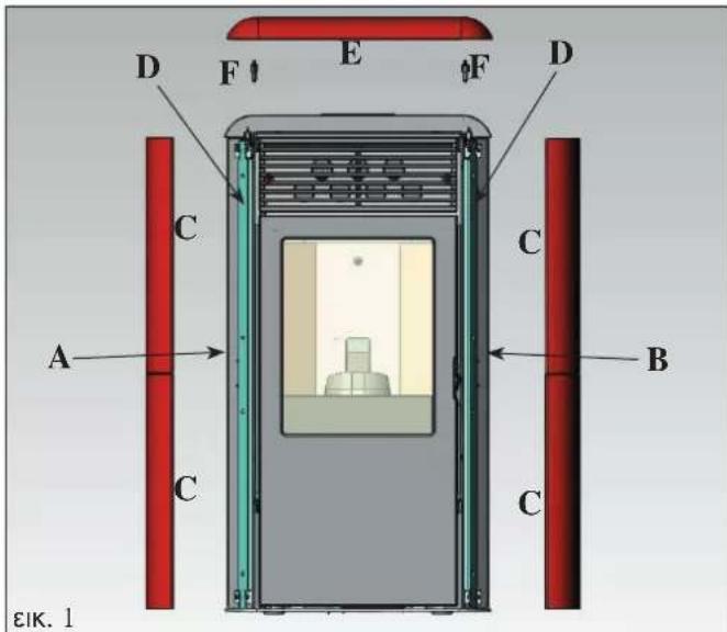
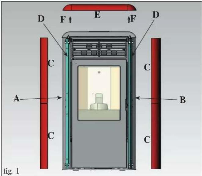
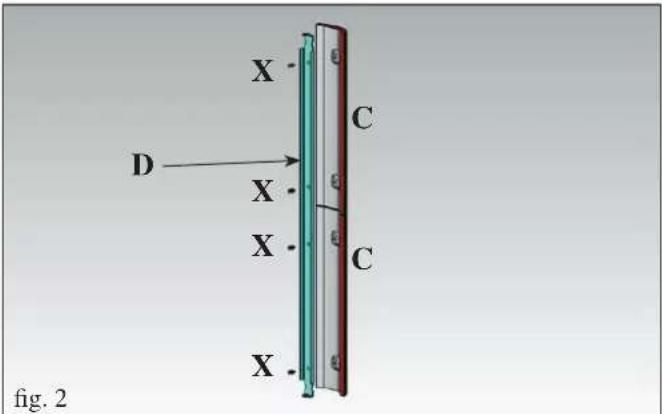
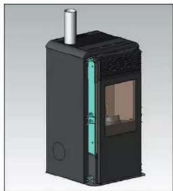
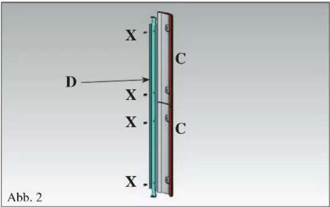
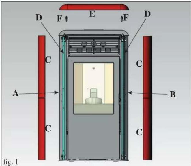
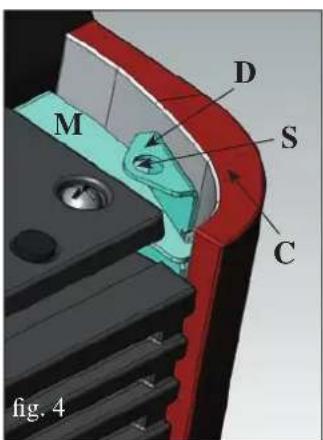
The stove is delivered with metallic sides (A-B) and the metallic brackets for fixing the ceramic side elements (D) already fitted. The pieces indicated below are packaged separately.
• 4 ceramic front side elements (C)
• 1 ceramic top insert (E)
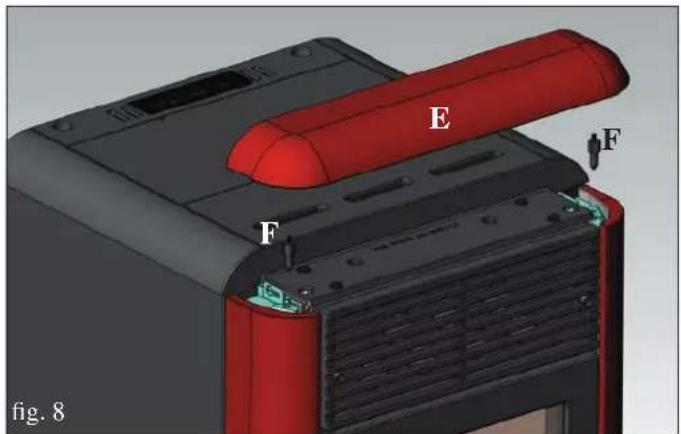
- 2 dowels for the ceramic top insert (F)
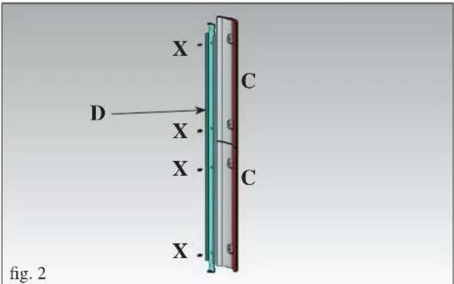
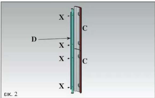
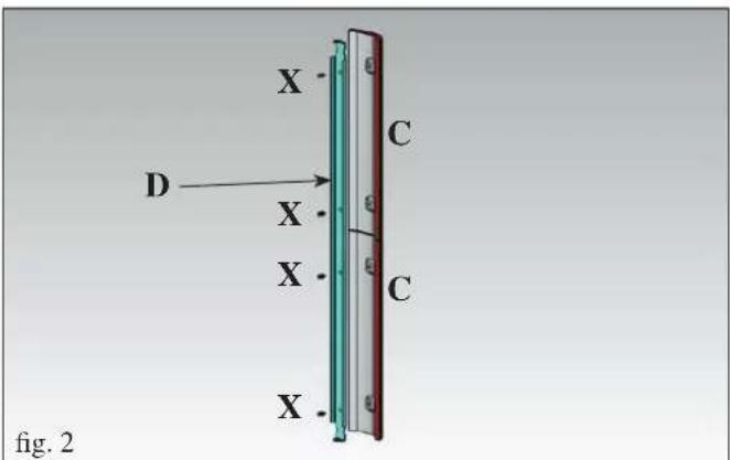
• 8 M4 screws with milled heads (X)
- 8 washers ∅ 4
To fit proceed as follows:
Fig. 1/2/3
Remove the two metallic brackets fixing the stove's ceramic side elements (D) by sliding them from the bottom upwards, about 3 cm. Apply metallic brackets (D) onto the back of the ceramic front side elements (C), fixing them into the holes provided using the M4 screws and the washers ∅ 4 (provided).
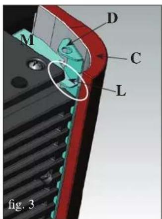
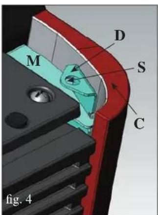
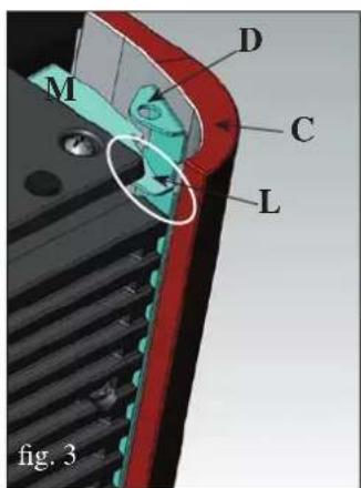
Fig. 3/4
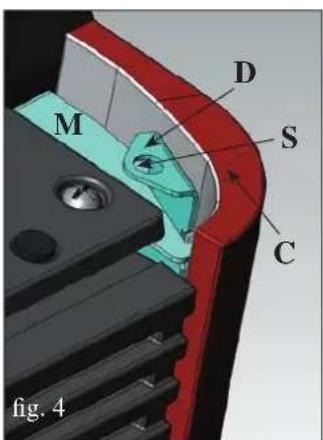
Fit the ceramic sides elements (C) (complete with metallic brackets) from above moving them downwards into the slot (L) on the square elements of the metallic side (M).
Fig. 5/6/7
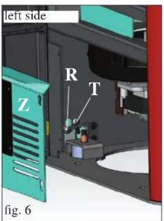
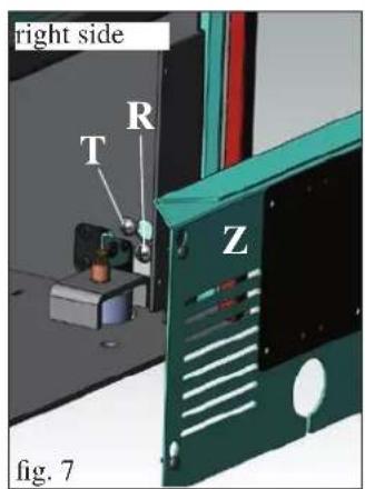
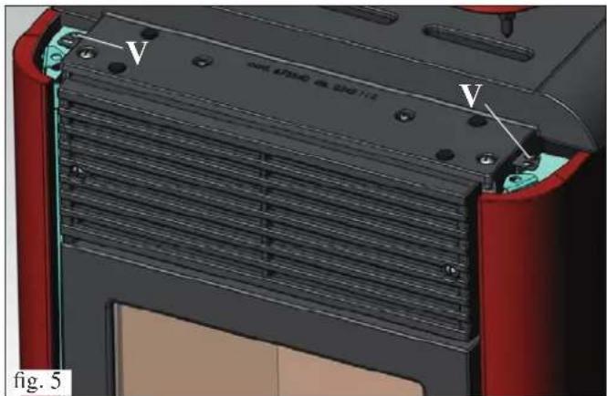
Check the vertical alignment of the ceramic side elements (C) and make any necessary adjustments with the screws above the top (V - fig. 5) and inside the stove with the screws (R - fig. 6/7)
N.B. Before carrying out this operation, remove the galvanised panel (Z - fig. 6/7) on both sides and loosen the locking screws (T - fig. 6/7).
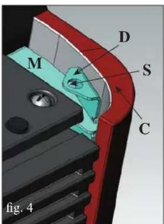
Fig. 4/8
Apply the two dowels (F) onto the lower side of the ceramic top insert (E), screwing them into the holes provided. Position the ceramic top insert, fitting the dowels into the holes (S) provided on the metallic brackets (D) installed previously.
natural_image
3D mechanical assembly diagram showing a red cylindrical component with labeled parts E and F, no readable text or symbols beyond labelsPLUMBING
(FOR TECHNICAL ASSISTANCE CENTRE USE ONLY)
- IDROPOINT MUST NEVER OPERATE WITHOUT WATER IN THE SYSTEM.
- OPERATING PRESSURE MUST BE ABOUT 1.5 BARS.
- SWITCHING ON WHEN "DRY" CAN DAMAGE THE STOVE.
Plumbing must be carried out by qualified personnel and a declaration of conformity must be issued pursuant to Min. Decree 37 ex Law 46/90.
In any case, it is essential that the laws in force in the country concerned are followed.
- For the water input, return and discharge connections, opt for suitable solutions to facilitate, if necessary, a any future re-positioning of the stove.
- For better performance, the primary circuit (where the heat generator is situated) must be separate from the secondary circuit (user).
For example, using a plate exchanger which allows the exchange of energy in the form of heat without mixing the waters.
WATER TREATMENT
It may be necessary to add anti-freeze, anti-scaling and anti-corrosion additives suitable for light alloys.
If the water for filling and topping up the stove has a hardness of above 35^ F, use a water softener.
For suggestions, consult the standard UNI 8065-1989 (Water treatment in heating systems for civil use).
NOTES ON THE RETURN WATER TEMPERATURE
A suitable system which guarantees a return water temperature of no less than 45^ - 50^ is required.
N.B.
- The installer must assess whether an extra expansion tank is necessary, according to the type of system served.
- During the production of domestic hot water, there is a temporary reduction in supply to the radiators.
- FIRST IGNITION
Check that the plumbing is correct and that the expansion tank is sufficient to guarantee safety.
The existence of the tank built into the stove does NOT guarantee adequate protection against the increased volume of the heated water of the whole system.
Switch on the electricity to the stove and carry out testing while cold.
Fill the water circuit using the loading connection (the recommended pressure is about 1.5 bars).
During loading, "bleed" the pump and open the manual bleed valve (see page 211).
This operation must also be repeated periodically.
PLUMBING
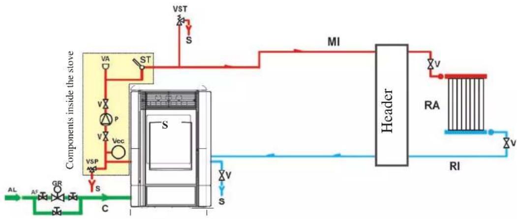
Heating system with the Stove as the only heat source.
This diagram is indicative; correct execution is the responsibility of the plumber.
flowchart
graph TD
    A["AL"] --> B["AF"]
    B --> C["GR"]
    C --> D["C"]
    D --> E["VSP"]
    E --> F["S"]
    F --> G["VA"]
    G --> H["ST"]
    H --> I["S"]
    I --> J["VST"]
    J --> K["S"]
    K --> L["Header"]
    L --> M["V"]
    M --> N["RA"]
    N --> O["V"]
    O --> P["RI"]
    P --> Q["V"]
    Q --> R["S"]
    R --> S["SI"]
    S --> T["MI"]
    T --> U["Header"]
    U --> V["RA"]
    V --> W["V"]
    W --> X["RI"]
    X --> Y["S"]
KEY
CW: Cold water
WS: Water supply
L: Load/refill
PR: Pressure reducer
SO: System output
P: Pump (circulator)
RA: Radiators
SR: System return
D: Discharge
WT: Water temp. probe
S: Stove
BV: Ball valve
AV: Automatic air discharge valve
CET: Closed expansion tank
SV: Safety valve
TDV: Thermal discharge valve
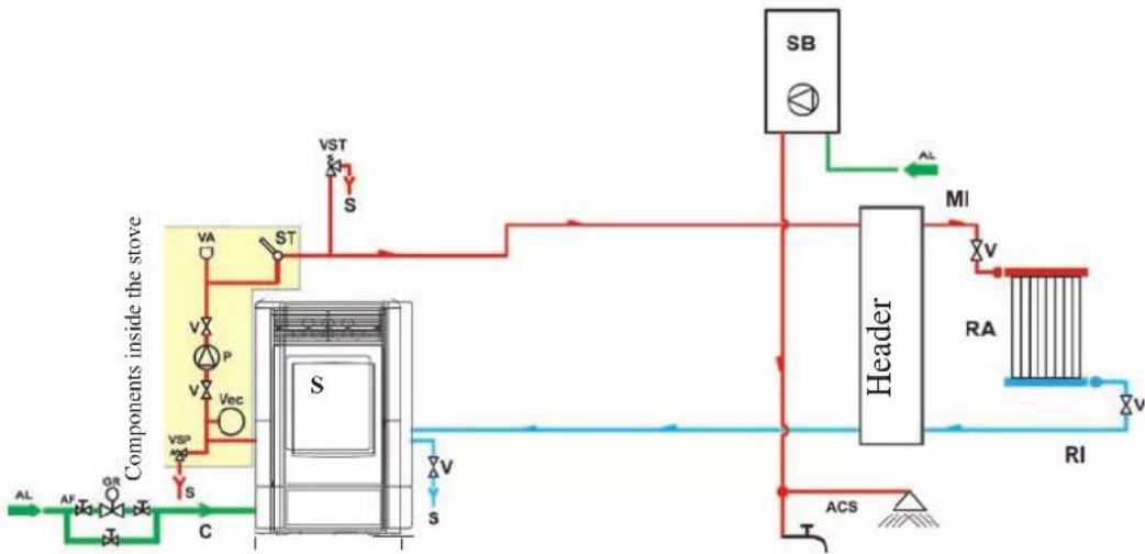
Heating system with stove combined with boiler.
This diagram is indicative; correct execution is the responsibility of the plumber.
flowchart
graph TD
    A["Components inside the stove"] --> B["Valve"]
    B --> C["Stator"]
    C --> D["Header"]
    D --> E["RA"]
    E --> F["RI"]
    F --> G["ACS"]
    G --> H["S"]
    H --> I["VST"]
    I --> J["S"]
    J --> K["Valve"]
    K --> L["Stator"]
    L --> M["Valve"]
    M --> N["Valve"]
    N --> O["Valve"]
    O --> P["Valve"]
    P --> Q["Valve"]
    Q --> R["Valve"]
    R --> S["Valve"]
    S --> T["Valve"]
    T --> U["Valve"]
    U --> V["Valve"]
    V --> W["Valve"]
    W --> X["Valve"]
    X --> Y["Valve"]
    Y --> Z["Valve"]
    Z --> AA["Valve"]
    AA --> AB["Valve"]
    AB --> AC["Valve"]
    AC --> AD["Valve"]
    AD --> AE["Valve"]
    AE --> AF["Valve"]
    AF --> AG["Valve"]
    AG --> AH["Valve"]
    AH --> AI["Valve"]
    AI --> AJ["Valve"]
    AJ --> AK["Valve"]
    AK --> AL["Valve"]
    AL --> AM["Valve"]
KEY
ACS: Domestic Hot Water
CW: Cold water
WS: Water supply
L: Load/refill
PR: Pressure reducer
SO: System output
P: Pump (circulator)
RA: Radiators
SR: System return
D: Discharge
SB: Boiler
WT: Water temp. probe
S: Stove
BV: Ball valve
AV: Automatic air discharge valve
CET: Closed expansion tank
SV: Safety valve
TDV: Thermal discharge valve
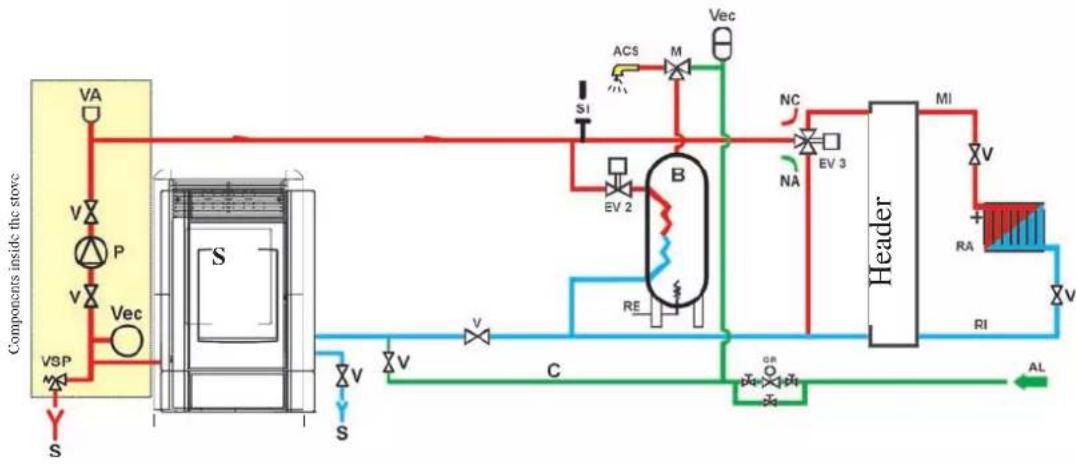
Heating system with stove as the only source of heating and the production of domestic hot water using a boiler
This diagram is indicative; correct execution is the responsibility of the plumber.
flowchart
graph TD
    A["Components inside the stove"] --> B["VSP"]
    B --> C["S"]
    C --> D["V"]
    D --> E["P"]
    E --> F["V"]
    F --> G["Vec"]
    G --> H["VA"]
    H --> I["ACS"]
    I --> J["M"]
    J --> K["Vec"]
    K --> L["Header"]
    L --> M["MI"]
    M --> N["V"]
    N --> O["RA"]
    O --> P["RI"]
    P --> Q["V"]
    Q --> R["AL"]
    R --> S["C"]
    S --> T["RE"]
    T --> U["EV 2"]
    U --> V["B"]
    V --> W["NC"]
    W --> X["EV 3"]
    X --> Y["SI"]
    Y --> Z["Si"]
    Z --> AA["SI"]
    AA --> AB["SI"]
    AB --> AC["SI"]
    AC --> AD["SI"]
    AD --> AE["SI"]
    AE --> AF["SI"]
    AF --> AG["SI"]
KEY
ACS: Domestic Hot Water
WS: Water supply
B: Boiler
L: Load/refill
EC: electronic control unit
EV2: 2-way electric valve
EV3: 3-way electric valve
NO: Normally open
NC: Normally closed
PR: Pressure reducer
SO: System output
P: Pump (circulator)
RA: Radiators
SR: System return
D: Discharge
S: Stove
BV: Ball valve
CET: Closed expansion tank
SV: Safety valve
ACCESSORIES:
In the diagrams on the previous pages, it is assumed that the accessories available on the EDILKAMIN S.p.A. price list are used.
Spare parts are also available separately (exchangers, valves, etc.); consult to your local dealer.
INSTRUCTIONS FOR USE
First Ignition/Testing by the Edilkamin authorised Technical Assistance Centre (TAC)
Start-up must be carried out as prescribed by standard UNI 10683/2012, point 3.21.
The said standard indicates the checks to be carried out during installation, aimed at ensuring the correct operation of the system.
Edilkamin technical assistance (TAC) will also calibrate the stove on the basis of the type of pellets and the installation conditions.
Start-up by the TAC is necessary for the validity of the guarantee.
The first times the stove is lit, there may be a slight smell of paint; this will soon disappear.
Before lighting the stove, check:
==> Correct installation.
==> The electricity supply.
==> The closure of the door, which must be air-tight
==> The cleaning of the crucible.
==> That indication of stand-by mode on the display (date, power or temperature flashing on and off).
LOADING THE PELLETS INTO THE HOPPER
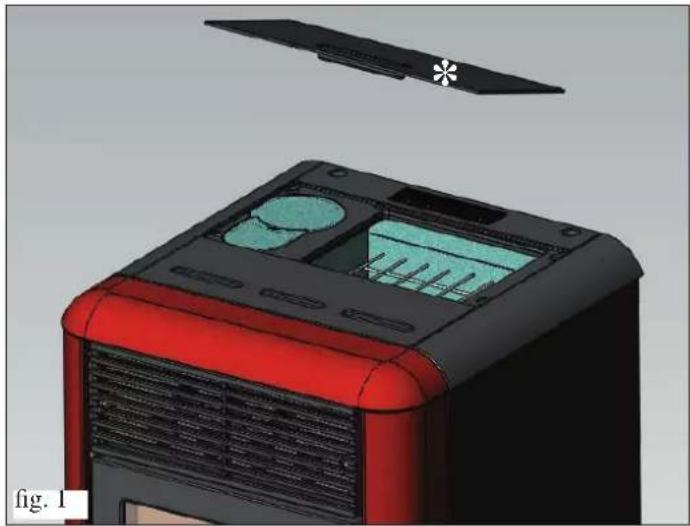
Remove the metallic cover in order to fill the hopper * (fig. 1).
ATTENTION:
If loading the stove during operation, and therefore while hot, use the special glove provided.
During the first ignition carry out the air/water bleeding operation using the manual valve (V) under the steel covers (fig. 2-3).
N.B.: you can see the valve positioned on the right side if the metal right side will be disassembled.
natural_image
3D model of a red and black electronic device casing with ventilation grilles and a star-shaped component above it (no text or symbols)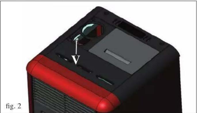
natural_image
3D model of a computer tower with red and black casing, showing internal components and a labeled component (V), no text or symbols present.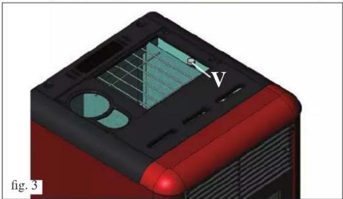
natural_image
3D model of a red and black device casing with internal components and a labeled point 'V', shown in perspective view (no text or symbols beyond label)NOTES on fuel
IDROPOINT is designed and programmed to burn wood pellets with a diameter of about 6 mm.
Pellets are fuel in the form of small cylindrical elements produced by highly compressed sawdust without the addition of glues or other foreign substances.
It is sold in 15 kg bags.
ONLY pellets must be burnt in the stove, otherwise it will NOT function correctly.
If any other material is used (including wood), which can be detected by laboratory analysis, the guarantee shall not be valid.
EDILKAMIN has designed, tested and programmed its own products in order to guarantee best performance with pellets of the following features:
diameter: 6 millimetres
maximum length: 40 mm maximum humidity: 8 %
heat yield: at least 4300 kcal/kg
The use of pellets with other features requires specific calibration of the stove, similar to that carried out by the TAC (Technical Assistance Centre) when the stove is lit for the first time. The use of unsuitable pellets can cause: decreased yield; functioning anomalies; close-down due to clogging; soiled glass; non-combustion; ...
A simple analysis of the pellets can be carried out by visual examination:
Good: smooth, regular length, little dust.
Poor: with longitudinal and transversal cracks, dusty, variable length, presence of foreign bodies.
INSTRUCTIONS FOR USE
SYNOPTIC PANEL


key to set the desired environmental temperature (AIR) or to enter the menu

key to set the water temperature ( H_2O )

on/off or confirm/quit menu key

indicates that the chrono-thermostat has been programmed for automatic ignition at set times

indicates an alarm condition

indicates the functioning of the pellet-loading motor

indicates functioning pump

indicates functioning spark plug
DESCRIPTION OF MENUS
- To access the menus, press and hold the key 15 for 2 seconds (the LED switches off).
Press the key ☐ the key, to fill through the following menus:
- M1: Set clock
- M2: Set time programme
- M3: Language
- M4: Stand-by
- M5: First load
- M6: Status
- M7: Technical calibrations (TAC)
- M8: Type of pellets (TAC)
- M9: Quit
• To confirm the desired menu, press the key

• To return to the previous menu, press the key

• To quit the menu, press the key

SWITCHING ON/OFF
To switch the stove on/off, press the key 12c 3 seconds.
LED on
stove operating
LED flashing
stove being switched off or in alarm state
LED off
stove off
OPERATING
The stove has two operating modes:
- MANUAL:
In the MANUAL operating mode, the water temperature at which the stove must operate is set, independently from the temperature of the room in which it is installed.
The stove automatically adjusts the operating power on the basis of the water temperature, to reach or maintain the set water temperature.
To select the MANUAL operating mode, press the key (the LED comes on) and the message 'AIR' appears with an indication of the temperature.
Pressing the key will increase the temperature until the message 'MAN' appears on the display (above 40°).
To set the water temperature, press the key (the LED comes on) and the message 'H _2 O' will appear.
By means of the key, the key, the water temperature can be changed as desired.
- AUTOMATIC
In AUTOMATIC mode, it is possible to set the water temperature and the desired temperature of the room where the stove is installed.
When the desired environmental temperature (AIR) or the water temperature ( H_2O ) is reached, the stove will automatically adjust itself to minimum power.
To set the desired environmental temperature (AIR), press (the LED comes on); the operating temperature at that mo

ment will be displayed; using the key, the key, the temperature can be changed as desired.
INSTRUCTIONS FOR USE
SCREW LOADING (only if the stove is completely without pellets)
To load the screw, enter the MENU by pressing the key 🖱️ for 2 seconds; then press the key 🔒 until the message “M5 first load” appears on the display.
Press the key 🖼️ confirm, and then the key 🖼️ to ▶ vate the function.
This operation must only be carried out when the stove is off and completely cold.
Note: during this phase, the smoke extractor fan will remain on.
STAND-BY FUNCTION
In this mode, the stove will go off when the temperature of the environment is 0.5^ C higher than that requested, after a set time of 10 minutes (which can be changed by the TAC during installation).
The message "GO STBY" will appear on the display, indicating the minutes remaining before switch-off.
This function is available in both 'AUTOMATIC' or 'MANUAL' mode and in the case of an external thermostat.
If the environmental temperature falls to 2^ C below the set threshold, the stove will start up again (setting modifiable by the TAC during installation).
To activate the function, press the key 🖱️ for about 3 seconds; the message “M1 set clock” will appear on the display; press the key 🖱️ until the message “M4 stand by” appears on the display, then confirm by pressing the key 🖱️.
Press the key to select "ON", then confirm by pressing the key.
To quit the menu "M4 stand by", press the key 🤒 about 6 seconds.
SETTING THE DATE AND TIME
Press the key 🖱️ for about 2 second; the message “M1 set clock” will appear on the display; then confirm by pressing the key 🖱️. The following data will appear in sequence: Day of the week, hour, minutes, day, month, year; these can be changed by pressing the key 🖱️ or the key 🖝️ to confirm, press the key . 🖱️
To quit the menu "M1 set clock", press the key 🤒 about 6 seconds.
EXTERNAL THERMOSTAT
This must be connected by the blue wire (optional code 640560) to the serial port positioned on the back of the stove; it must have a clean, normally open contact (e.g. in the case of an environmental thermostat):
- Open contact = Environmental temperature reached - Closed contact = Environmental temperature not reached
To select ‘E-T’ (external thermostat) mode, press the key 📁 (the LED will light up). Pressing the key 📁 will lower the temperature until the message ‘E-T’ (external thermostat) appears on the display (below 6°).
Note: When the stove is off, the external thermostat cannot switch the stove on or off. If you want to switch the stove on or off outside the set time or outside the 'E-T' (external thermostat) setting, you must always do so using the key
CHRONO-THERMOSTAT FOR DAILY/WEEKLY PROGRAMMING
There are 3 types of programming (daily, weekly, weekend), each of which is independent of the others and thus many combinations are possible according to the user's requirements (time programming is in 10 minute steps).
Press the key for 2 seconds; the message "M1 set clock" will appear on the display (and the LED will go out).
Press the key 🖱️ until the message “M2 set chrono” appears on the display; confirm by pressing the key 🖱️
To visualise the 3 programming modes (daily, weekly, weekend) press the key 🤒 or the key 🤒 and confirm by pressing the key
INSTRUCTIONS FOR USE
Scroll down the following menu (default setting is OFF):
- M2-1: enables the chrono-thermostat
- M2-2: daily programme
- M2-3: weekly programme
- M2-4: weekend programme
- M2-5: Quit
Choose the desired menu and confirm by pressing the key

To set the stove to switch on and off and for time changes press the key or the key then confirm by pressing the key.

To quit the programme press the key 16 about 6 seconds.
Daily programming:
possibility of switching the stove on and off twice throughout the day, repeated every day:
Example: start1 10:00 stop1 12:00
start2 18:00 stop2 22:00
Weekly programming:
possibility of switching the stove on and off 4 times during the day, and to choose the days of the week. For example:
| start1 06:00 stop1 08:00 | start2 07:00 stop2 10:00 | start3 14:00 stop3 17:00 | start4 19:00 stop3 22:00 |
| Monday onTuesday onWednesday offThursday onFriday onSaturday offSunday off | Monday offTuesday offWednesday onThursday offFriday offSaturday offSunday off | Monday onTuesday onWednesday offThursday offFriday offSaturday onSunday on | Monday onTuesday onWednesday onThursday onFriday onSaturday onSunday on |
Weekend programming:
possibility of switching the stove on and off twice during the weekend:
Example: start1 week-end 07:00 stop1 week-end 11:30
Example: start2 week-end 14:20 stop2 week-end 23:50
ELECTRONIC EQUIPMENT
REMOTE CONTROL
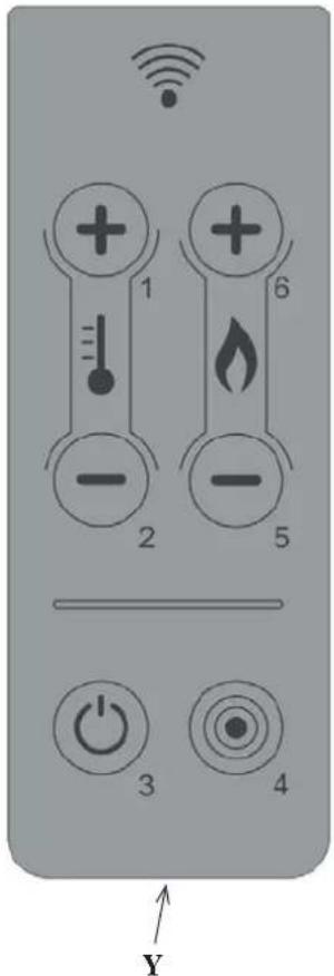
SYMBOLS KEY
3: on/off key, hold down for 2 seconds (short beep confirms when switched on, long beep confirms when switched off)
1: key to increase the desired room temperature (SET ROOM)
2: key to reduce the desired room temperature
6: key to increase the water temperature (SET WATER)
5: key to reduce the water temperature
4: key to open the menu
- the remote control transmits by means of an infrared signal within a range of 4-5 metres.
The LED transmission signal must be in line with the receiving LED of the stove for the signal to be transmitted correctly. This must also be in a free-field environment, therefore, free of obstacles.
- The remote control works with 3V battery. Battery duration depends upon usage, however, the average duration is that of an entire season.
To replace the battery, remove the door, Y, where the battery is housed.
The discharged battery should be properly disposed of in accordance with current regulations in force.
- the remote control must be cleaned with a damp cloth and no detergents or liquids must be sprayed onto it. In any case, use neutral detergents which are free from aggressive substances.
- handle the remote control with care. It could easily break if dropped, due to its size.
NOTES:
- Operating temperature: 0-40 °C
- Storage temperature: -10/+50°C
- Operating humidity is: 20-90% R.H with no condensation
- Degree of protection is: IP 40
- Weight with battery inserted: 15 gr
MAINTENANCE
Before carrying out any maintenance, disconnect the appliance from the mains electricity.
Regular maintenance is the basis of good functioning of the stove.
IF YOU DO NOT PROVIDE FOR THE NECESSARY MAINTENANCE, the stove will not function correctly.
In the case of problems due to lack of maintenance, the guarantee will not be valid.
DAILY MAINTENANCE
Operations to be carried out with the stove off, cold, and disconnected from the electricity supply
• To be carried out with the aid of a vacuum cleaner (see optionals on page 221).
• The whole procedure takes only a few minutes.
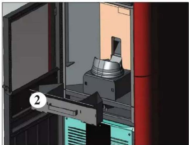
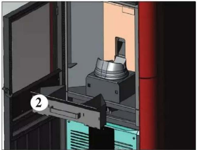
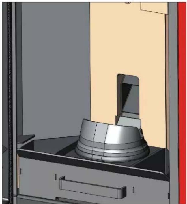
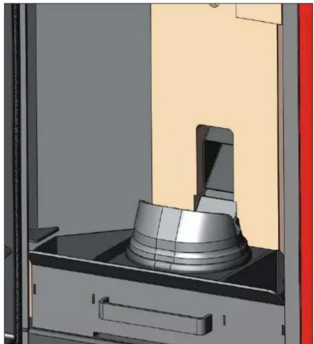
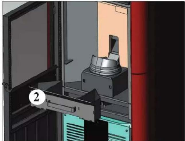
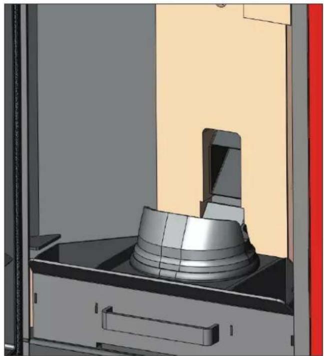
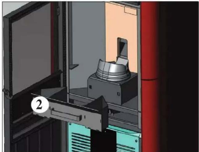
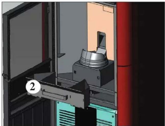
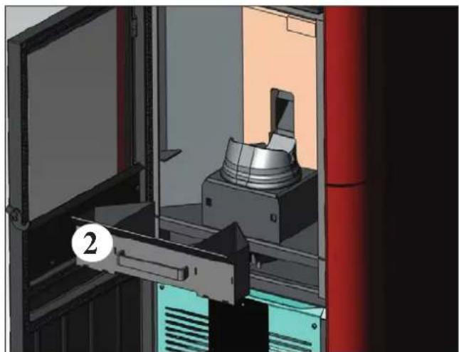
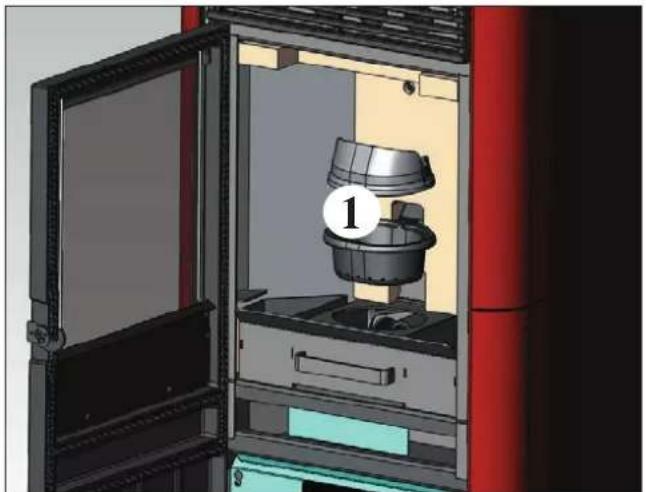
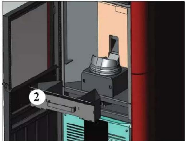
- Open the door, remove the crucible (1 - fig. A) and tip out the residues into the ash tray (2 - fig. B).
• DO NOT TIP THE RESIDUES INTO THE PELLET HOPPER.
- Extract and empty the ash tray (2 - fig. B) into a non-flammable container (it could contain ash which is still hot and/or hot embers).
• Vacuum the inside of the combustion chamber, the combustion surface, and the area around the crucible where ash falls.
- Remove the crucible (1 - fig. A) and remove encrustations with the brush provided; remove any debris clogging the combustion air holes.
• Vacuum the crucible chamber, clean the edges where the crucible comes into contact with its seat.
- If necessary, clean the glass (when cold)
Never vacuum hot ash; it will damage the vacuum cleaner and is a domestic fire risk.
natural_image
3D rendering of a mechanical device with a labeled component (1) inside, showing internal components and no visible text or symbols.fig. A
natural_image
3D rendering of a mechanical device inside a storage cabinet, showing internal components and no visible text or symbolsfig. B
WEEKLY MAINTENANCE
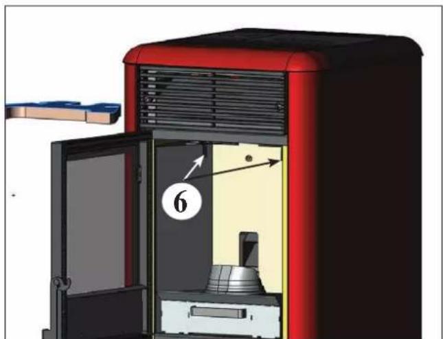
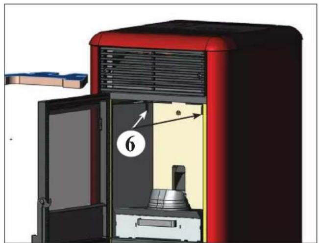
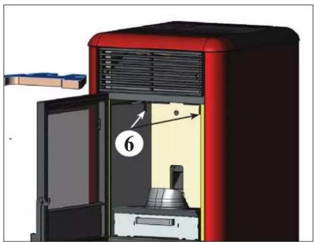
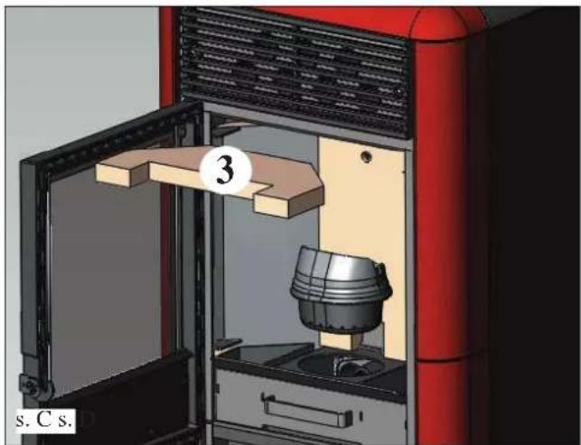
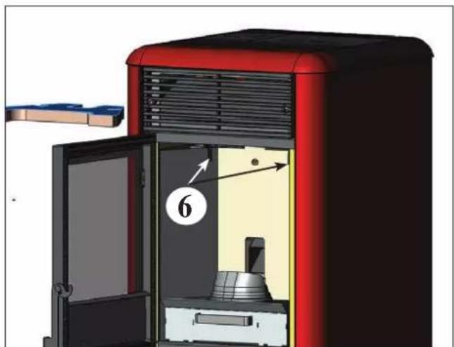
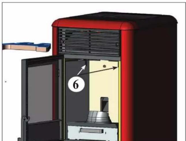
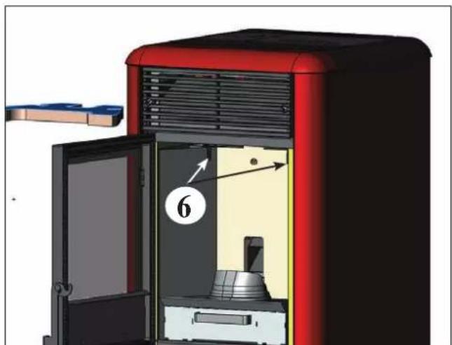
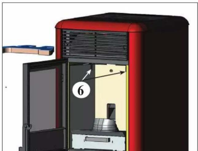
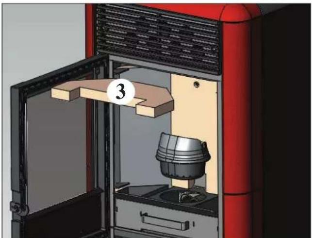
- Extract the ceiling (3 - fig. C), move the brushes (6 - fig. D) and empty the residues into the ash tray (2 - fig. B).
• Empty the pellet hopper and vacuum the bottom.
natural_image
3D rendering of a red industrial machine with a metallic component inside, showing internal components and a numbered label (3) on the door (no text or symbols on the device itself)fig. C

natural_image
3D diagram of a red industrial machine with labeled components and directional arrows (no text or symbols beyond labels)fig. D
MAINTENANCE
SEASONAL MAINTENANCE (by the TAC - technical assistance centre)
- General cleaning, inside and out
- Accurate cleaning of the exchange pipes inside the hot air output grill located in the upper part of the front of the stove
• thorough cleaning and removing encrustation of the crucible and the relative chamber - Cleaning of the smoke extractor fan, mechanical check on play and fixings
- Cleaning of the flue (replacement of the gasket on the flue pipe)
- Cleaning of the smoke duct
- Cleaning of the smoke extractor fan, cleaning of the pressure switch, check on the thermocouple.
- Cleaning, inspection and removal of encrustations on the ignition resistance chamber, replacement of the same if necessary
- Cleaning/check of the synoptic panel
- Visual inspection of the electric wires, of the connections and of the power-supply wire
- Cleaning of the pellet hopper and check on play of the screw-gear motor group
- Replacement of the door gasket
- Test of functioning, screw loading, ignition, operation for 10 minutes and switching off.
If the stove is used very frequently, it is advisable to clean the flue every 3 months.
ATTENTION!!
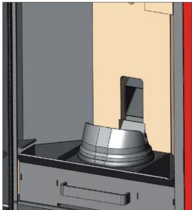
After normal cleaning, INCORRECT attachment of the upper part of the crucible (A) (fig. 1) with the lower part of the crucible (B) (fig. 1) can compromise stove functioning.
Therefore, before igniting the stove, make sure that the two parts of the crucible are correctly attached as indicated in (fig. 2) without any ash or unburnt fuel on the contact edges.
We remind you that using the stove without cleaning the melting pot, may cause a sudden ignition gas inside the combustion chamber with the consequent breaking of the glass
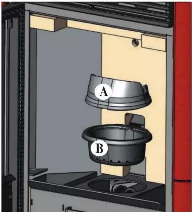
fig. 1 fig. 2
natural_image
3D CAD rendering of a mechanical assembly with a cylindrical component mounted on a base, shown in an open view (no text or symbols visible)ADVICE IN CASE OF PROBLEMS
In the case of problems, the stove will switch off automatically, and an indication of the cause will appear on the display (see the various messages below).
Never pull out the plug when the stove is switching off automatically because of a failure.
In the case of automatic switch-off, the stove must be allowed to complete the entire procedure (15 minutes with an
acoustic signal), after which it can be restarted by pressing the key
However, do not restart the stove until you have found out the cause of the error and until you have CLEANED/EMP-TIED the crucible.
SIGNALS OF POSSIBLE CAUSES OF AN ERROR, TIPS AND SOLUTIONS:
AL1 black out (this is not a stove error) (this takes place if there is no electricity for more than 5 seconds)
The stove has a 'black out' function. It the electricity supply is off for less than 5 seconds, the stove will switch on again, returning to the function in progress before it switched off.
If the electricity supply is off for more than 5 seconds, the stove will go into 'black out' alarm, with consequent cooling phase.
The possible causes are listed below:
| Stove status before black-out Interruption of less than 10 seconds | Interruption of more than 10 seconds | |
| OFF OFF OFF | ||
| PRE-LOAD BLACK OUT BLACK OUT | ||
| IGNITION BLACK OUT BLACK OUT | ||
| START-UP START-UP STAND-BY THEN RE-IGNITION | ||
| OPERATING OPERATING STAND-BY THEN RE-IGNITION | ||
| FINAL CLEANING FINAL CLEANING FINAL CLEANING | ||
| STAND-BY | STAND-BY | STAND-BY |
| ALARM | ALARM | ALARM |
| ALARM RECORD | ALARM RECORD | ALARM RECORD |
AL2 broken smoke temp. probe (when the stove can no longer read the smoke temperature)
- Broken thermocouple
- Detached thermocouple
- Smoke temperature out of range
AL3 hot smoke (when the temperature of the smoke exceeds the safety threshold)
- Blocked chimney
- Incorrect installation
- Stove clogged
- Too many pellets loaded, check pellet feed regulation (TAC)
NOTE: the "hot smoke" message appears when the first alarm threshold of 250^ is exceeded, triggering automatic stove regulation; only when the temperature of 270^ is reached does the stove go into alarm mode and switches itself off.
AL4 fan fault (when the motor of the smoke extractor fan breaks down)
- Smoke extraction motor blocked
• Revolution counter breakdown - Smoke motor breakdown
- Smoke motor thermostat triggered
AL5 ignition failure (when the smoke temperature does not reach the minimum threshold during the ignition phase)
• Probable spark plug failure
- Dirty crucible or too many pellets
• The pellets are finished
- Check the pellet safety thermostat (automatic reset)
- Blocked chimney
AL6 no pellets (when the pellets are finished)
• There are no more pellets in the hopper
• A gear motor failure
• The screw/pellet duct is blocked
- Too few pellets loaded, check pellet feed regulation
ADVICE IN CASE OF PROBLEMS
AL7 thermal safety (when the safety thermostat, situated in contact with the hopper, is triggered by the overheating of the pellet hopper)
- Pellet overloading
AL8 no depression (when there is insufficient draught in the cold air aspiration pipe)
- Blocked cold air pipe
• Pressure switch failure - Blocked silicon pipe
AL9 water temp. probe (when the stove no longer reads the probe)
- Broken water temp. probe
- Disconnected water temp probe
ALA hot water (when the temperature of the water in the boiler is higher than 90°)
- Check the water system
- Check the presence of air in the circuit
- Check the valves/taps of the circuit
- Check the cleaning of the stove
- Check the flue/chimney
- Contact the TAC
FAQ
Very brief answers are given here; for further details, consult the other pages of this document.
1) What must I have to install the stove?
A flue/chimney with a diameter of at least 80 mm.
An air intake vent in the room of at least 80 cm ^4 .
A 34 " G connection for output and return to the header
Discharge into the sewer by a 34'' G overpressure valve
^3/_4 " G load connection
Electrical connection to the system, complying with standards, with 230 V +/- 10%, 50 Hz magneto thermal switch
Check that the primary water circuit is separated from the secondary water circuit.
2) Can I make the stove operate without water?
NO. Functioning without water will damage the stove.
3) Does the stove emit hot air?
NO. Most of the heat produced is transferred to the water.
The stove issues a minimum quantity into the installation room in the form of irradiation from the glass of the combustion chamber.
4) Can I connect the stove output and return directly to a radiator?
NO, as for any other stove/boiler, it must be connected to a header, from which the water is distributed to the radiators.
5) Does the stove also supply domestic hot water?
Domestic hot water can be produced, assessing the power of the stove in terms of the plumbing system.
6) Can I discharge the stove smoke directly through a wall?
NO, correct discharge (UNI 10683) must be at the height of the roof ridge and, in any case, for efficient functioning, a vertical stretch of at least 1.5 metres is necessary; this is in order to avoid the formation of even a small quantity of smoke in the installation room in the case of an electricity black-out.
7) Is an air intake vent necessary in the room where the stove is installed?
Yes, to replace the air used by the stove for combustion; the smoke extractor fan takes air from the room to the crucible.
8) What must I set on the stove display?
The desired water temperature or the desired temperature of the room; the stove will consequently adjust the power to reach and/or maintain the desired temperature.
For small systems, an operating mode can be set which involves switching the stove on and off according to the water temperature reached.
9) How often must I clean the crucible?
Every time it is switched on, when the stove is off and cold.
10) Must I vacuum the pellet hopper?
Yes, at least once a month and when the stove is left off for a period of time.
11) Can I burn other fuels apart from pellets?
NO. The stove is designed to burn wood pellets with a diameter of 6 mm; any other material can damage the stove.
CHECK LIST
To be used as an addition to the complete reading of the technical sheet
Assembly and installation
• Start-up carried out by an authorised TAC which issues the guarantee and the maintenance logbook
- Ventilation of the room
- The flue/chimney must only receive the discharge from the stove
- The flue must have: no more than 2 bends no more than 2 metres of horizontal sections
• a chimney pot above the reflux area
- discharge pipes in suitable material (stainless steel is recommended)
- if the pipes pass through or near any flammable materials (e.g. wood), all fire-prevention precautions must be taken.
Use
- The pellets must be of good quality and not damp
- The crucible and the ash pan must be clean and correctly positioned
• The door must be securely closed
• The crucible must be well inserted into its seat
REMEMBER to ALWAYS VACUUM THE CRUCIBLE BEFORE IGNITION If the stove does not light, do NOT repeat ignition before having emptied the crucible.
BIZTONSÁGI INFORMÁCIÓK
SOHA NE HASZNÁLJA AZ IDROPOINT KÁLYHÁT, HA A RENDSZERBEN NINCS VÍZ.
A „SZÁRAZON” TÖRTÉNŐ BEGYÚJTÁS KÁRT TEHET A KÁLYHÁBAN.
AZ IDROPOINT KÁLYHÁT KB, 1,5 BAR NYOMÁSON KELL ÜZEMELTETNI
natural_image
Cross-sectional diagram of a device casing with internal components and an arrow indicating direction (no text or symbols)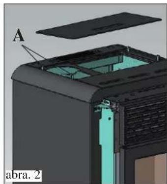
natural_image
3D cutaway view of a device showing internal components and labeled section A (no text or symbols beyond labels)FÜSTKIMENET
natural_image
3D cutaway diagram of a device showing internal components and labeled section 'abra. 4' (no text or symbols beyond label)A FÜSTKIMENET CSATLAKOZTATÁSA A KÁLYHA HÁTOLDALÁN
natural_image
3D cutaway view of a mechanical device showing internal components and housing (no text or symbols visible)A FÜSTKIMENET CSATLAKOZTATÁSA A KÁLYHA BALOLDALÁN
natural_image
3D cutaway view of a device showing internal components labeled I, D, and D (no text or symbols beyond labels)natural_image
3D rendering of a black industrial device with internal structure and ventilation duct (no text or symbols visible)MIUTÁN VÉGZETT A FÜSTELVEZETŐ CSŐ ÉS A FÜSTCSŐ CSATLAKOZTATÁSÁVAL, SZERELJE VISSZA A FÉMOLDALLAPOT, MAJD SZERELJE FEL A KÁLYHA BURKOLATÁT (LD. 230 OLDAL).
ÖSSZESZERELÉS
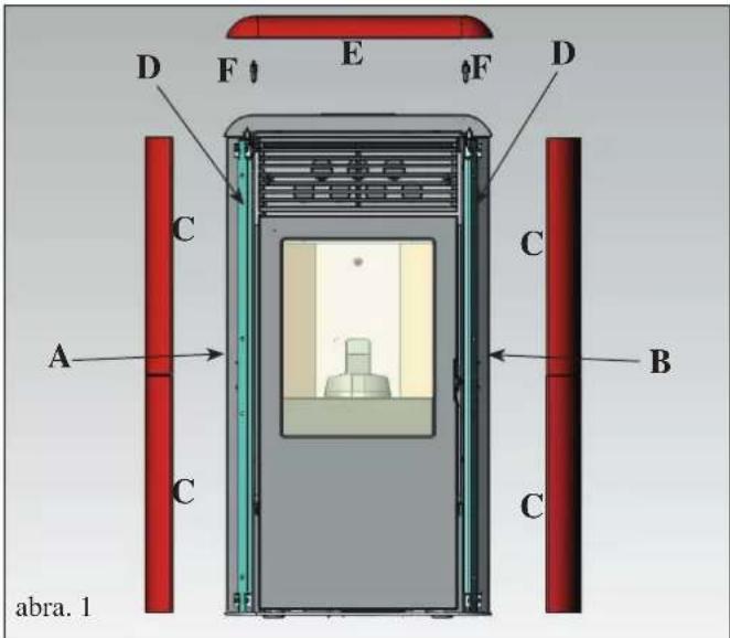
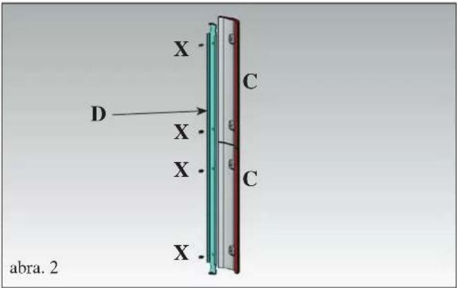
BURKOLAT
natural_image
3D model of a red and black electronic device casing with ventilation grilles and a star-shaped component above it (no text or symbols)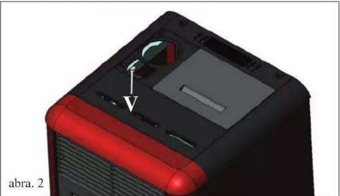
natural_image
3D model of a computer tower with red and black casing, showing internal components and a labeled arrow (no text or symbols beyond label)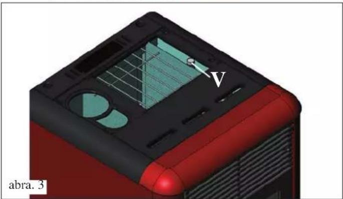
natural_image
3D model of a red and black electronic device casing with internal components and a labeled point V (no text or symbols beyond label)
FONTOS:
natural_image
3D rendering of a mechanical device with a labeled component (1) inside, showing internal components and no visible text or symbols.abra. A abra. B
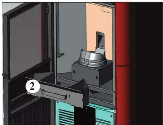
natural_image
3D rendering of a mechanical device inside a transparent enclosure, showing internal components and no visible text or symbols.HETI TISZTÍTÁS
natural_image
3D rendering of a red industrial machine with a metallic component and open door, no visible text or symbolsabra C
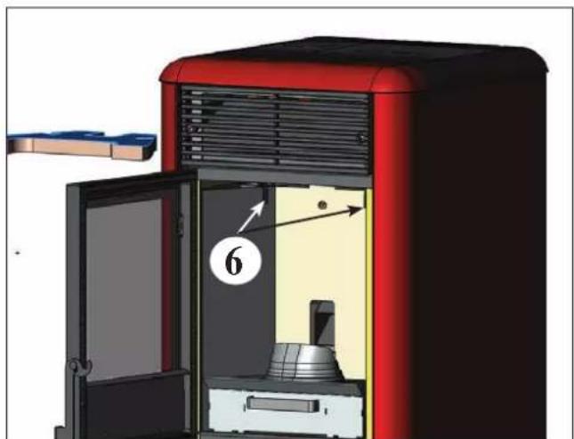
natural_image
3D diagram of a red industrial machine with labeled components and directional arrows (no text or symbols beyond labels)abra D
KARBANTARTÁS
natural_image
3D rendering of a mechanical assembly with a cylindrical component mounted on a base, shown in an open view (no text or symbols visible)HIBAÜZENETEK JELZÉSE ÉS JAVASOLT MEGOLDÁSOK
INFORMACE O BEZPEČNOSTI
KAMNA NESMÍ BÝT NIKDY PROVOZOVÁNA BEZ
VODY V ZAŘÍZENÍ A PŘI TLAKU NIŽŠÍM NEŽ 1 BAR.
PŘÍPADNÉ ZAPÁLENÍ KAMEN „NA SUCHO“ BY KAMNA POŠKODILO ČI ZNIČILO.
natural_image
3D cutaway diagram of a device casing with internal components and an arrow indicating orientation (no text or symbols)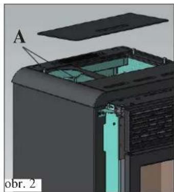
natural_image
3D cutaway view of a device showing internal components and a labeled section (no readable text or symbols)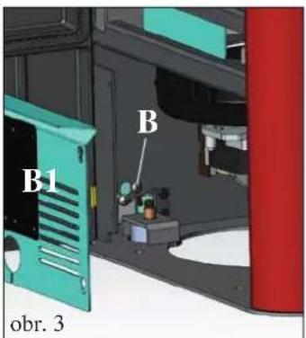
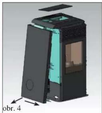
natural_image
3D cutaway view of a device showing internal components and labeled parts (obr. 4), no readable text or symbols beyond the label.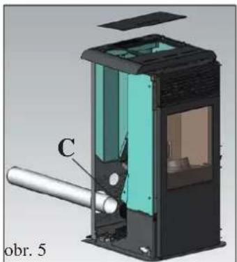
natural_image
Cross-sectional diagram of a device with labeled component C, showing internal structure and housing (no text or symbols beyond label)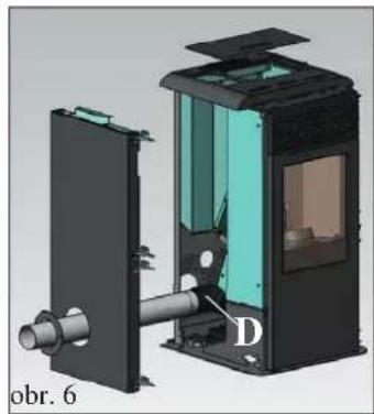
natural_image
3D cutaway view of a mechanical device with labeled component D, showing internal components and housing (no text or symbols beyond label)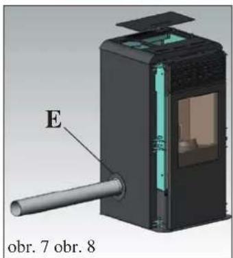
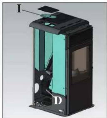
natural_image
3D cutaway view of a device showing internal components labeled I and D (no text or symbols beyond labels)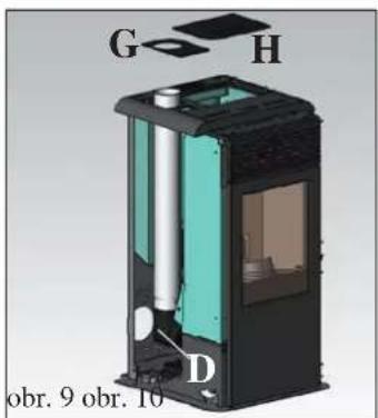
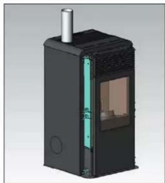
natural_image
3D rendering of a black industrial device with internal structure and ventilation duct (no text or symbols visible)KOUROVOD
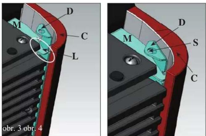
OPLÁŠTĚNÍ
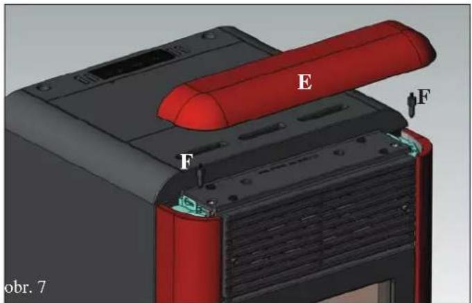
HYDRAULICKÉ PŘIPOJENÍ
( PROVÁDÍ PROŠKOLENÁ INSTALATÉRSKÁ FIRMA )
- KAMNA NESMÍ BÝT NIKDY PROVOZOVÁNA BEZ VODY V ZAŘÍZENÍ A PŘI TLAKU NIŽŠÍM NEŽ 1 BAR.
- PŘÍPADNÉ ZAPÁLENÍ „NA SUCHO“ KAMNA POŠKODÍ NEBO ZNIČÍ.
natural_image
3D model of a red and black electronic device casing with ventilation grilles and a star-shaped component above it (no text or symbols)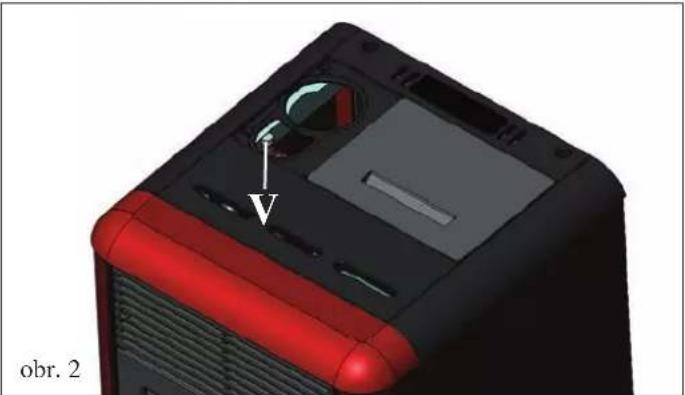
natural_image
3D model of a computer tower with red and black casing, showing internal components and a labeled arrow (no text or symbols beyond label)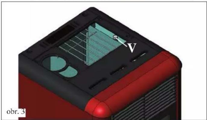
natural_image
3D model of a red and black device casing with internal components and a labeled arrow (no readable text or symbols)POZNÁMKA k palivu:

POZNÁMKY:
natural_image
3D rendering of a mechanical device with a labeled component (1) inside, showing internal components and no visible text or symbols.obr. A
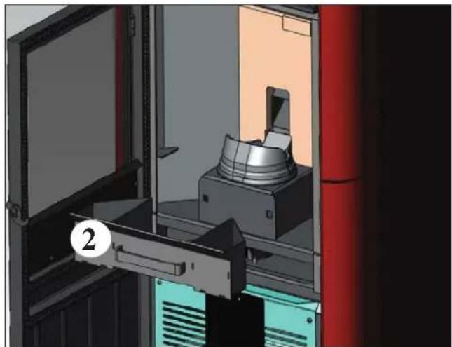
natural_image
3D rendering of a mechanical assembly inside a cabinet, showing internal components and no visible text or symbolsobr. B
TÝDENNÍ ÚDRŽBA
natural_image
3D rendering of a red industrial machine with a labeled component (no text or symbols visible)obr.. C obr. D
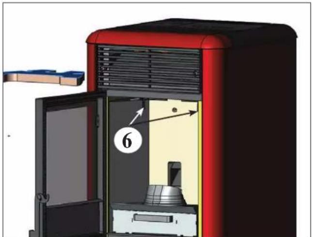
natural_image
3D diagram of a red industrial oven with labeled components and airflow direction arrow (no text or symbols beyond labels)ÚDRŽBA A ČIŠTĚNÍ
natural_image
3D rendering of a mechanical assembly with a cylindrical component mounted on a base, shown in an open view (no text or symbols visible)PORADCE PRI POTÍZÍCH
natural_image
Cross-sectional diagram of a mechanical device showing internal components and a directional arrow (no text or symbols)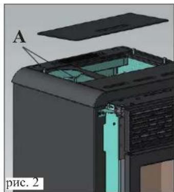
natural_image
3D mechanical assembly diagram showing internal components and part A, labeled 'A' and 'рис. 2' (no readable text or symbols beyond labels)
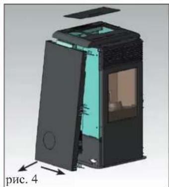
natural_image
3D cutaway view of a device showing internal components and part, labeled 'рис. 4' (no text or symbols on the diagram itself)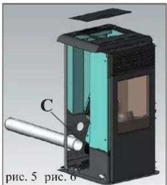
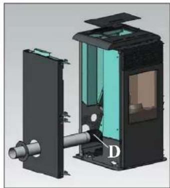
natural_image
3D cutaway view of a mechanical device showing internal components and labeled part D (no text or symbols beyond label)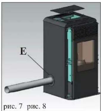
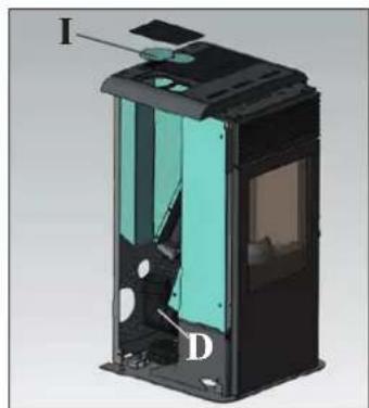
natural_image
3D cutaway view of a device showing internal components labeled I, D, and an unlabeled section (no text or symbols beyond labels)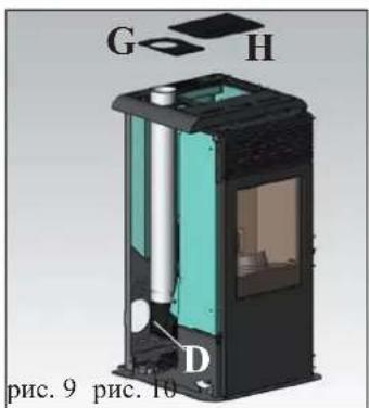
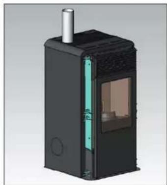
natural_image
3D rendering of a black industrial device with internal structure and ventilation duct (no text or symbols visible)ДЫМОХОД
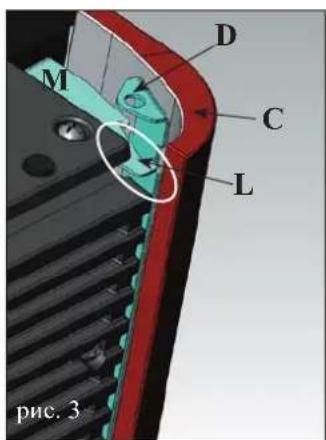
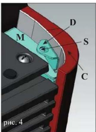
ОБШИВКА
natural_image
3D mechanical assembly diagram showing internal components labeled E, F, and a red cylindrical part (no text or symbols beyond labels)natural_image
3D model of a red industrial air conditioner unit with internal compartments and a black plastic cover (no text or symbols)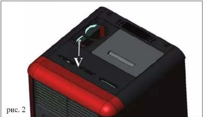
natural_image
3D model of a computer tower with red and black casing, showing internal components and a white arrow pointing to a component (no text or symbols on the object itself)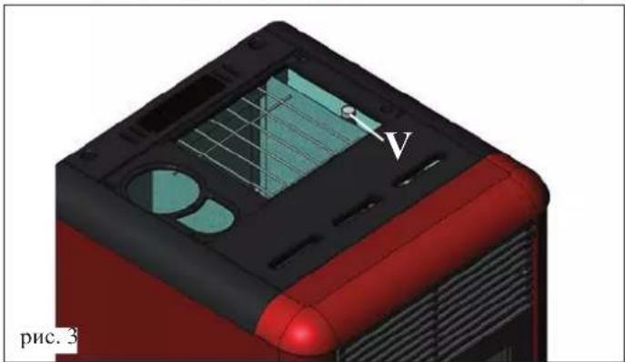
natural_image
3D rendered model of a red and black device casing with internal components and a labeled arrow (no readable text or symbols)
ПРИМЕЧАНИЯ:
natural_image
3D rendering of a mechanical device with a labeled component (1) and open door, showing internal components without any text or symbols.рис. А
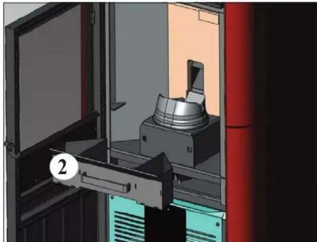
natural_image
3D rendering of a mechanical assembly or machine with a labeled component (2), no visible text or symbols.рис. В
ЕЖЕНЕДЕЛЬНОЕ ОБСЛУЖИВАНИЕ
natural_image
3D rendering of a red industrial machine with a mechanical component inside, showing no visible text or symbols.рис. С
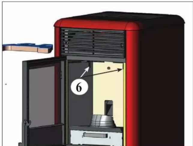
natural_image
3D diagram of a red industrial machine with labeled components and airflow direction arrow (no text or symbols beyond labels)рис. D
ОБСЛУЖИВАНИЕ
natural_image
3D CAD rendering of a mechanical assembly with a cylindrical component mounted inside a housing (no visible text or symbols)рис. 1 рис. 2
VEILIGHEIDSINFORMATIE
IDROPOINT MAG NOOIT FUNCTIONEREN ZONDER WATER IN HET SYSTEEM.
DOOR EEN EVENTUELE "DROGE" ONTSTEKING WORDT DE THERMOKACHEL BESCHADIGD.
IDROPOINT MOET WERKEN MET EEN DRUK VAN ONGEVEER 1,5 BAR.
• VEILIGHEIDSTHERMOSTAAT WATER:
Thermokoppel rookgas
natural_image
Cross-sectional diagram of a device casing with internal components and an arrow indicating direction (no text or symbols)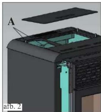
natural_image
3D cutaway view of a device showing internal components and a labeled section (A), no readable text or symbols present.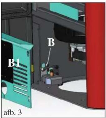
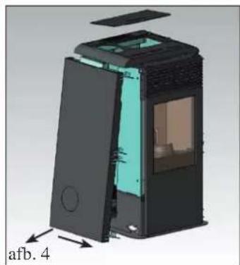
natural_image
3D cutaway diagram of a device showing internal components and labeled part 'afb. 4' (no readable text or symbols beyond label)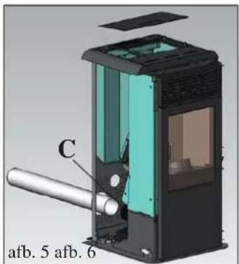
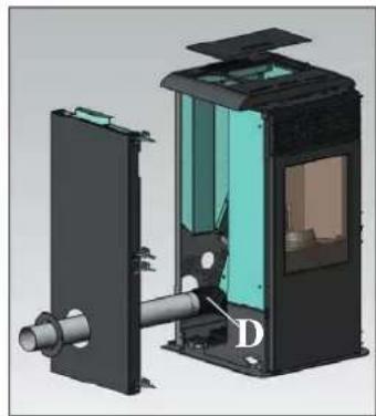
natural_image
3D technical illustration of a mechanical device with internal components and labeled part D (no text or symbols beyond label)
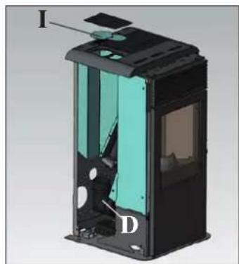
natural_image
3D cutaway view of a device showing internal components labeled I, D, and an unlabeled section (no text or symbols beyond labels)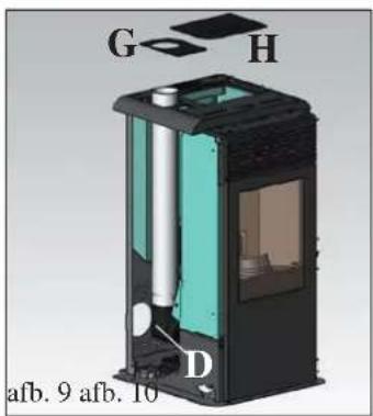
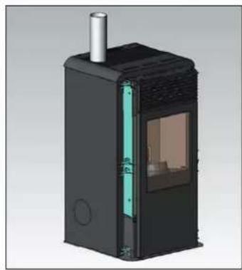
natural_image
3D rendering of a black industrial device with internal structure and ventilation duct (no text or symbols visible)ROOKGASAFVOER
MANTEL
natural_image
3D mechanical assembly diagram showing a red component with labeled parts E and F, no readable text or symbols beyond labelsWATERAANSLUITINGEN
(VOORBEHOUDEN AAN DE DEALER)
- IDROPOINT MAG NOOIT FUNCTIONEREN ZONDER WATER IN HET SYSTEEM.
- DE BEDRIJFSDRUK MOET ONGEVEER 1,5 BAR ZIJN.
- DOOR EEN EVENTUELE "DROGE" ONTSTEKING WORDT DE THERMOKACHEL BESCHADIGD.
natural_image
3D model of a red and black electronic device casing with ventilation grilles and a plastic cover (no text or symbols visible)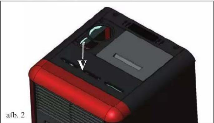
natural_image
3D model of a computer tower with red and black casing, showing internal components and a labeled component 'V' (no text or symbols beyond label)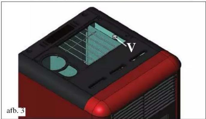
natural_image
3D model of a red and black electronic device casing with visible internal components and a labeled point 'V' (no text or symbols beyond labels)OPMERKING over de brandstof.

natural_image
3D rendering of a mechanical device with a labeled component (1) inside, showing internal components and no visible text or symbols.afb. A
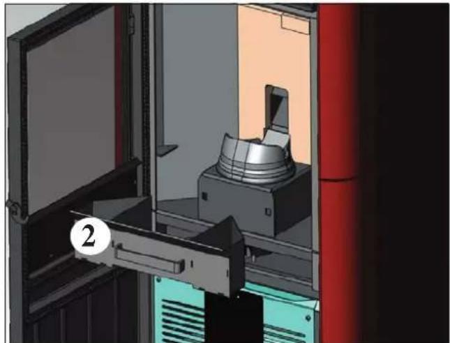
natural_image
3D rendering of a mechanical device inside a storage unit with red pipes and a labeled component (no text or symbols visible)afb. B
WEKELIJKS ONDERHOUD
natural_image
3D rendering of a red industrial machine with a metallic component inside, showing internal components and a numbered label (3) on the door.afb. C
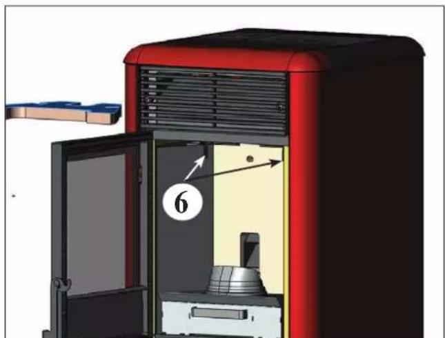
natural_image
3D diagram of a red industrial oven with labeled components and airflow direction arrow (no text or symbols beyond labels)afb. D
ONDERHOUD
natural_image
3D CAD rendering of a mechanical assembly with a cylindrical component and mounting bracket (no visible text or symbols)ADVIES VOOR MOGELIJKE PROBLEMEN

- INFORMAZIONI PER LA SICUREZZA
- USCITA FUMI
- COLLEGAMENTO USCITA FUMI DAL RETRO
- COLLEGAMENTO USCITA FUMI DAL TOP
- ASSEMBLAGGIO
- RIVESTIMENTO
- ALLACCIAMENTI IDRAULICI
- (RISERVATO CENTRO ASSISTENZA TECNICA)
- NOTE:
- MANUTENZIONE
- CONSIGLI PER POSSIBILI INCONVENIENTI
- REVESTIMIENTO
- NOTAS:
- MANTENIMIENTO SEMANAL
- MANTENIMIENTO
- MANTENIMIENTO ESTACIONAL (a cargo del distribuidore)
- CONSEJOS PARA POSIBLES INCONVENIENTES
- INFORMAÇÕES PARA A SEGURANÇA
- SAÍDAS FUMOS
- MONTAGEM
- REVESTIMENTO
- LIGAÇÕES HIDRÁULICAS
- (RESERVADO CENTRO ASSISTÊNCIA TÉCNICA)
- OBSERVAÇÕES:
- MANUTENÇÃO SEMANAL
- MANUTENÇÃO
- CONSELHOS PARA POSSÍVEIS INCONVENIENTES
- ΕΞΟΔΟΣ ΚΑΠΝΑΕΡΙΩΝ
- ΣΥΝΑΡΜΟΛΟΓΗΣΗ
- ΕΠΕΝΔΥΣΗΣ
- ΣΥΝΤΗΡΗΣΗ
- DIMNIK
- ODVOD DIMNIH PLINOV
- PREDEN PRIKLOPITE ODVOD DIMNIH PLINOV SNE- MITE USTREZNO KOVINSKO STRANICO LEVO.
- HIDRA VLIČNI PRIKLJUČKI
- NADZOR NAD TEMPERTATURO POVRATNE VODE
- OPOMBA
- OPOMBA: gorivo
- NAPRAVA NA DALJINKSO UPRAVLJANJE
- LEGENDA SIMBOLOV
- TEDENSKO VZDRŽEVANJE
- VZDRŽEVANJE
- SEZONSKO VZDRŽEVANJE (izvaja CTP)
- Zajema:
- NASVETI ZA ODPRAVO MOREBITNIH NAPAK
- INFORMATIONS POUR LA SÉCURITÉ
- SORTIE DES FUMÉES
- RACCORDEMENT SORTIE FUMÉES PAR L'ARRIÈRE
- RACCORDEMENT SORTIE FUMÉES PAR LE DESSUS
- UNE FOIS L'OPÉRATION DE RACCORDEMENT DU TUYAU DE SORTIE DES FUMÉES AU CONDUIT DE CHEMINÉE TERMINÉE, REMONTER LE CÔTÉ EN MÉTAL GAUCHE PUIS POURSUIVRE AVEC L'ASSEMBLAGE DU REVETEMENT (voir page 120).
- ASSEMBLAGE
- REVÊTEMENT
- RACCORDEMENTS HYDRAULIQUES
- (RÉSERVÉ AU CENTRE D'ASSISTANCE TECHNIQUE)
- Programmation Weekend:
- ENTRETIEN HEBDOMADAIRE
- ENTRETIEN
- CONSEILS EN CAS D'ÉVENTUELS INCONVÉNIENTS
- SICHERHEITSHINWEISE
- Differential-Druckmesser
- RAUCHABZUG
- MONTAGE
- VERKLEIDUNG
- WARTUNG
- TROUBLE SHOOTING
- INFORMACJE DOTYCZĄCE BEZPIECZEŃSTWA
- ODPROWADZENIE SPALIN
- OBUDOWA
- LEGENDA
- M2-2 Programator Dzienny
- KONSERWACJA COTYGODNIOWA
- KONSERWACJA
- POSTĘPOWANIE W PRZYPADKU NIEPRAWIDŁOWOŚCI
- OPLYSNINGER VEDR∅RENDE SIKKERHE- DEN
- R∅GUDGANG
- TILSLUTNING AF R∅GUDGANG FRA BAGSIDEN
- SAMLING
- BEKLÆDNING
- (RESERVERET FOR TEKNISK SERVICECENTER)
- BEHANDLING AF VANDET
- PÄFYLDNING AF PILLER I BEHOLDEREN
- UGENTLIG VEDLIGEHOLDELSE
- VEDLIGEHOLDELSE
- GODE RÅD FOR EVENTUELLE PROBLEMER
- NOTE
- - Starting up/testing
- OPERATING PRINCIPLE
- SAFETY INFORMATION
- ELECTRONIC APPARATUS
- MOTHERBOARD
- SERIAL PORT
- BACKUP BATTERY
- SAFETY DEVICES
- • THERMOCOUPLE:
- • DIFFERENTIAL PRESSURE SWITCH:
- • SAFETY THERMOSTAT:
- • WATER SAFETY THERMOSTAT:
- FEATURES
- N.B.
- SAFETY AND MEASURING DEVICES
- Smoke thermocouple
- Differential pressure switch
- Screw safety thermostat
- Water temp. probe
- Water safety thermostat, with manual reset
- Pressure safety valve
- Pressure meter
- COMPONENTS
- Resistance
- Smoke extractor fan
- Gear motor
- Pump (circulator)
- Closed expansion tank
- Bleed valves:
- CHECK OF COMPATIBILITY WITH OTHER DEVICES
- CHECK THE ELECTRICAL CONNECTION (the socket must be in an easily accessible position)
- FIRE PREVENTION SAFETY DISTANCE
- AIR INTAKE VENT
- SMOKE DISCHARGE
- TYPICAL CASES
- CHIMNEY POT
- INSTALLATION
- SMOKE OUTPUT
- FOR THE CONNECTION OF THE SMOKE OUTPUT TO THE CHIMNEY, WHETHER FROM THE BACK, SIDE OR TOP, IT IS NECESSARY TO REMOVE THE LEFT SIDE.
- REAR SMOKE OUTPUT CONNECTION
- TOP SMOKE OUTPUT CONNECTION
- AFTER COMPLETING THE CONNECTION OF THE SMOKE OUTPUT PIPE TO THE FLUE, REPLACE THE LEFT METAL SIDE AND THEN CONTINUE WITH THE APPLICATION OF THE CASING (see page 208).
- ASSEMBLY
- CASING
- Fig. 1/2/3
- Fig. 3/4
- Fig. 5/6/7
- Fig. 4/8
- PLUMBING
- (FOR TECHNICAL ASSISTANCE CENTRE USE ONLY)
- WATER TREATMENT
- NOTES ON THE RETURN WATER TEMPERATURE
- - FIRST IGNITION
- Heating system with the Stove as the only heat source.
- KEY
- Heating system with stove combined with boiler.
- Heating system with stove as the only source of heating and the production of domestic hot water using a boiler
- ACCESSORIES:
- INSTRUCTIONS FOR USE
- First Ignition/Testing by the Edilkamin authorised Technical Assistance Centre (TAC)
- LOADING THE PELLETS INTO THE HOPPER
- ATTENTION:
- NOTES on fuel
- diameter: 6 millimetres
- heat yield: at least 4300 kcal/kg
- SYNOPTIC PANEL
- DESCRIPTION OF MENUS
- SWITCHING ON/OFF
- OPERATING
- - MANUAL:
- - AUTOMATIC
- SCREW LOADING (only if the stove is completely without pellets)
- STAND-BY FUNCTION
- SETTING THE DATE AND TIME
- EXTERNAL THERMOSTAT
- CHRONO-THERMOSTAT FOR DAILY/WEEKLY PROGRAMMING
- Daily programming:
- Weekly programming:
- Weekend programming:
- ELECTRONIC EQUIPMENT
- REMOTE CONTROL
- SYMBOLS KEY
- NOTES:
- MAINTENANCE
- DAILY MAINTENANCE
- WEEKLY MAINTENANCE
- SEASONAL MAINTENANCE (by the TAC - technical assistance centre)
- ATTENTION!!
- ADVICE IN CASE OF PROBLEMS
- SIGNALS OF POSSIBLE CAUSES OF AN ERROR, TIPS AND SOLUTIONS:
- FAQ
- 1) What must I have to install the stove?
- 2) Can I make the stove operate without water?
- 3) Does the stove emit hot air?
- 4) Can I connect the stove output and return directly to a radiator?
- 5) Does the stove also supply domestic hot water?
- 6) Can I discharge the stove smoke directly through a wall?
- 7) Is an air intake vent necessary in the room where the stove is installed?
- 8) What must I set on the stove display?
- 9) How often must I clean the crucible?
- 10) Must I vacuum the pellet hopper?
- 11) Can I burn other fuels apart from pellets?
- CHECK LIST
- To be used as an addition to the complete reading of the technical sheet
- Assembly and installation
- Use
- BIZTONSÁGI INFORMÁCIÓK
- FÜSTKIMENET
- A FÜSTKIMENET CSATLAKOZTATÁSA A KÁLYHA HÁTOLDALÁN
- A FÜSTKIMENET CSATLAKOZTATÁSA A KÁLYHA BALOLDALÁN
- MIUTÁN VÉGZETT A FÜSTELVEZETŐ CSŐ ÉS A FÜSTCSŐ CSATLAKOZTATÁSÁVAL, SZERELJE VISSZA A FÉMOLDALLAPOT, MAJD SZERELJE FEL A KÁLYHA BURKOLATÁT (LD. 230 OLDAL).
- ÖSSZESZERELÉS
- BURKOLAT
- FONTOS:
- HETI TISZTÍTÁS
- KARBANTARTÁS
- HIBAÜZENETEK JELZÉSE ÉS JAVASOLT MEGOLDÁSOK
- INFORMACE O BEZPEČNOSTI
- KOUROVOD
- OPLÁŠTĚNÍ
- HYDRAULICKÉ PŘIPOJENÍ
- ( PROVÁDÍ PROŠKOLENÁ INSTALATÉRSKÁ FIRMA )
- POZNÁMKA k palivu:
- POZNÁMKY:
- TÝDENNÍ ÚDRŽBA
- ÚDRŽBA A ČIŠTĚNÍ
- PORADCE PRI POTÍZÍCH
- ДЫМОХОД
- ОБШИВКА
- ПРИМЕЧАНИЯ:
- ЕЖЕНЕДЕЛЬНОЕ ОБСЛУЖИВАНИЕ
- ОБСЛУЖИВАНИЕ
- VEILIGHEIDSINFORMATIE
- • VEILIGHEIDSTHERMOSTAAT WATER:
- Thermokoppel rookgas
- ROOKGASAFVOER
- MANTEL
- WATERAANSLUITINGEN
- (VOORBEHOUDEN AAN DE DEALER)
- OPMERKING over de brandstof.
- WEKELIJKS ONDERHOUD
- ONDERHOUD
- ADVIES VOOR MOGELIJKE PROBLEMEN
Brand : EDILKAMIN
Model : IDROPOINT
Category : Boiler