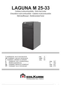
LAGUNA W 25-35 - Boiler EDILKAMIN - Free user manual and instructions
Find the device manual for free LAGUNA W 25-35 EDILKAMIN in PDF.


| Product Type | Wood Boiler |
| Brand | Edilkamin |
| Model | LAGUNA W 25 / LAGUNA W 35 |
| Nominal Water Power | 22.6 kW (W25) / 26.9 kW (W35) |
| Efficiency | 77.7% (W25) / 77.6% (W35) |
| Flue Gas Temperature | 118°C (W25) / 130°C (W35) |
| Fuel Consumption | 6.3 kg/h (W25) / 7.5 kg/h (W35) |
| Water Content | 112 L (W25) / 128 L (W35) |
| Max Operating Pressure | 2 bar |
| Max Water Temperature | 90°C |
| Heatable Volume | 590 m³ (W25) / 700 m³ (W35) |
| Flue Pipe Diameter | 150 mm |
| Weight with Packaging | 430 kg (W25) / 530 kg (W35) |
| Dimensions (W x D x H) | 62 x 90-107 x 152 cm |
| Power Supply | 230 V AC 50 Hz, 120 W |
| Electrical Protection | Fuse T6.3A 250 V |
| Fuel Type | Wood logs (humidity < 20%, length 330-500 mm) |
| Main Functions | Manual ignition, automatic regulation, modulation, standby, safety |
| Safety | Safety heat exchanger, bulb thermostat, temperature probe, electrical safety |
| Maintenance and Cleaning | Manual chamber cleaning every 3-4 days, tubular bundle every month, seasonal maintenance by CAT |
| Spare parts and reparability | Original Edilkamin parts, repairs by authorized CAT |
| General Information | Compliant with EN 303-5, installation by qualified personnel, first startup by CAT |
Frequently Asked Questions - LAGUNA W 25-35 EDILKAMIN
User questions about LAGUNA W 25-35 EDILKAMIN
0 question about this device. Answer the ones you know or ask your own.
Ask a new question about this device
Download the instructions for your Boiler in PDF format for free! Find your manual LAGUNA W 25-35 - EDILKAMIN and take your electronic device back in hand. On this page are published all the documents necessary for the use of your device. LAGUNA W 25-35 by EDILKAMIN.
USER MANUAL LAGUNA W 25-35 EDILKAMIN
natural_image
Exterior view of a large industrial oven or reactor unit (no visible text or symbols on the main body)UK Installation, use and maintenance
natural_image
Technical line drawing of a multi-tiered industrial machine with internal components and mounting holes (no text or symbols)natural_image
Pile of sliced dried root pieces, likely herbal medicine or herbal medicine (no text or symbols visible)natural_image
Illustration of stacked wooden crates with red X marks (no text or symbols)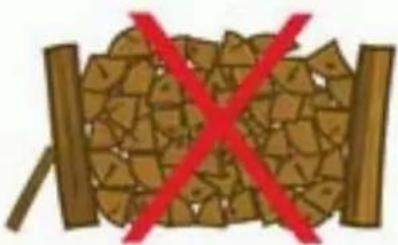
natural_image
Illustration of a broken wooden log with a red X symbol crossed out (no text or symbols present)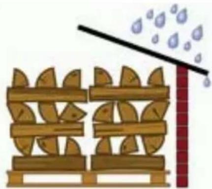
natural_image
Illustration of a wooden fence with leaf-shaped supports and a diagonal line above it, emitting raindrops (no text or symbols)misure espresse in cm
INSTALLAZIONE
AVVERTENZE
INSTALLAZIONE
TETTO INCLINATO
natural_image
Coiled stainless steel valve with red valve and terminal connector (no text or symbols visible)T.Puffer – Temperatura sonda puffer [°C]
natural_image
Technical line drawing of a door opening with internal components (no text or symbols)ISTRUZIONI D'USO
• MANCATA ACCENSIONE
natural_image
Technical line drawing of a mechanical component with mounting holes and a control knob (no text or symbols)ISTRUZIONI D'USO
natural_image
Technical line drawing of a multi-level industrial machine with internal compartments and mounting features (no text or symbols)natural_image
Technical line drawing of a mechanical housing or enclosure with two cylindrical components and internal components (no text or symbols)natural_image
Close-up of a metal bracket component being handled, showing part 1 and part 2 (no text or symbols visible)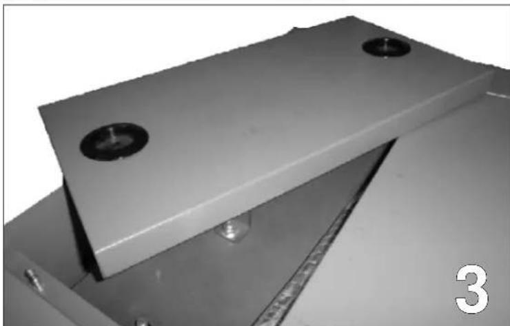
natural_image
Close-up of a metallic mechanical component with two circular holes and a ruler, no visible text or symbolsnatural_image
Close-up of a brush cleaning or polishing process inside a rectangular container with circular holes (no visible text or symbols)natural_image
Close-up of a metallic mechanical component with circular holes and a central rod, no visible text or symbolsThank you for choosing one of our products.
Before using it, we would ask you to carefully read this data sheet, to achieve the best performance and utmost safety when in use.
For further clarifications or requirements, contact the DEALER where you bought the product or visit our website www.edilkamin.com in the section TECHNICAL SUPPORT CENTRES.
The author EDILKAMIN S.p.A. with its registered office in Via Vincenzo Monti 47 - 20123 Milan - Tax Code/VAT No. 00192220192
Declares under its responsibility that: The wood-burning boiler complies with Machinery Directive 89/106/EEC (Building products)
WOOD-burning boiler, under the commercial brand EDILKAMIN, called LAGUNA W
SERIAL NO. Ref. Data plate
YEAR OF MANUFACTURE: Ref. Data Plate
Compliance with the requirements of Directive 89/106/EEC is also determined by compliance with the European Directive: EN 303-5:1999
EDILKAMIN S.p.A. cannot be held in any way liable for the malfunctioning of the appliance in the event of replacement, assembly and/or changes made by staff who do not work for EDILKAMIN without the author's authorisation.
This documentation must be kept for identification together with the receipt whose data should be communicated if you request any information and made available in the event of maintenance intervention.
- the graphically and geometrically represented parts are approximate.
CONTENT
SAFETY INFORMATION......44
GENERAL INFORMATION...... 45
INSTALLATION....50
INSTRUCTIONS FOR USE....62
MAINTENANCE....76
POSSIBLE TROUBLESHOOTING....79
DEMOLITION AND DISPOSAL....80
NOTES 81
SAFETY INFORMATION
GENERAL WARNINGS FOR THE USER
- The instructions manual is an integral part of the product: ensure it always accompanies the appliance so the user, installation technician or plant manager can consult it.
- Carefully read this manual before carrying out any operations on the product.
- Carefully keep this booklet for further consultation.
- Have the authorised EDILKAMIN Technical Support Centre (TSC) carry out a test according to the specifications in this manual and in compliance with all local regulations, including those referencing national and European standards.
- For installation, in Italy, you need to refer to the Declaration of Conformity in compliance with M.D. 37/2008 (previously L. 46/90) and according to the standards UNI 10683 and UNI 10412-2.
- The manufacturer cannot be held liable for damage to property, people or animals due to wrong installation or improper use of the product.
- Before carrying out any cleaning or maintenance operations on the product, disconnect the product from the power mains and/or using the shut-off units by-pass the product on the hydraulic system.
- In the event of a fault/poor functioning of the product, de-active it. Do not attempt any repair or intervention operations.
- Possible repair should only be carried out by the authorised EDILKAMIN Technical Support Centre (TSC), exclusively using original spare parts.
- Use is forbidden of the product by children or incapable people without supervision.
- Connect the product to an electrical socket with voltage 230 V – 50 Hz.
- Connect the product to the heating system. This cannot in any case be used without the plumbing connection and without the water load.
-
Check the electrical system and the sockets have the capacity to support maximum absorption of the product outlined in the manual.
-
Ensure the installation premises of the product is suitable and with minimum ventilation openings according to the specifications in the standards in force.
- Any tampering, replacement and/or changes which are unauthorised on parts of the product can cause danger for the user's safety and relieve the manufacturer of any liability.
- Any tampering, replacement or changes to the electronic part other than that outlined in the manual will cause the warranty to expire.
- Hot ash cannot be thrown in bins or left unguarded.
- It is forbidden to change the safety or regulation devices.
- Do not pull, twist or remove electrical cables.
- It is forbidden to handle easily infl ammable or explosive substances near the boiler when on.
- Do not use the product differently from its intended use.
GENERAL INFORMATION
PACKAGING AND TRANSPORT
The boiler is delivered complete with all its electrical, mechanical and plumbing parts and tested in the factory.
NOTE
- Having unpacked the product, ensure the content is intact and complete (accessories for manual cleaning, warranty booklet, technical data sheet).
- the serial number, necessary for boiler identifi cation, is indicated:
- in the packaging
- on the warranty booklet
- on the plate applied to the rear of the appliance;
The boiler should always be moved in the vertical position using manual or mechanical lifts, which can lift the pallet on which the boiler is packaged or the boiler directly.
The boiler is arranged with a hook to lift as shown in the figure.
natural_image
Technical line drawing of a mechanical device with internal components and mounting features (no text or symbols)GENERAL INFORMATION
MACHINE DESCRIPTION
The boiler was designed to produce hot water using solid biomass in the form of wood as the fuel.
The boiler was designed and built according to standard EN 303-5.
The boiler was designed for connection to heating systems.
We will now give a short description of the boiler functioning principle.
Combustion takes place via a fan (or smoke extractor); the boiler works in negative pressure with an inverse flame to gasification to obtain maximum combustion yield. The power is modulated by a fan, placed on smoke output, based on the flame temperature, and also the working temperature of the boiler set.
The wood is manually loaded by the operator via the door which, on opening, brings the fan to maximum speed to evacuate the smoke from the combustion chamber.
The combustion chamber is immersed in water contained in the cavities. The heat is exchanged by conduction and radiated from the flame and by convection through the path taken by the smoke towards the chimney flue.
The water, once heated, will flow in the system via the circulator (not included).
The boiler is equipped with a:
- Safety exchanger
- Smoke by-pass on opening the loading chamber
• Primary and secondary air shutter
• Catalyser in refractory material
• Covering insulation
• Accessories to clean tube bundle
FUEL USED
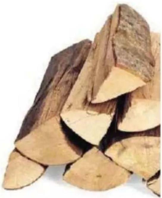
The boiler only burns wooden logs.
The wood used must be good quality and comply with the requirements of Standard EN 14961-5.
• Humidity content not over 20%.
- Variable wood length from 330 mm to 500 mm (according to the model).
- Piece sections 20-100 mm.
• Heat power ≥ 4.0 kWh/kg.
It is important to use dry wood with has been drying for two years.
The following types of wood are recommended: oak, beech, acacia, turkey oak, ash, fi r, pine, larch and birch.
Do not use entire round sections because the entire round wood section would obstruct the air flow inside.
natural_image
Close-up of sliced dried root pieces, possibly herbal medicine or herbal medicine, with no visible text or symbols.GENERAL INFORMATION
WARNINGS AND ADVICE ON FUEL
Using the boiler to dispose of waste causes emission of aggressive smoke that can as a result corrode the equipment, damage the chimney fl ue and pollute the air and the environment.
Damage causes high costs to maintenance and repairs, considerably superior to the costs of regular disposal of waste.
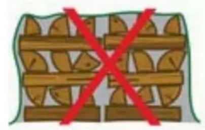
CORRECT WOOD STORAGE
• Storage is of utmost importance to maintain the quality of the wood to burn.
- Wood should be stored already cut and ready for use.
- Storage should be for a minimum of two years.
- Store the stacked wood in a dry place protected from rain.
- Create a dry base for storage and keep separated from the ground to enable airing of at least 20~cm (e.g. stack over long sections).
- Store in places exposed to SOUTHERLY winds.
- When stacking near a building, keep a space of at least 5-10 cm between the stack and the wall.
natural_image
Illustration of stacked wooden crates with a red 'X' symbol crossed out (no text or symbols present)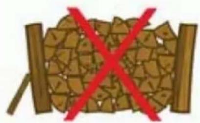
natural_image
Illustration of a wooden log with broken wood and red X symbol (no text or symbols)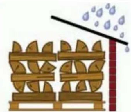
natural_image
Illustration of a wooden fence with leaf patterns and a diagonal line above a red brick wall (no text or symbols)GENERAL INFORMATION
TECHNICAL DATA
| LAGUNA W 25 | LAGUNA W 35 | ||
| Power to firebox | 29.1 | 34.7 | kW |
| Power to water | 22.6 | 26.9 kW | |
| Yield | 77.7 | 77.6 | % |
| CO emission at 10% O_2 | 31 | 32 | mg/m ^3 |
| Smoke temperature | 118 | 130 | °C |
| Fuel consumption | 6.3 | 7.5 | kg/h |
| Draft | 0.12 - 0.05 | 0.12 - 0.05 | mbar |
| Water content | 112 | 128 Litres | |
| Max water operating pressure | 2 | 2 | bar |
| Max H_2O operating temperature | 90 | 90 | °C |
| Water side load loss | 200 a ΔT = 20 K - 750 at ΔT = 10 K | 200 a ΔT = 20 K - 750 at ΔT = 10 K | mbar |
| Heatable volume * | 590 | 700 m | ^3 |
| ∅ smoke pipe (male) | 150 | 150 mm | |
| Weight with packaging | 430 | 530 | kg |
| TECHNICAL DATA FOR CHIMNEY FLUE DIMENSIONING which must however comply with the instructions in the data sheet and the installation standards of each product | |||
| LAGUNA W 25 LAGUNA W | 35 | ||
| Power to fi rebox 29.1 34.07 kW | |||
| Smoke outlet temperature on discharge | 142 156 °C | ||
| Minimum draft 0 - 0.05 0 - 0.05 mbar | |||
| Smoke capacity 12.4 17.4 g/s | |||
* The heatable volume is calculated considering home insulation pursuant to L 10/91 and subsequent amendments and a heating requirement of 33 Kcal/m ^3 per hour.
* It is important to also take into consideration the location of the boiler in the environment to heat.
| ELECTRICAL CHARACTERISTICS | |
| Power supply 230Vac +/- 10% 50 Hz | |
| On/off switch | yes |
| Average absorbed power | 120 W |
| Protection on electronic board | Fuse T6,3A, 250 Vac 5x20 |
The data outlined above are approximate and relate to the certification phase carried out by the notified body.
EDILKAMIN s.p.a. reserves the right to change the products without prior notification at its discretion.
N.B.:
- Changes made by unauthorised staff are forbidden
- Use spare parts recommended by the manufacturer
- Use of non-original spare parts causes the warranty to expire
GENERAL INFORMATION
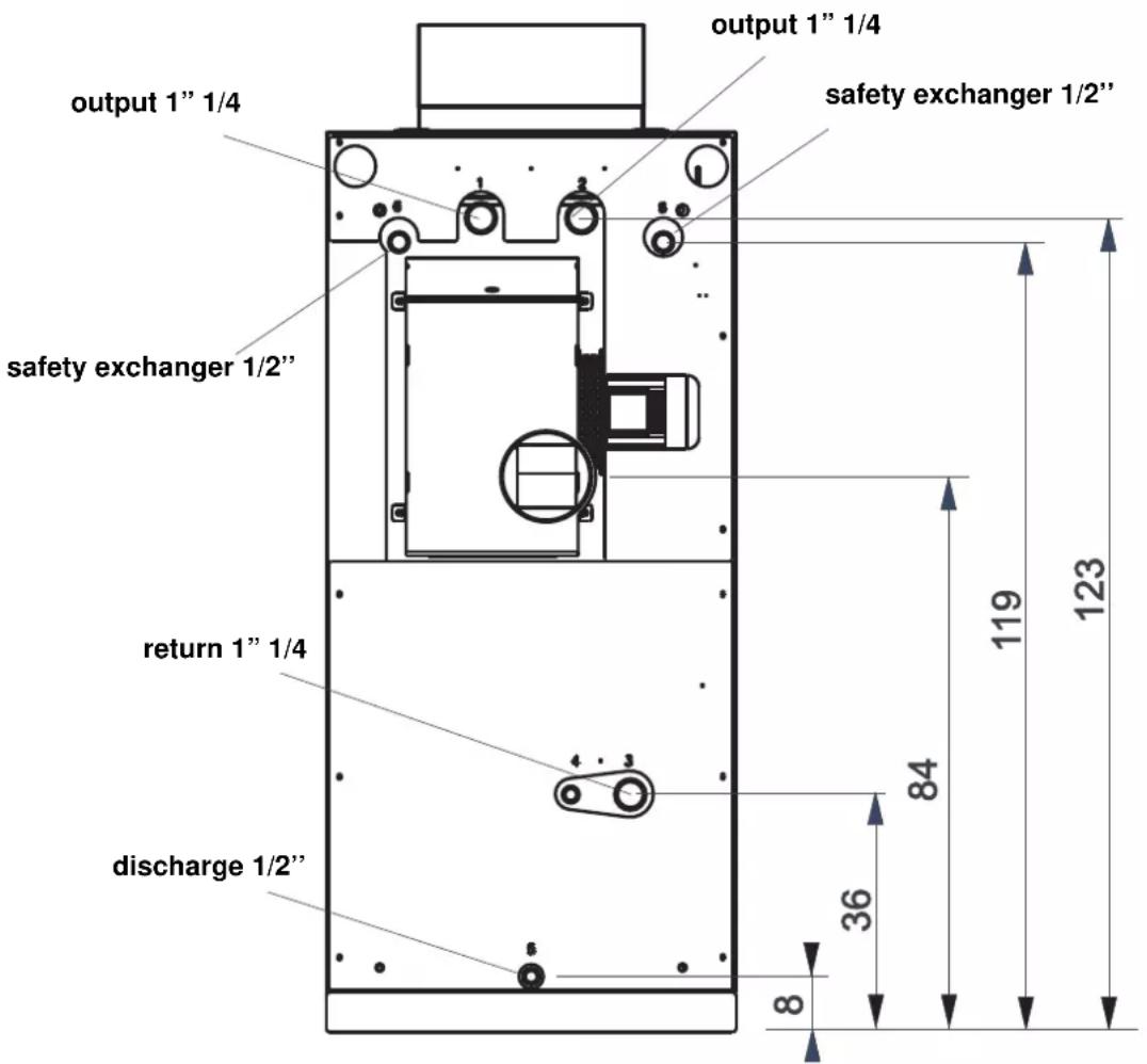
DIMENSIONS
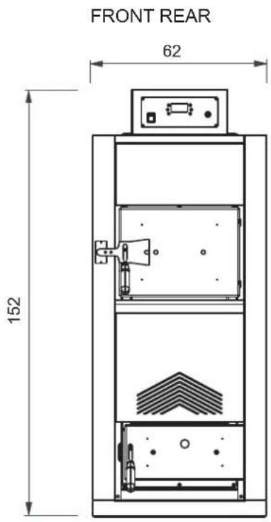
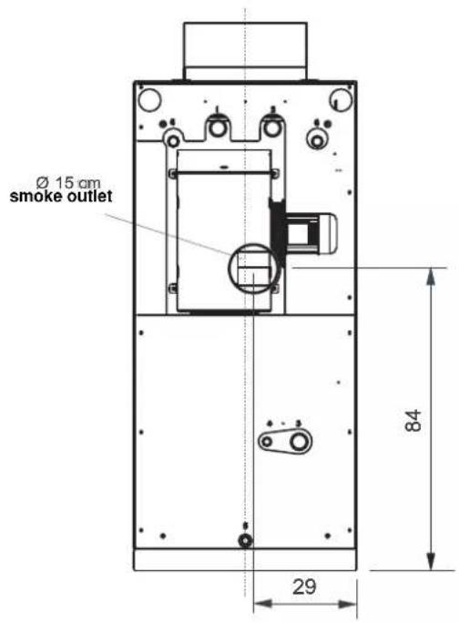
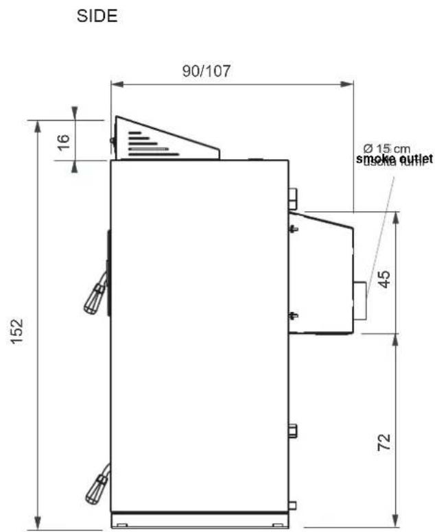
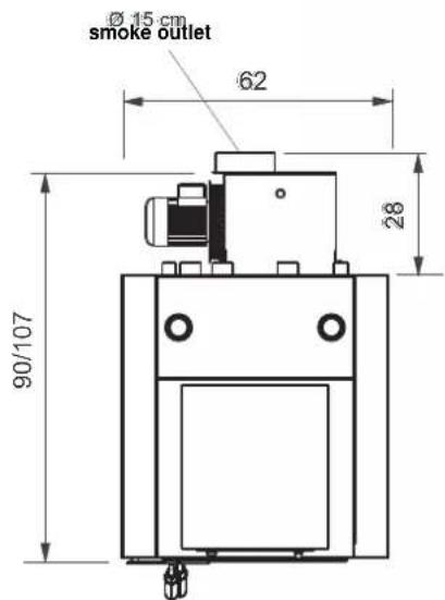
measurements in cm
INSTALLATION
WARNINGS
Boiler installation must take place in compliance with local regulations, including those with reference to national and European standards.
- The boiler must only be used for its intended use. Any other use is considered improper and dangerous.
- The boiler was designed to heat water. Any other use of liquids other than water is considered improper and dangerous.
- The boiler was designed exclusively for installation inside suitable technical premises. Therefore it cannot be installed and work outside. Installation outside can cause malfunctions and danger.
- IT IS FORBIDDEN for children or people incapable of looking after themselves to use the boiler.
- IT IS FORBIDDEN to change or alter the safety devices on the boiler.
- Do NOT leave packaging within reach of children or people incapable of looking after themselves.
- Do NOT touch the boiler if your feet are wet or damp.
- Do NOT plug or reduce the air vents in the boiler technical premises.
- Do NOT plug or reduce the air vents into the boiler.
- During operation, some elements of the boiler can reach high temperatures, therefore avoid coming in contact with them without having adequate protection.
- During operation, the door of the fi rebox MUST remain closed.
- The boiler was designed to work in any climatic condition, but in the event of adverse climatic conditions the safety systems may activate. Under no circumstances disable the safety devices.
- In the event of natural disasters, such as earthquakes, floods, etc. immediately switch off the boiler.
- In the event the boiler blocks, which was not caused by normal maintenance, call the support centre.
- The smoke vent and water drainage connections must be carried out by qualified people who can issue documentation in compliance with installation according to national standards.
- In Italy, you need to refer to the Declaration of Conformity in compliance with M.D. 37/2008 (previously L. 46/90) and according to the standards UNI 10683 and UNI 10412-2.
In the event of installation in apartment blocks, ask the administrator's opinion beforehand.
- The installation technician will illustrate functioning of the system.
First start-up (testing) must be carried out by the EDILKAMIN AUTHORISED TECHNICAL SUPPORT CENTRE (TSC) as stated in the standard UNI 10683.
This standard indicates the control operations to follow on site to ensure the system is working properly.
BOILER PREMISES
Before installing it, you can identify the point suitable for boiler positioning, checking that:
- The boiler to install is suitable for the type of system to insert it on.
- The premises has the requirements and characteristics to meet standards in force.
- There is sufficient combustion air flowing in the premises for regular combustion.
• Passage of tubing is possible for the heating system.
- The support surface has a suitable capacity to support the weight of the appliance. Otherwise, the support surface should be adequately modified before installation.
- The rear and side walls and the support flooring of the boiler should be created using fireproof materials or covered in protective material.
- You can easily create or position the chimney fl ue and the external air intake.
INSTALLATION
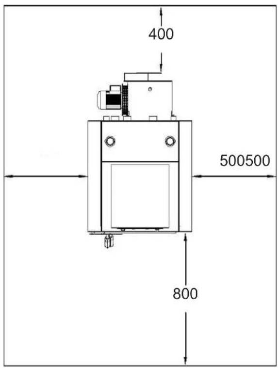
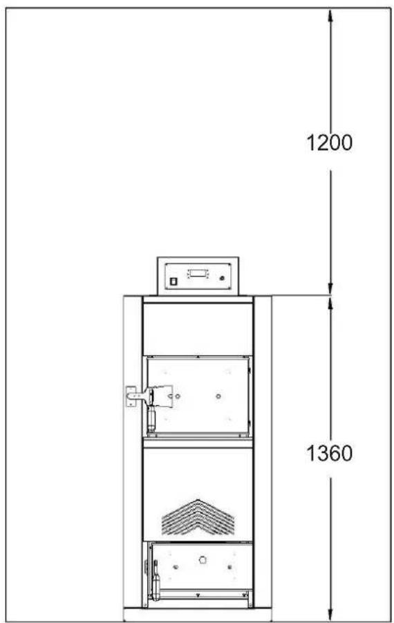
DISTANCES TO RESPECT IN PREMISES
The boiler was designed for installation at safe distances from objects and walls.
- Minimum distance in front of the boiler must be 800 mm to guarantee correct opening of the door and normal maintenance operations.
- Minimum distance permitted between the rear and a wall must be 400 mm.
- Minimum distance between the boiler and the side walls must be 500 mm.
- Minimum distance between the boiler and the upper walls must be 1200 mm.
INSTALLATION
AIR INTAKE
The combustion air intake must be created on the bottom of an outer wall and have a section of at least 250~cm^2 .
The protective grill must be closed.
The air intake must not open towards premises with potentially pollutant air in garages or warehouses.
Ensure the air intake is not blocked in any way.
CONNECTION TO CHIMNEY FLUE
The boiler works with forced draft, therefore the smoke extractor emits combustion air inside the chamber to enable combustion. It is therefore necessary to guarantee correct evacuation of the smoke connecting the boiler to a smoke flue that guarantees natural draft.
For connection to a smoke fl ue, local and national standards must be complied with.
A smoke fl ue must meet the following requirements:
- It must be in waterproof material and resistant to the temperature of the smoke and relevant condensate.
- It must have sufficient mechanical strength and weak thermal conductivity.
- It must be perfectly sealed to avoid cooling of the flue.
- Its progression must be as vertical as possible.
- It must be adequately distanced from combustible or fl ammable materials using air cavities or appropriate insulation.
- New or old chimneys built without compliance with specifications should be recovered by piping the chimney. You should therefore introduce a metal flue inside the existing chimney and fill with adequate insulation.
- The chimney fl ue must have a piping diameter of no less than the boiler outlet joint.
- There must be a preferably circular internal section; the square or rectangular section must have rounded corners with a radius of no less than 20 mm.
- It must have a constant, free, independent, and no choking internal section.
-
The smoke tubes must not cross premises in which installation of the combustion appliances is forbidden.
-
Flexible tubing is not allowed.
- A "T" tube must be installed immediately after the boiler outlet to periodically clean residue.
- A collective smoke pipe cannot be used.

- Only outlet pipes must be used suitable for the fuel used.
- Correct implementation of the smoke pipe allows, in the event of a power cut, normal smoke flow outwards.
- Avoid creating completely horizontal sections.
- An extractor hood must not be in the premises where the boiler is installed.
- Direct discharge on the wall is not permitted.
- Given the low temperatures of the smoke when the boiler is fully operational, the discharge channels must be created in suitable material to resist combustion products and their possible condensate.
• Install an inspection valve to enable drainage of any condensate formed. - Use a rain-proof and wind-proof terminal.
- You need to place one or more measurement points for sealed and/or auto-locking combustion analysis.
- You are advised to check emissions after installation.
- Draft must be guaranteed of 12 Pa.
- It must not be installed in the same premises as other heating appliances.
INSTALLATION
CHIMNEY STACK
The chimney stack must have the following requirements:
• have a section and shape equivalent to that of the chimney fl ue;
- have a useful outlet section no less than double that of the chimney fl ue;
- be built to prevent rain, snow or foreign body penetration and, for wind, guarantee normal smoke flow;
- it must be positioned to guarantee adequate dispersion and dilution of combustion products, outside the back flow zone.

CHIMNEY HEIGHT
The height of the part of the chimney protruding from the roof depends on the type of slope, its inclination and its position.
FLAT ROOF
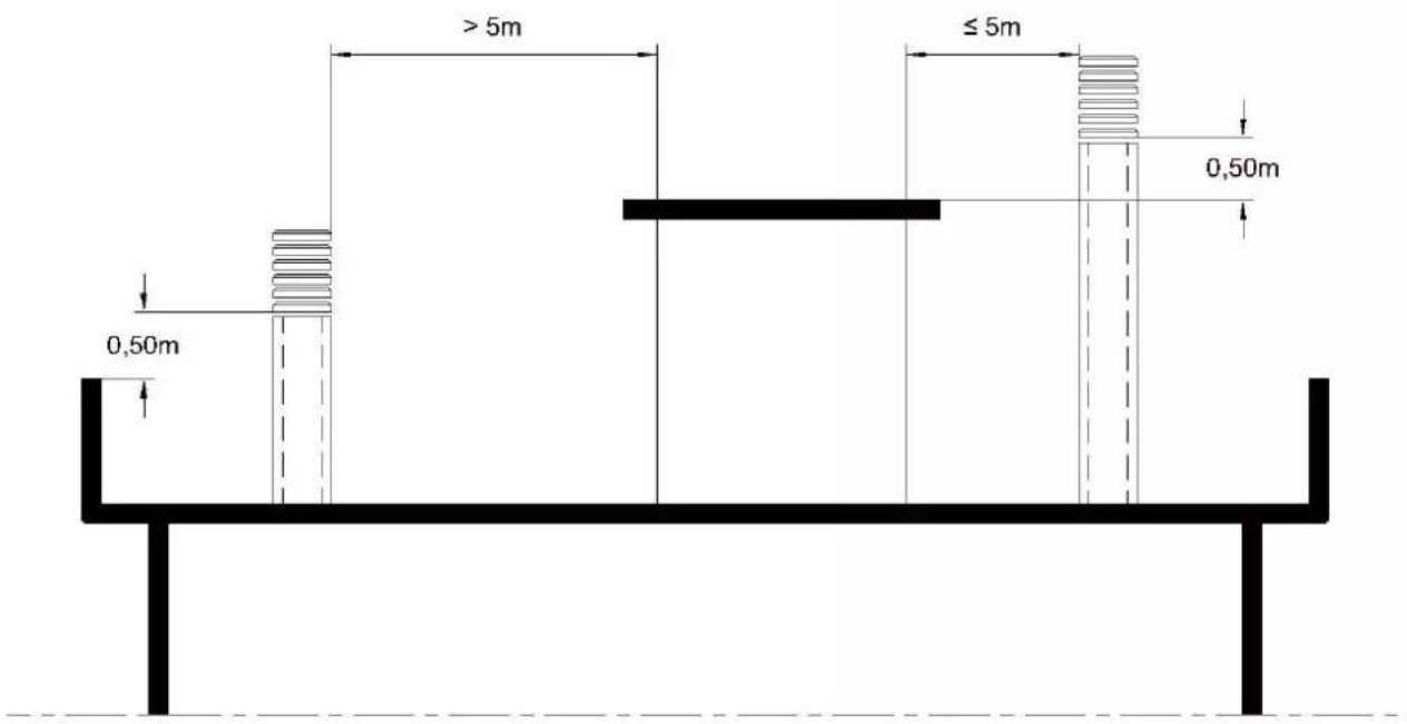
INSTALLATION
SLOPED ROOF
| ROOF SLOPE BACKFLOWZONE | DISTANCE BETWEEN HIP AND CHIMNEY | MINIMUM CHIMNEY HEIGHT | |
| β m | A | H | |
| 15° 0.50 m | ≤ 1.85 m 0.50 m over hip | ||
| > 1.85 m 1.00 m from roof | |||
| 30° 0.80 m | ≤ 1.30 m 0.50 m over hip | ||
| > 1.30 m 1.20 m from roof | |||
| 45° 1.50 m | ≤ 1.50 m 0.50 m over hip | ||
| > 1.50 m 2.00 m from roof | |||
| 60° 2.10 m | ≤ 1.20 m 0.50 m over hip | ||
| > 1.20 m 2.60 m from roof | |||
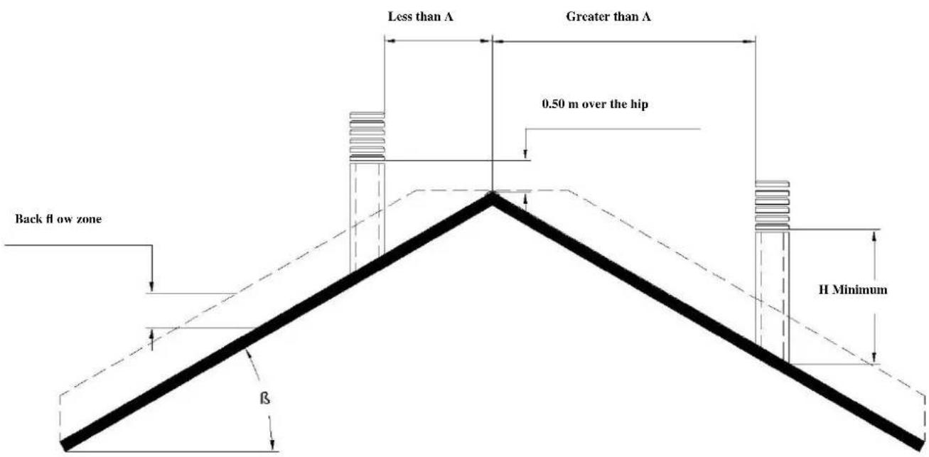
ROOF VENT WITH STEEL CHIMNEY FLUE
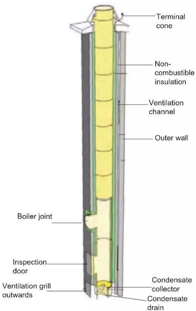
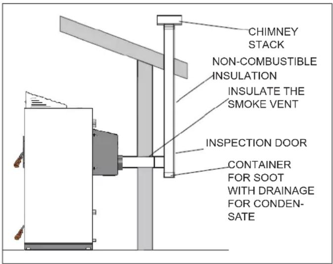
In installation of the chimney flue, always guarantee an inspection door to enable periodic cleaning of soot and a condensate collector with drainage to evacuate any condensate.
If the smoke pipe is installed completely externally, you should make it fully in stainless steel with a double wall to guarantee better resistance to atmospheric agents and adequate temperature of the smoke vent.
INSTALLATION
ROOF VENT WITH STEEL CHIMNEY FLUE
In installation of the chimney fl ue, always guarantee an inspection door to enable periodic cleaning of soot and a condensate collector with drainage to evacuate any condensate. If the smoke pipe is installed completely externally, you should make it fully in stainless steel with a double wall to guarantee better resistance to atmospheric agents and adequate temperature of the smoke vent.
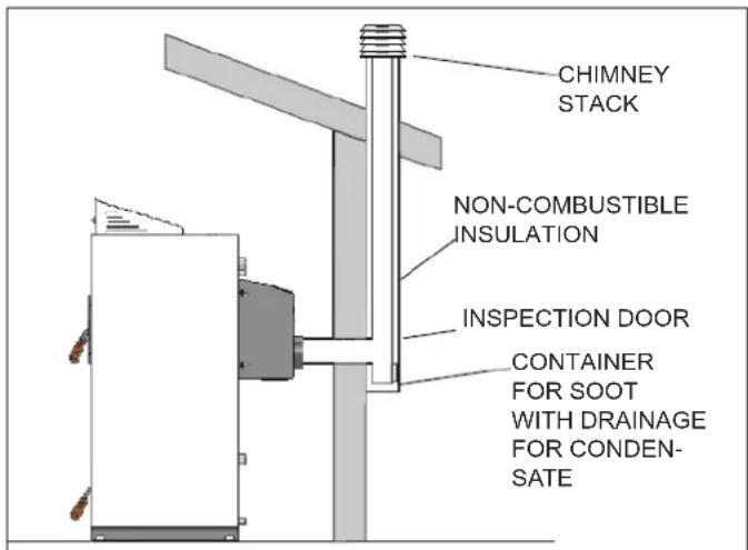
ROOF VENT WITH TRADITIONAL CHIMNEY FLUE
Combustion gas can also be evacuated using an existing, traditional chimney fl ue provided it is built to standard.
It must comply with the following regulations:
- it must be equipped with adequate insulation in the exposed external section;
- the internal section must be constant;
- it must be created using material resistant to high temperatures, the action of combustion products and any condensate that could form;
- mainly vertical progression with deviation from the axis not over 45^ ;
- it must have a soot and condensate collection chamber which can be inspected via a door.
HYDRAULIC CONNECTION
Correct dimensioning of the boiler and the heating system, as well as the choice of type of system to install are the tasks of the installation technician and/or planner.
If installation of the boiler includes integration with another pre-existing system using a gas, diesel, wood-burning boiler, it must be carried out by qualified staff who will issue documentation on correct installation according to the standards in force in each country (for example in Italy pursuant to M.D. 37/2008 and pursuant to the standard UNI 10412-2).

It is important to wash the entire system before connecting the boiler to eliminate deposits and residue in compliance with Standard UNI 8065 (water treatment in heating systems for residential use).
Install shut-off valves upstream of the boiler to insulate it from the rest of the system if any movement or maintenance operation is necessary.
With a closed hydraulic system circuit, working pressure must be between 1 and 2 bar and you need to install a thermal relief valve.
INSTALLATION
ANTI-CONDENSATE KIT OPTIONAL
For correct operation you need to install an anti-condensate mixer valve to guarantee adequate return temperature in the boiler to protect the boiler from condensate in the smoke pipes. The diagram includes use of accessories available on the EDILKAMIN pricelist.
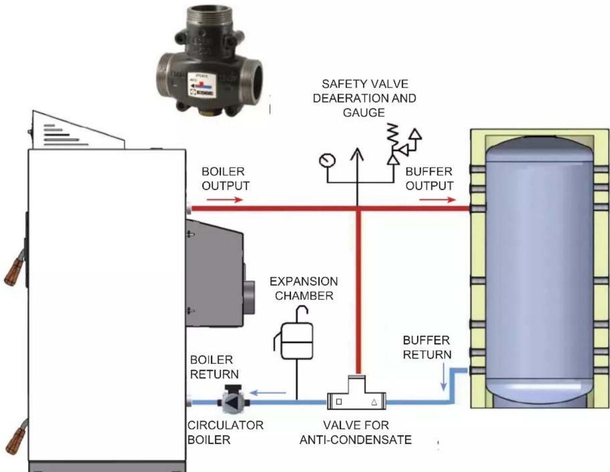
flowchart
graph TD
    A["Boiler OUTPUT"] --> B["Expansion Chamber"]
    B --> C["Valve for Anti-Condensate"]
    C --> D["CIRCULATOR BOILER"]
    D --> E["BOILER RETURN"]
    E --> F["SAFETY VALVE DEAERATION AND GUAGE"]
    F --> G["BUFFER OUTPUT"]
    G --> H["BUFFER RETURN"]
    H --> I["VALVE FOR ANTI-CONDENSATE"]
ANTI-CONDENSATE VALVE CHARACTERITIC BEND
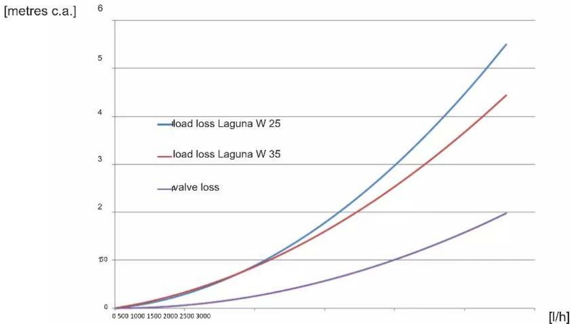
line
| [l/h] | load loss Laguna W 25 | load loss Laguna W 35 | valve loss | | ----- | --------------------- | --------------------- | ---------- | | 0 | 0 | 0 | 0 | | 1000 | ~5 | ~5 | ~2 | | 1500 | ~10 | ~10 | ~4 | | 2000 | ~15 | ~15 | ~6 | | 2500 | ~20 | ~20 | ~8 | | 3000 | ~25 | ~25 | ~10 | | 3500 | ~30 | ~30 | ~12 | | 4000 | ~35 | ~35 | ~14 | | 4500 | ~40 | ~40 | ~16 | | 5000 | ~45 | ~45 | ~18 | | 5500 | ~50 | ~50 | ~20 | | 6000 | ~55 | ~55 | ~22 |INSTALLATION
CORRECT DIMENSIONING ACCUMULATION
Installation of the boiler always includes connection to the system of an inertial accumulator (thermal fl ywheel), composed of an accumulation tank, with thermal insulation where the heated water circulates from the boiler.
This enables rapid absorption of increases or decreases in temperature, increasing the autonomy of the fully operational system.
In wood-burning boiler operation, the fuel cannot be measured, therefore once loaded it must be consumed in a single solution. When fully operational, in modulation, the minimum power supplied is greater than 30% of the nominal thermal power, therefore you need to install a correctly dimensioned inertial accumulator according to the following formula pursuant to Standard 303-5:
$$ \mathrm{Vsp} = 1 5 \times \mathrm{TB} \times \mathrm{QN} (1 - 0, 3 \mathrm{QH} / \mathrm{Qmin}) (\text { in litres }) $$
Where:
• Vsp is the accumulation volume in litres;
- QN is the nominal power of the boiler in kilowatts;
• TB is the combustion period in hours;
• QH is the average power required in kilowatts;
- Qmin is the minimum power of the boiler in kilowatts.
Therefore assuming:
• QN boiler nominal power = 26.9 kW;
• TB combustion period = 3 hours;
• QH average power required = 20 kW;
- Qmin minimum boiler power 50% nominal = 13.5 kW.
$$ \mathrm{Vsp} = 6 7 0 \text { litres } $$
SAFETY HEAT EXCHANGER FOR CLOSED CIRCULT OPERATION TO COMBINE WITH THERMAL RELIEF VALVE
The boiler is equipped with a safety heat exchanger to connect to a thermal relief valve which in the event of a power cut or circulator blockage acts as a protection device on the boiler to prevent overheating.
It is important to assemble the thermal relief safety valve (Watts STS20 type) so that, in fully operational mode, the safety heat exchanger is connected to the main lines of the pressurised mains water without any shut-off device on the water supply (shutter, valves).
The discharge side must flow without obstruction in a gutter or drain.
The temperature of the cold water permitted for the exchanger must be at least 10 ± 5^ with maximum pressure of 1.5 bar.
Note: The thermal relief valve must be installed before the system is loaded or operational.
INSTALLATION
Thermal relief valve operation:
The valve independent of the pressure, opens when the primary circuit temperature reaches approximately 95^ C. Valve opening leads to constant water drainage that prevents the temperature reaching 110^ C.

natural_image
Coiled stainless steel pressure relief valve with red adjustment knobs (no text or symbols visible)Note: you are advised to test the thermal drainage valve once installed by bringing the boiler to the valve opening temperature.
It is forbidden to produce sanitary hot water via the safety heat exchanger.
The exchange must be permanently connected to a thermal relief safety valve and must activate with maximum efficiency to cool the boiler in the event of an emergency.
Connection diagram
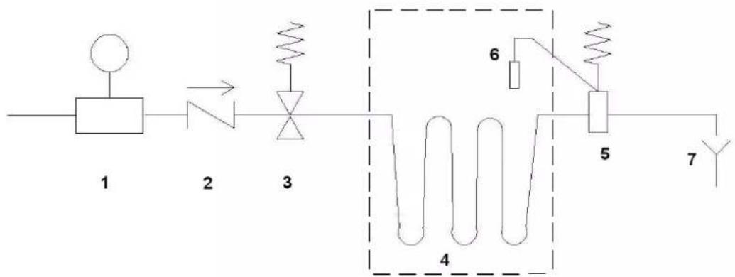
flowchart
graph LR
    A["Power Source"] --> B["Component 1"]
    B --> C["Switch 2"]
    C --> D["Diode 3"]
    D --> E["Solenoid Coil 4"]
    E --> F["Component 5"]
    F --> G["Y/Y Y"]
    E --> H["6"]
    H --> I["Resistor"]
    I --> J["Resistor 5"]
- Pressure reducer
- Check valve
- Safety valve
- Boiler inner safety coil
- Thermal relief valve
- Sensor
- Vent
INSTALLATION
SYSTEM DIAGRAMS
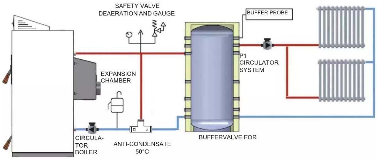
The system has 2 circulators:
Boiler Circulator enabling buffer loading. The circulator activates once the boiler temperature of 50^ C is reached and will always work until the differential between the boiler temperature and buffer temperature reach 5^ C.
PI System circulator allows management of heating system controlled by buffer. The circulator activates if the buffer temperature is over 50^ C.
ANTI-CONDENSATE VALVE ASSEMBLY
flowchart
graph TD
    A["Expansion Chamber"] --> B["CIRCULATOR BOILER"]
    B --> C["ANTI-CONDENSATE 50°C"]
    C --> D["BUFFERVALVE FOR"]
    D --> E["P1 CIRCULATOR SYSTEM"]
    E --> F["BUFFER PROBE"]
    G["SAFETY VALVE DEAERATION AND GAUGE"] --> H["Pressure Gauge"]
    I["Pressure Gauge"] --> J["Pressure Gauge"]
    K["Pressure Gauge"] --> L["Pressure Gauge"]
    M["Pressure Gauge"] --> N["Pressure Gauge"]
To connect the boiler circulator see the connections diagram on page 73.
The diagram includes use of accessories available on the EDILKAMIN pricelist. Loose parts are also available from local dealers (exchanger, valves, etc.),
INSTRUCTIONS FOR USE
SYNOPTIC PANEL
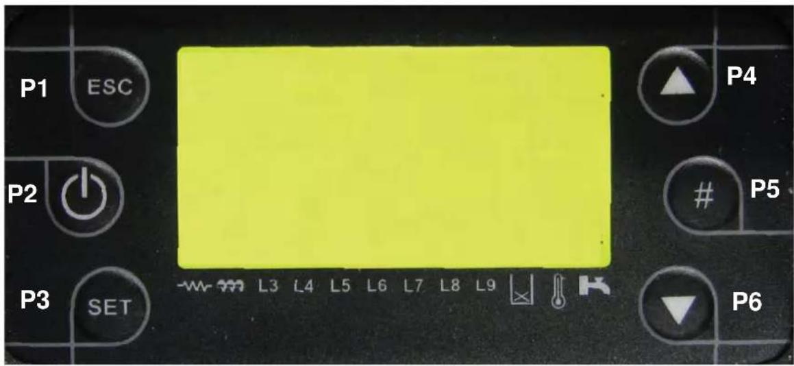
| P1 Esc exit key NOT USED | ||
| P2 ON/OFF or unlock key NOT USED | ||
| P3 Menu key for adjustments L3 Boiler circulator light | ||
| P4 Menu scrolling key L4 System circulator light | ||
| P5 Keypad lock key L5-L9 NOT USED | ||
| P6 Menu scrolling key Open thermostat contact | ||
DISPLAY
MAIN SCREEN
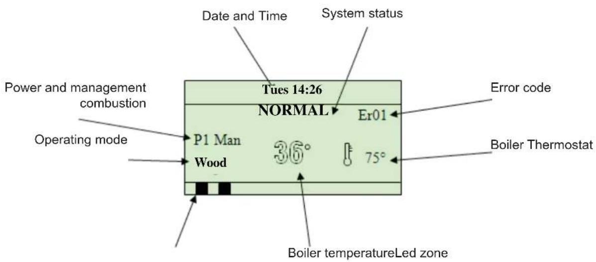
SECONDARY SCREENS
On pressing keys P4/P6 you can display:
T. Smoke - Smoke temperature [°C]
T. Boiler - Boiler temperature [^ C]
T. Buffer - Buffer probe temperature [°C]
Pressure – Value not detected
INSTRUCTIONS FOR USE
KEYS USE
 | P1Esc (exit) function from menu or sub-menu. |
 | P2ON/OFF Switch on/off function pressing the key for 3 seconds up to acoustic signalUNLOCK System unlocking function after an error by pressing the key for 3 seconds up to the acoustic signal |
 | P3MENU Menu and sub-menu access functionCHANGE Access menu changes |
 | P4MENU SCROLL Scrolls the main and secondary screens upwards. In the menu scroll through the various sub-menus upwards |
 | P5NOT USED |
 | P6MENU SCROLL Scrolls the main and secondary screens downwards. In the menu scroll through the various sub-menus downwards |
ERRORS AND DISPLAYS
| DISPLAY DESCRIPTION | |
| Er01 Safety thermostat activation error | |
| Er04 Water excess temperature error | |
| Er05 Smoke excess temperature error | |
| Er11 Internal clock error | |
| Er15 No electrical power supply error | |
| Er16 Communication error with commands panel | |
| Er23 Boiler or buffer temperature probes error | |
| DISPLAY DESCRIPTION | |
| Probe Status display of temperature probes. Indicates the temperature read on one or more probes is equal to the maximum or minimum possible value | |
| Door Open wood load door | |
| Link Error No communication between the keypad and the control board |
INSTRUCTIONS FOR USE
USER MENU
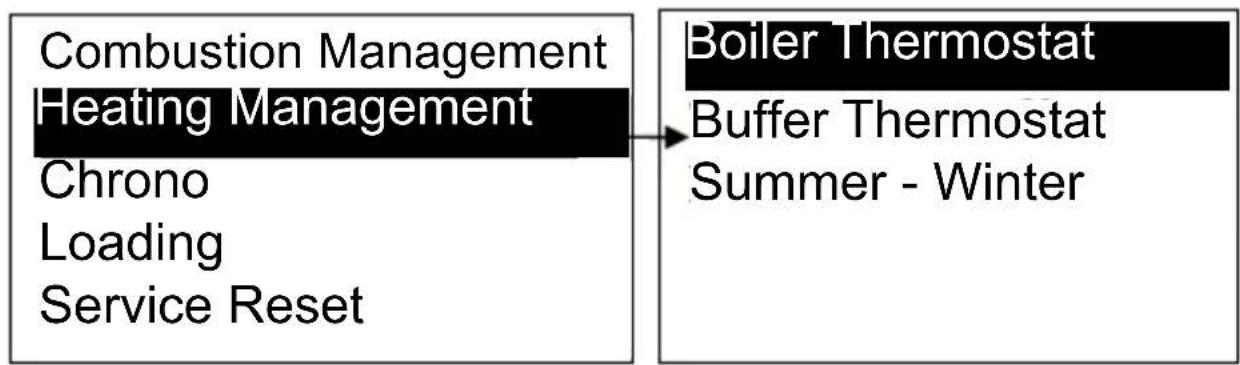
On pressing the

key you enter the fi rst screen on the menu
Combustion Management Heating Management
Chrono
Loading
Service Reset
By pressing the

and

key you scroll the menu highlighting the desired item.
Using the

key you can enter the sub-menu by obtaining the list or the parameter to change.
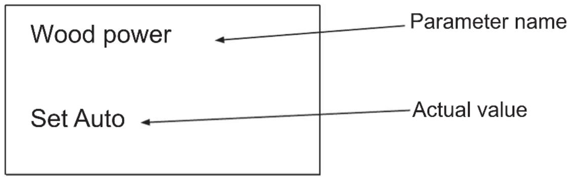
In the settings menu, there is the name of the parameter, the minimum, the maximum and the actual value (Set).
Pressing the

key you change the parameter and the Set field flashes and with the keys

and

you can increase or decrease the parameter.
Press the

key to confirm a new parameter is save, instead pressing
the

key you cancel the operator and restore the previous data.
Pressing it again, you exit and return to the previous screen.
Note: after 60 seconds without pressing the keys, the system automatically exits the menu.
| USER MENU DESCRIPTION | ||
| Combustion Management | Wood power It displays the combustion power of the system | |
| Heating Management | Boiler Thermostat Menu to change the boiler thermostat | |
| Buffer Thermostat Menu to change the buffer thermostat | ||
| Summer-Winter Summer or Winter selection mode | ||
| Chrono NOT USED | ||
| Loading NOT USED | ||
| Reset Service Menu to reset the System Maintenance FunctionMessage | ||
INSTRUCTIONS FOR USE
COMBUSTION MANAGEMENT MENU
Menu to change the system combustion parameters. It is composed of some sub-menus.
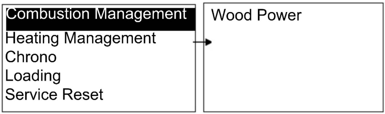
flowchart
graph LR
    A["Combustion Management"] --> B["Heating Management"]
    A --> C["Chrono"]
    A --> D["Loading"]
    A --> E["Service Reset"]
    F["Wood Power"] --> G
WOOD POWER
Menu consisting of displaying the system combustion power.
It is set as standard in automatic mode.
| Combustion Description | |
| Auto Power regulated | in automatic mode by system |
flowchart
graph LR
    A["Wood power"] --> B["Parameter name"]
    C["Set Auto"] <--_D["Actual value"]
INSTRUCTIONS FOR USE
HEATING MANAGEMENT MENU
Menu to change the system heating parameters. It is composed of some sub-menus.
flowchart
graph LR
    A["Combustion Management"] --> B["Heating Management"]
    C["Chrono"] --> D["Loading"]
    E["Service Reset"] --> F["Boiler Thermostat"]
    G["Buffer Thermostat"] --> H["Summer - Winter"]
BOILER THERMOSTAT
Menu to change the value of the boiler thermostat settable from a minimum of 50^ C to a maximum of 80^ C.
BUFFER THERMOSTAT
Menu to change the buffer thermostat value for the heating function.
MENU RESET SERVICE
Menu that enables resetting of the System Maintenance Function (see page 76).
PERSONALISATIONS MENU
To access the menu, press the key for 3 seconds

| PERSONALISATIONS MENU DESCRIPTION | ||
| Keypad Settings | Date and Time Time, day, date setting menu | |
| Language Menu to choose the language | ||
| Keypad Menu Adjust contrast Menu to adjust display contrast | ||
| Adjust Minimum Light | Menu to adjust lighting on the display when the commands are not used | |
| Keypad Address Not used | ||
| Nodes List Displays the | board information and firmware | |
| Acoustic Alarm Activates/deactivates the acoustic alarm | ||
| System Menu Menu to access the Technical Menu, password protected | ||
KEYPAD SETTINGS
Menu to configure the date, time and language.
INSTRUCTIONS FOR USE
DATE AND TIME
Menu that allows setting of the date, time and day.
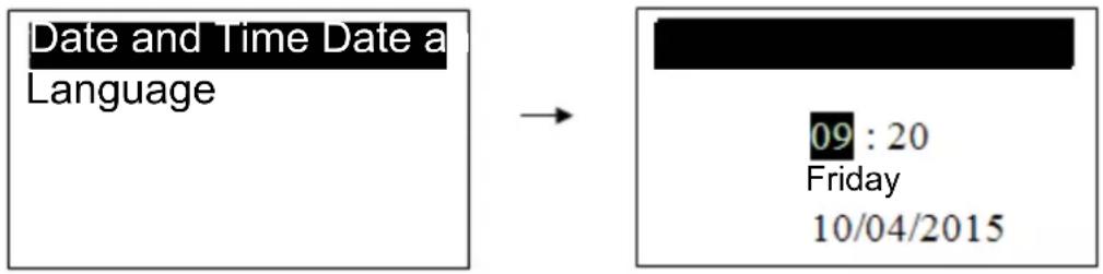
Press the ⚠ and ⚡ keys to select the hours, minutes or day of the week.
Press SET to enter the change, the cursor starts to flash.
Press and to change the value, then again SET to save the value,
lastly press ESC to return to the main menu.
LANGUAGE
Menu that changes the language on the commands panel. The language highlights the one currently set.
KEYPAD MENU
Menu that allows setting of contrast, minimum lighting of the display and the acoustic alarm.
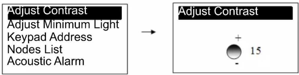
ADJUST CONTRAST
Adjusts display contrast
flowchart
graph LR
    A["Adjust Contrast\nAdjust Minimum Light\nKeypad Address\nNodes List\nAcoustic Alarm"] --> B["Adjust Contrast"]
    B --> C["+ 15"]
    B --> D["-"]
Adjusts lighting on the display when the commands are not used
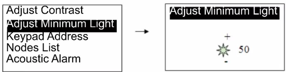
flowchart
graph LR
    A["Adjust Contrast\nAdjust Minimum Light\nKeypad Address\nNodes List\nAcoustic Alarm"] --> B["Adjust Minimum Light"]
    B --> C["+ 50 -"]
NODES LIST
The window displays information on the board: fi rmware, type.
ACOUSTIC ALARM
Allows activation or deactivation of the acoustic alarm.
INSTRUCTIONS FOR USE
WARNINGS BEFORE START-UP
• Installation exclusively includes connection to a chimney flue. For any complex and articulated installation, contact the authorised EDILKAMIN Technical Support Centre (TSC).
- Other types of installations are not advised from those for which the boiler was intended.
- Ensure the hydraulic system is perfectly sealed and does not have any water leaks or pressure drops.
- Ensure the shut-off valves on the system are open.
- Ensure all the air inside the system is purged.
- Ensure there are no obstructions on the chimney flue and combustion air inlet.
- Ensure pressure in the circuit is at least 1.0 bar, for installations in a closed circuit.
- Ensure the thermal relief valve is connected.
- Ensure the fuel is dry and not damp.
- Ensure the fuel is suitable for the boiler.
- Ensure the combustion chamber is free and clean.
- Ensure the flame catalyser is positioned correctly.
- Check the electrical connection (230 V – 50 Hz) and power the boiler.
- Check the display is lighting on the command panel.
FUNCTIONING CONCEPT
Below, 7 stages of system functioning are listed.
| 1 OFF |
| 2 NORMAL |
| 3 MODULATION |
| 4 STAND BY (MAINTAINING) |
| 5 SAFETY |
| 6 SWITCH OFF |
| 7 BLOCK |
The system guarantees reading of the statuses of the SAFETY DEVICES and ALARMS in each functioning phase.
FIRST START-UP
ATTENTION: first start-up should be carried out by an authorised EDILKAMIN Technical Support Centre (TSC) which will check:
- all the standards already mentioned and the standards in force in the installation location were applied;
- correct installation of the boiler and the chimney fl ue;
- that there is no danger for the boiler and the installation environment.
IMPORTANT
The manufacturer cannot be held liable for poor functioning of the boiler or any damage caused by it to people or property if:
- fi rst start-up was not carried out in compliance with the above;
- boiler installation was not carried out perfectly in compliance with standards;
- installation of the system was carried out without complying with the standards in force.
The manufacturer declines any disputes or complaints if the standards for good functioning of the boiler are not complied with.
INSTRUCTIONS FOR USE
START-UP
- use the general switch on the left of the electronic panel putting it in position I;
|
0
- press the ON key

• From the OFF status, bring the boiler to NORMAL.
• The extractor fan starts at the speed set;
| Tues 9:36 | ||
| NORMAL | ||
| P1 Man Wood | 24° | 80° |
- open the wood storage loading door checking the lower door of the combustion chamber is closed properly;
- on the refractory floor place a small amount of wood cut into small pieces and place over the paper or some firelighters or another material that encourages switch on. Do not use flammable liquids;
-
close the loading door of the wood storage;
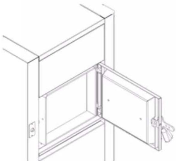
• with the wood well lighting, open the storage loading door and load the wood in two ways: -
arranging it correctly, up to the upper limit in the loading chamber;
-
arranging it up to half the chamber without exceeding the limit on the loading door.
natural_image
Line drawing of a door opening with a handle, showing internal structure and mounting bracket (no text or symbols)INSTRUCTIONS FOR USE
After a few minutes, open the door and check if the wood is lighting properly
Ensure this condition.
Attention: switch on is not permitted in the absence of alarms.
IMPORTANT: when on, the lower door can never be opened.
The upper loading door must be opened only to check the wood storage and to load it.
At the time of opening, release the handle by opening it a few centimetres and wait a few seconds before opening it completely, to ensure the fan reaches the maximum speed.
Only keep the door open for the time strictly necessary for wood loading.
Close the door tightly.
N.B. The loading door should never be left open during normal boiler operation, but only to carry out the aforementioned operations.
USEFUL ADVICE
In daily management of the boiler, before proceeding with switch on, check each day that inside the wood storage an excess quantity has not deposited of ash which can disturb good boiler operation. In this case, you need to make the ash fall through the central opening with the help of a tool.
Check the opening is always open before proceeding to switch on.
Open the lower door of the combustion chamber and remove the ash with the help of a pallet.
Only having carried out these simple, but important operations proceed to switch on.
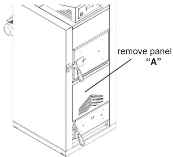
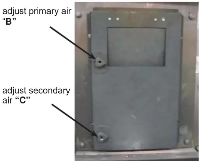
AIR ADJUSTMENTS
Removing the panel (A), between the two doors, you can adjust the quantity of air for combustion, based on the type of wood used, using the knobs (B) and (C).
If the wood has low humidity, simply adjust the knob (B), to the minimum or to the maximum (B) if humidity is high.
INSTRUCTIONS FOR USE
COMBUSTION
Once the boiler is lighting and having checked the presence of the flame, you can check the actual operation by reading the temperature values detected by the probes.
The boiler is in NORMAL functioning mode.
The boiler exits NORMAL status if one of these conditions occurs:
- the temperature of the smoke is under 60^ and a timer starts at 50 minutes: if the temperature stays over 60^ the timer resets, otherwise after the 40 minutes are up the boiler sets to OFF;
- the temperature of the smoke exceeds 160^ and passes to MODULATION;
- the temperature of the smoke exceeds 250^ and passes to SAFETY;
- the temperature of the boiler exceeds "Boiler Thermostat" and passes to MODULATION;
- the temperature of the buffer exceeds the "Buffer Thermostat" and passes to STAND BY once 2 minutes are up;
- the temperature of the boiler exceeds the safe temperature of 90^ and passes to SAFETY;
The MODULATION status has the purpose of reducing combustion trying to get the boiler to gradually reach the "Boiler Thermostat" set.
The boiler exits MODULATION status if one of these conditions occurs:
- the temperature of the smoke exceeds 250^ and passes to SAFETY;
- the temperature of the boiler exceeds the safety thermostat of 90^ and passes to SAFETY;
- the temperature of the smoke goes under 160^ and passes to NORMAL;
- the temperature of the boiler goes under "Boiler Thermostat" and passes to NORMAL;
- the temperature of the buffer exceeds the "Buffer Thermostat" and passes to STAND BY once 2 minutes are up;
- the temperature of the boiler exceeds the "Boiler Thermostat" + 5°C and passes to STAND BY once 2 minutes are up;
The STAND BY status has the purpose of keeping combustion active inside the boiler.
Using the wash cycles of the combustion chamber, you can drastically reduce combustion to avoid sending the boiler in SAFE mode, guaranteeing however the embers are maintained for subsequent switch on.
The cycles have a pause of 60 seconds, during which time the fan is stopped, and then works for 15 seconds during which time the fan works at full speed.
When the conditions that have lead the system to STAND BY no longer exist, the boiler goes to NORMAL with a delay of 60 seconds.
In SAFE status, the extractor fan is deactivated to keep the system safe. When the conditions that have lead the system to SAFE mode no longer exist, the system goes to the previous status.
INSTRUCTIONS FOR USE
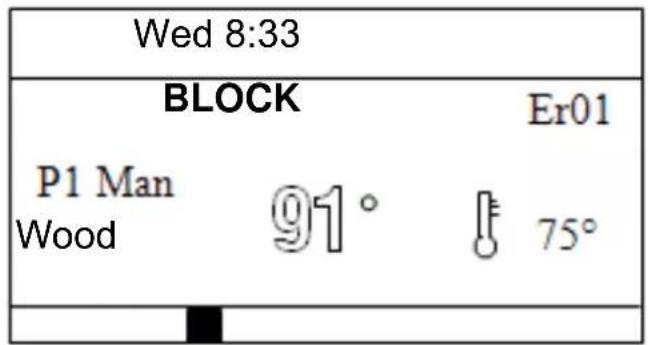
LOCK STATUS
This status is present during boiler operation or also with the system off if one of the errors among those described on page 73 occurs.
To reset the system lock status, you need to:
- solve the error that occurred (e.g. safety thermostat activation on boiler temperature reset).
- if the alarms are no longer present, press the ⏻ key for 3 seconds and the system switches OFF.
INSTRUCTIONS FOR USE
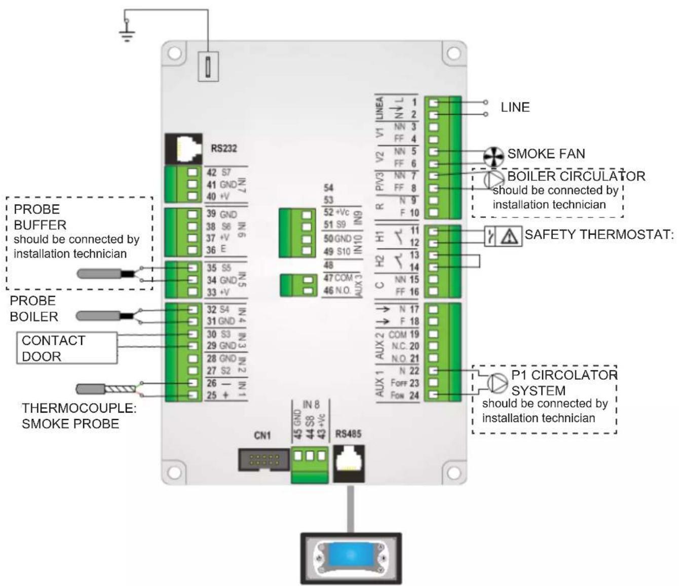
CONNECTIONS DIAGRAM
SYNOPTIC PANEL
INSTRUCTIONS FOR USE
The boiler is equipped with the following safety devices:
• SAFETY EXCHANGER
Connected to a thermal relief valve, it keeps the temperature under 110^ C in the event of an emergency.
• WATER BULB THERMOSTAT
Checks the temperature of the water inside the boiler. If the temperature exceeds the limit of 90^ C it shuts off the fan and stops combustion.
• WATER TEMPERATURE PROBE
If the temperature reaches the thermostat value, the boiler switches off or goes into stand-by.
- NO SWITCH ON
If during the switch-on phase the wood-burning boiler does not reach the smoke temperature of at least 60^ C in 40 minutes the boiler turns Off.
• ELECTRICAL SAFETY
The boiler is equipped with a fuse to protect the electronics.
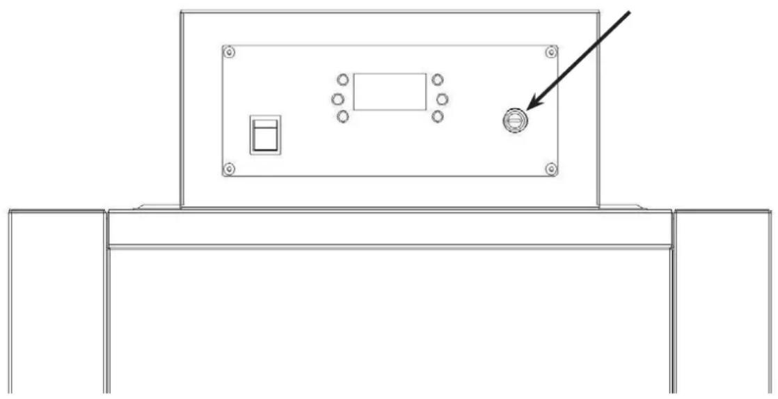
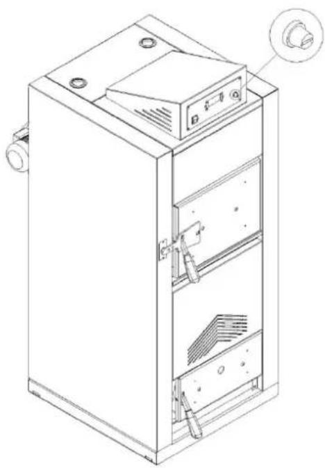
RE-ACTIVATION OF THE RESET THERMOSTAT
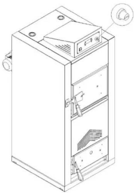
To re-activate the reset thermostat, unscrew the black hood and fully press the small cylinder until you hear a release click.
To intervene on the water bulb safety thermostat, contact the Technical Support Centre authorised by EDILKAMIN (TSC) to check the cause.
natural_image
Technical line drawing of a mechanical component with mounting base and control panel (no text or symbols)INSTRUCTIONS FOR USE
SAFETY DEVICES POSITIONING
natural_image
Technical line drawing of a cabinet with internal compartments and mounting holes (no text or symbols)Position of manual reset safety thermostat
1/2 "G F connections
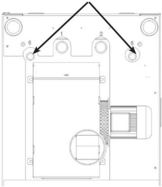
Position of safety exchanger and temperature control probe well connections
natural_image
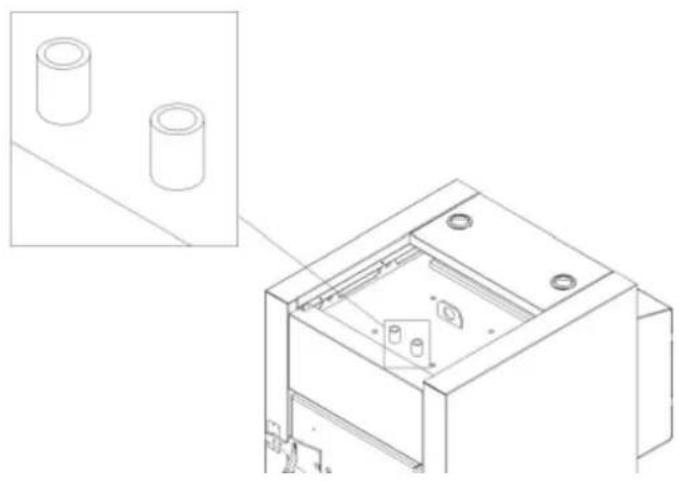
Technical line drawing of a mechanical housing or enclosure with two cylindrical components and internal components (no text or symbols)12 " G F control probe insertion position

- Maintenance and inspections carried out to standard and with regular intervals as well as only using original spare parts are fundamental for correct, problem and anomaly-free operation, guaranteeing a long boiler life.
- Maintenance is compulsory and must be regularly carried out periodically.
- Maintenance and inspections not carried out can cause damage to property and people.
- The inspection is necessary to determine the actual status of the boiler and compare it with the original status.
- Maintenance is necessary to bring the boiler to the original conditions status.
- As a result, maintenance should involve cleaning, setting or replacing worn parts.
- At the end of each heating season, you need to inspect the boiler to maintain the characteristics and efficiency of the entire system unchanged.
• After each cleaning procedure, the boiler must be checked to ensure everything moved or removed during maintenance is correctly re-positioned. - At the end of each season, you are advised to carry out in-depth cleaning of the boiler since the mineral ash can be a corrosive agent and reduce boiler reliability.
MANUAL CLEANING
Boiler cleaning must take place with the boiler cold, as follows:
- cut electrical current placing the main switch on the control panel to position 0;
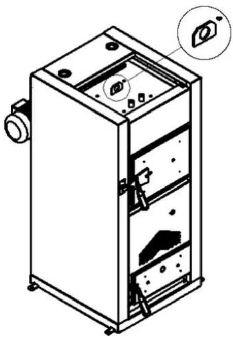
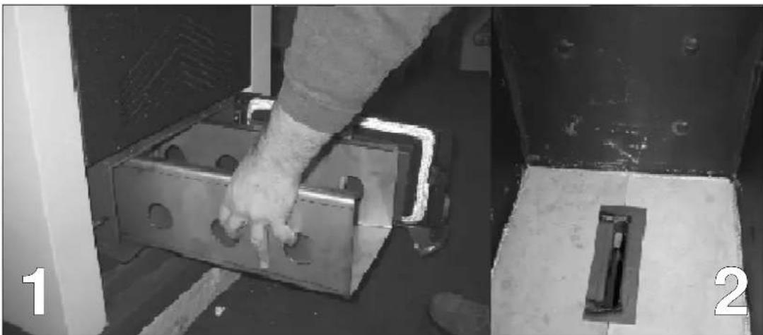
- open the lower door and carefully remove the catalyser in the combustion chamber by removing it, moving it forward (Fig. 1);
- clean the wood chamber by removing all the ash deposited and carefully give the combustion chamber an in-depth clean to remove all the deposits (Fig. 2);
- put the catalyser back inside the combustion chamber, paying attention that it is fully resting and placed at the centre of the chamber;
- remove the upper, rear cover on the boiler (Fig. 3) (should be carried out by the TSC
- Technical Support Centre authorised by Edilkamin);
- unscrew the two screws blocking the door of the smoke container and proceed to clean inside the smoke box;
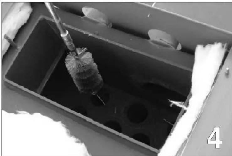
• delicately remove the smoke retarder inside the piping, using a tool if needed to do so; - use a steel brush supplied to clean the tube bundle (Fig. 4) (this should be carried out by the TSC - Technical Support Centre authorised by Edilkamin);
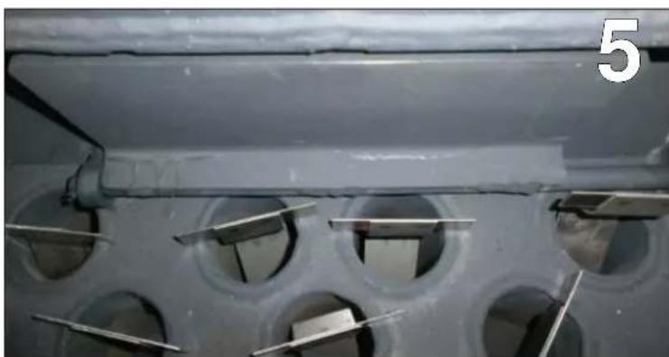
- clean the mobile shutter of any scale (Fig. 5) (this should be carried out by the TSC - Technical Support Centre authorised by Edilkamin).
You are advised to clean the "T" tube on the smoke channel every month.
NOTE:
on reaching 200 working hours, the display will show the writing "CLEAN".
The boiler will continue to work, but the client is invited to carry out accurate maintenance within his/her capabilities.
To eliminate the writing on the display, having carried out maintenance, press the “#” key.
MAINTENANCE
natural_image
Close-up of a metal bracket being inserted into a concrete block, with no visible text or symbols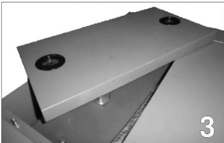
natural_image
Close-up of a metallic mechanical component with two circular holes and a base plate, no visible text or symbols.(should be carried out by the TSC - Technical Support Centre authorised by Edilkamin);
natural_image
Close-up of a brush cleaning or cleaning process inside a rectangular container with circular holes (no text or symbols visible)(should be carried out by the TSC - Technical Support Centre authorised by Edilkamin); (should be carried out by the TSC - Technical Support Centre authorised by Edilkamin);
natural_image
Close-up of a metallic mechanical component with circular holes and a central rod, no visible text or symbolsMAINTENANCE
COMPONENTS CHECK AND SCHEDULED MAINTENANCE
Each season you must call the Technical Support Centre authorised by EDILKAMIN (TSC) for the necessary seasonal maintenance.
It consists of:
- Cleaning the stove internally and externally
- Accurate cleaning of the exchange piping
- Accurate cleaning and scale removal of the burner in the combustion chamber and wood loading chamber
- Mechanically checking the ranges and fastenings
- Smoke channel cleaning (gasket replacement on the piping) and the smoke extractor fan chamber
- Probe check
- Cleaning/checking the synoptic panel
- Visual inspection of the electrical cables, the connections and power supply cable
- Check and replacement, if necessary, of the door seal
• Functional testing: switch on and operation
The cleaning, control and/or maintenance operations to carry out are summarised below:
| USER Technical | Support Centre authorised by EDILKAMIN (TSC) | ||
| Every 3-4 days | Every month | Every season | |
| Combustion chamber and wood chamber (Fig. 1-2) | ● | ||
| Upper cover and tube bundle (Fig. 3-4-5) | ● | ||
| “T” shaped tube cleaning ● | |||
| Smoke by-pass shutter ● | |||
| Smoke pipe ● | |||
| Accurate cleaning of internal smoke circuit and smoke channel | ● | ||
| Seal testing ● | |||
| Functional testing ● | |||
PLACING OUT OF SERVICE (END OF SEASON)
At the end of each seasons, you are advised to deep clean each part of the boiler.
You are advised to disconnect the appliance from the electrical power mains.
POSSIBLE TROUBLESHOOTING

- Attention, all repairs must only be carried out by the Technical Support Centre authorised by EDILKAMIN (TSC)
- Only original spare parts must be used.
- The manufacturer cannot be held in any way liable and the warranty expires if all the operations described below are not complied with and carried out correctly.
INDICATION OF POSSIBLE CAUSES OF MALFUNCTION INSTRUCTIONS AND SOLUTIONS
| SIGNALLING PROBLEM ACTIONS | ||
| Er01 Water | high temperature blockActivates if the water reading probereads a temperature over 90°C | Check the circulator is working properly (TSC)Check the plumbing (TSC)Re-activate the reset thermostat (User) |
| Er04 Water | excess temperature errorWater temperature too high in boiler | Check the plumbing (TSC) |
| Er05 Smoke | high temperature blockswitch off due to excessive smoke temperature | Check the smoke probe (TSC)Clean the exchangers (TSC)Excessive temperature of smoke can depend on: smoke extraction anomaly, blocked channel, improper installation, no air intake in premises(TSC). |
| Er11 Internal clock error Replace the battery on the electronic board (TSC)Remember it is a part subject to regular wear and therefore not covered by warranty. | ||
| Er15 No mains block(not a defect of the boiler).No electrical power for more than 50 minutes. | Check the electrical connection and drops in voltage (User) | |
| Er16 Error RS485Communication error between the control board and the display | Cut power from the boiler, wait a few minutes and then power again (User) | |
| Er23 Boiler | or buffer temperature probes error | Check the probes and their connections (TSC). |
DEMOLITION AND DISPOSAL
The owner is responsible for demolition and disposal.
You must work in compliance with the environment and the standards in force in the country.
Scrap the boiler by firstly separating the electrical parts, then the battery on the board and lastly recycling the materials via the authorised, professional companies.
NOTES
DATE AND STAMP OF INSTALLATION TECHNICIAN
DATE AND STAMP OF TSC 1 ^ST START-UP
DATE AND TIME OF ANY INTERVENTION
DATE AND STAMP OF SEASONAL MAINTENANCE
DATE AND STAMP OF DEALER
DATE AND STAMP OF TSC
For further clarification or needs, visit our website www.edilkamin.com
NOTES:
Madame/Monsieur,
natural_image
Technical line drawing of a multi-tiered industrial machine with internal components and mounting holes (no text or symbols)INFORMATIONS GÉNÉRALES
DESCRIPTION DE LA MACHINE
natural_image
Pile of sliced dried root pieces, likely herbal medicine or herbal medicine (no text or symbols visible)INFORMATIONS GÉNÉRALES
AVERTISSEMENTS ET CONSEILS CONCERNANT LE COMBUSTIBLE
natural_image
Illustration of stacked wooden crates with a red X symbol crossed out (no text or symbols present)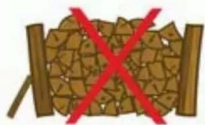
natural_image
Illustration of a wooden log with broken wood and two vertical bars, crossed out by a red X (no text or symbols)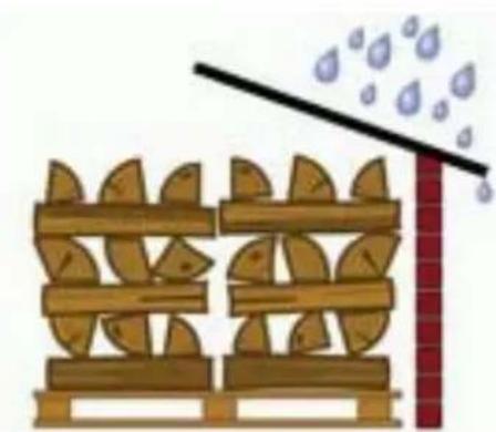
natural_image
Illustration of a wooden fence with leaf patterns and a red brick wall, no text or symbols presentINFORMATIONS GÉNÉRALES
DONNÉES TECHNIQUES
INSTALLATION
TOIT INCLINÉ
natural_image
Coiled stainless steel valve with attached metallic fittings (no text or symbols visible)natural_image
Technical line drawing of a door opening with internal components (no text or symbols)MODE D'EMPLOI
RÉACTIVATION THERMOSTAT AU RÉARMEMENT
natural_image
Technical line drawing of a mechanical component with mounting base and control panel (no text or symbols)MODE D'EMPLOI
POSITIONNEMENT DES DISPOSITIFS DE SÉCURITÉ
natural_image
Technical line drawing of a multi-level industrial machine cabinet with mounting holes and internal compartments (no text or labels)natural_image
Technical line drawing of a mechanical housing or enclosure with two cylindrical components and internal components (no text or symbols)natural_image
Close-up of a hand pressing a metal bracket component, with two views (labeled 1 and 2) showing close-up details (no text or symbols on the main subject)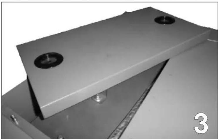
natural_image
Close-up of a metallic mechanical component with two circular holes and a base plate, no visible text or symbols.natural_image
Close-up of a brush cleaning or cleaning tool inside a rectangular container with circular holes (no text or symbols visible)natural_image
Close-up of a metallic mechanical component with circular holes and internal cutouts, no visible text or symbolsnatural_image
Technical line drawing of a multi-tiered industrial machine with internal components and mounting holes (no text or symbols)INFORMACIÓN GENERAL
natural_image
Pile of sliced dried root pieces, likely herbal medicine or herbal medicine (no text or symbols visible)INFORMACIÓN GENERAL
natural_image
Illustration of stacked wooden crates with a red 'X' symbol crossed out (no text or symbols present)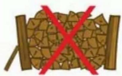
natural_image
Illustration of a wooden log with broken wood and red X symbol (no text or symbols)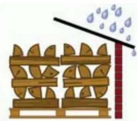
natural_image
Illustration of a wooden fence with leaf patterns and a diagonal line above a red brick wall, no text or symbols present.INFORMACIÓN GENERAL
DATOS TÉCNICOS
INSTALACIÓN
TECHO INCLINADO
natural_image
Coiled stainless steel pressure relief valve with attached metallic fittings (no text or symbols visible)T.Puffer – Temperatura sonda puffer [°C]
natural_image
Technical line drawing of a door opening with a handle, showing internal structure and mounting bracket (no text or symbols)INSTRUCCIONES DE USO
natural_image
Technical line drawing of a mechanical component with mounting holes and a control knob (no text or symbols)INSTRUCCIONES DE USO
natural_image
Technical line drawing of a multi-level industrial machine cabinet with mounting holes and internal compartments (no text or labels)natural_image
Technical line drawing of a mechanical housing or enclosure with two cylindrical components and internal components (no text or symbols)natural_image
Close-up of a metal bracket being installed, showing hand positioning and close-up details (no text or symbols visible)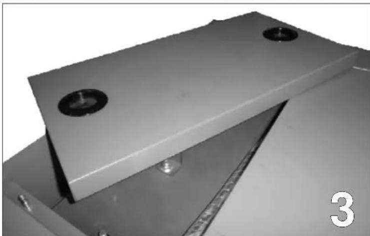
natural_image
Close-up of a metallic mechanical component with two circular holes and a base plate, no visible text or symbols.natural_image
Close-up of a brush cleaning or cleaning process inside a rectangular container with circular holes (no visible text or symbols)natural_image
Close-up of a metallic mechanical component with circular holes and metal fasteners, no visible text or symbolsnatural_image
Technical line drawing of a mechanical device with internal components and mounting features (no text or symbols)ALLGEMEINE INFORMATIONEN
natural_image
Pile of sliced dried root slices, likely herbal medicine or herbal medicine (no text or symbols visible)ALLGEMEINE INFORMATIONEN
natural_image
Illustration of stacked wooden crates with a red 'X' symbol crossed out (no text or symbols present)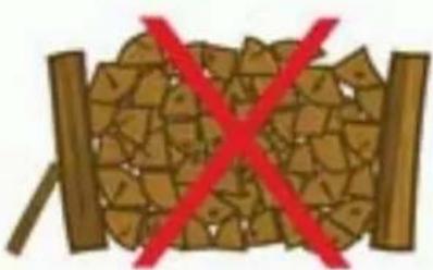
natural_image
Illustration of a wooden log with broken wood and two vertical bars, crossed out by a red X (no text or symbols)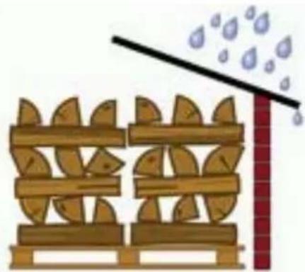
natural_image
Illustration of a wooden fence with leaf-shaped supports and a diagonal line above a brick wall, emitting blue droplets (no text or symbols)ALLGEMEINE INFORMATIONEN
TECHNISCHE DATEN
INSTALLATION
SCHRÄGDACH
natural_image
Coiled stainless steel pressure relief valve with attached metallic fittings (no text or symbols visible)natural_image
Technical line drawing of a door opening with internal components (no text or symbols)BEDIENUNGSANLEITUNG
natural_image
Technical line drawing of a device panel with mounting base and control buttons (no text or symbols)BEDIENUNGSANLEITUNG
natural_image
Technical line drawing of a multi-level industrial machine cabinet with mounting holes and internal compartments (no text or labels)natural_image
Technical line drawing of a mechanical housing or enclosure with two cylindrical components and internal components (no text or symbols)natural_image
Close-up of a metal bracket component being inserted, with hands visible and a close-up view of the part (no text or symbols)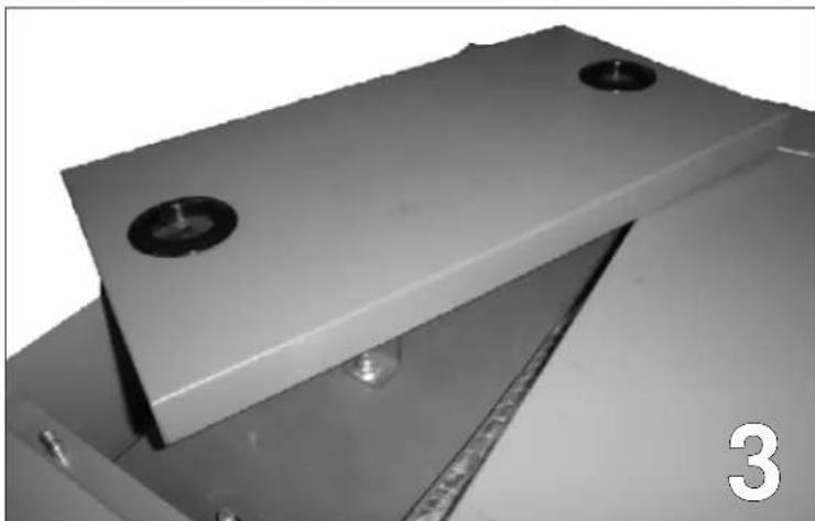
natural_image
Close-up of a metallic mechanical component with two circular holes and a base plate, no visible text or symbols.natural_image
Close-up of a brush cleaning tool in a rectangular container with circular holes (no text or symbols visible)natural_image
Close-up of a metallic mechanical component with circular holes and metal fasteners, no visible text or symbolsVERPAKKING EN TRANSPORT
natural_image
Technical line drawing of a multi-tiered industrial machine with internal components and mounting holes (no text or symbols)ALGEMENE INFORMATIE
BESCHRIJVING VAN DE MACHINE
natural_image
Pile of sliced dried root pieces, likely herbal medicine or herbal medicine (no text or symbols visible)ALGEMENE INFORMATIE
WAARSCHUWINGEN EN ADVIEZEN OVER DE BRANDSTOF
natural_image
Illustration of stacked wooden crates with a red 'X' symbol crossed out (no text or symbols present)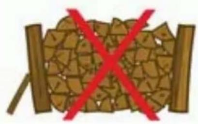
natural_image
Illustration of a wooden log with broken wood and red X marks (no text or symbols)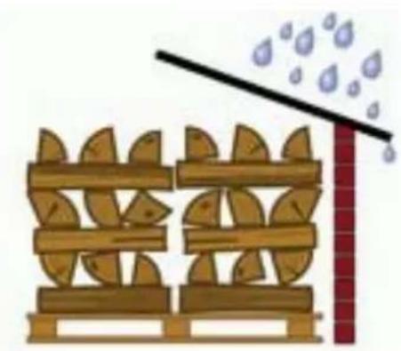
natural_image
Illustration of a wooden fence with leaf patterns and a diagonal line above a red brick wall, no text or symbols present.ALGEMENE INFORMATIE
TECHNISCHE GEGEVENS
INSTALLATIE
SCHUIN DAK
OPTIONELE ANTICONDENS KIT
natural_image
Coiled stainless steel pressure relief valve with a cylindrical terminal (no text or symbols visible)LIJST MET KNOOPPUNTEN
WAARSCHUWINGEN VOORAFGAAND AAN DE INSCHAKELING
CONCEPT VAN DE WERKING
natural_image
Technical line drawing of a door opening with internal components (no text or symbols)• THERMOSTAAT MET WATERBOL
REACTIVERING THERMOSTAAT MET HERSPANNING
natural_image
Technical line drawing of a mechanical component with mounting base and control panel (no text or symbols)natural_image
Technical line drawing of a multi-level industrial machine cabinet with mounting holes and internal compartments (no text or labels)natural_image
Technical line drawing of a mechanical housing or enclosure with two cylindrical components and internal components (no text or symbols)Kamer aanbrengen controle- meter 1/2" G F

natural_image
Close-up of a metal bracket component being inserted, with hands visible and a close-up view of the part (no text or symbols)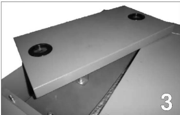
natural_image
Close-up of a metallic mechanical component with two circular holes and a base plate, no visible text or symbols.natural_image
Close-up of a cleaning tool applying material into a rectangular container with circular holes (no text or symbols visible)natural_image
Close-up of a metallic mechanical component with circular holes and a horizontal rod, no visible text or symbols
- INSTALLAZIONE
- AVVERTENZE
- ISTRUZIONI D'USO
- • MANCATA ACCENSIONE
- CONTENT
- SAFETY INFORMATION
- GENERAL WARNINGS FOR THE USER
- GENERAL INFORMATION
- PACKAGING AND TRANSPORT
- NOTE
- MACHINE DESCRIPTION
- The boiler is equipped with a:
- FUEL USED
- WARNINGS AND ADVICE ON FUEL
- CORRECT WOOD STORAGE
- N.B.:
- DIMENSIONS
- INSTALLATION
- WARNINGS
- BOILER PREMISES
- DISTANCES TO RESPECT IN PREMISES
- AIR INTAKE
- CONNECTION TO CHIMNEY FLUE
- CHIMNEY STACK
- CHIMNEY HEIGHT
- ROOF VENT WITH STEEL CHIMNEY FLUE
- ROOF VENT WITH TRADITIONAL CHIMNEY FLUE
- HYDRAULIC CONNECTION
- ANTI-CONDENSATE KIT OPTIONAL
- CORRECT DIMENSIONING ACCUMULATION
- Where:
- Therefore assuming:
- SAFETY HEAT EXCHANGER FOR CLOSED CIRCULT OPERATION TO COMBINE WITH THERMAL RELIEF VALVE
- Thermal relief valve operation:
- Connection diagram
- SYSTEM DIAGRAMS
- INSTRUCTIONS FOR USE
- P5
- DISPLAY
- SECONDARY SCREENS
- USER MENU
- Combustion Management Heating Management
- COMBUSTION MANAGEMENT MENU
- WOOD POWER
- HEATING MANAGEMENT MENU
- BOILER THERMOSTAT
- BUFFER THERMOSTAT
- MENU RESET SERVICE
- PERSONALISATIONS MENU
- KEYPAD SETTINGS
- DATE AND TIME
- LANGUAGE
- KEYPAD MENU
- ADJUST CONTRAST
- NODES LIST
- ACOUSTIC ALARM
- WARNINGS BEFORE START-UP
- FUNCTIONING CONCEPT
- FIRST START-UP
- IMPORTANT
- START-UP
- USEFUL ADVICE
- AIR ADJUSTMENTS
- COMBUSTION
- LOCK STATUS
- • SAFETY EXCHANGER
- • WATER BULB THERMOSTAT
- • WATER TEMPERATURE PROBE
- - NO SWITCH ON
- • ELECTRICAL SAFETY
- RE-ACTIVATION OF THE RESET THERMOSTAT
- SAFETY DEVICES POSITIONING
- MANUAL CLEANING
- NOTE:
- MAINTENANCE
- COMPONENTS CHECK AND SCHEDULED MAINTENANCE
- PLACING OUT OF SERVICE (END OF SEASON)
- POSSIBLE TROUBLESHOOTING
- DEMOLITION AND DISPOSAL
- NOTES
- INFORMATIONS GÉNÉRALES
- DESCRIPTION DE LA MACHINE
- AVERTISSEMENTS ET CONSEILS CONCERNANT LE COMBUSTIBLE
- MODE D'EMPLOI
- RÉACTIVATION THERMOSTAT AU RÉARMEMENT
- POSITIONNEMENT DES DISPOSITIFS DE SÉCURITÉ
- INFORMACIÓN GENERAL
- INSTALACIÓN
- INSTRUCCIONES DE USO
- ALLGEMEINE INFORMATIONEN
- BEDIENUNGSANLEITUNG
- VERPAKKING EN TRANSPORT
- ALGEMENE INFORMATIE
- BESCHRIJVING VAN DE MACHINE
- WAARSCHUWINGEN EN ADVIEZEN OVER DE BRANDSTOF
- INSTALLATIE
- OPTIONELE ANTICONDENS KIT
- LIJST MET KNOOPPUNTEN
- WAARSCHUWINGEN VOORAFGAAND AAN DE INSCHAKELING
- CONCEPT VAN DE WERKING
- • THERMOSTAAT MET WATERBOL
- REACTIVERING THERMOSTAAT MET HERSPANNING
Brand : EDILKAMIN
Model : LAGUNA W 25-35
Category : Boiler