45219 - Multimeter Wiha - Free user manual and instructions
Find the device manual for free 45219 Wiha in PDF.

User questions about 45219 Wiha
0 question about this device. Answer the ones you know or ask your own.
Ask a new question about this device
Download the instructions for your Multimeter in PDF format for free! Find your manual 45219 - Wiha and take your electronic device back in hand. On this page are published all the documents necessary for the use of your device. 45219 by Wiha.
USER MANUAL 45219 Wiha
up to 1,000 V AC, CAT IV
Order-No.: 45219

DE....3
EN....17
FR....31
NL....45
ES....59
IT....73
DA....87
NO....101
SV 115
Fl....129
PL....143
CS....157
RU....171
HU....185
Inhaltsverzeichnis
Introduction / scope of supply 19
Transport and storage 19
Safety references 19
Proper and intended use 20
Correctness of the operating instructions.... 21
Operation elements and connections 21
Clamp control and connection elements 21
Button functions 22
LCD segments....23
Power up options.... 23
User interface description 23
Measurements 23
Voltage measurement 23
Current measurement 24
Resistance measurement.... 24
Continuity test.... 25
Diode test 25
Capacitance measurement 25
Frequency measurement.... 25
NCV (non-contact voltage) measurement—AC only 26
Additional features....26
MAX/MIN 26
HOLD feature....26
Clamp meter backlight on/off 26
Clamp meter torch light on/off 26
APO feature 26
LPF feature (low pass filter) 26
Maintenance 27
Cleaning 27
Calibration Interval....27
Battery replacement.... 27
Technical data 28
Service and warranty....30
References marked on instrument or in instruction manual

Warning of a potential danger, follow with instruction manual.

Reference! Please use utmost attention.

Caution! Dangerous voltage. Danger of electrical shock.

Continuous double or reinforced insulation category II IEC 536 / DIN EN 61140.

Complies with EU specifications.

Complies with UK specifications.

Instrument fulfils the WEEE-Directive 2012/16/EU. This marking indicates that this product should not be disposed with other household wastes throughout the EU. To prevent possible harm to the environment or human health from uncontrolled waste disposal, recycle it responsibly to promote the sustainable reuse of material resources. To return your used device, please use the return and collection systems or contact the retailer where the product was purchased. They can take this product for environmentally safe recycling.
CAT IV 1000 V
Instrument complies to Measurement Category CAT IV 1000 V against earth.
Description:
Measurement Category CAT II is for measurements performed on circuits directly connected to the low voltage installation, i.e. household appliances, portable tools and similar equipment.
Measurement Category CAT III is for measurements performed in the building installation, i.e. distribution boards, circuit breakers, wiring, including cables, bus-bars, junction-boxes, switches, socket-outlet in the fixed installation, and equipment for industrial use and some other equipment, for example, stationary motors with permanent connection to the fixed installation.
Measurement Category CAT IV is for measurements performed at the source of the low voltage installation, i.e. electricity meters.

The instruction manual contains information and references, necessary for safe operation and maintenance of the instrument. Prior to using the instrument, the user is kindly requested to thoroughly read the instruction manual and comply with it in all sections.

Failure to read the instruction manual or to follow with the warnings and references contained herein can result in serious bodily injury or instrument damage. The respective accident prevention regulations established by the professional associations are to be strictly always enforced.
Introduction / scope of supply
The clamp meters are characterised by the following features:
• LC display with 4000 counts
- Safety according to DIN VDE 0411/ EN 61010, Measurement Category CAT IV 1000 V
• Voltage, current and resistance measurement
• Diode and acoustical continuity test function
• Capacity and frequency measurement
• Automatic range selection
- Impact and shock proof due the robust design
Scope of supply
- 1 x Clamp meter
- 2 x Test leads (1x red, 1x black)
• 2 x Batteries 1.5 V, IEC LR03
• 1 x Instruction manual
Transport and storage
Please keep the original packaging for later transport, e.g. for calibration. Any transport damage due to faulty packaging will be excluded from warranty claims.
To avoid instrument damage, it is advised to remove batteries when not using the instrument over a certain time period. However, should the instrument be contaminated by leaking battery cells, you are kindly requested to return it to the factory for cleaning and inspection.
Instruments must be stored in dry and closed areas. In the case of an instrument being transported in extreme temperatures (high or low), a recovery time of minimum 2 hours is required prior to instrument operation.
Safety references

The operating instructions contains information and references required for safe operation and use of the instrument. Before using the instrument, read the operating instructions carefully and follow them in all respects.

The respective accident prevention regulations established by the professional associations for electrical systems and equipment must be strictly always met.

To avoid electrical shock, the valid safety and VDE regulations regarding excessive contact voltages must receive utmost attention, when working with voltages exceeding 120 V (60 V) DC or 50 V (25 V) RMS AC. The values in brackets are valid for limited ranges (as for example medicine and agriculture).

Measurements in dangerous proximity of electrical systems are only to be carried out in compliance with the instructions of a responsible electrical technician, and never alone.

If the operator's safety is no longer ensured, the instrument is to be put out of service and protected against use. The safety is no longer insured, if the instrument (this includes accessories like test leads, etc.):
• shows obvious damage
• does not carry out the desired measurements
• has been stored for too long under unfavourable conditions
• has been subjected to mechanical stress during transportation or storage
• has been contaminated by leaking batteries
USER'S MANUAL

The instrument may only be used within the operating ranges as specified in the technical data section.

Avoid any heating up of the instrument by direct sunlight to ensure perfect functioning and long instrument life.

The instrument for exchanging the batteries only! Prior to opening, the instrument has to be switched off and disconnected from any circuit. Otherwise, danger of electric shock.

The instrument may only be used under those conditions and for those purposes for which it was conceived. For this reason, in particular the safety references, the technical data including environmental conditions and the usage in dry environments must be followed.

The operational safety is no longer ensured if the instrument is modified or altered in any way.

Modifying or changing the instrument will result in expiry of all guarantee and warranty claims against the manufacturer.

The instrument must be operated by trained users only.

Never use the instrument in explosive environment.

Before and after use, always check that the instrument is in perfect working order. Look out e. g. for broken housing, damaged test-leads or leaking batteries.

Exposure to a high frequency electromagnetic field (RF) can influence the measurement and lead to wrong display of the current. The interference is temporary and will not cause any damage to the instrument. The original accuracy is completely restored when the module is removed from the RF field. Common sources of RF fields are e.g. handheld 2-way radios (walkie-talkies) or cellular telephones. If such a source is suspected of interfering with this instrument, either turn off the transmitter or increase the distance between the transmitter and the instrument.
Proper and intended use
This instrument is intended for use in applications described in the operation manual only. Any other usage is considered improper and non-approved usage and can result in accidents or the destruction of the instrument. Any misuse will result in the expiry of all guarantee and warranty claims on the part of the operator against the manufacturer.

We assume no liability for damages to property or personal injury caused by improper handling or failure to observe safety instructions. Any warranty claim expires in such cases. An exclamation mark in a triangle indicates safety notices in the operating instructions. Read the instructions completely before beginning the initial commissioning.

The warranty claim expires in cases of damages caused by failure to observe the instruction! We assume no liability for any resulting damage!
The manufacturer is not responsible for damages to property or personal injury resulting from:
- failure to observe the instructions,
- changes in the product that have not been approved by the manufacturer,
- the use of replacement parts that have not been approved or manufactured by the manufacturer,
• the use of alcohol, drugs or medication.
Correctness of the operating instructions
These operating instructions have been created with due care and attention. No claim is made nor guarantee given that the data, illustrations, and drawings are complete or correct. All rights are reserved in regard to changes, print failures and errors.
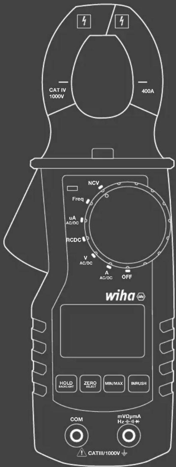
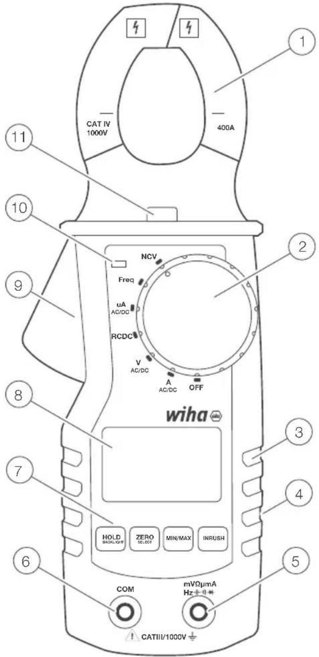
Operation elements and connections
Clamp control and connection elements
① Clamp hook
② Rotary switch
③ Grip area
④ On the rear: battery compartment
⑤ Input jack for all measurements (see Chapter "Measurements" on page 23)
6 Ground/COM jack for voltage, mA current, resistance, continuity, capacitance, diode, frequency measurements
7 Control keys
⑧ LC display
⑨ Clamp trigger
10 NCV detection LED
11 Torch light

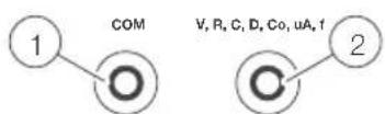
45219
① Common (return) terminal for all measurements.
② Input terminal for voltage, resistance, continuity, capacitance, frequency and uA measurements
Button functions
The clamp meter has 4 pushbuttons responding to short and long presses. Functions of each button are described in table below.
| Short press Long press | |||
| Torch/LPF | A mode | Toggle torch on/off | Toggle LPF on/off |
| V mode | Toggle torch on/off | Toggle LPF on/off | |
| RCDC mode | Toggle torch on/off | - | |
| uA mode | Toggle torch on/off | - | |
| Freq. mode | Toggle torch on/off | - | |
| NCV mode | Toggle torch on/off | - | |
| Min/Max | A mode | AlteringMin/Max/Normal | - |
| V mode | AlteringMin/Max/Normal | - | |
| RCDC mode | AlteringMin/Max/Normal | - | |
| uA mode | AlteringMin/Max/Normal | - | |
| Freq. mode | AlteringMin/Max/Normal | - | |
| NCV mode - - | |||
| Hold/Backlight | A mode | Toggle Hold functionon/off | Toggle backlight on/off |
| V mode | Toggle Hold functionon/off | Toggle backlight on/off | |
| RCDC mode | Toggle Hold functionon/off | Toggle backlight on/off | |
| uA mode | Toggle Hold functionon/off | Toggle backlight on/off | |
| Freq. mode | Toggle Hold functionon/off | Toggle backlight on/off | |
| NCV mode | Toggle Hold functionon/off | Toggle backlight on/off | |
| Zero/Select | A mode Altering AC/DC Zero (only ADC) | ||
| V mode | AlteringAC/DC/DCmV | - | |
| RCDC mode Altering R/C/C/Co - | |||
| uA mode Altering AC/DC - | |||
| Freq. mode - - | |||
| NCV mode - - | |||
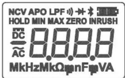
LCD segments

Battery gauge

Alternating current, direct current

Measurement units

Messwert

Zeroing in DC clamp mode

Diode test

Continuity test

LP filter (AC) enabled

Automatic power off enabled

Non-contact voltage active

HOLD is enabled. Display freezes current reading

Maximum, minimum, average reading
Error messages on LCD
OL
The input out of range
Power up options
Automatic power off function (APO) is turned on by default. APO will turn off the clamp meter if passes 15 min. without activity.
Holding HOLD button while rotating switch from OFF to other position switches off Automatic Power Off feature.
User interface description
With the rotary switch user can select the measurement mode. If the clamp meter is in current [A] or voltage [V] mode it will be by default selected AC. Selection DC is manually using Zero/Select button.
Measurements

When connecting the test leads to the circuit or device, connect the common (COM) test lead before connecting the live lead; when removing the test leads, remove the live lead before removing the common test lead.
Voltage measurement

To avoid electrical shock, the valid safety measures and VDE directives strictly have to be met concerning excessive contact voltage when working with voltages exceeding 120 V (60 V) DC or 50 V (25 V) rms AC. The values in brackets are valid for limited areas (such as e.g. medicine, agriculture).
USER'S MANUAL
- Set rotary switch to V position.
- After the clamp meter powers on connect the black test lead to the COM socket and the red test lead to the V/Ω/Cap socket.
- By default, the clamp meter will be in AC measuring mode, to set if for DC press shortly ZERO/Select button.
- Connect test leads to UUT.
- The measured value displayed on the LCD.
Current measurement

Ensure that the measurement circuit is not live when connecting the measurement instrument.

The instruments may only be used in current circuits protected with 400 A up to a nominal voltage of 1000 V. The nominal cross section of connecting line has to be respected and a safe connection has to be ensured.
μA DC
- Set rotary switch to A position.
- After the clamp meter powers on connect the black test lead to the COM socket and red test lead to the V/Ω/Cap./μA socket.
- Connect test leads to UUT.
- The measured value displayed on the LCD.
A AC/DC
- Set rotary switch to A position.
- After the clamp meter powers on connect clamp conductor with unknown current.
- By default, the clamp meter will be in AC measuring mode. Pressing shortly Zero/Select button will switch it to DC mode.
- When measuring DC current use long press on Zero/Select button to null LCD showing.
- The measured value displayed on the LCD.
Resistance measurement

Prior to any resistance measurement it has to be ensured that the resistor to be tested is not live. Failure to comply with this prescription can lead to dangerous corporal user injuries or cause instrument damage. Additionally, external voltages falsify the measurement result.
- Set rotary switch to /Diode/Cap/Continuity position.
- After the clamp meter powers on use short presses of the Zero/Select button to change measurement mode to Resistance.
- Connect the black test lead to the COM socket and red test lead to the V/Ω/Cap socket.
- Connect test leads to UUT.
- The measured value displayed on the LCD.
Continuity test

Prior to any continuity test, it must be ensured, that the element to be tested is not live. Failure to comply with this prescription can lead to dangerous corporal user injuries or cause instrument damage. Additionally, external voltages falsify the measurement result.
The shown value is indicative. The accuracy of continuity mode is lower than in resistance measurement mode. Because of that the resistance measurement shall be used for accurate results.
- Set rotary switch to /Diode/Capacitance/Continuity position.
- After the clamp meter powers on use short presses of the Zero/Select button to change measurement mode to Continuity.
- Connect the black test lead to the COM socket and red test lead to the V/Ω/Capacitance/μA socket.
- Connect test leads to UUT.
• The measured value displayed on the LCD.
Diode test

Prior to any diode test, it must be ensured, that the element to be tested is not live. Failure to comply with this prescription can lead to dangerous corporal user injuries or cause instrument damage. Additionally, external voltages falsify the measurement result.

Resistors and semiconductor paths in parallel to the diode cause falsified measurement results.
- Set rotary switch to /Diode/Capacitance/Continuity position.
- After the clamp meter powers on use short presses of the Zero/Select button to change measurement mode to diode test.
- Connect the black test lead to the COM socket and red test lead to the V/Ω/Capacitance/μA socket.
- Connect test leads to UUT.
- The measured value displayed on the LCD.
Capacitance measurement

Prior to any capacity test, it must be ensured, that the capacity to be tested is not live. Failure to comply with this prescription can lead to dangerous corporal user injuries or cause instrument damage. Additionally, external voltages falsify the measurement result.

Resistors and semiconductor paths in parallel to the capacity cause falsified measurement results.

Ensure that capacitors are discharged prior to testing!
- Set rotary switch to /Diode/Capacitance/Continuity position.
- After the clamp meter powers on Use short presses of the Zero/Select button to change measurement mode to Capacitance.
- Connect the black test lead to the COM socket and red test lead to the V/Ω/Capacitance/μA socket.
- Connect test leads to UUT.
- The measured value displayed on the LCD.
Frequency measurement
- Set rotary switch to Frequency position.
- After the clamp meter powers on connect the black test lead to the COM socket and red test lead to the V/Ω/Capacitance/μA socket.
- Connect test leads to UUT.
- Read the measurement result displayed on the display.
NCV (non-contact voltage) measurement—AC only

Use this function just like indicator and always check presence of voltage using V mode of the clamp!
NCV antenna of the clamp meter is positioned on the right side next to the rotary switch. Rough estimation of the voltage level is presented with a number of dashes on LCD (max 3 dashes/levels).
- Set rotary switch to NCV position.
- After the clamp meter powers on bring the clamp meter antenna area (right side of the clamp next to the rotary switch) near live conductor.
- Number of dashes on LCD will roughly represent level of live voltage, NCV sign will be present to on LCD and the NCV LED will be illuminated.
Additional features
MAX/MIN
Short press on MIN/MAX button switches between minimum, maximum and normal value. This feature is disabled by default. Short press on the button enables displaying MAX value first. Another short press activates displaying MIN value, then MAX and normal value cyclically. These features can be activated in all measurement modes. Appropriate LCD segments will be turned on to signalize MAX or MIN.
HOLD feature
This function enables/disables LCD refreshing. Once the user presses HOLD button (short press) the clamp meter will stop updating LCD. Pressing the button again the clamp meter continues with normal operation. Hold feature is available in all measurement modes. When Hold feature is enabled, HOLD segment will be turned on.
Clamp meter backlight on/off
When powered up, long press on HOLD/Backlight button toggles backlight on/off. When on it is deactivated by timeout (1 minute) or with another long press on HOLD/Backlight button long press. Control is available in all measurement modes.
Clamp meter torch light on/off
When powered up, short press on Torch/LPF button toggles torch light on/off. When on it is deactivated by timeout (1 minute) or with another short press on Torch/LPF button long press. Control is available in all measurement modes.
APO feature
Automatic power off after 15 minutes is active by default, APO LCD segment is turned on to signalize this behavior. In order to disable APO, the device must be turned off. User must keep pressed HOLD/Backlight button and move rotary switch from OFF to any measurement position. When APO is disabled, APO LCD segment will be turned off.
LPF feature (low pass filter)
LPF first order filter provides noise cancelation in ACA and ACV modes. Using of LPF can lower accuracy.
When powered up, long press on Torch/LPF button toggles LPF on/off. LPF is available in current and voltage AC measurement modes. By default, LPF is turned off.
Maintenance
When using the instrument in compliance with the instruction manual, no special maintenance is required. Should operational problems occur during daily use, our consulting service (phone: +49 77-22 959-0) will be at your disposal.
Cleaning
If the instrument is dirty after daily usage, it is advised to clean it by using a humid cloth and a mild household detergent. Prior to cleaning, ensure that instrument is switched off and disconnected from external voltage supply and any other instruments connected (such as UUT, control instruments, etc.).

Prior to cleaning, ensure that instrument is switched off and disconnected from any external voltage supply and any other instrument connected (such as UUT, control instruments, etc.) and not clamped to a live conductor.

Never use acid detergents or dissolvents for cleaning.
Calibration Interval
The instrument has to be periodically calibrated by our service department in order to ensure the specified accuracy of measurement results. We recommend a calibration interval of two years.
Battery replacement

Prior to battery replacement, disconnect the instrument from any connected test leads and ensure that the instrument is not clamped to a live conductor. Only use batteries as described in the technical data section!
- Switch off instrument. Disconnect test leads.
- Loosen the screws on the instrument rear. Lift the battery case cover.
- Remove discharged batteries.
- Insert new batteries.
- Replace the battery case cover and retighten the screws.
Please consider your environment when you dispose of your batteries or accumulators. They belong in a rubbish dump for hazardous waste. In most cases, the batteries can be returned to their point of sale.
Please comply with the respective valid regulation regarding the return, recycling and disposal of used batteries and accumulators.
If an instrument is not used over an extended time period, the accumulators or batteries must be removed. Should the instrument be contaminated by leaking battery cells, the instrument has to be returned for cleaning and inspection to the factory.
Technical data
Display 3 3/4 digit, LC display
Total display 4000 digits
Polarity display automatic
Battery status display empty battery symbol appears (< 2.5 V)
Measurement category CAT IV / 1000 V
Pollution degree 2
Power supply batteries, 2 x 1.5 V, AAA
Dimension approx. 220 mm x 81 mm x 43 mm
Weight approx. 260 g (without batteries)
Ambient conditions
Operating temperature 0...50 °C (0...80% rel. humidity)
Storage temperature -10...60 °C (0...80% rel. humidity) (without batteries)
Height above sea level up to 2000 m
| Feature Range* | 1 | Basic accuracy |
| DC voltage | 400 m | ±(1.5% of meas. val.+ 5 digits) |
| 4 V | ±(1% of meas. val.+ 3 digits) | |
| 40 V | ||
| 400 V | ||
| 1500 V | ±(1,5% of meas. val.+ 3 digits) | |
| AC voltage*2 *3 *5 | 400 m | ±(1.5% of meas. val.+ 5 digits) |
| 4 V | ±(1% of meas. val.+ 5 digits) | |
| 40 V | ||
| 400 V | ||
| 1000 V | ||
| DC Current—Jaws | 40 A | ±(2% of meas. val.+ 5 digits) |
| 400 A | ||
| DC Current—Jacks 400 uA | ±(1.5% of meas. val.+ 5 digits) | |
| AC Current—Jaws*3 *4 | 40 A | ±(2% of meas. val.+ 5 digits) |
| 400 A | ||
| AC Current—Jacks 400 uA | ±(1.8% of meas. val.+ 5 digits) | |
| Resistance | 400 Ohm | ±(1.5% of meas. val.+ 3 digits) |
| 4 kOhm | ||
| 40 kOhm | ||
| 400 kOhm | ||
| 4 MOhm | ||
| 40 MOhm | ||
| Continuity buzzer switching point | 10-50 Ohm | |
| Diode test 0-1 V | ||
| Capacitance | 51.2 nF *6 | ±10% typically |
| 512.0 nF | ±(1.5% of meas. val.+ 5 digits) | |
| 5,120 uF | ||
| 51.2 uF | ±10% typically | |
| 100 uF *7 | ||
| Frequenz | 5.000 Hz | +/- 0.1% + 1D |
| 50.00 Hz | ||
| 500.0 Hz | ||
| 5.000 kHz | ||
| 50.00 kHz | ||
| 500.00 kHz | ||
| 5.000 MHz | ||
| TRMS + | ||
USER'S MANUAL
| Feature Range* | 1 | Basic accuracy |
| NCV + | ||
| LPF + | ||
| Overvoltage cat. CATIV 1000 V | ||
| Backlight + | ||
| Torch light + | ||
| LPF -3dB freq. 1 kHz | ||
Technical data refer to 23 °C ± 5 °C at < 80% rel. humidity
Temperature coefficient 0.15 x specified accuracy per 1°C (<18 °C and >28 °C)
*1 The lowest range is specified from 5% of range to 100% of range.
* Signal BW 40 Hz ... 1 kHz
* If signal is mixed (AC + DC) only pure AC component will be taken into account
*4 Frequency of AC current up to 400 Hz
*5 With increasing frequency (over 400 Hz) accuracy decreases
* Specification is valid for capacitance > 10 nF
^47 Maximum measurement time is 15s
Service and warranty
Should the device no longer work, should you have any questions or require information, contact an authorised customer service point for Wiha power tools:
Customer care
Wiha Werkzeuge GmbH
Tel.: +49 7722 959-0
Obertalstraße 3 - 7
Fax: +49 7722 959-160
78136 Schonach
Email: info.de@wiha.com
GERMANY
Website: www.wiha.com
The warranty is voided in the event of injury or damage to property caused due to non-compliance with these instructions. The manufacturer accepts no liability for consequential damage!
Table des matières
Website: www.wiha.com
MASSIMO/MINIMO....12
NCV (Non-Contact Voltage Measurement) - kun AC

NCV (Non-Contact Voltage Measurement) - kun AC

NCV (Non-Contact Voltage Measurement) - endast AC 124
Ytterligare funktioner 124
MAX/MIN 124
HOLD-funktion....124
NCV (Non-Contact Voltage Measurement) - endast AC

NCV (non-Contact Voltage Measurement) - vain AC.... 12
Lisätoiminnot 12
MAX/MIN 12
HOLD-toiminto....12
Puristin taustavalo PÄÄLLE/POIS 12
Purista taskulamppu ON/OFF 12
APO-toiminto 12
NCV (non-Contact Voltage Measurement) - vain AC

NĚMECKO Web: www.wiha.com
Tools that work for you
Wiha Werkzeuge GmbH
Obertalstraße 3 – 7
78136 Schonach
GERMANY
Tel.: +49 7722 959-0
Fax: +49 7722 959-160
Website: www.wiha.com