45215 - Multimeter Wiha - Free user manual and instructions
Find the device manual for free 45215 Wiha in PDF.

User questions about 45215 Wiha
0 question about this device. Answer the ones you know or ask your own.
Ask a new question about this device
Download the instructions for your Multimeter in PDF format for free! Find your manual 45215 - Wiha and take your electronic device back in hand. On this page are published all the documents necessary for the use of your device. 45215 by Wiha.
USER MANUAL 45215 Wiha
Digitales Multimeter Digital multimeter
Bereich
Minimum/Maximum/Durchschnitt (MIN/MAX/AVG) Messung
BEDIENUNGSANLEITUNG
Website: www.wiha.com
Introduction / Scope of supply 21
Transport and storage 22
Safety references 22
Operation elements and connections 23
Buttons....23
Measurement modes 27
Carrying out measurements 28
Voltage measurement 28
NCV (Non-contact voltage measurement) 28
Frequency measurement 29
Resistance measurement....29
Continuity measurement 29
Diode test 29
Capacitance test.... 30
Temperature measurement 30
Current measurement 30
Maintenance 31
Cleaning 31
Calibration interval 32
Battery replacement.... 32
Fuse replacement 32
Technical Data 33
Service and warranty....36
References marked on instrument or in instruction manual

Warning of a potential danger, follow with instruction manual.

Reference! Please use utmost attention.

Caution! Dangerous voltage. Danger of electrical shock.

Continuous double or reinforced insulation category II IEC 536 / DIN EN 61140.

Complies with EU specifications.

Complies with UK specifications.

Instrument fulfils the standard (2012/19/EU) WEEE. This marking indicates that this product should not be disposed with other household wastes throughout the EU. To prevent possible harm to the environment or human health from uncontrolled waste disposal, recycle it responsibly to promote the sustainable reuse of material resources. To return your used device, please use the return and collection systems or contact the retailer where the product was purchased. They can take this product for environmental safe recycling.
CAT IV/600 V; CAT III/1,000 V
Instrument complies to Measurement Category CAT IV/600 V and CAT III/1,000 V against earth.
Description
CAT II: Measurement category II is applicable to test and measuring circuits connected directly to utilization points (socket outlets and similar points) of the low-voltage MAINS installation.
CAT III: Measurement category III is applicable to test and measuring circuits connected to the distribution part of the building's low-voltage MAINS installation.
CAT IV: Measurement category IV is applicable to test and measuring circuits connected at the source of the building's low-voltage MAINS installation.

The instruction manual contains information and references, necessary for safe operation and maintenance of the instrument. Prior to using the instrument, the user is kindly requested to thoroughly read the instruction manual and comply with it in all sections.

Failure to read the instruction manual or to follow with the warnings and references contained herein can result in serious bodily injury or instrument damage. The respective accident prevention regulations established by the professional associations are to be strictly enforced at all times.
Introduction / Scope of supply
You have purchased a high-quality measurement instrument which will allow you to carryout measurement over a long-time period. The multimeters are universally usable. The multimeters were built after the latest safety regulations.
The multimeters are a valuable help in the handcraft or industrial area as well as for the hobby electronics technician at all standard measurement tasks.
The digital multimeter is characterised by the following features:
• Digital multimeter with extra large display
- 3 34 -digit LC display with 6.000 counts and bargraph
- Safety according to DIN VDE 0411, EN 61010, IEC 61010, CATIII/1,000 V
• Voltage (measures up to 1,000 V), current and resistance measurement
• Non-contact voltage test (NCV)
• V SCAN mode: Automatic AC/DC detection and measurement
- Separate mV AC/DC measurement
• Diode and acoustical continuity test function
• Temperature measurement
• Capacity, frequency and duty cycle measurement
• Automatic range selection
- Buttons with Hold, Relative, Minimum, Maximum and Average functions
• Auto power-OFF function
- Impact and shock proof due the standard protective holster
- Compact size
Lieferumfang
• 1 x Digital multimeter 45215
- 1 x Protective holster
- 2 x Test leads (1x red, 1x black)
• 2 x Batteries 1.5 V, IEC LR03
• 1 x Instruction manual
Transport and storage
Please keep the original packaging for later transport, e.g. for calibration. Any transport damage due to faulty packaging will be excluded from warranty claims. In order to avoid instrument damage, it is advised to remove accumulators when not using the instrument over a certain time period. However, should the instrument be contaminated by leaking battery cells, you are kindly requested to return it to the factory for cleaning and inspection.
Instruments must be stored in dry and closed areas. In the case of an instrument being transported in extreme temperatures, a recovery time of minimum 2 hours is required prior to instrument operation.
Safety references

The respective accident prevention regulations established by the professional associations for electrical systems and equipment must be strictly met at all times.

The respective accident prevention regulations established by the professional associations are to be strictly enforced at all times regarding body protection in the event of danger of burns.

In order to avoid electrical shock, the valid safety and VDE regulations regarding excessive contact voltages must receive utmost attention, when working with voltages exceeding 120 V (60 V) DC or 50 V (25 V) rms AC. The values in brackets are valid for limited ranges (as for example medicine and agriculture).

Measurements in dangerous proximity of electrical systems are only to be carried out in compliance with the instructions of a responsible electronics technician, and never alone.

If the operator's safety is no longer ensured, the instrument is to be put out of service and protected against use. The safety is no longer insured, if the instrument:
• shows obvious damage.
• does not carry out the desired measurements.
• has been stored for too long under unfavourable conditions.
- has been subjected to mechanical stress during transport.

The instrument may only be used within the operating ranges as specified in the technical data section.

Avoid any heating up of the instrument by direct sunlight to ensure perfect functioning and long instrument life.

The opening of the instrument for fuse replacement, for example, may only be carried out by professionals. Prior to opening, the instrument has to be switched off and disconnected from any current circuit.

The instrument may only be used under those conditions and for those purposes for which it was conceived. For this reason, in particular the safety references, the technical data including environmental conditions and the usage in dry environments must be followed. When modifying or changing the instrument, the operational safety is no longer ensured.
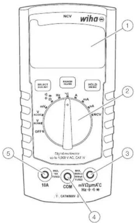
Operation elements and connections
① LC-display with backlight
② Measurement function selection switch
③ Input sockets for measurement ranges
④ Ground connection for all measurement ranges
⑤ Input socket for current measurement range 10 A
Buttons
Each button is shared by two functions (SELECT and BACKLIGHT, RANGE and RELATIVE, HOLD and MIN/MAX/AVG).
Activate short-press function (SELECT, RANGE or HOLD) by pressing the appropriate button and then releasing it after single-beep sound (it will take less than 1 s).
Activate long-press function (BACKLIGHT, RELATIVE or MINIMUM/MAXIMUM/AVERAGE) by pressing the appropriate button and then releasing it after single and then double-beep sound (it will take more than 1 s to hear the double-beep sound).
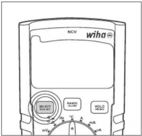
Select
Use SELECT button to cycle through different measurement modes that share the same position on the dial:
• AC/DC voltage measurement (in V and mV modes)
• Resistance, continuity, diode, capacitance
• Temperature scales: °C or °F
• AC/DC current measurement (in 10 A, mA and μA modes)
INSTRUCTION MANUAL
To select desired measurement mode
Apply short press (less than 1 s) on the SELECT button. After one beep sound release the button.
Backlight
To turn backlight on/off
Press BACKLIGHT button and hold it pressed (for more than 1 s) until you hear double-beep sound.

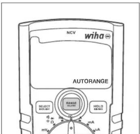
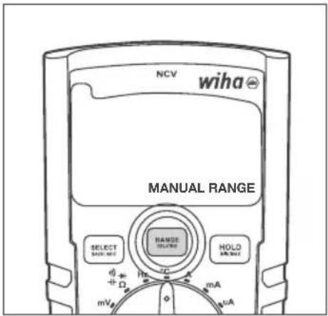
Range
Use RANGE button to toggle between Auto Range and Manual Range modes and cycle through different Manual Ranges as described below:
- When in Auto Range, short press (less than 1 s) on RANGE/RELATIVE button will switch Multimeter to Manual Range.
- When in Manual Range, short press (less than 1 s) on RANGE/RELATIVE button will cycle through different Manual Ranges.
- When in Manual Range, long press (more than 1 s) on RANGE/RELATIVE button will switch Multimeter back to Auto Range.
To switch to Manual Range
When in Auto Range mode, apply short press (less than 1 s) on the RANGE button. After one beep sound release the button.
To switch to the next Manual Range
When in Manual Range mode, apply short press (less than 1 s) on the RANGE button. After one beep sound release the button.
To switch back to Auto Range
When in Manual Range mode, apply short press (less than 1 s) on the RANGE button. After one beep sound release the button.
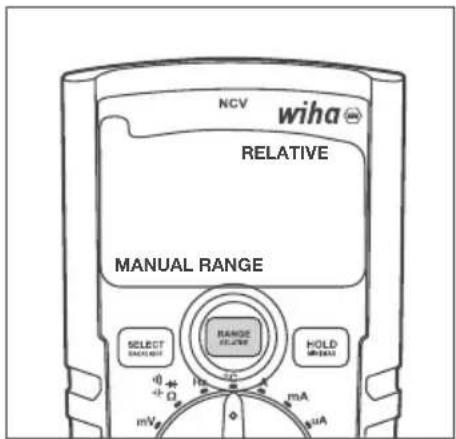
Relative
Use RELATIVE button to activate or deactivate the Relative function. Multimeter MUST be in Auto Range mode before applying Relative function, unless it is in mV, continuity, diode or temperature measurement, which operate in Manual Range mode only.
- When in Auto Range, long press (more than 1 s) on RANGE/RELATIVE button activates Relative function (and at the same time Manual Range mode).
- When in Relative mode, long press (more than 1 s) on RANGE/RELATIVE button will exit Relative function and set multimeter back to Auto Range mode.
To activate Relative function
When in Auto Range mode, press RELATIVE button and hold it pressed (for more than 1 s) until you hear double-beep sound.

Multimeter enters Relative and Manual Range modes at the same time.

When multimeter exits Relative function it also returns to Auto Range mode.
To deactivate Relative function and switch back to Auto Range
Press RANGE button and hold it pressed (for more than 1 s) until you hear double-beep sound.
INSTRUCTION MANUAL
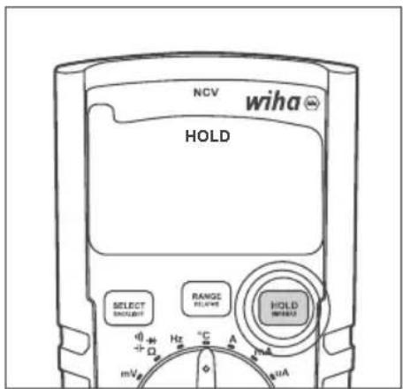
Hold
Use HOLD button to activate/deactivate Hold function.
- Short press (less than 1 s) on HOLD button activates Hold function.
- Next short press (less than 1 s) on HOLD button deactivates Hold function.
To activate/deactivate Hold function
Apply short press (less than 1 s) on the HOLD button. After one beep sound release the button.
When enabled, HOLD will appear on LCD. When disabled, it will not be present on LCD.
Minimum/Maximum/Average (MIN/MAX/AVG) measurement
Use MIN/MAX button to activate/deactivate and cycle through Minimum, Maximum and Average measurement.
- Long press (more than 1 s) on HOLD/MIN/MAX button activates Minimum, Maximum and Average functions. The LCD shows the minimum value that has been measured. Whenever a new minimum value is detected and shown on the LCD, it is also indicated by a short beep.
- Next short press (less than 1 s) on HOLD/MIN/MAX button shows the maximum value that has been measured. Whenever a new maximum value is detected and shown on the LCD, it is also indicated by a short beep.
- Next short press (less than 1 s) on HOLD/MIN/MAX button shows the average value that has been measured. Each next constitutive short press on HOLD/MIN/MAX button cycles through the MIN, MAX and AVG measurements.
- Long press (more than 1 s) on HOLD/MIN/MAX button when any of MIN, MAX or AVG functions are shown on the LCD deactivates Minimum, Maximum and Average functions.
To activate Minimum/Maximum/Average function
Press MIN/MAX button and hold it pressed (for more than 1 s) until you hear double-beep sound.
The first function that is shown on LCD is MIN.
To cycle through the MIN, MAX and AVG functions
Apply short press (less than 1 s) on the MIN/MAX button. After one beep sound release the button.
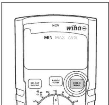
To deactivate Minimum/Maximum/Average function
Press MIN/MAX button and hold it pressed (for more than 1 s) until you hear double-beep sound 1 s) on the MIN/MAX button. After one beep sound release the button.
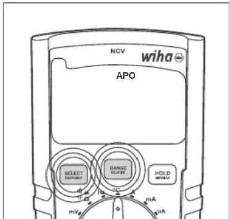
APO (Automatic Power Off)
When on, APO function will power down Multimeter after 15 minutes of inactivity. APO can be turned off and back on at any time by pressing SELECT and RANGE buttons at the same time for longer than 1 s. The LCD will indicate APO function when it is enabled. If it is disabled, APO indication will be missing from the LCD.
Press SELECT and RANGE buttons at the same time and hold them pressed until you hear double-beep sound.
When enabled, APO will appear on LCD. When disabled, APO will disappear from the LCD.
Measurement modes
Set the desired measurement by turning the dial so it points at the appropriate position. Power off the Multimeter by positioning the dial to the OFF position. Dial positions are as follows:
• OFF: Multimeter is turned off.
- V SCAN: Automatic AC/DC detection and measurement: In V SCAN mode multimeter automatically detects whether AC or DC voltage is present across the probes and performs the correct type of voltage measurement. Proper AC/DC recognition is valid for the voltages greater than 0.3 V.
- V AC/DC: Manual selection of the type of voltage measurement. Use SELECT button to toggle between AC and DC measurement modes.
• mV: mV measuring mode.
- Ω ➕ ➕: Resistance, continuity, diode and capacitance measurements. Use SELECT button to cycle through these measurement modes.
• Hz: Frequency measurement.
- °C: Temperature measurement in °C or °F scale. Use SELECT button to toggle between °C and °F measurement scales.
• A: Current measurement in 10 A range.
• mA: Current measurement in mA range.
- A: Current measurement in A range.
- NCV: Non-contact voltage mode measures the strength of the electric field. Point the top of the multimeter, which is labelled with NCV, towards the source of the electric field (power cable, power socket or light switch). Stronger the electric field multimeter detects, more horizontal lines will appear on the LCD and faster beeping will be heard. If multimeter detects no electric field it will indicate "EF" on the LCD.
Carrying out measurements
Commissioning
General Information to carry out measurements:

Measurements in dangerous proximity of electrical systems are only to be carried out in compliance with the instructions of a responsible electronics technician, and never alone.

Test leads and test probes may only be touched at handle surfaces provided. Absolutely avoid the direct contact of the test probes. Prior to switching to a new measurement range or a new type of measurement, remove all connections from UUT (circuit / unit under test).

Measurements have to be carried out by respecting the standards.
Voltage measurement

To avoid electrical shock, the valid safety measures and VDE directives strictly have to be met concerning excessive contact voltage when working with voltages exceeding 120 V (60 V) DC or 50 V (25 V) rms AC. The values in brackets are valid for limited areas (such as e.g. medicine, agriculture).
AC voltage measurement
- Select VAC or VSCAN measurement mode via measurement function selection switch.
- Connect the black test lead to the COM socket and the red test lead to the mV Ω μmA °C Hz + - - - - - - - - - - - - - - - - - - - - - - - - - - - - - - - - - - - - - - - - - - - - - - - - - - - - - - -
- Connect test leads to UUT.
- Read the measurement result displayed on the display.
DC voltage measurement
- Select VDC or VSCAN measurement mode via measurement function selection switch.
- Connect the black test lead to the COM socket and the red test lead to the mV Ω μmA °C Hz + - - - - - - - - - - - - - - - - - - - - - - - - - - - - - - - - - - - - - - - - - - - - - - - - - - - - - - -
- Connect test leads to UUT.
- Read the measurement result displayed on the display.
AC mV voltage measurement
- Select mV measurement mode via measurement function selection switch.
- Multimeter will automatically enter in mV AC mode.
- Connect the black test lead to the COM socket and the red test lead to the mV Ω μmA °C Hz ➕ ➕ ➕ socket.
- Connect test leads to UUT.
- Read the measurement result displayed on the display.
DC mV voltage measurement
- Select mV measurement mode via measurement function selection switch.
- Press "Select" button once to enter mV DC measurement mode.
- Connect the black test lead to the COM socket and the red test lead to the mV Ω μmA °C Hz +→→→ socket.
- Connect test leads to UUT.
- Read the measurement result displayed on the display.
NCV (Non-contact voltage measurement)
- Select NCV measurement mode via measurement function selection switch.
- Point the top of the 45215 multimeter, which is labelled with NCV, towards the source of the electric field (power cable, power socket or light switch).
- Read the measurement result displayed on the display (stronger the electric field multimeter detects, more horizontal lines will appear on the LCD and faster beeping will be heard. If Multimeter detects no electric field it will indicate "EF" on the LCD).
Frequency measurement
- Select Hz measurement mode via measurement function selection switch.
- Connect the black test lead to the COM socket and the red test lead to the mV Ω μmA °C Hz + - + + + socket.
- Connect the test leads to UUT.
- Read the measurement result displayed on the display.
Resistance measurement

Prior to any resistance measurement it has to be ensured that the resistor to be tested is not live. Failure to comply with this prescription can lead to dangerous corporal user injuries or cause instrument damage. Additionally, foreign voltages falsify the measurement result.
- Select - - - measurement mode via measurement function selection switch.
- If necessary, use SELECT button to set the measurement. Press SELECT button to cycle through resistance, continuity, diode and capacitance measurements.
- Connect the black test lead to the COM socket and the red test lead to the mV Ω μmA °C Hz + - - - - - - - - - - - - - - - - - - - - - - - - - - - - - - - - - - - - - - - - - - - - - - - - - - - - - -
- Connect the test leads to UUT.
- Read the measurement result displayed on the display.
Continuity measurement

Prior to any resistance measurement it has to be ensured that the resistor to be tested is not live. Failure to comply with this prescription can lead to dangerous corporal user injuries or cause instrument damage. Additionally, foreign voltages falsify the measurement result.
- Select measurement mode via measurement function selection switch.
- If necessary, use SELECT button to set the measurement. Press SELECT button to cycle through resistance, continuity, diode and capacitance measurements.
- Connect the black test lead to the COM socket and the red test lead to the mV Ω μmA °C Hz + - + + + socket.
- Connect the test leads to UUT.
- Read the measurement result displayed on the display.
Acoustic indication by signal sound if resistance < 30 Ω.
Diode test

Prior to any diode test, it must be ensured, that the diode to be tested is not live. Failure to comply with this prescription can lead to dangerous corporal user injuries or cause instrument damage. Additionally, foreign voltages falsify the measurement result.

Resistors and semiconductor paths in parallel to the diode cause falsified measurement results.
- Select measurement mode via measurement function selection switch.
- If necessary, use SELECT button to set the measurement. Press SELECT button to cycle through resistance, continuity, diode and capacitance measurements.
- Connect the black test lead to the COM socket and the red test lead to the mV Ω μmA °C Hz + - → socket.
- Connect test leads to UUT.
- Read the measurement result displayed on the display.
Capacitance test

Prior to any capacity test, it must be ensured, that the capacity to be tested is not live. Failure to comply with this prescription can lead to dangerous corporal user injuries or cause instrument damage. Additionally, foreign voltages falsify the measurement result.

Resistors and semiconductor paths in parallel to the capacity cause falsified measurement results.
- Select measurement mode via measurement function selection switch.
- If necessary, use SELECT button to set the measurement. Press SELECT button to cycle through resistance, continuity, diode and capacitance measurements.
- Connect the black test lead to the COM socket and the red test lead to the mV Ω μmA °C Hz + - - - - - - - - - - - - - - - - - - - - - - - - - - - - - - - - - - - - - - - - - - - - - - - - - - - - - -
- Connect test leads to UUT.
- Read the measurement result displayed on the display.
Temperature measurement

Prior to any temperature measurement it has to be ensured that the surface to be measure is not live. Failure to comply with this prescription can lead to dangerous corporal user injuries or cause instrument damage.

To avoid burns only touch UUT by means of the thermocouple.
- Select °C measurement mode via measurement function selection switch.
- Connect the minus pole to the COM socket and the plus pole lead to the mV Ω μmA °C Hz - + + + + + socket.
• Temperature probe leads to UUT. - Read the measurement result displayed on the display.
Current measurement

Ensure that the measurement circuit is not live when connecting the measurement instrument.

The instruments may only be used in current circuits protected with 16 A up to a nominal voltage of 1,000V . The nominal cross section of connecting line has to be respected and a safe connection has to be ensured.

After instruments fuse tripping eliminate the cause for the tripping prior to fuse replacement.
Current measurement μA AC
- Select A measurement mode via measurement function selection switch.
- Multimeter will automatically enter A AC mode.
- Connect the black test lead to the COM socket and the red test lead to the mV Ω μmA °C Hz →→ socket.
- Connect test leads to UUT.
- Read the measurement result displayed on the display.
Current measurement μA DC
- Select mA measurement mode via measurement function selection switch.
- Press "Select" button once to enter DC mode.
- Connect the black test lead to the COM socket and the red test lead to the mV Ω μmA °C Hz → → → socket.
- Connect test leads to UUT.
- Read the measurement result displayed on the display.
Current measurement mA AC
- Select mA measurement mode via measurement function selection switch.
-
Multimeter will automatically enter mA AC mode.
-
Connect the black test lead to the COM socket and the red test lead to the mV Ω μmA °C Hz + - - - - - - - - - - - - - - - - - - - - - - - - - - - - - - - - - - - - - - - - - - - - - - - - - - - - -
- Connect test leads to UUT.
- Read the measurement result displayed on the display.
Current measurement mA DC
- Select mA measurement mode via measurement function selection switch.
- Press "Select" button once to enter DC mode.
- Connect the black test lead to the COM socket and the red test lead to the mV Ω μmA °C Hz + - - - - - - - - - - - - - - - - - - - - - - - - - - - - - - - - - - - - - - - - - - - - - - - - - - - - - -
- Connect test leads to UUT.
- Read the measurement result displayed on the display.
Current measurement A AC
- Select A measurement mode via measurement function selection switch.
- Connect the black test lead to the COM socket and the red test lead to the 10 A socket.
- Connect test leads to UUT.
- Read the measurement result displayed on the display.
Current measurement A DC
- Select A measurement mode via measurement function selection switch.
- Press "Select" button once to enter DC mode.
- Connect the black test lead to the COM socket and the red test lead to the 10 A socket.
- Connect test leads to UUT.
- Read the measurement result displayed on the display.
Maintenance
When using the instrument in compliance with the instruction manual, no special maintenance is required. Should operational problems occur during daily use, our consulting service (phone +49 77-22 959-0) will be at your disposal. If functional errors occur after expiration of warranty, our sales service will repair your instrument without delay.
Cleaning
If the instrument is dirty after daily usage, it is advised to clean it by using a humid cloth and a mild household detergent.
Prior to cleaning, ensure that instrument is switched off and disconnected from external voltage supply and any other instruments connected (such as UUT, control instruments, etc.). Never use acid detergents or dissolvants for cleaning. After cleaning, do not use the device until it is completely dry.
INSTRUCTION MANUAL
Calibration interval
The instrument has to be periodically calibrated by our service department in order to ensure the specified accuracy of measurement results. We recommend a calibration interval of two year years.
Battery replacement

Prior to battery replacement, disconnect the instrument from any connected test leads. Only use batteries as described in the technical data section!
- Switch off instrument. Disconnect test leads.
- Remove discharged batteries.
- Insert new batteries 1.5 V IEC LR03.
- Replace the battery cover and retighten the screws.
- Loosen the screws of the battery cover on the instrument rear. Lift the battery cover.
Please consider your environment when you dispose of your one-way batteries or accumulators. They belong in a rubbish dump for hazardous waste. In most cases, the batteries can be returned to their point of sale.
Please, comply with the respective valid regulation regarding the return, recycling and disposal of used batteries and accumulators.
If an instrument is not used over an extended time period, the accumulators or batteries must be removed. Should the instrument be contaminated by leaking battery cells, the instrument has to be returned for cleaning and inspection to the factory.
Fuse replacement

Prior to fuse replacement, ensure that multimeter is disconnected from external voltage supply and the other connected instruments (such as UUT, control instruments, etc.)

Only use fuses as described in the technical data section! Using auxiliary fuses, in particular short-circuiting fuse holders is prohibited and can cause instrument destruction or serious bodily injury of operator.
- Switch off the instrument. Disconnect test leads.
- Loosen the screws on the instrument rear.
- Lift the case cover.
- Remove the defect fuse.
- Insert new fuse.
- Replace the case cover and retighten the screws.
Fuse (A): F 600 mA / 1,000 V Ceramic 6.3 x 32 mm
Fuse (A): F 10 A / 1,000 V Ceramic 6.3 x 32 mm
Technical Data
Display 3 ^3/4 -digit, LC display
Total display 6,000 counts
Polarity display automatically
Battery status display battery symbol appears (< 2,4 V)
Measurement category CAT IV/600 V; CAT III/1,000 V
Pollution degree 2
Power supply batteries, 2 x 1.5 V IEC LR03, AAA
Dimension approx. 150 x 80 x 45 mm incl. holster
Weight approx. 330 g
Ambient conditions
Operation temperature 0...50 °C (0...80 % rel. humidity)
Storage temperature -10...60 °C (0...80 % rel. humidity) (without batteries)
Height above sea level up to 2,000 m
Overload protection
Fuse (A) F 600 mA / 1,000 V Ceramic 6.3 x 32 mm
Fuse (A) F 10 A / 1,000 V Ceramic 6.3 x 32 mm
Technical data refer to 23 °C ± 5 °C at < 80 % rel. humidity
Temperature coefficient 0.15 x specified accuracy per 1 °C (< 18 °C and > 28 °C)
INSTRUCTION MANUAL
| Measuring range | Resolution Accuracy | |
| DC voltage | 600 mV 0.1 mV | |
| 6.000 V 1 mV | ||
| 60.00 V 10 mV | ||
| 600.0 V 100 mV | ||
| 600 V 1 V | ||
| 1000 V 1 V | ||
| AC voltage | 600 mV 0.1 mV | |
| 6.000 V 1 mV | ||
| 60.00 V 10 mV | ||
| 600.0 V 100 mV | ||
| 600 V 1 V | ||
| 1000 V 1 V | ||
| DC current | 600.0 μA 0.1 μA | |
| 6000 μA 1 μA | ||
| 60.00 mA 10 μA | ||
| 600.0 mA 100 μA | ||
| 6.000 A 1 mA | ||
| 10.00 A 10 mA | ||
| AC current | 600.0 μA 0.1 μA | |
| 6000 μA 1 μA | ||
| 60.00 mA 10 μA | ||
| 600.0 mA 100 μA | ||
| 6.000 A 1 mA | ||
| 10.00 A 10 mA | ||
| Resistance | 60.00 Ohm 0.01 | Ohm ±(10 % of m.v. + 5D) |
| 600.0 Ohm 0.1 | Ohm | |
| 6.000 kOhm 1 | Ohm | |
| 60.00 kOhm 10 | Ohm | |
| 600.0 kOhm 100 | Ohm | |
| 6.000 MOhm 1 | kOhm | |
| 60.00 MOhm 10 | kOhm | |
| 200.0 MOhm 100 | kOhm | |
| Continuity buzzer < 30 Ohm | ||
| Diode test yes, up to 2 V | ||
| Measuring range | Resolution Accuracy | ||
| Capacity test | 6.000 nF 0.001 | nF | ±(10 % of m.v. + 25D) |
| 60.00 nF 0.01 nF | ±(2 % of m.v. | + 10D) | |
| 600.0 nF 0.1 nF | ±(1.5 % of m.v. | + 5D) | |
| 6.000 μF 1 nF | ±(1.5 % of m.v. | + 5D) | |
| 60.00 μF 10 nF | ±(1.5 % of m.v. | + 5D) | |
| 600.0 μF 100 nF | ±(2 % of m.v. | + 10D) | |
| 6.000 mF 1 μF | ±(10 % of m.v. + 25D) | ||
| 60.00 mF 10 μF | ±(10 % of m.v. + 25D) | ||
| Frequency | 600.0 Hz 0.1 Hz | ±0.1 % + 1D | |
| 6.000 kHz 1 Hz | |||
| 60.00 kHz 10 Hz | |||
| 600.0 kHz 100 Hz | |||
| 6.000 MHz 1 kHz | |||
| 60.00 MHz 10 kHz | |||
| Temperature measurement | -200...1.350 °C ±(10 % of m.v. | + 1D) | |
| Data HOLD yes | |||
| RELATIVE value measurement | yes | ||
| MIN/MAX measurement | yes | ||
| Auto/Manual RANGE selection | yes | ||
| DMM battery LOW indication | yes | ||
| NCV measurement (Non-contact AC electric field detection) | yes | ||
| True RMS yes | |||
| Backlight yes | |||
| Display | 6.000 counts, bargraph | ||
| IP rating | IP40 | ||
| Battery | AAA 2x 1.5 V; R03 | ||
| Fuse | Ceramic fuses; F 600 mA/1,000 V and F 10 A/1,000 V | ||
| Standards | EN 61010-1, EN 61010-02-033, EN 61010-031, EN 61326 | ||
| Overvoltage category | CAT IV/600 V; CAT III/1,000 V | ||
| Pollution degree | 2 | ||
| Operating temperature 0...50 °C | |||
| Storage temperatur | -10...60 °C | ||
Note: The lowest ranges are specified from 5 % of the range.
Note: AC Voltage and AC Current ranges are specified up to 400 Hz.
As the frequency increases (over 400 Hz), the accuracy deteriorates.
Service and warranty
Should the device no longer work, should you have any questions or require information, contact an authorised customer service point for Wiha power tools:
Customer care
Wiha Werkzeuge GmbH
Tel.: +49 7722 959-0
Obertalstraße 3 – 7
Fax: +49 7722 959-160
78136 Schonach
Email: info.de@wiha.com
GERMANY
Website: www.wiha.com
The warranty is voided in the event of injury or damage to property caused due to non-compliance with these instructions. The manufacturer accepts no liability for consequential damage!
Table des matières
Mesure Minimum/Maximum/Moyenne (MIN/MAX/AVG)
Activer/désactiver APO
Protection de surcharge
Fusible (A) F 600 mA / 1 000 V Céramique 6,3 x 32 mm
Fusible (A) F 10 A / 1 000 V Céramique 6,3 x 32 mm
Tools that work for you
HANDLEIDING
Uitstel
Minimum/Maximum/Gemiddelde (MIN/MAX/AVG) meting
Meetfuncties:
Website: www.wiha.com
Área
Tools that work for you
Misura minima/massima/media (MIN/MAX/MEDIA).
NCV (Non-Contact Voltage Measurement) 11
Baggrundsbelysning
Areal
Relativ værdimåling
Minimum/Maksimum/Gennemsnit (MIN/MAX/AVG) måling
NCV (Non-Contact Voltage Measurement)
NCV (Non-Contact Voltage Measurement) 11
Frekvensmätning 12
Motständsmätning 12
Kontinuitetstest....12
Diodtest 12
Kapacitet 12
Bakgrundsbelysning
Slå på/stänga av
Område
NCV (Non-Contact Voltage Measurement)
NCV (Non-Contact Voltage Measurement) 11
NCV (Non-Contact Voltage Measurement)
Tools that work for you
KÄYTTÖOPAS
Pidä
NÁVOD K POUŽITÍ
Držet
Minimum/Maximum/Átlagos (MIN/MAX/AVG) mérés
Tools that work for you
Wiha Werkzeuge GmbH
Obertalstraße 3 – 7
78136 Schonach
GERMANY
Tel.: +49 7722 959-0
Fax: +49 7722 959-160
Website: www.wiha.com