PPS 40 B3 - Welding machine PARKSIDE - Free user manual and instructions
Find the device manual for free PPS 40 B3 PARKSIDE in PDF.
| Product type | Plasma cutter (welding machine) |
| Brand | Parkside |
| Model | PPS 40 B3 |
| Dimensions (L x W x H) | 341 x 116 x 237 mm |
| Weight | Approx. 5.0 kg |
| Power supply | 230 V~ 50 Hz single-phase |
| Cutting current | 15 – 40 A |
| Operating pressure | 4 – 4.5 bar (preset to 4 bar) |
| Cutting capacity (steel) | 1 – 12 mm |
| Cutting capacity (aluminum) | 1 – 8 mm |
| Cutting capacity (copper) | 1 – 4 mm |
| Cutting capacity (stainless steel) | 1 – 8 mm |
| Cutting capacity (iron) | 1 – 10 mm |
| Insulation class | H |
| Protection rating | IP21S |
| Safety pictograms | Risk of electric shock, radiation, fumes, etc. |
| Included items | Plasma cutter, ground cable, cutting torch, compressed air hose, 3 electrodes, 3 nozzles, instruction manual |
| Maintenance | Regular external cleaning, replacement of worn electrodes and nozzles |
| Warranty | 3 years (commercial warranty) |
| After-sales service | Ecos Office Forbach, service.fr@cmc-creative.de, 0033 (0) 3 87 84 72 34 |
Frequently Asked Questions - PPS 40 B3 PARKSIDE
User questions about PPS 40 B3 PARKSIDE
0 question about this device. Answer the ones you know or ask your own.
Ask a new question about this device
Download the instructions for your Welding machine in PDF format for free! Find your manual PPS 40 B3 - PARKSIDE and take your electronic device back in hand. On this page are published all the documents necessary for the use of your device. PPS 40 B3 by PARKSIDE.
USER MANUAL PPS 40 B3 PARKSIDE
natural_image
Black industrial welding torch kit with attached clamps and wiring (no visible text or symbols)
text_image
PDF ONLINE www.lidl-service.comPLASMA CUTTER PPS 40 B3
PLASMASCHNEIDER PPS 40 B3
DÉCOUPEUR PLASMA PPS 40 B3
GB IE NI CY MT
PLASMA CUTTER
Operation and Safety Notes
Translation of the original instructions
FR BE CH
DÉCOUPEUR PLASMA
PLASMA KOPHΣ METALΛΩN
Before reading, unfold the page containing the illustrations and familiarise yourself with all functions of the device.
DE AT CH
GB / IE/NI/CY/MT Operation and Safety Notes Page 5
Technical specifications Page 8
Safety instructions.... Page 9
General plasma explanations...... Page 15
Before use Page 15
Installation environment....Page 15
Connecting compressed air...... Page 16
Connecting the cutting burner ...... Page 16
Connecting the earthing cable ...... Page 16
Using the device....Page 16
Operation...... Page 16
Troubleshooting...... Page 17
Maintenance and care ...... Page 19
Maintaining the burner....Page 19
Maintenance...... Page 20
Storage Page 20
Information about recycling and disposal...... Page 20
EU Declaration of Conformity ...... Page 21
Warranty and service information Page 22
Warranty conditions ...... Page 22
Warranty period and statutory claims for defects...... Page 22
Extent of warranty.... Page 22
Processing of warranty claims ...... Page 23
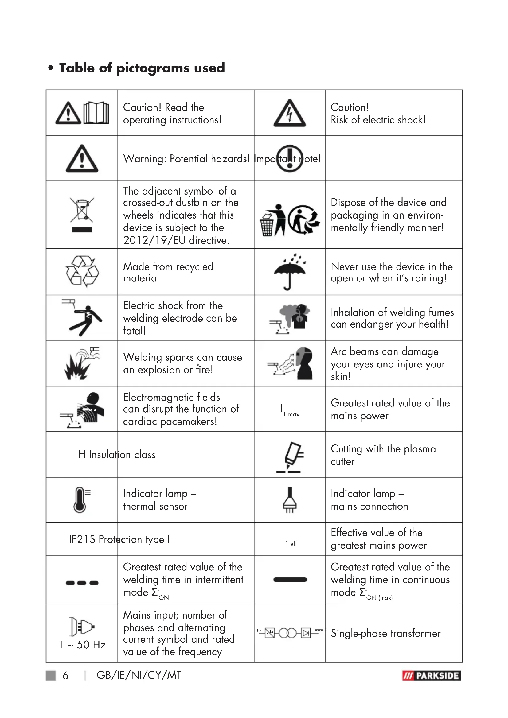
• Table of pictograms used
 | Caution! Read the operating instructions! |  | Caution! Risk of electric shock! |
 | Warning: Potential hazards! | Impo  ote! ote! | |
 | The adjacent symbol of a crossed-out dustbin on the wheels indicates that this device is subject to the 2012/19/EU directive. |  | Dispose of the device and packaging in an environmentally friendly manner! |
 | Made from recycled material |  | Never use the device in the open or when it's raining! |
 | Electric shock from the welding electrode can be fatal! |  | Inhalation of welding fumes can endanger your health! |
 | Welding sparks can cause an explosion or fire! |  | Arc beams can damage your eyes and injure your skin! |
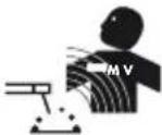 | Electromagnetic fields can disrupt the function of cardiac pacemakers! |  | Greatest rated value of the mains power |
| H Insulation class |  | Cutting with the plasma cutter | |
| [770Z] | Indicator lamp - thermal sensor |  | Indicator lamp - mains connection |
| IP21S Protection type I | 1 eff | Effective value of the greatest mains power | |
 | Greatest rated value of the welding time in intermittent mode Σ _ON^t |  | Greatest rated value of the welding time in continuous mode Σ _ON(max)^t |
  | Mains input; number of phases and alternating current symbol and rated value of the frequency |  | Single-phase transformer |
| U_0 | No-load voltage rated value U_1 | Rated value of the mains voltage |
| U_2 | Standardised operating voltage |
Plasma cutter PPS 40 B3
- Introduction

Congratulations! You have
purchased one of our high-quality products. Please familiarise yourself with the product before using it for the first time. Please also read the safety instructions carefully. This product must be set up or used only by people who have been trained to do so.
Keep out of the reach of children!
NOTE!
The use of the term 'product' or 'device' in the following text refers to the plasma cutter named in these operating instructions.
- Intended use
The device is intended for compressed-air plasma cutting of all electrically conductive metals. Observing the safety instructions and assembly instructions and operating information in the instructions for use is also a component of the intended use. It is imperative to adhere to the applicable accident prevention regulations. The device must not be used:
■ in insufficiently ventilated rooms,
■ in moist or wet environments,
■ in explosive environments,
■ to defrost pipes,
■ in close proximity to people with cardiac pacemakers and
- in close proximity to easily flammable materials.
Use the product only as described and only for the specific applications as stated. Keep these instructions in a safe place. Ensure you hand over all documentation when passing the product on to anyone else. Any use that differs to the intended use as stated above is prohibited and potentially dangerous.
Damage or injury caused by misuse or disregarding the above warning is not covered by the warranty or any liability on the part of the manufacturer. The device is not intended for commercial use. Commercial use will void the guarantee.
RESIDUAL RISK
Even if you operate the device as intended, there will be residual risks.
The following hazards may occur in conjunction with the construction and design of this plasma cutter:
■ Eye injuries due to glare,
■ Touching hot parts of the device or workpiece (burn injury),
In case of improper protection, risk of accident and fire through sparks and slag particles,
■ Harmful emissions from smoke and gases if there is a lack of air or if closed rooms are insufficiently extracted.
Reduce the residual risk by carefully using the device as intended and observing all instruction.
- Package contents
1 plasma cutter
1 earthing cable with clamp
1 cutting cable incl. cutting burner
1 compressed air hose with Quick-Connect
3 electrodes (1 pre-mounted)
1 set of operating instructions
3 burner sleeves (1 pre-mounted)
- Parts description
NOTE!
▶ After unpacking the product, please check that all of the package contents are present and that the device is in perfect condition. Do not use the device if it is defective.
1 Plasma cutter
2 Handle
3 Mains plug
4 Earthing clamp
5 Earthing clamp plug
5a Earthing clamp device plug
5b Earthing clamp connecting plug
6 Plasma burner control plug
7 Plasma burner plug
8 Plasma burner
8a Plasma burner button
8b Nozzle clamping sleeve
8c Burner sleeve
8d Electrode
8e Spacer
8f Interlock switch
9 Overheat protection indicator lamp
10 Plasma burner control socket
11 Earthing clamp connection socket
12 Plasma burner connection socket
12a Cover cap
13 Current controller
14 Mains indicator lamp
15 Quick connector compressed air hose
16 Compressed air hose
17 On/off-switch
I switched on
○ switched off
18 Condensation water tank
19 Manometer
20 Compressed air connection
21 Rotary knob to regulate the pressure
• Technical specifications
Output: 15–40 A
Input: 230 V\~50 Hz
Weight: approx. 5.0 kg
Dimensions: 341 × 116 × 237 mm
Insulation class: H
Cutting
performance: Copper: 1–4 mm
Stainless steel: 1–8 mm
Aluminium: 1–8 mm
Iron: 1–10 mm
Steel: 1–12 mm
Working pressure: 4–4.5 bar (4 bar preset) Changes to technical and visual aspects of the product may be made as part of future developments without notice. Accordingly,
no warranty is offered for the physical dimensions, information and specifications in these operating instructions. The operating instructions cannot therefore be used as the basis for asserting a legal claim.
- Safety instructions
WARNING!
▶ Please read through the operating instructions carefully before use. Familiarise yourself with the device, its proper use and the safety instructions based on these operating instructions. These form part of the product and must be available at all times.
WARNING!
▶ RISK OF SERIOUS INJURY OR DEATH FOR INFANTS AND CHILDREN! Never leave children unsupervised near packaging material. There is a risk of suffocation.
This device may be used by children aged 16 years and older, and by persons with reduced physical, sensory or mental capacities, or a lack of experience and knowledge,
if they are supervised or have been instructed in how to use the device safely and understand the dangers that may arise when using it. Do not allow children to play with the device. Cleaning and day-to-day maintenance must not be performed by children without supervision.
- Repairs and/or maintenance work must only be carried out by qualified electricians. - Only use the cutting cable provided in the scope of delivery. - During operation, the device should not be positioned directly on the wall, covered or jammed between other devices so that sufficient air can be absorbed through the ventilation slats. Make sure that the device is correctly connected to the supply voltage. Avoid any form of tensile stress of the power cable. Disconnect the plug from the socket prior to setting up the device in another location.
If the device is not in operation, always switch it off by pressing the ON/OFF switch. Place the electrode holder on an insulated surface and only remove it from the holder after allowing it to cool down for 15 minutes.
Hot metal and sparks are blown off from the cutting arch. The flying sparks, hot metal as well as hot objects and hot device equipment can cause fires or burns. Check the working environment and make sure the workplace is suitable prior to using the device.
■ Remove all flammable material within 10 m of the plasma cutter. If this is not possible, cover the objects meticulously using suitable covers.
- Do not make cuts in places where flying sparks could come into contact with flammable material.
■ Protect yourself and others from flying sparks and hot metal.
■ Please be careful because sparks and hot materials can easily fall through small gaps and openings while cutting and land on adjacent areas.
- Please be aware that cutting on a ceiling, floor or a partition can cause a fire on the opposite side that is not visible.
■ Connect the power cable using the shortest route with a socket situated close to the workplace to prevent the power cable from being spread across the whole room and located on a surface which could cause an
electric shock, sparks or fire outbreak.
- Do not use the plasma cutter to defrost frozen tubes.
Risk of electric shock:
WARNING!
▶ Electric shock from the cutting electrode can be fatal.
- Do not use the plasma cutter when it is raining or snowing.
■ Wear dry insulating gloves.
- Do not touch the electrodes with bare hands.
- Do not wear wet or damaged gloves.
■ Protect yourself from electric shock with insulation against the workpiece.
■ Do not open the device housing.
■ Additional protection against a shock from the mains power in the event a fault can be provided by using a fault-circuit interrupter, which is operated with a leakage current of no more than 30 mA and covers all mains-powered devices in close proximity. The fault-circuit interrupter must be suitable for all types of current.
■ There must be means of rapid electrical isolation of the cutting power source or the cutting circuit (e.g. emergency
stop device) which are easily accessible.
Danger from smoke emission when plasma cutting:
■ Inhalation of fumes which result from plasma cutting can endanger health.
- Do not keep your head in the fumes.
■ Use the device in open areas.
■ Only use the device in well-ventilated spaces.
Danger from flying sparks when plasma cutting:
■ Cutting sparks can cause an explosion or fire.
- Keep flammable substances away from the cutting location.
- Do not use the plasma cutter near flammable substances.
■ Cutting sparks can cause fires.
- Keep a fire extinguisher close by and an observer should be present to be able to use it immediately.
- Do not carry out plasma cutting on drums or any other closed containers.
Danger from arc beams:
- Arc beams can damage your eyes and injure your skin.
■ Wear a hat and safety goggles
■ Wear hearing protection and high, closed shirt collars.
■ Use a welding safety helmet and make sure that the filter setting is correct.
■ Wear complete body protection.
Danger from electro- magnetic fields:
■ Cutting current generates electromagnetic fields.
■ Do not use if you have a medical implant.
■ Never wrap the cutting cable around your body.
■ Guide cutting cables together.
● Welding mask-specific safety instructions
With the help of a bright light source (e.g. lighter) examine the proper functioning of the welding shield prior to starting with any cutting work.
- Cut spatters can damage the protective screen. Immediately replace damaged or scratched protective screens.
■ Immediately replace damaged or highly contaminated or
splattered components.
■ The device must only be operated by people over the age of 16.
■ Please familiarise yourself with the cutting safety instructions. To that end, you must also observe the safety instructions of your plasma cutter.
■ Always wear a welding helmet while welding and plasma cutting. If it is not used, you could sustain severe lesions to the retina.
■ Always wear protective clothing during welding and plasma cutting operations.
■ Never use the welding shield without the protective screen because this could damage the optical unit. There is a risk of damage to the eyes!
■ Regularly replace the protective screen to ensure good visibility and fatigue-proof work.
● Environment with increased electrical hazard
Environments with increased electrical hazard may be encountered, for example:
In workplaces where the space for movement is restricted,
such that the operator is working in a forced posture (e.g.: kneeling, sitting, lying) and is touching electrically conductive parts;
In workplaces which are restricted completely or in part in terms of electrical conductivity and where there is a high risk through avoidable or accidental touching by the operator;
In wet, humid or hot workplaces where the air humidity or weld significantly reduces the resistance of human skin and the insulating properties or effect of protective equipment.
Even a metal conductor or scaffolding can create an environment with increased electrical hazard.
When using plasma cutters under electrically dangerous conditions, the output voltage of the plasma cutter must be greater than 48 volt when idling (effective value). The plasma cutter may not be used in these cases due to the output voltage.
- Plasma cutting in tight spaces
When welding and plasma
cutting in tight spaces this may pose a hazard through toxic gases (risk of suffocation). In tight spaces the device may only be operated if there are trained individuals in the immediate vicinity who can intervene if necessary. In this case, before starting to use the plasma cutter, an expert must carry out an assessment in order to determine what steps are necessary, in order to guarantee safety at work and which precautionary measures should be taken during the actual cutting procedure.
• Total of no-load voltages
When more than one plasma power source is operated at the same time, their no-load voltages may add up and lead to an increased electrical hazard. The plasma power sources must be clearly marked with their individual control units and connections, in order to be able to identify which device belongs to which circuit.
• Using shoulder straps
The plasma cutter must not be used if the device is being carried e.g. with a shoulder strap. This is intended to prevent:
■ The risk of losing your balance if the lines or hoses which are connected are pulled.
The increased risk of an electric shock as the operator comes into contact with the earth if he/she is using a Class I plasma cutter, the housing of which is earthed through its conductor.
- Protective clothing
At work, the operator must protect his/her whole body by using appropriate clothing and face protection against radiations and burns. The following steps must be observed:
- Wear protective clothing prior to cutting work.
- Wear gloves.
- Open windows to guarantee air supply.
- Wear protective goggles.
■ Gauntlet gloves made of a suitable material (leather) must be worn on both hands. They must be in perfect condition.
A suitable apron must be worn to protect clothing from flying sparks and burns. When specific work, e.g. overhead cutting, is required, a protective suit must be worn and, if necessary, even head protection.
● Protection against rays and burns
Warn of the danger to the eyes by hanging up a sign saying "Caution! Do not look into flames!". The workplaces must be shielded so that the persons in the vicinity are protected. Unauthorised persons must be kept away from cutting work.
The walls in the immediate vicinity of fixed workplaces should neither be bright coloured or shiny. Windows up to head height must be protected to prevent rays being transmitted or reflecting through them, e.g. by using suitable paint.
WARNING NOTICE: Class A devices are intended for use in an industrial environment. Due to the power-related as well as the radiated interference variables, difficulties might arise in ensuring electromagnetic compatibility in other environments.
Even if the device complies with the emission limit values in accordance with the standard, such devices can still cause electromagnetic interference in sensitive systems and devices.
The user is responsible for faults caused by the arc while working, and the user must take suitable protective measures. In doing so, the operator must consider the following:
• EMC Device Classification
According to the standard IEC 60974-10, this is a plasma cutter in electromagnetic compatibility Class A. Class A devices are devices that are suitable for use in all other areas except residential areas and areas that are directly connected to a low-voltage supply mains that (also) supplies residential buildings. Class A devices must adhere to the Class A limit values.
■ Power cables, control, signal and telecommunication lines
■ Computer and other micro-processor controlled devices.
■ Television, radio and other playback devices
■ Electronic and electrical safety equipment
■ Persons with cardiac pacemakers or hearing aids
■ Measurement and calibration devices
■ Noise immunity of other devices in the vicinity
■ The time of day at which the
cutting work is performed.
The following is recommended to reduce possible interference radiation:
■ the plasma cutter must be regularly maintained and kept in good condition
■ Cutting cables should be completely unwound and installed parallel on the floor, if possible
■ Devices and systems at risk interference radiation must be removed from the cutting area if possible, or shielded.
- General plasma explanations
Plasma cutters are operated by pushing pressurised gas, e.g. air, through a small pipe. In the centre of the pipe, there is a negatively charged electrode that is directly above the nozzle. The vortex ring causes the plasma to rotate quickly. If you supply the negative electrode with current and make the tip of the nozzle touch the metal, this connection creates a closed, electrical circuit. A powerful spark occurs between the electrode and the metal. While the gas flows into the pipe, the spark heats up the gas until it has reached the plasma condition. This reaction causes a current from the controlled plasma with a temperature of 16,649 °C or more that moves at speed of 6.096 m/sec and the metal transforms into steam and molten discharge. The plasma itself conducts electrical current.
-The working circuit that allows the arc to occur remains as long as current is supplied to the
electrode and the plasma remains in contact with the metal to be processed.
The cutting nozzle has a range of further channels. These channels generate a constant flow of shielding gas around the cutting area. The pressure of the gas flow controls the radius of the plasma jet.
NOTE!
- This machine is only designed to use compressed air as "gas".
- Before use
• Installation environment
Make sure that the working area is sufficiently ventilated. If the device is used without sufficient cooling, the power-on time reduces and it can result in overheating.
Additional protection can be required for this purpose:
■ The device must be free-standing with a gap of at least 0.5 m all around.
■ Ventilation slots must not be blocked or covered.
The device must not be used as a storage place and tools or other items must not be placed on the device.
It must be operated in a dry and well-ventilated working environment.
- Connecting compressed air
NOTE!
▶This device is designed for operating pressure (output pressure at the compressor) of up to 6.3 bar. Please bear in mind that the pressure can lower while setting the air pressure. Thus, in a hose length measuring 10 m and an internal diameter of 9 mm it drops by approx. 0.6 bar.
The compressed air source must have a filter and regulator.
■ Connect the compressed air hose on the back of the plasma cutter 1 to the compressed air connection 20. To do so, insert the side of the compressed air hose 16 without quick connector into the compressed air connection 20 of the plasma cutter 1 (see Fig. I).
The pressure can be set via the knob on the condensate separator (see Fig. I–L). Select a pressure of 4–4.5 bar.
In order to release the compressed air hose 16, you must press the locking mechanism of the compressed air connection 20 and pull out the compressed air hose 16 at the same time (see Fig. I).
- Connecting the cutting burner
- Pull the cover cab2a off the plasma burner connection socket 12.
- Insert the plasma burner plug into the plasma burner connection socket 12 and tighten the union nut hand-tight (see Fig. A+B).
- Insert the plasma burner control plug into the plasma burner control socket 10 and tighten the union nut hand-tight (see Fig. A+B).
- Connecting the earthing cable
Connect the earthing clamp device plug 5a with the earthing clamp connecting socket 11. Then connect the earthing clamp plug 5 with the earthing clamp connecting plug 5b. Make sure that the connecting shaft is first connected and then turned. The connecting shaft of the earthing clamp device plug 5a must point upwards when plugging in. After plugging in, the connecting shaft must be rotated in a clockwise direction until it reaches the stop, in order to lock it in place (see Fig. A+B). This does not require force!
- Using the device
- Operation
- Set the plasma cutter 1 up in a dry and well ventilated area.
- Position the machine in the vicinity of the workpiece.
- Press the on/off switch 17.
- Clamp the earthing clamp 4 onto the workpiece to be cut and make sure that there is a good electrical contact.
- Set the cutting current on the current controller 13. If the arc beam is inter-
rupted the cutting current must be set higher if necessary. If the electrode burns through frequently, then the cutting current must be set lower.
- Position the plasma burner 8 on the workpiece such that the spacer is in full contact. Push the interlocking switch 8f forwards to lock the plasma burner button 8a in place. Press the plasma burner button 8a. The cutting arc is ignited.
- Start cutting slowly and then increase the speed in order to achieve the desired cutting quality.
- The speed must be regulated so that a good cutting capacity can be achieved.
- When the cutting work is complete push the interlocking switch 8f backwards again.

To cut in manual cutting mode, pull the overlying spacer across the workpiece while maintaining a constant speed. To achieve the perfect cut, it is important for the material thickness to comply with the correct cutting speed. If the cutting speed is too low, the cutting edge will be blunt due to the severe heat input. The optimal cutting speed is achieved once the cutting jet is slightly inclined towards the rear while cutting. If the plasma burner button 8a is released, the plasma jet goes out and the power source switches off. The gas continues to flow for approx. 5 seconds in order to cool the burner. During the gas post-flow time, the plasma cutter 1 must not be
switched off to avoid damaging the plasma burner 8 as a result of overheating.
Explanation of pilot ignition
A pilot arc is ignited by pressing the plasma torch button 8a. This creates a plasma beam on the tip of the torch sleeve 8c. This enables contactless cutting of the workpiece. Mesh and gratings can also be cut in this way.
ATTENTION!
- The device must be left on for approx. 2–3 minutes once the cutting work has been completed. The cooler cools the electronics.
- Troubleshooting
NOTE!
- When the trigger of the burner is pressed, the voltage required for cutting will build up inside the plasma cutter. If the power circuit is then closed, then the voltage which has built up will be discharged through the integrated spark gap. The electrical discharge which results from this within the device does not indicate a malfunction. Check that the device is installed correctly as described in "Using the device".
| Faults Cause of fault Troubleshooting | ||
| Indicator lamp does not light up? | No electrical connection.ON/OFF switch set to off. | Check whether the device is connected to the socket.Set switch to ON. |
| Ventilator does not work? | Power line interrupted.Ventilator power line faulty.Ventilator faulty. | Check whether the device is connected to the socket. |
| Warning lamp switches on? | Overheating protection switched on.Input voltage too high. | Allow device to cool down.Input voltage according to type plate. |
| No output current? | Machine faulty.Overvoltage protection activated. | Machine must be repaired.Allow device to cool down. |
| Outputcurrent does not decrease? | Input voltage too low.Connection cable cross-section too small. | Observe input voltage according to type plate. |
| Air flow cannot be regulated? | Compressed air hose damagedorfaulty.Valve/manometer fails. | New connection of the line. |
| HF-arc is not created? | The burner switch is faulty.Soldering point on the burner switch or plug loosened.Valve/manometer fails. | Replace electrode. |
| Bad ignition? | Burner wear parts damaged or worn. | Change wear parts. |
| Plasma burner8is not ready for operation? | Current switch is switched off.Air transmission is restricted.Workpiece is not connected to the earthing clamp. | Switch the current switch to "on".Another indication of this is a green flame. Check the air supply.Check the connections. |
| Sparks fly upwards,instead of down through the material? | Burner sleeve does not penetrate the material.Burner sleeve is too far away from the material.Material was probably not earthed properly.Lifting speed is too quick. | Increase the current.Reduce the gap between the burner sleeve 8c and material.Check the connection for correct earthing.Reduce the speed. |
| Initial cut but not completely drilled through? | Potential connection problem. | Check all connections. |
| Slag formation on interfaces? | ■ Tool/material creates heat.■ Cutting speed too low or current too high.■ Plasma burner component parts 8b, 8c, 8d are worn. | ■ Allow the material to cool down and then continue cutting.■ Increase the speed and/or reduce the current until the slag has been reduced to a minimum.■ Check and replace worn parts. |
| Arc stops during cutting? | ■ Cutting speed too low.■ Plasma burnes is held too high and too far away from the material.■ Plasma burner component parts 8b, 8c, 8d are worn.■ Workpiece no longer connected to the earthing cable. | ■ Increase the cutting speed until the problem no longer exists.■ Lower the plasma burneto the recommended height.■ Check and replace worn parts.■ Check the connections. |
| Insufficient penetration? | ■ Cutting speed too fast.■ Metal is too thick.■ Plasma burner component parts 8b, 8c, 8d are worn. | ■ Slow down the working speed.■ Several cycles necessary.■ Check and replace worn parts. |
| Consumables wear quickly? | ■ Performance was over-stretched.■ Arc control time exceeded.■ Incorrect plasma burner assembly.■ Insufficient air supply, pressure toolow.■ Faulty air compressor. | ■ Material too thick, increase the angle to avoid material from being blown back into the tip.■ Do not control the arc for more than 5 seconds.■ Check the air filter, increase the air pressure.■ Check the performance of the air compressor and make sure the inlet pressure is at least 100 PSI (6.8 bar). |
- Maintenance and care
- Maintaining the burner
The consumables displayed in Figure F are the electrode 8d and the burner sleeve 8c. They can be replaced once the nozzle clamping sleeve 8b has been unscrewed.
■ The electrode ^ed must be replaced if there is a crater of approximately 1.5 mm depth in the centre.
ATTENTION!
▶To unscrew the electrode, do not apply irregular pressure, gradually increase pressure until the electrode comes out. Then screw in the new electrode into the holder.
The burner sleeve 8c must be replaced if the central bore is damaged or if it has expanded in comparison to the bore of a new nozzle. If the electrode 8d or the burner sleeve 8c are replaced too late, this can result in the parts overheating.
Once replaced, make sure the nozzle clamping sleeve 8b is tightened sufficiently.
ATTENTION!
▶The nozzle clamp sleeve ^8b must only be screwed on to the burner ^8 once it has been fitted with the electrode ^8d and burner sleeve ^8c .
▶If these parts are missing, the device may malfunction and it may create a hazard for the operating personnel.
- Maintenance
NOTE!
▶The plasma cutter must be regularly maintained for perfect function and to comply with the safety requirements. Improper and wrong operation may cause failures and damage to the device. Have repairs only conducted by qualified specialists.
NOTE!
▶ It is not necessary to empty the condensation water container 18. If water collects here then fine droplets will form under the container. The condensation water is then dissipated through evaporation.
Switch off the main power supply and the
main switch of the device prior to carrying out maintenance or repair work on the plasma cutter.
■ Regularly clean the outside of the plasma cutter and its accessories. Use compressed air, cotton waste or a brush to remove dirt and dust.
In case of a defect or a necessary replacement of equipment parts, please contact the appropriate qualified personnel.
- Storage
If you will not be using the device for a while, protect it from dust by storing it in a clean and dry place.
• Information about recycling and disposal
DO NOT DISPOSE OF ELECTRICAL TOOLS IN HOUSEHOLD WASTE! DON'T THROW AWAY
- RECYCLE! According to European Directive 2012/19/EU, used electrical devices must be collected separately for environmentally compatible recycling or recovery. Electrical and electronic devices which have become waste are called old devices. Owners of old devices are obliged to place them in a collection which is separate from unsorted municipal waste. Owners of old devices have old batteries and old rechargeable battery packs, which are not enclosed by the old device, as well as bulbs which must be separated from the device before it is handed in at a collection point. This does not apply if the old devices are handed in to public waste disposal authorities and they are separated from other old devices there for the purposes of preparation for recycling. If you are unsure, please contact an independent specialist.
Owners of old devices from private households can hand these in to collection points for public waste disposal authorities or collection points which have been set up by manufacturers or distributors in line with the ElektroG (German disposal of electrical equipment act). The disposal of defective devices which you have sent in will be carried out free of charge. You can also return the old device to your Lidl branch, free of charge. As the end user, it is your responsibility to delete any personal information on the old devices to be disposed of.

Please return this device, accessories and packaging to your local recycling depot.

This device is marked in accordance with the 2012/19/EU directive on old electronic and electrical devices
(WEEE). The symbol of the “crossed out dustbin” means that you are legally obliged to place these devices in a collection which is separate from unsorted municipal waste. Disposal through household waste is prohibited. Batteries containing harmful substances are labelled with the adjacent symbol, which indicates the prohibition on disposal in household waste. The abbreviations for the relevant heavy metals are: Cd = cadmium, Hg = mercury, Pb = lead.
Take used batteries to a waste management company in your city or community or return them to your dealer. This satisfies your legal obligations while also making an important contribution to protecting the environment.
Please note the marking on the different packaging materials and separate them as necessary. The packaging materials are marked
with abbreviations (a) and digits (b) with the following definitions: 1–7: Plastics, 20–22: Paper and cardboard, 80–98: Composite materials.
• EU Declaration of Conformity
We,
C.M.C. GmbH
Responsible for documentation:
Dr Christian Weyler
Katharina-Loth-Str. 15
66386 St. Ingbert
Germany
hereby take sole responsibility for declaring that the product
Plasma cutter PPS 40 B3
IAN: 365029_2204
Year of manufacture: 03/23
Art. no.: 2527
Model: PPS 40 B3
meets the basic safety requirements as specified in the European Directives
EC Guideline on Electromagnetic Compatibility
2014 / 30 / EU
RoHS Directive
2011 / 65 / EU
EC low-voltage directive
2014 / 35 / EU
and the amendments to these Directives.
The manufacturer will be solely responsible for the creation of the declaration of conformity.
The object of the declaration described above meets the requirements of Directive
2011/65/EU of the European Parliament and of the Council of 8 June 2011 on the restriction of the use of certain hazardous substances in electrical and electronic equipment.
This conformity assessment is based on the following harmonised standards:
EN IEC 60974-6:2016
EN 60974-10:2014/A1:2015
EN IEC 60974-7:2019
pp Dr. Christian Weyler
- Quality Assurance -
- Warranty and service information
Warranty from Creative Marketing & Consulting GmbH
Dear Customer,
The warranty for this equipment is 3 years from the date of purchase. In the event of product defects, you have legal rights against the retailer of this product. Your statutory rights are not affected in any way by our warranty conditions, which are described below.
- Warranty conditions
The warranty period begins on the date of purchase. Please retain the original sales receipt. This document is required as your
proof of purchase.
Should this product show any defect in materials or manufacture within 3 years from the date of purchase, we will repair or replace it – at our discretion – free of charge.
This warranty service requires that you retain proof of purchase (sales receipt) for the defective device for the three year period and that you briefly explain in writing what the fault entails and when it occurred.
If the defect is covered by our warranty, we will repair and return your product or send you a replacement. The original warranty period is not extended when a device is repair or replaced.
- Warranty period and statutory claims for defects
The warranty period is not extended by the guarantee. This also applies to replaced and repaired parts. Any damages or defects detected at the time of purchase must be reported immediately after unpacking.
Any incidental repairs after the warranty period are subject to a fee.
- Extent of warranty
This device has been manufactured according to strict quality guidelines and carefully inspected before delivery.
The warranty applies to material and manufacturing defects only. This warranty does not extend to product parts, which are subject to normal wear and tear and can thus be regarded as consumable parts, or for damages to fragile parts, e.g. switches, rechargeable batteries or parts made from glass.
This warranty is voided if the product
becomes damaged or is improperly used or maintained. For proper use of the product, all of the instructions given in the operating instructions must be followed precisely. If the operating instructions advise you or warn you against certain uses or actions, these must be avoided in all circumstances.
The product is for consumer use only and is not intended for commercial or trade use. The warranty becomes void in the event of misuse and improper use, use of force, and any work on the device that has not been carried out by our authorised service branch.
- Processing of warranty claims
To ensure prompt processing of your claim, please follow the instructions given below.
Please retain proof of purchase and the article number (e.g. IAN) for all inquiries. The product number can be found on the type plate, an engraving, the cover page of your instructions (bottom left), or the sticker on the back or underside of the device. In the event of malfunctions or other defects, please first contact our service department below by phone or email. If your product is found to be defective, you can then send your product with proof of purchase (till receipt) and a statement describing what the fault involves and when it occurred free of charge to the service address given.

Note:
Onwww.lidl-service.com you can download this and several other manuals, product videos and software.
With this QR code you can gain immediate access to the Lidl Service page
(www.lidl-service.com) and you can open your operating instructions by entering the article number (IAN) 365029.
text_image
PDF ONLINE www.lidl-service.comHow to contact us:
GB, IE, NI, CY, MT
Name: C. M. C. GmbH
Website: www.cmc-creative.de
E-mail: service.gb@cmc-creative.de
Phone: 0044 (0) 8081890652
Registered office: Germany
IAN 365029\_2204
Please note that the following address is not a service address. Please first contact the service point given above.
C.M.C. GmbH
Katharina-Loth-Str. 15
66386 St. Ingbert
GERMANY
Ordering spare parts
service.at@cmc-creative.de
service.ch@cmc-creative.de
Telefon: +49 (0) 6894/ 9989750
Dr. Christian Weyler
Katharina-Loth-Str. 15
DE-66386 St. Ingbert
Allemagne
Dr. Christian Weyler
Katharina-Loth-Str. 15
D-66386 St. Ingbert
Duitsland
Dr. Christian Weyler
Katharina-Loth-Str. 15
66386 St. Ingbert
Německo
Dr. Christian Weyler
Katharina-Loth-Str. 15
66386 St. Ingbert
Nemecko
Dr. Christian Weyler
Katharina-Loth-Str., 15
66386 St. Ingbert
Alemania
Dr. Christian Weyler
Katharina-Loth-Str. 15
66386 St. Ingbert
Tyskland
Dr. Christian Weyler
Katharina-Loth-Str. 15
66386 St. Ingbert
Germania
Dr. Christian Weyler
Katharina-Loth-Str. 15
DE-66386 St. Ingbert
Németország
Dr. Christian Weyler
Katharina-Loth-Str. 15
DE-66386 St. Ingbert
Nemčija
Dr. Christian Weyler
Katharina-Loth-Str. 15
DE-66386 St. Ingbert
Njemačka
Greutate: aprox. 5,0 kg
Dimensiuni: 341 x 116 x 237 mm
Dr. Christian Weyler
Katharina-Loth-Str. 15
DE-66386 St. Ingbert
Germania
Dr. Christian Weyler
Katharina-Loth-Str. 15
DE-66386 St. Ingbert
Германия
Dr. Christian Weyler
Katharina-Loth-Str. 15
DE-66386 St. Ingbert
Γερμανία