
PFDS 33 B2 - Welding machine PARKSIDE - Free user manual and instructions
Find the device manual for free PFDS 33 B2 PARKSIDE in PDF.


| Product Type | Flux-Cored Wire Welder (Self-Shielded) |
| Brand | Parkside |
| Model | PFDS 33 B2 |
| Power Supply | 230 V~ / 50 Hz |
| Welding Current Range | 40 – 90 A |
| Duty Cycle | 10% at 90 A, 60% at 40 A |
| Open Circuit Voltage | 32 V |
| Welding Wire Diameter | 0.6 – 0.9 mm (0.9 mm supplied) |
| Max Wire Reel Weight | 450 g |
| Fuse Rating | 16 A |
| Weight | 13.65 kg |
| Protection Type | IP21S |
| Insulation Class | H |
| EMC Classification | Class A (IEC 60974-10) |
| Included Accessories | Welding helmet, chipping hammer with wire brush, carrying strap, 3 welding nozzles (0.6, 0.8, 0.9 mm), flux-cored wire coil (0.9 mm / 450 g) |
| Main Features | Adjustable welding current (MIN/MAX and 1/2 switches), wire feed adjustment wheel, overload protection with auto-reset thermostat |
| Safety Features | Welding helmet with dark lens, protective glass, earth cable, thermal overload protection |
| Warranty | 3 years from date of purchase |
| Intended Use | Self-shielded flux-cored arc welding with appropriate wire; not for pipe thawing or explosive environments |
| Ambient Temperature Rating | 20°C (duty cycle may reduce at higher temperatures) |
Frequently Asked Questions - PFDS 33 B2 PARKSIDE
User questions about PFDS 33 B2 PARKSIDE
0 question about this device. Answer the ones you know or ask your own.
Ask a new question about this device
Download the instructions for your Welding machine in PDF format for free! Find your manual PFDS 33 B2 - PARKSIDE and take your electronic device back in hand. On this page are published all the documents necessary for the use of your device. PFDS 33 B2 by PARKSIDE.
USER MANUAL PFDS 33 B2 PARKSIDE
SALDATRICE ELETTRICA A FILO PFDS 33 B2
IT MT
SALDATRICE ELETTRICA A FILO
Assembly, operating and safety instructions
PT
APARELHO DE SOLDADURA DE FIO DE ENCHIMENTO
Before reading, unfold both pages containing illustrations and familiarise yourself with all functions of the device.
DE AT CH
GB / MT Assembly, operating and safety instructions Page 49
natural_image
Close-up of a gloved hand holding a wire spool over a mechanical component (no visible text or symbols)natural_image
Diagram showing a tool interacting with a spring-like spring on a base, with an arrow indicating motion (no text or symbols)natural_image
Diagram of a precision tool tip welding a metal joint (no text or symbols)natural_image
Simple geometric diagram with two gray rectangles and a label 'S' on the left (no text or symbols within shapes)flowchart
graph TD
    A["W"] --> B["Process 1"]
    A --> C["Process 2"]
natural_image
Close-up of a gloved hand holding a wire spool over a mechanical component (no visible text or symbols)natural_image
Diagram showing a tool pressing a spring on a surface, with an arrow indicating motion direction (no text or symbols)natural_image
Diagram of a precision tool tiping a small object on a surface, with no visible text or symbols.natural_image
Simple geometric diagram with two gray rectangles and a labeled 'S' on the left (no text or symbols within shapes)flowchart
graph TD
    A["W"] --> B["Block 1"]
    A --> C["Block 2"]
e-mail: service.pt@cmc-creative.de
Telephone:707780005
(0,12 Eur / Min.)
Sede: Alemanha
IAN 291492
Intended Use Page 51
Parts Description......Page 51
Technical Data Page 52
Scope of Delivery......Page 52
Safety instructions....Page 52
Safety hazards during arc welding Page 54
Safety notices specific to the welding shield Page 56
Tight and moist spaces ......Page 57
Protective clothing....Page 57
Protecting against rays and burns......Page 57
EMC Device Classification Page 58
Before Use......Page 59
Assembly Page 59
Assembling the welding helmet....Page 59
Inserting the flux-cored wire ......Page 59
Initial Use......Page 62
Switching the unit on and off....Page 62
Adjusting the welding current....Page 62
Adjusting the wire feeder....Page 62
Welding......Page 63
Creating a welding seam....Page 64
Maintenance and Cleaning......Page 65
Environmental instructions and disposal information......Page 65
Information about warranty and service processing......Page 66
Warranty terms Page 66
Extent of warranty....Page 66
Processing of warranty claims......Page 66
Service Page 67
EU Conformity Declaration......Page 67
| List of pictograms used | |||
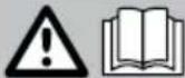 | Caution! Read instructions for use! | WARNING! | Severe or fatal injuries may occur. |
| 1~50Hz | Power input; phase number, as well as |  | Caution! Danger of electric shock! |
| Alternating current symbol and rated value of the frequency |  | Important notice! | |
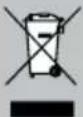 | Do not dispose of electrical equipment in household waste! |  | Dispose of the packaging and unit in an environmentally-friendly manner! |
 | Do not use the unit outdoors and never in rain! | 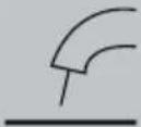 | Self-shielded flux-cored arc welding |
 | Electric shocks from welding electrodes can prove fatal | IP21S | Protection type |
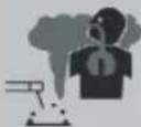 | Inhaling welding smoke can pose a risk to your health. | Suitable for welding with increased electric risk | |
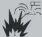 | Welding sparks can cause an explosion or fire. | Single-phase transformer | |
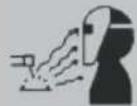 | Arc rays can damage the eyes and injure the skin. | H | Insulation class |
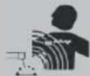 | Electromagnetic fields can interfere with the functionality of pacemakers. | U2 | Standard working voltage |
 | Attention, potential dangers! | I1max | Highest rated value of mains current |
 | Duty cycle | I1eff | Effective value of highest mains current |
| Rated value of welding current | Earth terminal | ||
 | Wire feeder | ||
Flux-Cored Wire Welder PFDS 33 B2
- Introduction
Congratulations! You have chosen a high-quality unit from our company. Familiarise yourself with the product before using it for the first time. In addition, please carefully read the instructions for use and the safety instructions below. Initial operation of this tool must be performed by trained personnel.
KEEP OUT OF THE REACH OF CHILDREN!
Intended Use
This unit is intended for self-shielded flux-cored arc welding using the appropriate wire. Additional gas is not required. The inert gas is contained in a powdered form in the wire, is therefore fed directly into the arc, and this makes the tool wind-resistant while working outdoors. Only suitable wire electrodes may be used for the unit. Intended use also involves observing the safety instructions, assembly instructions and operating instructions in the instruction manual. The applicable accident prevention regulations are to be adhered to as strictly as possible. The unit may not be used:
- in insufficiently ventilated spaces,
- in a damp or wet environment,
- in explosive environments,
- for the purposes of thawing pipes,
- in the vicinity of people with pacemakers and
- in the vicinity of inflammable materials.
Only use the product as described and for the specified purpose. Keep these instructions in a safe place. When passing this product on to others, please also include all the documents. Any use other than the intended is prohibited and potentially dangerous. Damages resulting from noncompliance or misuse are not covered by the warranty and are not included in the manufacturer's liability.
Residual risk
Even if you use the unit correctly, there will always be residual risks. The following hazards can arise due to the design and performance of this flux-cored arc welding unit:
- Eye damage due to being dazzled,
- Touching hot parts of the unit or the work piece (burns),
- In the case of insufficient protection, a risk of accidents and fire exists due to sparks or slag,
- Harmful gas and smoke emissions in the case of a lack of air and / or insufficient extraction in enclosed spaces.
Reduce the residual risk by using the unit carefully and correctly and following all the instructions as stated.
Parts Description
1 Cover for wire feeder unit
2 Carrying strap
3 Mains plug
4 Earth cable with earth terminal
5 Main switch ON / OFF (including mains control lamp)
6 Control lamp for overload protection
7 Burner nozzle
8 MIN / MAX switch for welding current setting
9 1 / 2 Switch for welding current setting
10 Adjustment wheel for wire feeder
11 Burner
12 Burner button
13 Cable assembly with direct connection
14 Welding nozzle (0.6 mm)
15 Welding nozzle (0.8 mm)
16 Handle
17 Welding nozzle (0.9 mm)
18 Flux-cored wire welding coil (wire reel)
∅ 0.9 mm/450 g
19 Chipping hammer with wire brush
20 Welding helmet after assembly, consisting of:
21 Dark welding lens
22 Mask
23 Mounting clip
24 Protective glass locking mechanism
25 Roll holder
26 Wire outlet
27 Adjusting knob
28 Pressing roller unit
29 Feed roller
30 Feed roller holder
31 Cable assembly intake
32 Torch neck
Technical Data
Mains connection: 230 V\~/50 Hz (alternating current)
Welding current I_2 : 40–90A
Duty cycle X: 10 % at 90 A
welding current,
60 % at 40 A
welding current
Open-circuit voltage U_0 :32V
Highest rated value
for the mains current: I
1 max. 14 A
Effective value for highest
rated current: I
2 eff 4.4 A
Welding wire drum max.:
approx. 450 g
Welding wire diameter:
0.9 mm
Fuse: 16 A
Weight: 13.65 kg
- Scope of Delivery
1 Flux-cored arc welding unit PFDS 33 B2
1 Burner nozzle (pre-installed)
3 Welding nozzles (1x 0.9 mm pre-installed; 1x 0.8 mm; 1x 0.6 mm)
1 Chipping hammer with wire brush
1 Flux-cored wire ∅ 0.9 mm/450 g
1 Welding helmet
1 Carrying strap
1 Instructions for use

Safety instructions
Please carefully read the instructions for use and follow the specified notices. Familiarise yourself with the tool, its proper use and the safety notices using these instructions for use. The nameplate contains all the technical data for this welding tool, please learn about the technical facts of this tool.
This device may be used by children aged 16 years and up, as well as by persons with reduced physical, sensory or mental capacities, or lacking experience and / or knowledge, so long as they are supervised or instructed in the safe use of the device and understand the associated risks. Do not allow children to play with the appliance. Cleaning and user maintenance should not be performed by children without supervision.
■ Only have repairs and/or maintenance performed by electrically skilled persons.
■ Only use the welding cables included (PFDS 33 B2 H01N2-D1x10 mm ^4 ).
During use the equipment should not be located directly against a wall, be covered, or be jammed between other equipment to ensure ample air can be taken in through the ventilation louvres. Verify the equipment is correctly connected to the mains voltage. Avoid any tensile load on the mains. Unplug the mains plug from the socket before transferring the equipment to a different location.
■ Always switch the equipment off with the ON / OFF switch when not in use. Set the electrode holder down on an insulated pad and allow to cool for 15 minutes before removing the electrodes from the holder.
■ Pay attention to the condition of the welding cables, the electrode holders and the earth terminals. Worn insulation and conducting parts can produce hazards and reduce the welding quality.
- Arc welding produces sparks, melted metal parts and smoke. Therefore note: Remove any flammable substances and/or materials from the work area and its immediate surroundings.
■ Ensure the work area is ventilated.
- Do not weld atop containers, receptacles or pipes, which do or did contain flammable liquids or gasses.
WARNING! Avoid any direct contact with the welding circuit. The no-load voltage between the electrode holder and earth terminal can be dangerous, there is a risk of electric shock.
- Do not store or use the equipment in a moist or wet environment or in the rain. The Protection Provision IP21S applies in this respect.
■ Protect the eyes with the appropriate safety glass (DIN Grad 9-10) to be installed in the included welding shield. Use gloves and dry protective clothing free from oil and grease to protect the skin from ultraviolet rays and the arc.
WARNING! Do not use the welding power source to thaw pipes.
Remember:
■ The arc ray can damage the eyes and cause burns to the skin.
- Arc welding produces sparks and drops of molten metal, the welded work piece begins to glow and remains very hot for a relatively
long time. Therefore do not touch the work piece with bare hands.
- Arc welding releases noxious fumes. Be careful not to inhale these as best possible.
■ Protect yourself from the dangerous effects of the arc and keep persons not involved in the work at least 2 m away from the arc.
ATTENTION!
■ Depending on mains conditions at the connection point, operating the welding equipment may interfere with the voltage supply for other loads. When in doubt, please contact your power supply company.
- Operating the welding equipment may interfere with the functionality of other devices, e.g. hearing aids, pacemakers, etc.
●Safetyhazards during arc welding
Arc welding produces a variety of safety hazards. It is therefore particularly important for the welder to observe the following rules to avoid putting himself and others in danger and to prevent damage to persons and the equipment
■ Only have work to the mains voltage end, e.g. to cables, plugs, outlets, etc. performed by a electrically skilled person in accordance with national and local regulations.
In the event of an accident, immediately disconnect the welding equipment from the mains voltage.
If electrical contact voltage occurs, immediately switch the equipment off and have it inspected by an electrically skilled person.
■ Always ensure good electrical contacts on the welding current end.
■ Always wear insulating gloves on both hands whilst welding. These will protect from electric shock (no-load voltage of the welding current), from hazardous rays (heat and UV rays) and glowing metal and weld splashes.
■ Wear solid, insulating shoes. The shoes should also insulate when exposed to moisture. Low shoes are not suitable, as glowing metal drops falling could cause burns.
■ Wear suitable protective clothing, no synthetic garments.
- Do not look into the arc with unprotected eyes, only use a welding shield with approved protective glass per DIN. In
addition to light- and heat rays which could result in blinding or burns, the arc also emits UV rays. Without adequate protection, this invisible ultraviolet radiation causes very painful conjunctivitis which is only noticed a few hours later. UV rays further cause burns similar to a sunburn in unprotected areas of the body.
■ Persons near the arc or assistants must also be informed of the risks and outfitted with the necessary protection. If necessary, set up protective panels.
■ Ensure an adequate supply of fresh air whilst welding, particularly in small spaces, as it produces smoke and harmful gasses.
- Do not weld containers in which gasses, fuels, mineral oils, etc. were stored - even if emptied a long time ago - as residue poses an explosion hazard.
■ Special regulations apply in rooms posing fire- and explosion hazards.
■ Welded joints exposed to great strain and needing to meet certain safety requirements must be made by specially trained and certified welders. Examples are pressure vessels, running rails, tow couplings, etc.
⚠️ATTENTION! Always connect the earth terminal as close as possible to the point of weld to provide the shortest possible path for the welding current from the electrode to the earth terminal. Never connect the earth terminal to the housing of the welding equipment!
Never connect the earth terminal to earthed parts far away from the work piece, e.g. a water pipe in another corner of the room. This could otherwise damage the protective bonding system of the room you are welding.
- Do not use the welding equipment in the rain.
- Do not use the welding equipment in a moist environment.
■ Only place the welding equipment in a level location.
The output is rated at an ambient temperature of 20 °C. The welding time may be reduced in higher temperatures.
Danger of electric shock:

Electric shock from a welding electrode can be fatal.
Do not weld in rain or snow. Wear dry insulating gloves. Do not touch the electrode with bare hands. Do not wear wet or damaged gloves.
Protect yourself from electric shock by insulating from the work piece. Do not open the equipment housing.
Danger due to welding smoke:
Inhaling welding smoke can jeopardize your health. Keep your head out of the smoke. Use facilities in open areas. Use ventilation to remove smoke.
Danger due to welding sparks:
Welding sparks can cause an explosion or fire. Keep flammables away from the welding area. Do not weld next to flammables. Welding sparks can cause a fire. Keep a fire extinguisher nearby and an observer ready to use it. Do not weld on top of drums or any closed containers.
Danger due to arc rays:
Arc rays can damage the eyes and injure the skin. Wear a hat and safety goggles. Wear hearing protection and a closed, high shirt collar. Wear welding helmets and proper filter sizes. Wear full personal protection.
Danger due to electromagnetic fields:
Welding current produces electro- magnetic fields. Do not use along with medical implants. Never wrap the welding cables around the body. Consolidate welding cables.
● Safety notices specific to the welding shield
■ Using a hot light source (e.g. lighter) always check the welding shield is working properly before starting to weld.
■ Welding splashes can damage the glass shield. Replace damaged or scratched glass shields immediately.
■ Promptly replace damaged or heavily soiled/splashed components.
■ The equipment may only be operated by persons who have turned 16.
■ Familiarise yourself with the safety instructions for welding. Also refer to the safety instructions of your welding equipment.
■ Always use the welding shield when welding. Failure to use the shield may result in serious injuries to the retina.
■ Always wear protective clothing when welding.
■ Never use the welding shield without protective glass, as the optics can otherwise be damaged.
■ Replace the protective glass early to ensure good visibility and fatigue-proof working.
- Tight and moist spaces
- When working in tight, moist or hot spaces, use insulating pads and intermediate layers in addition to gauntlet gloves made from leather or other insulating materials to insulate the body from earth.
- When using welding equipment in electrically dangerous conditions, e.g. in tight spaces from conductive walls (kettles, pipes, etc.), in wet spaces (soaking of work clothes), the output voltages of the welding equipment may not be higher than 48 Volts (rms value) in open loop. Based on the output voltage this welding equipment may be used in these conditions.
- Protective clothing
- Whilst working the welder must be protected against rays and burns all over the body with the appropriate clothing and face protection. Remember the following steps:
- Put on protective clothing before welding.
- Put on gloves.
- Open windows or vent to ensure air supply.
- Wear safety goggles and a mask.
■ Wear gauntlet gloves made from suitable material (leather) on both hands. These must be in good condition.
■ Wear suitable aprons to protect the clothing from sparks and burns. When required based on the working method, e.g. welding overhead, wear a protective suit and, if necessary, a head guard.
●Protectingagainst rays and burns
Mark the work area with a sign „Danger! Do not look into flames!” to indicate the risk to the eyes. If possible, shield the
work areas to protect persons nearby. Keep unauthorised persons away from the welding area.
■ Walls in the direct vicinity of fixed work areas should be neither light coloured nor glossy.
Protect windows against rays passing through or reflecting at a minimum to head height, e.g. with suitable paint.
• EMC Device Classification
This is a welding unit with Class A electromagnetic compatibility in accordance with the IEC 60974-10 standard. Therefore, it fulfils the applicable requirements for industrial and domestic use. It may be connected to the public low voltage electricity supply in residential areas. Even when the flux-cored arc welding unit complies with standardized emission thresholds, electric arc welding units may cause electromagnetic interference in sensitive systems and devices.
The user is responsible and must undertake the appropriate safety measures for interference which results from arcs during the welding process. In doing so, the user must take the following into account in particular:
- Power, control, signal and telecommunications cables
- Computers and other microprocessor-controlled devices
- Televisions, radios and other play-back devices
- Electronic and electric safety equipment
- People with pacemakers or hearing aids
- Measuring devices and calibration devices
- Interference immunity of other devices in the vicinity
- The time of day during which welding work is being carried out.
To reduce potential interference radiation, it is recommended that you:
- Equip the mains connection with a mains filter or shield it with a metal pipe
- Regularly perform maintenance work on the flux-cored arc welding unit and keep it in good condition
- Weld cables should be as short as possible, fully unwound and run as parallel on the ground as possible
- Potential equalization should be provided
- The work pieces should be properly earthed
- Devices and systems susceptible to interference radiation should be removed from the welding area if possible or shielded.
- Before Use
Remove all parts from the packaging and inspect whether the flux-cored arc welding unit or the individual parts are visibly damaged. If this is the case, do not use the flux-cored arc welding unit. Contact the manufacturer using the service address stated.
Remove all protective film and other transport packaging.
☐ Check that all items included in the scope of delivery are present.
- Assembly
Assembling the welding helmet
☐ Insert the dark welding lens into the mask with the writing to the top 22 (see Fig. A). The marking on the dark welding lens 21 must be visible from the front of the welding helmet.
☐ Push the handle into the suitable notch on the mask from the inside until it clicks in (See Fig. B).
- Inserting the flux-cored wire
WARNING! To prevent the hazard of an electrical shock, injury or damage, pull the mains plug from the socket before maintenance or preparing for work.
Note: Depending on the application, different welding wires may be required. Welding wires with
a diameter from 0.6 - 0.9 mm can be used with this unit.
The feed roller, welding nozzle and wire cross-section must always be compatible.
The unit is suitable for wire reels up to a maximum of 450g.
☐ Unlock and open the cover for the wire feeder unit 1 by lifting the threaded rod up from the slotted hole.
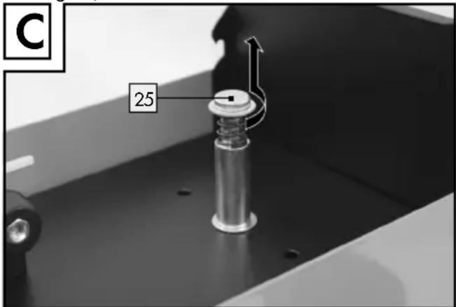
☐ Unlock the roller unit by turning the roller holder 25 clockwise (see Fig. C).
☐ Remove the roller holder from the shaft (see Fig. C).
Note: Please ensure that the wire end does not loosen and that the roll does not automatically roll away. The wire end may only be loosened during assembly.
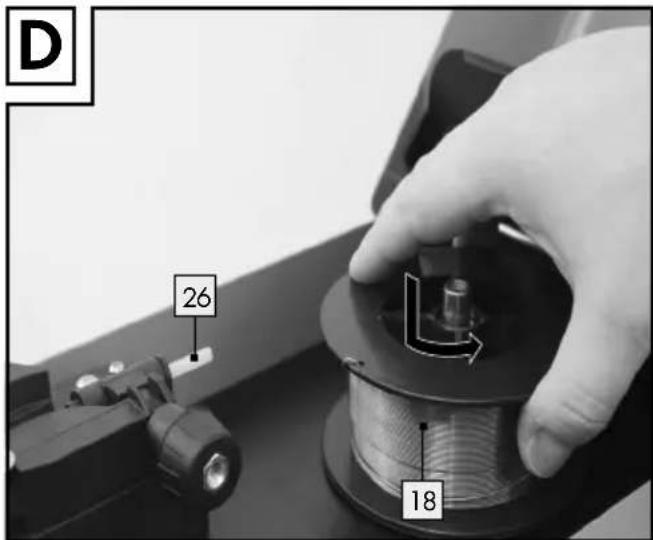
Unwrap the flux-cored wire welding completely so that it can be unrolled freely. However, do not loosen the wire end just yet (see Fig. D).
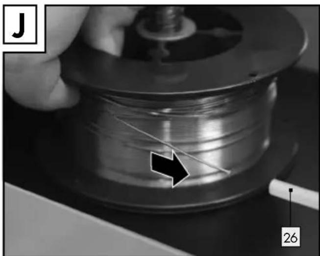
Place the wire reel onto the shaft. Ensure that the roll uncoils on the side with the wire outlet 26 (see Fig. D).
☐ Reattach the roller holder 25 and lock it by pressing on it and turning it counterclockwise (see Fig. D).
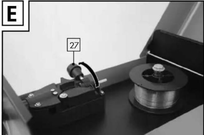
☐ Loosen the adjusting knob and pivot it upwards (see Fig. E).
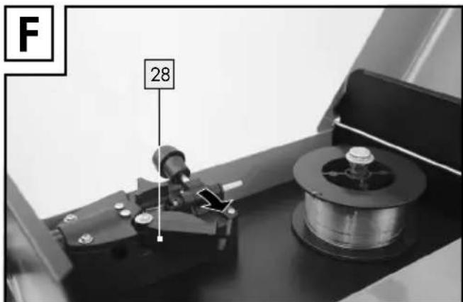
Turn the pressing roller u28 to the side (see Fig. F).
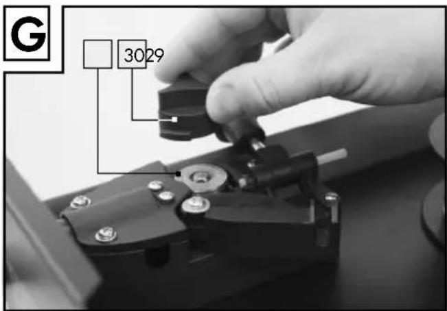
☐ Loosen the feed roller hold 80 by turning it counterclockwise and remove it by pulling it upwards (see Fig. G).
☐ Check the top of the feed roll to see if the appropriate wire thickness is set. If necessary, the feed roller must be turned around or replaced. The welding wire supplied (∅ 0.9 mm) must be
used in the feed roller 29 with the next highest wire thickness diameter of ∅ 0.9 mm.
The wire must be in the upper notch!
☐ Reattach the feed roller holder 30 and screw it tightly.
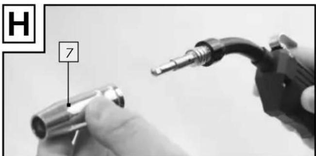
Remove the burner nozzle by rotating it clockwise (see Fig. H).
□ Unscrew the welding nozzle (see Fig. H).
Lead the cable assembly away from the welding unit in as straight a line as possible (place it on the floor).
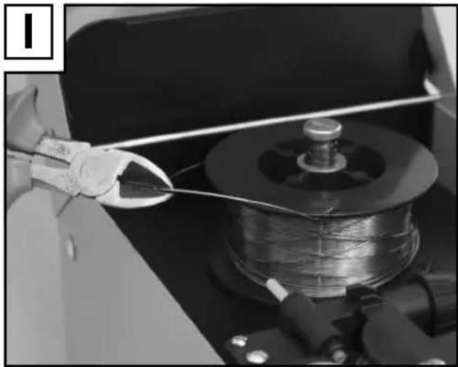
☐ Remove the wire end from the coil edge (see Fig. 1).
☐ Shorten the wire end using a wire cutter or side cutter to remove the damaged/bent wire (see Fig. 1).
Note: The wire must be kept taut the entire time to prevent it from loosening and unrolling!
It is recommended that you always carry out work with another person.
natural_image
Close-up of a wire being held by a pliers, with a spool and mechanical components visible (no text or symbols)☐ Push the flux-cored wire through the wire outlet 26 (see Fig. J).
natural_image
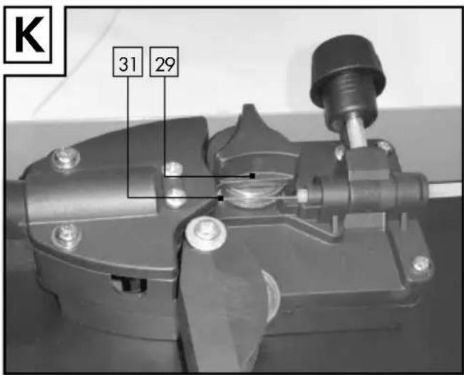
Close-up of a wire spool being sewn by a hand, with a black arrow pointing to the fiber (no text or symbols visible)☐ Lead the wire along the feed roll ^29 and then push it into the cable assembly intake ^31 (see Fig. K).
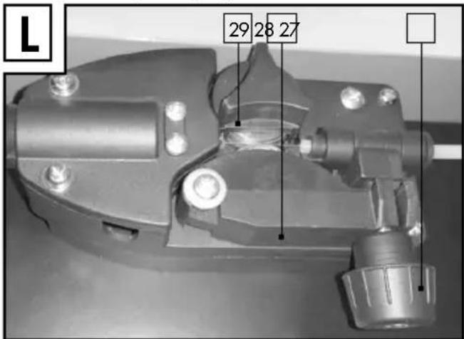
Pivot the pressing roller up in the direction of the feed roller 29 (see Fig. L). Mount the adjusting knob (see Fig. L). Adjust the counter-pressure using the adjusting knob in such a way that the welding wire sits tightly between the pressing roller and the feed roller 29 in the upper duct without being squashed (see Fig. L).
☐ Switch the welding unit on using the main switch 5.
Press the burner button2. Now the wire feeder system will push the welding wire through the cable assembly 13 and the burner 11.
As soon as the wire protrudes 1 - 2 cm from the torch neck 32 you can release the burner button 12 once more (see Fig. M).
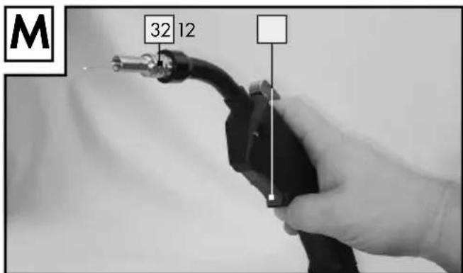
☐ Switch the welding unit off again.
□ Screw the welding nozzle back on.
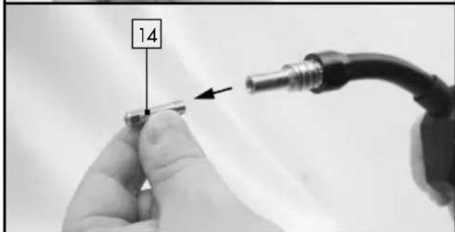
Ensure that the welding nozzle 14 matches the diameter of the welding wire being used (see Fig. N).
For the welding wire supplied ( 0.9 mm) the welding nozzle 14 with the next highest diameter of 1.0 mm must be used.
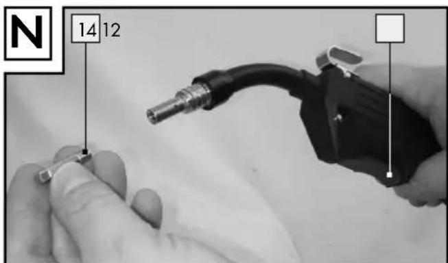
☐ Push the burner nozzle 7 back onto the torch neck 32 by rotating it clockwise (see Fig. O).
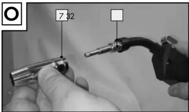
WARNING! To prevent the hazard of an electrical shock, injury or damage, pull the mains plug from the socket before maintenance or preparing for work.
- Initial Use
- Switching the unit on and off
☐ Switch the welding unit on and off using the main switch 5. If you do not use the welding unit for an extended period, pull the plug out of the mains socket. It is only then that the unit will not be supplied with any current.
- Adjusting the welding current
You can adjust the desired welding current using the switches 8 9 on the front of the welding unit. If, for example, the MIN switch 8 and switch 1 9 are up, the welding current amounts to 40 A and the duty cycle is 60 %.
If, for example, the MAX switch 8 and switch 2 9 are down, the welding current amounts to 90 A and the duty cycle is 10 %.
The required welding current depends on the welding wire diameter, the material thickness and the desired weld penetration depth.
- Adjusting the wire feeder
To achieve a consistent weld, the adjustment wheel for the wire feeder 10 can be used to finely adjust the wire feeder. It is recommended that you start with a setting in the centre position and reduce or increase the speed if necessary.
The required welding current depends on the welding wire diameter used, the material thickness, the desired weld penetration depth and the gaps to be bridged on the work pieces to be welded.
Overload protection
The welding unit is protected against thermal overload with an automatic protective device (thermostat with an autorecloser). The overload protection interrupts the process when the circuit has been overloaded and the yellow control lamp 6 illuminates.
☐ If the protective device has been activated, allow the unit to cool down (approx. 15 minutes). As soon as the yellow control lamp for overload
protection 6 turns off, the unit is ready to use once more.
Welding helmet
WARNING! HEALTH HAZARD! If you
do not use the welding helmet, harmful UV rays and heat emitting from the arc can damage your eyesight.
■ Always use the welding helmet when you weld.
Welding
WARNING! RISK OF BURNS! Hot,
welded work pieces are very hot, meaning that you can burn yourselves on them.
■ Always use a pliers to move hot, welded work pieces.
After you have connected the welding unit to the electricity supply, proceed as follows:
☐ Connect the earth cable with the earth terminal 4 to the work piece to be welded.
Ensure that good electrical contact exists.
☐ The workpiece should be free of rust and paint on the area to be welded.
☐ Select the desired welding current and the wire feeder depending on welding wire diameter, material thickness and desired weld penetration depth.
☐ Switch on the unit.
Hold the welding helm ^20 in front of your face and lead the burner nozzle ^7 along the area of the work piece to be welded.
☐ Press the burner button 12 to generate an arc. When the arc burns, the unit feeds wire into the weld pool.
☐ If the welding spot is big enough, the burner 11 is slowly led along the desired edge.
The gap between the burner nozzle and work piece should be as small as possible (in any case, no more than 10 mm).
☐ If necessary, oscillate it gently to enlarge the weld pool somewhat. For those who are less experienced, it can be difficult to form a decent
arc i.e. the correct setting for the welding current and wire feeder speed.
☐ You can figure out the best welding current and wire feeder speed settings by practicing on a test piece. A well-adjusted arc has a soft, steady humming sound.
The weld penetration depth should be as deep as possible, however, the weld pool should not fall through the work piece.
In the case of rough or harsh rattling, decrease the wire feeder speed or switch to a higher power setting (increase welding current).
If the wire feeder speed is too high and / or the welding current is too low, the welding wire may not melt properly and may dip into the welding seam and into the work piece.
A quiet, dull sound with a flickering arc indicates too low a wire feed.
☐ Increase the wire feeder speed or switch to a lower welding current.
The wire melts even before it has reached the welding seam with a welding current that is too high. The result is that drops from on the welding wire, as well as spraying and an inconsistent arc.
The slag may only be removed from the seam when it has cooled down.
To continue the welding process on an inter- rupted seam:
☐ Firstly, remove the slag from the point of attachment.
Ignite the arc in the weld groove, lead it to the connection point, properly melt the material there and then continue along the welding seam.
⚠️CAUTION! Ensure that the burner is always put down on an insulated surface after welding.
□ Always switch the welding unit after finishing welding work and during breaks, and always pull the mains plug out of the socket.
- Creating a welding seam
Spot-welded seam or forehand welding
The burner is pushed forwards.
Result: The penetration depth is lower, seam width is larger, weld bead is flatter and fault tolerance is greater.
Pull-welded seam or backhand welding
The burner is pulled away from the welding seam.
Result: The penetration depth is higher, seam width is smaller, weld bead is higher and the fault tolerance is lower.
Welded joints
There are two basic joint types in welding technology: butt welding and angle welding (outside edge, inside edge and overlapping).
Butt welded joints
For butt welded joints up to 2mm thick, the welding edges are brought together completely.
For larger thicknesses, see the table below:
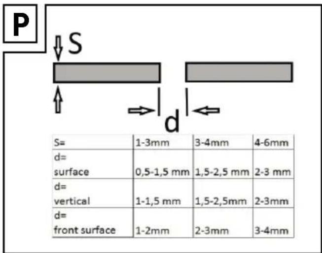
Flat butt welded joints
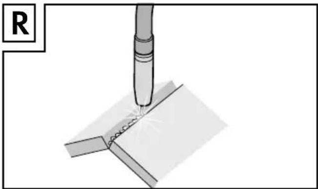
Welding processes should be carried out without interruption and with a sufficient penetration depth. Therefore, good preparation is essential.
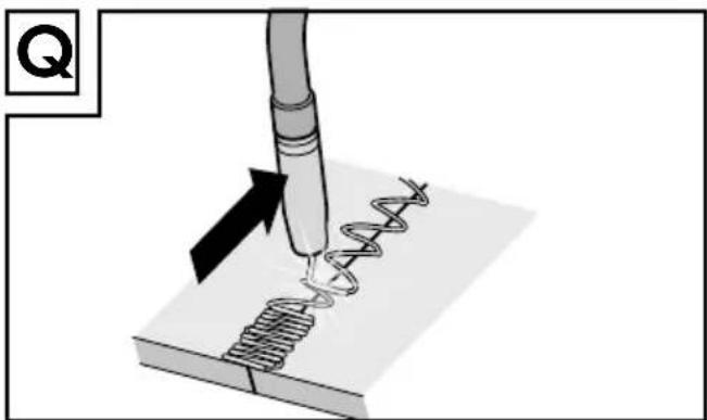
Factors which effect the quality of the welding results include: the welding current, the distance between the welding edges, the burner tilt and the respective welding wire diameter.
The steeper the burner is held in relation to the work piece, the higher the penetration depth and vice versa.
natural_image
Diagram of a precision tool applying material to a helical spring, with no visible text or symbolsTo forestall or reduce deformations which could arise during material hardening it is a good idea where possible to fix the work pieces using a piece of equipment which counteracts the contraction or deformation of the material.
It is recommended that you avoid hardening the welded structure to prevent fractures in the welded seam. These difficulties can be reduced if you are able to rotate the work piece in such a way that the welding process can be carried out in two opposite runs.
natural_image
Diagram of a precision welding process with a tool and weld joint (no text or symbols)Welded joints on outside edges
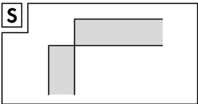
Preparation for this is very simple.
natural_image
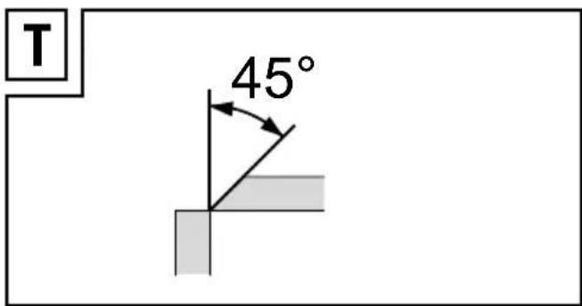
Simple geometric diagram with two gray rectangles and a label 'S' on the left (no text or symbols within shapes)However, this is not practical for stronger materials. In this situation, it is better to prepare a joint as
depicted in the figure opposite, in which the edge of a plate is angled.
Welded joints on inside edges
Preparation for this welded joint is very simple and can be carried out on materials up to 5mm thick. The measurement "d" must be reduced to a minimum and should in any case be less than 2mm.
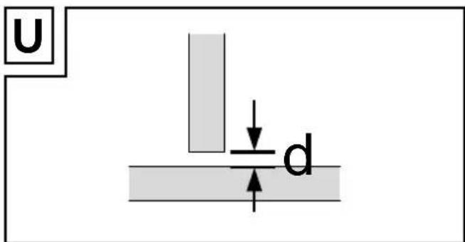
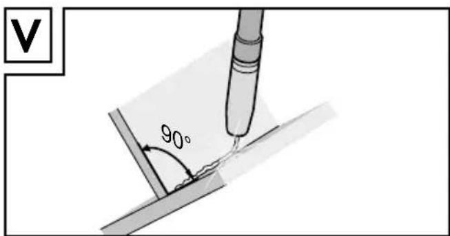
However, this is not practical for stronger materials. In this situation it is better to prepare a joint as depicted in Figure V, in which the edge of a plate is angled.
Overlapping welded joints
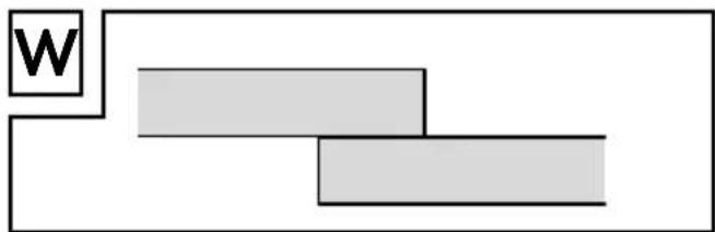
The most common preparation for this is to use straight welding edges. The welding process can be carried out with a normal angle weld seam. Both work pieces must be brought together as closely as possible.
flowchart
graph TD
    A["W"] --> B["Block 1"]
    A --> C["Block 2"]
● Maintenance and Cleaning
Note: The welding tool requires regular maintenance and reconditioning to work properly and to comply with safety requirements. Improper and incorrect operation may result in malfunctions and damage the tool.
☐ Switch off the main power supply and the main switch on the device before maintaining or repairing the welding tool.
☐ Regularly clean the inside and outside of the welding tool. Remove dirt and dust inside the device with air, steel wool, or a brush.
☐ Current regulators, earthing equipment, internal cables, the blowpipe coupler and adjusting screw should be maintained regularly. Tighten loose screws and replace rusty screws.
☐ Regularly check the leakage resistance of the welding tool. Use suitable measuring instruments for this purpose.
In the event of a defect or if components need to be replaced, please contact the corresponding professional.
●Environmentalinstructions and disposal information
Don't waste, recycle!
Device, accessories and packaging should be recycled in an environmentally friendly manner.
Do not dispose of the inverter welder equipment with your household waste, or throw into fire or water. If possible, non-operational equipment should be recycled. Contact your local retailer for information.
● Information about warranty and service processing
Creative Marketing Consulting GmbH warranty
Dear customer, the warranty for this device is 3 years from the date of purchase. In the event of product defects, you have legal rights against the retailer of this product. Your statutory rights are not limited in any way by our warranty detailed below.
- Warranty terms
The warranty period begins on the date of purchase. Please retain the original receipt safely. This document is required as your proof of purchase.
Should this device show any fault in materials or manufacture within three years from date of purchase, it will be repaired or replaced - at our choice - by us free of charge. This warranty is conditional on the defective device and the receipt of purchase (store receipt) being presented within the three year warranty period, and that there is a brief written description of the nature of the defect and of the date it arose.
If the defect is covered by our warranty, we will return the repaired equipment or replacement thereof. A repair or exchange of the equipment does not extend a new warranty period.
• Extent of warranty
The appliance has been manufactured to strict quality guidelines and meticulously examined before delivery.
The warranty applies to faults in material or manufacture. This warranty does not apply to product parts subject to normal wear and tear and which can therefore be considered as wear items, or to damage to fragile parts, e.g. switches, storage batteries or glass parts.
This warranty becomes void if the device has been damaged or improperly used or maintained. All instructions provided in the operating instructions must be followed strictly to constitute proper use of the product. Purposes and practices which the operating instructions warn of or advise against must be avoided without fail.
This product is intended for private, non-commercial use only. Any incorrect or improper use of the device, use of force and changes not performed by our authorized service branch will void the warranty.
- Processing of warranty claims
Please follow the instructions below to ensure your claim is processed quickly:
When inquiring about your product please have your receipt and product number (e.g. IAN 12345) ready as your proof of purchase.
The product number can be found on the type plate, an engraving, the cover page of your instructions (bottom left) or the decal at the back or bottom.
In the event of malfunctions or other defects please first contact the service department below by phone or e-mail.
A product recorded as defective, along with the proof of purchase (sales receipt) and a description of the defect and when it occurred, can then be returned free of charge to you to the service address provided.

Notice:
Download this and many other manuals, product videos and software from www.lidl-service.com.
- Service
How to contact us:
GB, MT
Name: C. M. C. GmbH
Website:www.cmc-creative.de
E-mail:service.gb@cmc-creative.de
service.ie@cmc-creative.de
Registeredoffice:Germany
IAN 291492
Please note that the following address is not a service address.
Please first contact the service point named above.
Address:
C. M. C. GmbH
Katharina-Loth-Str. 15
DE-66386 St. Ingbert
GERMANY
• EU Conformity Declaration CE
We,
C. M. C. GmbH
Responsible for documentation: Andre Scheer
Katharina-Loth-Str. 15
DE-66386 St. Ingbert
GERMANY
declare in our sole responsibility that the product
Flux-Cored Wire Welder PFDS 33 B2
Serial number: 2056
Year of manufacture: 2017 / 17
IAN: 291492
Model: PFDS 33 B2
meets the basic safety requirements of European Directives
EC Low Voltage Directive
2014/35/EU
EC Directive for Electromagnetic
Compatibility
2014/30/EU
RoHS Directive
2011/65/EU
and its amendments.
The conformity assessment is based on the following harmonised standards:
EN 60974-1:2012
EN 60974-10:2014
AfPS GS 2014:01 PAK
- Quality Control Manager -
natural_image
Close-up of a gloved hand holding a wire spool over a mechanical component (no visible text or symbols)natural_image
Illustration of a soldering iron being inserted into a solder pad, with no text or symbols present.natural_image
Mechanical assembly diagram showing a tool inserted into a component (no text or symbols visible)natural_image
Simple geometric shape composed of two gray rectangles forming an L-shape, with a small letter 'S' in the top-left corner (no text or symbols within the shapes)flowchart
graph TD
    A["W"] --> B["Block 1"]
    A --> C["Block 2"]
service.at@cmc-creative.de
service.ch@cmc-creative.de
Telefon: +49 (0) 6894 9989751
- SALDATRICE ELETTRICA A FILO PFDS 33 B2
- SALDATRICE ELETTRICA A FILO
- APARELHO DE SOLDADURA DE FIO DE ENCHIMENTO
- IAN 291492
- Safety instructions....Page 52
- Before Use......Page 59
- Assembly Page 59
- Initial Use......Page 62
- Maintenance and Cleaning......Page 65
- Environmental instructions and disposal information......Page 65
- Information about warranty and service processing......Page 66
- Warranty terms Page 66
- Service Page 67
- EU Conformity Declaration......Page 67
- Flux-Cored Wire Welder PFDS 33 B2
- - Introduction
- KEEP OUT OF THE REACH OF CHILDREN!
- Intended Use
- Residual risk
- Parts Description
- Technical Data
- - Scope of Delivery
- Safety instructions
- Remember:
- ATTENTION!
- ●Safetyhazards during arc welding
- Danger of electric shock:
- Danger due to welding smoke:
- Danger due to welding sparks:
- Danger due to arc rays:
- Danger due to electromagnetic fields:
- - Tight and moist spaces
- - Protective clothing
- ●Protectingagainst rays and burns
- • EMC Device Classification
- - Before Use
- - Assembly
- Assembling the welding helmet
- - Inserting the flux-cored wire
- - Initial Use
- - Switching the unit on and off
- - Adjusting the welding current
- - Adjusting the wire feeder
- Overload protection
- Welding helmet
- WARNING! HEALTH HAZARD! If you
- Welding
- WARNING! RISK OF BURNS! Hot,
- After you have connected the welding unit to the electricity supply, proceed as follows:
- - Creating a welding seam
- Spot-welded seam or forehand welding
- Pull-welded seam or backhand welding
- Welded joints
- Butt welded joints
- Flat butt welded joints
- Welded joints on outside edges
- Welded joints on inside edges
- Overlapping welded joints
- ● Maintenance and Cleaning
- ●Environmentalinstructions and disposal information
- ● Information about warranty and service processing
- Creative Marketing Consulting GmbH warranty
- - Warranty terms
- • Extent of warranty
- - Processing of warranty claims
- Notice:
- - Service
- How to contact us:
- GB, MT
- Address:
- M. C. GmbH
- • EU Conformity Declaration CE
- EC Low Voltage Directive
- EC Directive for Electromagnetic
- Compatibility
- RoHS Directive
- EN 60974-1:2012
- EN 60974-10:2014
- AfPS GS 2014:01 PAK
Brand : PARKSIDE
Model : PFDS 33 B2
Category : Welding machine