
RP250YDM - Paint spray HiKOKI - Free user manual and instructions
Find the device manual for free RP250YDM HiKOKI in PDF.

| Product type | Water and dust vacuum |
| Brand | HiKOKI |
| Model | RP250YDM |
| Power supply | 220-240 V, 50/60 Hz, 1200 W (nominal), 1400 W (max) |
| Dimensions (L x W x H) | 45 x 39 x 53 cm |
| Weight | 11.0 kg |
| Tank capacity | 30 L (plastic) |
| Air flow (at hose) | 151 m³/h |
| Suction pressure (at hose) | 235 hPa |
| Filter surface area | 8400 cm² |
| Sound level | 69.5 dB (A) |
| Dust category | M (dangerous dusts ≥ 0.1 mg/m³) |
| Main functions | Suction of solids and liquids, automatic filter cleaning (RA mode), power tool socket with automatic start, fill level indicator |
| Operating modes | 0 (off), I (on without vibration), A (automatic mode), RA (automatic mode + filter cleaning) |
| Filter cleaning | By electromagnetic vibration, manual (position R) or automatic (position RA) |
| Tank emptying | With non-woven filter bag or PE disposal bag (for categories M and H) |
| Recommended maintenance | Clean water level sensors regularly, replace dirty filters, use original accessories |
| Safety | Do not vacuum flammable or explosive substances, do not use in explosive atmosphere, disconnect before maintenance, use original parts |
| Spare parts available | Non-woven filter bags FBV35, filter cartridges FK 4300 (cellulose), FKP 4300 (polyester), FKP 4300 HEPA (H14), PE disposal bags |
| Warranty | In accordance with statutory/national regulations, does not cover normal wear or misuse |
Frequently Asked Questions - RP250YDM HiKOKI
User questions about RP250YDM HiKOKI
0 question about this device. Answer the ones you know or ask your own.
Ask a new question about this device
Download the instructions for your Paint spray in PDF format for free! Find your manual RP250YDM - HiKOKI and take your electronic device back in hand. On this page are published all the documents necessary for the use of your device. RP250YDM by HiKOKI.
USER MANUAL RP250YDM HiKOKI
natural_image
Black industrial vacuum cleaner with control panel and wheels (no visible text or symbols)RP250YDM

de Bedienungsanleitung (original)
en Handling instructions
fr Mode d'emploi
es Instrucciones de manejo
pt Instruções de uso
it Istruzioni per l'uso
nl Gebruiksaanwijzing
da Brugsanvisning
sv Bruksanvisning
no Bruksanvisning
fi Käyttöohjeet
el Οδηγίες χειρισμού
tr Kullanım talimatları
pl Instrukcja obsługi
hu Kezelési utasítás
cs Návod k obsluze
sk Pokyny na manipuláciu
ro Instructiuni de utilizare
s| Navodila za rokovanje
hr Upute za rukovanje
bg Инструкция за експлоатация
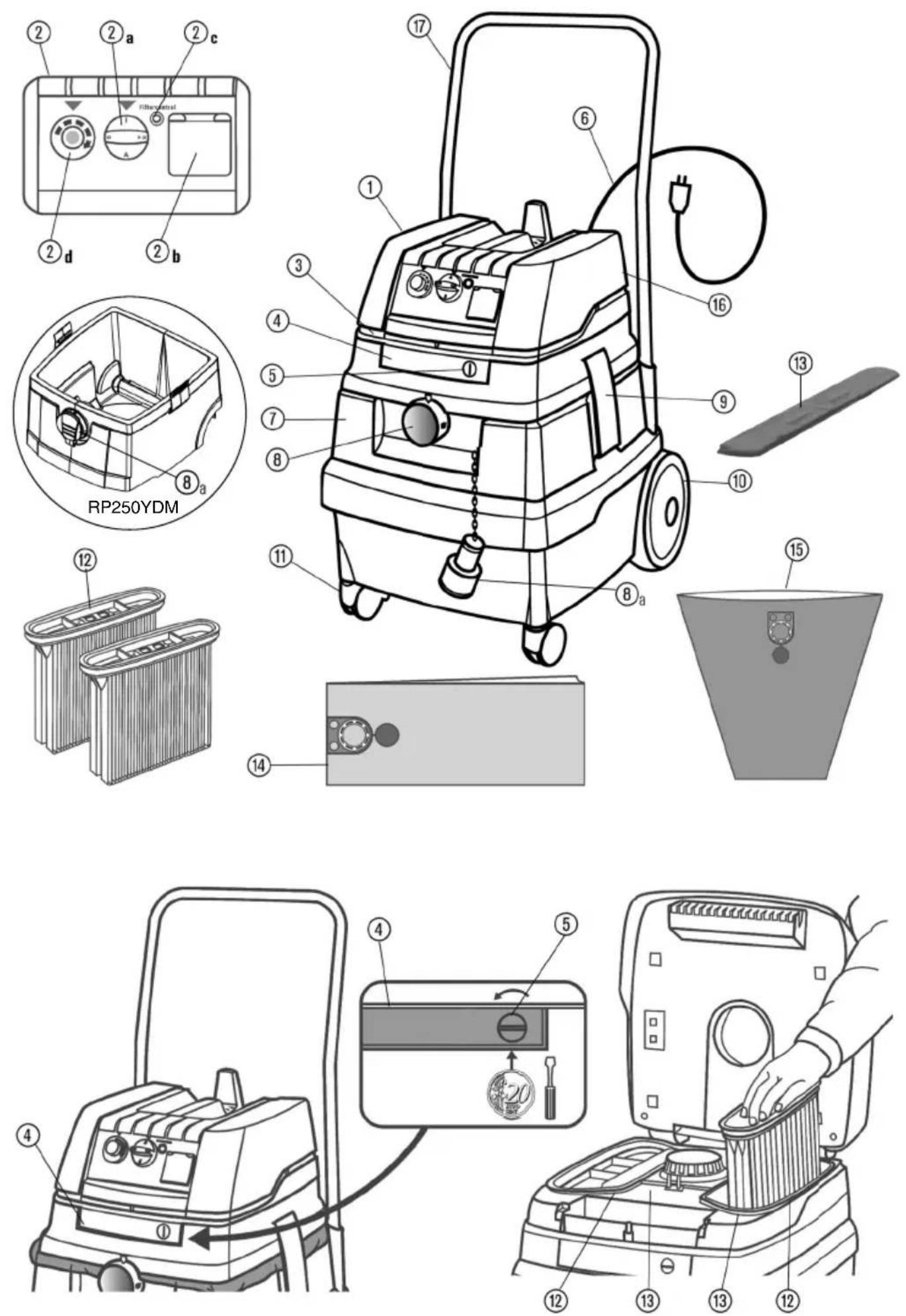
| de Beschreibung | |||
| 1 Oberteil 3 Kühllufteintritt | 8a Verschlussstopfen 4 Vlies-Filterbeutel * | ||
| 2 Funktionsplatte 4 Riegel 9 Rastverschlüsse 5 Kunststoff -Entleerbeutel | |||
| 2a Drehschalter 5 Verschluss 10 Räder 6 Einhängung für Drahtkorb | |||
| 2b Steckdose für Elektrowerkzeug 6 Anschlussleitung 7 Lenkrollen 7 Fahrbügel * | |||
| 2c Volumenstromanzeige (Füllanzeige) | 7 Behälter 12 Filterkassetten | ||
| 2d Einstellung Saugschlauch-Durchmesser | 8 Saugöff nung 13 Motorschutzfi Iter * je nach Modell | ||
| en Description | |||
| 1 Top section 3 Cooling air inlet | 10a Sealing plug | 11 Fleece fi Iter bag * | |
| 2 Functional plate | 4 Latch | 9 Snap-in locks | 10 Plastic emptying bag |
| 2a Rotary switch | 5 Lock | 10 Wheels | 11 Suspension for wire basket |
| 2b Power socket for electric tools | 6 Connecting line | 11 Steering castors | 12 Driving handle * |
| 2c Volume flow display (Fill level indicator) | 7 Container | 12 Filter cassettes | |
| 2d Adjustment of the vacuum hose diameter | 8 Suction opening | 13 Motor protection fi Iter | * depending on model |
| fr Description | |||
| 1 Partie supérieure | 3 Entrée air de refroidissement | 14a Bouchon de fermeture | 15 Sac fi Itre non tissé * |
| 2 Plaque de fonctionnement | 4 Verrou | 9 Fermeture à crans | 16 Sac de vidange en plastique |
| 2a Interrupteur rotatif | 5 Fermeture | 10 Roues | 17 Suspension pour le panier en fil métallique |
| 2b Prise de courant pur outil électrique | 6 Conduite de raccordement | 11 Roues-guides | 18 Etrier de conduite * |
| 2c Affichage du débit volumétrique (Indicateur de niveau de remplissage) | 7 Cuve | 12 Cassettes fi Itre | |
| 2d Réglage du diamètre du fl exible d'aspiration | 8 Oiverture d'aspiration | 13 Filtre de protection du moteur | * selon la variante d'équipement |
| es Descripción | |||
| 1 Parte superior | 3 Entrada de aire frio | 14a Tapón de cierre | 15 Bolsa de fi Itro de fi eltro * |
| 2 Disco de funciones | 4 Enclavamiento | 9 Cierre a presión | 16 Bolsa desechable de plastico |
| 2a Conmutador giratorio | 5 Cierre | 10 Ruedas | 17 Gancho para cesta de alambre |
| 2b Toma de corriente para herramientas eléctricas | 6 Cable de alimentatción | 11 Redecillas de dirección | 12 Barra de transporte * |
| 2c Indicator de fi ujo (Indicator de recipiente lieno) | 7 Recipiente 12 Estuche de fi Itro | ||
| 2d Ajuste del diámetro de la manguera de aspiración | 8 Abertura de spiración | 13 Filtro de protección del motor | * dependiendo del modelo |
| pt Descrição | |||
| 1 Parte superior | 3 Entrada do ar de arrefecimento | 14a Bujão de fecho 15 Saco de fi Itro de vlies * | |
| 2 Placa de funções | 4 Trinco | 16 Encravamentos | 17 Saco de esvaziamento de material plástico |
| 2a Interruptor rotativo | 5 Fecho | 18 Rodas | 19 Gancho para o cesto |
| 2b Tomada para as ferramentas eléctricas | 6 Condutor de alimemação | 10 Rodas dirigíveis | 20 Estribo de condução * |
| 2c Sinalizador da vazão (Indicador do enchimento) | 7 Recipiente 12 Cartuchos de fi Itração | ||
| 2d Ajuste do diâmetro da mangueira de aspiração | 8 Bocal de aspiração | 13 Filtro de proteção do motor | * conforme o modelo |
| it Descrizione | |||
| 1 Parte superiore 3 Entrata aria di raff reddamento | 14a Tappo | 15 Sacchetto fi Itrante in vello * | |
| 2 Pannello di funzionamento | 4 Blocco | 16 Chiusure ad incastro | 17 Saccheni di scarico in plastica |
| 2a Manopola | 5 Chiusura | 18 Ruote | 19 Anacco per cesto metallico |
| 2b Presa per utensili elenrici | 6 Linea di collegamemo | 10 Rulli di guida | 20 Maniglione * |
| 2c Indicazione del fl usso del volu-me (Indicatore serbatoio) | 7 Serbatoio | 12 Cartuccia fi Itro | |
| 2d Impostazione diametro tubo fl essibile di aspirazione | 8 Bocca di aspirazione | 13 Filtro di protezione motore | * in base al modello |
| nl Beschrijving | |||
| 1 Bovendeel 3 Koelluchtinvoeropening | 8a Sluitdop 19 Vlies-fi Iterzak * | ||
| 2 Bedieningspaneel 4 | Vergrendeling | 9 Ketelklemmen 10 Kunststof opvangzak | |
| 2a Draaischakelaar | 5 Slot | 10 Wielen 11 Onhanging voor opergmand | |
| 2b Stopcontact voor elektrisch gereedschap | 6 Netsnoer 12 Zwenkwielen 13 | Duwbeugel * | |
| 2c Volumestroomaanduiding (Niveau-indicatie) | 7 Zwenkweltje | 12 Filtercassetten | |
| 2d Instelling zuigslangdiameter | 8 Zu igopening 13 Motorveiligheidsfi Iter * Al naar model | ||
| da Beskrivelse | |||
| 1 Overdel 3 Køleuftindgang | 9a Tillukningsprop 14 Vlies-fi Iterpose * | ||
| 2 Funktionsplade 4 | Spærre | 9 Snaplas 15 Kunststofpose til at tømme | |
| 2a Drejekontakt | 5 Lukkemekanisme | 10 Hjul 16 Holder til trådkurv | |
| 2b Stikkontakt til El-værktøj | 6 Tiislutningskabel | 11 Styreruller | 12 Kørebøjle * |
| 2c Strømvisning (volumen) (Fyldningsindikator) | 7 Beholder | 13 Filterkassetter | |
| 2d Indstilling af sugeslanges diameter | 8 Sugeåbning | 14 Motorvaernsfi Iter | * alt efter model |
| sv Beskrivning | |||
| 1 Ovandel 3 Kylluftsintag | 15a Förslutningsplugg | 16 Fiberduk fi Iterpåse * | |
| 2 Funktionsplatta 4 | Regel | 17 Ihakningslås | 18 Tömningspase av plast |
| 2a Vridbrytare | 5 Lås | 19 Hjul 20 Upphängning för tillbehörskorg | |
| 2b Uttag för elverktyg | 6 Anslutningskabel | 21 Svängbarahjul | 22 Körhandtag * |
| 2c Volymströmindikering (Fyllnads-indikering) | 7 Behållare | 23 Filterpatroner | |
| 2d Inställning sugeslangens diameter | 8 Sugöppning | 24 Motorskyddsfi Iter | * beroende på modell |
| no Beskrivelse | |||
| 1 Overdel 3 Kjøleluftinngang | 25a Låsepropper | 26 Fleece-fi Iterpose * | |
| 2 Funksjonsplate | 4 Sperre | 27 Låslukking | 28 Tømmepose i kunststoff |
| 2a Dreiebryter | 5 Lås | 29 Hjul 30 Innhengning for trådkurv | |
| 2b Stikkontakt for elektroverktøy | 6 Forbindelsesledn | 30 Styreruller | 31 Kjørebøyyle * |
| 2c Volumstrømangivelse (Fyl-lingsindikator) | 7 Beholder | 32 Filterkassetter | |
| 2d Innstilling sugeslangediameter | 8 Sugeåpning | 33 Motorvernefi Iter | * alt etter modell |
| fi Kuvaus | |||
| 1 Yläosa | 3 Jäähdytysilman tuloaukko | 34a Sulkutulppa | 35 Kuitukangaspölypussi * |
| 2 Toimintopaneeli | 4 Lukitsin | 36 Sulkimet | 37 Muovinen tyjhennyspussi |
| 2a Kiertokytkin | 5 Kiinnitin | 38 Pyörät | 39 Lankakorin ripustin |
| 2b Pistorasia sähkötyökalulle | 6 Verkkojohto | 31 Ohjausrullat | 32 Ohjaustanko * |
| 2c Tilavuusvirtanäyttö (Täyttötason osoitin) | 7 Säiliö | 33 Suodatinkasetit | |
| 2d Letkun läpimitan säädin | 8 Imauukko | 34 Moonorinsuojasuodatin | * rippuen mallista |
| el Περιγραφή | |||
| 1 Επάνω τμήμα | 3 Εισοδος αέρα ψύζης | 35 a Πώμα | 36 Φλις σακούλα σκόνης * |
| 2 Πλάκ λειτουργίας | 4 Μηχανισμός ασφάλισης | 37 Κλείστρα ασφάλισης | 38 Πλαστική σακούλα εκκένωσης |
| 2a Περιστρεφόμενος διακόττης | 5 Ασφάλεια | 39 Τροχοί 40 Στήριγμα συρμάτινου καλαθιού | |
| 2b Μπρίζα για ηλεκτρικές συσκευές | 6 Καλώδιο σύνδεσης | 40 Τροχοί κατεύθυνσης | 41 Λαβή οδήγησης σχήματος U * |
| 2c Ένδείξη όγκου ρεύματος (Ενδείξη πληρότητας) | 7 Κάδος | 42 Κασέτες με φίλτρο | |
| 2d Púθμιση της διαμέτρου του εύκαμπτου σωλήνα αναρρόφησης | 8 Οπή αναρρόφησης | 43 Προστατευτικό φίλτρο κινητήρα | * ανάλογα το μοντέλο |
| tr Açıklama | |||
| 1 Üst kısım 3 Soğuk hava girişi için döner düğme | 8a Kapak tikama buşonu 12 īpek elyaf fi litre torbası * | ||
| 2 Fonksiyon levhası 4 | Kilit sürgüsü | 9 Durma kilitleri 15 Sentetik madde boşaltma torbası | |
| 2a Çevirmeli şalter | 5 Kilit | 10 Tekerler 16 Tel sepet için askı | |
| 2b Elektrikli takım için priz 6 Bağlantı hattı 10 Kilavuz makarası 17 | Tutma demiri * | ||
| 2c Hacim akım göstergesi (Dolum göstergesi) | 7 Depo | 12 Filtre kaseti | |
| 2d Emiş hortumu çap ayarı | 8 Havalandırma deligi 13 Motoru koruma fi ltresi * modele göre | ||
| pl Opis | |||
| 1 Część górna 3 Wlot powietrza zimnego | 8a Korek 14 Worek fi ltrujący z włókniny * | ||
| 2 Panel sterowania 4 | Zasuwa | 9 Zatrzaski 15 Worek do opróżniania ze sztucznego tworzywa kosza | |
| 2a Przełącznik obrotowy | 5 Zamek | 10 Koła 16 Zawieszenie drucianego | |
| 2b Gniazdko wtykowe dlanarz ędzia elektr. | 6 Kabel zasilający | 11 Rolki kierowane | 12 Uchwyt do przenoszenia * |
| 2c Wskaźnik strumienia objętości (Wskaźnik wypełnienia) | 7 Pojemnik | 12 Kasetki fi ltrujące | |
| 2d Ustawienie średnicy węża ssącego | 8 Otwór ssący | 13 Filtr silnika | * Zależnie od modelu |
| hu Leírás | |||
| 1 Felsőrész | 3 Hütőlevegő-belépés | 14a Záró dugó | 15 Fátyolszűrő zacskó * |
| 2 Funkciólemez | 4 Retesz | 16 Becsappanó zárszerkezetek | 17 Műanyag úritőzsák |
| 2a Forgókapcsoló | 5 Zár | 18 Kerekek | 19 Drótkosár beakasztó szerkezete |
| 2b Dugaszoló aljzat villamos szerszámokhoz | 6 Csałlakozó vezeték | 10 Kormánygörgők | 11 Mozgó kengyel * |
| 2c Térfogatáram-kijelző (Töltés kijelző) | 7 Tartály | 12 Szűrőkazetták | |
| 2d Szívócső átmérő beállítás | 8 Szívónyilás | 13 Motorvédő szűrő | * modelltől függően |
| cs Popis | |||
| 1 Horní část | 3 Vstup chladícího vzduchu | 14a Zátka | 15 Rounový fi ltrační sáček * |
| 2 Funkční deska | 4 Západka | 16 Západkové uzávěry | 17 Plastový vyprazdňovací sáček |
| 2a Otočný spínač | 5 Uzávěr | 18 Kolečka | 19 Zavěšení pro drátěný koš |
| 2b Zásuvka pro elektrické nářadí | 6 Pripojovací vedení | 10 Pojezdová kolečka | 11 Madlo * |
| 2c Indikátor objemového proudu (Indikace stavu naplnění) | 7 Zásobník | 12 Filtrační kazety | |
| 2d Nastavení průměru sací hadice | 8 Sací otvor | 13 Ochranný fi ltr motoru * podle modelu | |
| sk Popis | |||
| 1 Horná časť | 3 Vstup chladíaceho vzduchu | 14a Zátka | 15 Tkaninové fi ltračné vrecko * |
| 2 Funkčná doska | 4 Kolieska | 16 Západkové uzávery | 17 Plastové vyprázdňovacie vrecko |
| 2a Otočný spínač | 5 Uzáver | 18 Kolieska 19 Zavesenie pre drôtený koš | |
| 2b Zásuvka pre elektríck náradie | 6 Pripojovacie vedenie | 10 Pojazdná kolieska | 11 Oblúková rukováť * |
| 2c Indikátor objemového prúdu (Indikátor stavu naplnenia) | 7 Nádoba | 12 Filtračné kazety | |
| 2d Nastavenie priemeru sacej trubice | 8 Sací otvor | 13 Ochranný fi liter motora | * podľa modelu |
| ro Descriere | |||
| 1 Parte superioará 3 Intrare aer rece | 14a Dop de închidere | 15 Sac fi ltrant din vlies * | |
| 2 Placă funcțională | 4 Sistem de blocare | 16 Înhizátoare cu cuplare | 17 Sac de golire din plastic |
| 2a Comutator rotativ | 5 Sistem de închidere | 18 Roti | 19 Dispozitiv de suspendat coşul din sármã |
| 2b Priză pentru scula electrică | 6 Cablu de racordare | 10 Roie de ghidare | 11 Mâner tracțiune * |
| 2c Indicatorul curentului volumetric (Indicator nivel umplere) | 7 Container | 12 Cartușe de fi ltru | |
| 2d Ajustarea diametrului furtunului de aspirare | 8 Orificiu de aspiratie | 13 Filtru de protecție a motoruluil | * În funcție de mode |
| sl Opis | |||
| 1 Zgornji del 3 Vhod hladilnega zraka | 8a Zaporni zatič 14 Filtrirna vrečka iz fl isa * | ||
| 2 Funkcijska plošča 4 | Zapah | 9 Zaskočna zapirala 15 Plastična vrečka za pražnjenje | |
| 2a Vrtljivo stikalo | 5 Zapiralo | 10 Kolesa 16 Obešalnik za žično košaro | |
| 2b Vtičnica za električno orodje 6 | Priključni vod 11 Krmilna kolesca | 17 | Ročaj za vožnjo * |
| 2c Indikator volumskega toka (Prikaz polne posode) | 7 Posoda | 12 Filtrske kasete | |
| 2d Nastavitev premera sesalne cevi 8 | Sesalna odprtina 13 Filter za zaščito motorja * odvisno od modela | ||
| hr Opis | |||
| 1 Gornji dio 3 Ulaz za rashladni zrak | 9a Zatvarač 14 Vrećica fi ltra od fl isa * | ||
| 2 Funkcijske ploče 4 | Zapor | 9 Polazna-zaustavni zatvarači | 15 Plastična vrećica za pražnjenje |
| 2a Okretna sklopka | 5 Brava | 10 Kotači 16 Kuka za vješanje za žičanu korpu | |
| 2b Utičnica za električni alat | 6 Priključni vod | 11 Upravljački kotači | 17 Vozni stremen * |
| 2c Prikaz prostorne struje (Prikaz punjenja) | 7 Posuda | 12 Filtarske kasete | |
| 2d Postavke usisnog crijevapromjer | 8 Usisni otvor | 13 Filtar za zaštitu motora | * ovisno o modelu |
| bg Описание | |||
| 1 горна част | 3 вход за охлаждащ въздух | 14a Tapa | 14 Филтърна торба от кече * |
| 2 функционален панел | 4 Ключалка | 15 фиксатори | 16 Найлонова торба изпразване |
| 2a Въртящ се ключ 5 Затвор | 10 колела | 16 окачване за телена кошница | |
| 2b контакт за електроуред | 6 съединителен кабел | 17 направляващи ролки | 18 Желязна дръжка * |
| 2c индикатор за обемния поток (Индикатор за напълване) | 7 Резервоар | 19 филтърни касети | |
| 2d Настройване диаметъра на смукателния маркуч | 8 смукателен отвор 10 защитен филтър за двигателя * В зависимост от модела | ||
| Deutsch English | Français Español | |||
| Symbole⚠️WARNUNGDie folgenden Symbole werden für diese Maschine verwendet. Achten Sie darauf, diese vor der Verwendung zu verstehen. | Symbols⚠️WARNINGThe following show symbols used for the machine. Be sure that you understand their meaning before use. | Symboles⚠️AVERTISSEMENTLes symboles suivants sont utilisés pour l’outil. Bien se familiariser avec leur signifi cation avant d’utiliser l’outil. | Símbolos⚠️ADVERTENCIAA continuación se muestran los símbolos usados para la máquina. Asegúrese de comprender su signifi cado antes del uso. | |
 | Der Anwender muss die Bedienungsanleitung lesen, um das Risiko einer Verletzung zu verringern.Wenn die Warnungen und Anweisungen nicht befolgt werden, kann es zu Stromschlag, Brand und/oder ernsthaften Verletzungen kommen. | To reduce the risk of injury, user must read instruction manual.Failure to follow the warnings and instructions may result in electric shock, fi re and/or serious injury. | Pour réduire les risques de blessures, l’utilisateur doit lire le manuel d’utilisation.Tout manquement à observer ces avertissements et instructions peut engendrer des chocs électriques, des incendies et/ou des blessures graves. | Para reducir el riesgo de lesiones, el usuario deberá leer el manual de instrucciones.Si no se siguen las advertencias e instrucciones, podría producirse una descarga eléctrica, un incendio y/o daños graves. |
 | Nur für EU-Länder Werfen Sie Elektrowerkzeuge nicht in den Hausmüll!Gemäss Europäischer Richtlinie 2012/19/EU über Elektro- und Elektronik- Altgeräte und Umsetzung in nationales Recht müssen verbrauchte Elektrowerkzeuge getrennt gesammelt und einer umweltgerechten Wiederververtung zugeführt werden. | Only for EU countries Do not dispose of electric tools together with household waste material! In observance of European Directive 2012/19/EU on waste electrical and electronic equipment and its implementation in accordance with national law, electric tools that have reached the end of their life must be collected separately and returned to an environmentally compatible recycling facility. | Pour les pays européens uniquementNe pas jeter les appareils électriques dans les ordures ménagères!Conformément à la directive européenne 2012/19/UE relative aux déchets d’équipements électriques ou électroniques (DEEE), et à sa transposition dans la législation nationale, les appareils électriques doivent être collectés à part et être soumis à un recyclage respectueux de l’environnement. | Sólo para países de la Unión Europea¡No deseche los aparatos eléctricos junto con los residuos domésticos!De conformidad con la Directiva Europea 2012/19/UE sobre residuos de aparatos eléctricos y electrónicos y su aplicación de acuerdo con la legislación nacional, las herramientas eléctricas cuya vida útil haya llegado a su fin se deberán recoger por separado y trasladar a una planta de reciclaje que cumpla con las exigencias ecológicas. |
| Português Italiano | Nederlands Dansk | |||
| Símbolos⚠ AVISOA seguir aparecem os símbolos utilizados pela máquina. Assimile bem seus signifi cados antes do uso. | Simboli⚠ AVVERTENZADi seguito mostriamo i simboli usati per la macchina. Assicurarsi di comprenderne il signifi cato prima dell’uso. | Symbolen⚠ WAARSCHUWINGHieronder staan symbolen afgebeeld die van toepassing zijn op deze machine. U moet de betekenis hiervan begrijpen voor gebruik. | Symboler⚠ ADVARSELDet følgende viser symboler, som anvendes for maskinen.Vær sikker på, at du forstår deres betydning, inden du begynder at bruge maskinen. | |
 | Para reduzir o risco de lesão, o utilizador deve ler o manual de instruções.Se não seguir todas as instruções e os avisos, pode provocar um choque eléctrico, incêndio e/ou ferimentos graves. | Per ridurre il rischio di lesioni, l’utente deve leggere il manuale delle istruzioni.La mancata osservanza degli avvertimenti e delle istruzioni potrebbe essere causa di scosse elettriche, incendi e/o gravi lesioni. | Om het risico op verwondingen te verminderen, moet de gebruiker de instructiehandleiding lezen.Nalating om de waarschuwingen en instructies op te volgen kan in een elektrische schok, brand en/of ernstig letsel resulteren. | Brugeren skal læse betjeningsvejledningen for at mindske risikoen for skader.Det kan medføre elektrisk stød, brand og/eller alvorlig personskade, hvis alle advarslerne og instruktionerne nedenfor ikke overholdes. |
 | Apenas para países da UE Não deite ferramentas eléctricas no lixo doméstico!De acordo com a directiva europeia 2012/19/UE sobre ferramentas eléctricas e electrónicas usadas e a transposição para as leis nacionais, as ferramentas eléctricas usadas devem ser recolhidas em separado e encaminhadas a uma instalação de reciclagem dos materiais ecológica. | Solo per Paesi UENon gettare le apparecchiature elettriche tra i rifi uti domestici.Secondo la Direttiva Europea 2012/19/UE sui rifi uti di apparecchiature elettriche ed elettroniche e la sua attuazione in conformità alle norme nazionali, le apparecchiature elettriche esauste devono essere raccolte separatamente, al fi ne di essere reimpiegate in modo eco-compatibile. | Alleen voor EU-landen Geef elektrisch gereedschap niet met het huisvuil mee!Volgens de Europese richtlijn 2012/19/EU inzake oude elektrische en elektronische apparaten en de toepassing daarvan binnen de nationale wetgeving, dient gebruikt elektrisch gereedschap gescheiden te worden ingezameld en te worden afgevoerd naar een recycle bedrijf dat voldoet aan de geldende milieu-eisen. | Kun for EU-lande Elværktøj må ikke bortskaff es som almindeligt aff ald!I henhold til det europæiske direktiv 2012/19/EU om bortskaff else af elektriske og elektroniske produkter og gældende national lovgivning skal brugt elværktøj indsamles separat og bortskaff es på en måde, der skåner miljøet mest muligt. |
 | Svenska Norsk Suomi Ελληνικά | |||
 | Symboler⚠️ VARNINGNedan visas de symbolersom används förmaskinen. Se till att duförstår vad de betyderinnan verktyget används. | Symboler⚠️ ADVARSELFølgende symbolerbrukes for maskinen. Sørgfor å forstå betydningenav disse symbolene førmaskinen tas i bruk. | Symbolit⚠️ VAROITUSSeuraavassa on näytettykoneessa käytetytsymbolit. Varmista,että ymmärrät niidenmerkityksen ennen kuinaloitat koneen käytön. | Σύμβολα⚠️ ΠΡΟΣΟΧΗΤα παρακάτω δείχνουντα σύμβολα πουχρησιμοποιούνται στομηχάνημα. Βεβαιωθείτε ότικατανοείτε τη σημασίαςτους πριν τη χρήση. |
 | ||||
 | ||||
 | Användaren måste läsabruksanvisningen föratt minska risken förpersonskador.Underlåtenhet attfölja varningarna ochinstruktionerna nedan kanresultera i elstötar, brandoch/eller allvarliga skador. | For å minske faren forskade må brukeren leseinstruksjonsboken.Hvis du ikke følger alleadvarsler og instruksjonerkan bruk av utstyretresultere i elektrisk støt,brann og/eller alvorligpersonskade. | Loukkaantumisriskinvähentämiseksikäyttäjän on luettavakäyttöopas.Jos varoituksia jaohjeita ei noudateta, onolemassa sähköiskun,tulipalon ja/tai vakavanhenkilövahingon vaara. | Για τον περιορισμό τουκινδύνου τραυματισμού,ο χρήστης πρέπει ναδιαβάσει το εγχειρίδιοοδηγιών χρήσης.Η μη τήρηση τωνπροειδοποιήσεων και οδηγιώνμπορεί να προκαλέσειηλεκτροπληξία, πυρκαγιάκαι/ή σοβαρό τραυματισμό. |
 | ||||
 | ||||
 | ||||
 | Gäller endast EU-länderElektriska verktyg får intekastas i hushållssoporna!Enligt direktivet 2012/19/EUsom avser äldre elektriskoch elektronisk utrustningoch dess tillämpningenligt nationell lagstiftningska uttjänta elektriskaverktyg sorteras separatoch lämnas till miljövänligåtervinning. | Kun for EU-landKast aldri elektroverktøy ihusholdningsavfallet!I henhold til EU-direktiv2012/19/EU om kasserteelektriske og elektroniskeprodukter og direktivetsiverksetting i nasjonalrett, må elektroverktöysom ikke lengerskal brukes, samlesseparat og returnerestil et miljøvennliggjenvinningsanlegg. | Koskee vain EU-maitaÄlä hävitä sähkötyökaluatavallisen kotitalousjätteenmukana!Vanhoja sähkö- jaelektroniikkalaitteita koskevanEU-direktiivin 2012/19/EUja sen maakohtaistensovellusten mukaisestikäytetyt sähkötyökalut ontomitittava ongelmajätteenkeräyspisteeseen ja ohjattavympäristöystävälliseenkierrätykseen. | Μόνο για τις χώρες της ΕΕΜην πετάτε τα ηλεκτρικάεργαλεία στον κάδοοικιακών απορριμμάτων!Σύμφωνα με την ευρωπαϊκήοδηγία 2012/19/ΕΕ περίηλεκτρικών καιηλεκτρονικών συσκευώνκαι την ενσωμάτωσήτης στο εθνικό δίκαιο, ταηλεκτρικά εργαλεία πρέπεινα συλλέγονται ξεχωριστάκαι να επιστρέφονται γιαανακύκλωση με τρόποφιλικό προς το περιβάλλον. |
 | ||||
 | ||||
 | ||||
 | ||||


| Slovenčina | Română | Slovenščina | Hrvatski | |
| Symboly⚠VYSTRAHANižšie sú zobrazené symboly, ktoré sa v prípade strojného zariadenia používajú. Pred použitím náradia sa oboznámte s významom týchto symbolov. | Simboluri⚠AVERTISMENTÎn cele ce urmează sunt prezentate simbolurile folosite pentru maşină.Înainte de utilizare, asigurați-vă că înțelegeti semnificația acestora. | Simboli⚠OPOZORILOV nadaljevanju so prikazani simboli, uporabljeni pri stroju. Pred uporabo se prepričajte, da jih razumete. | Simboli⚠UPOZORENJEZa uređaj se koriste sljedeći simboli. Uvjerite se da prije uporabe razumijete njihovo značenje. | |
 | Aby sa znížilo riziko zranenia, musí si užívatel’ prečítať návod na obsluhu.Nedodržanie výstrah a pokynov môže viesť k zasiahnutiu elektrickým prúdom, požiaru a/alebo vážnemu poraneniu. | Pentru a reduce riscul de accidente, utilizatorul trebuie să citească manualul de utilizare.Nerespectarea avertismentelor și a instrucțiunilor poate avea ca efect producerea de șocuri electrice, incendii și/sau vătămări grave. | Da ne bi prišlo do poškodb, mora uporabnik prebrati navodila.Z neupoštevanjem opozoril in navodil tvegate električni udar, požar in/ali resne telesne poškodbe. | Kako bi smanjio opasnost od ozljede, korisnik mora pročitati priručnik za uporabu.Nepoštivanje upozorenja i uputa može uzrokovati strujni udar, požar i/ili teške ozljede. |
 | Iba pre krajiny EÚElektrické náradie nelikvidujte spolu s domácim odpadom!Aby ste dodržali ustanovenia európskej smernice 2012/19/EÚ o odpadových elektrických a elektronických zariadeniach a jej implementáciu v zmysle národnej legislatívy, je potrebné elektrické náradie po uplynutí jeho doby životnosti separovať a doručiť na environmentálne prijatel’né miesto recyklovania. | Numai pentru țările membre UE Nu aruncați această sculă electrică împreună cu deșeurile menajere!În conformitate cu Directiva Europeană 2012/19/UE referitoare la deșeurile reprezentând echipamente electrice și electronice și la implementarea acesteia în conformitate cu legislațiile naționale, sculele electrice care au ajuns la fi nalul duratei de folosire trebuie colectate separat și duse la o unitate de reciclare compatibilă cu mediul înconjurător. | Samo za države EU Električnih orodij ne zavržite skupaj z gospodinjskimi odpadki! V skladu z evropsko direktivo 2012/19/EU o odpadni električni in elektronski opremi in izvedbi v skladu z državnimi zakoni, je treba električna orodja, ki so dosegla življenjsko dobo ločeno zbirati in vrniti v z okoljem združljivo ustanovo za recikliranje. | Samo za zemlje EU Električni alat ne bacajte zajedno s ostalim kućnim otpadom! Sukladno europskim direktivama 2012/19/EU o otpadnoj električnoj i elektroničkoj opremi, te provedbi u skladu s nacionalnim zakonima i propisima, električni alat i baterije koji su dostigli kraj korisnog radnog vijeka potrebno je prikupljati odvojeno i predati u ustanove za recikliranje. |
⚠️ GEFAHR!
▶Erstickungsgefahr
| Product: Vacuum cleaner for wet and dry applications | |
| Type: | RP250YDMRP500YDM |
| The structure of the equipment is in accordance with the following relevant regulations: | EC Machinery Directive 2006/42/EUEMC Directive 2004/108/EC |
| Harmonised standards used: | EN 12100–1, EN 12100–2, EN 60335–1,EN 60335–2–69, EN 55014–1, EN 55014–2, EN 61000–3–2 |
| National standardised regulations and technical specifications used: | DIN EN 60335–1, DIN EN 60335–2–69 |


24
C €
⚠️ DANGER!
▶Danger of suffocation
- Keep packaging material such as plastic bags away from children.
▶Never stand or sit upon the vacuum device.
▶ Particular caution is advised when ascending stairs. Pay attention to standing safely.
▶ Do not pull the suction hose and connection line over sharp edges, kink it or shut it.
▶ Always lay the suction hose and connection line so that nobody may trip over them.
In case of any leakage of foam or liquid, immediately switch off the vacuum device.
▶Always keep dry the inside of the lid.
▶Do not start the vacuum device including its accessories if:
- the vacuum device shows detectable damage (fissures/cracks);
- the power connection line is defective or shows fissuring or ageing; or
- any invisible defect is suspected (after a fall).
- Do not allow the rotating brushes to get into contact with the power connection line.
⚠️ DANGER!
▶ Do not operate the vacuum device where there is danger of explosions.
- Keep away the vacuum device from inflammable gases and substances.
⚠️ DANGER!
▶ Do not aspirate any combustible or explosive solvents, materials soaked in solvents, explosive dusts, liquids such as petrol, oil, alcohol, diluents or materials hotter then 60 °C (140 °F).
▶ Otherwise there will be danger of fire and explosions!
⚠️ DANGER!
- Have repairs been made only by experts, e. g. the producer's service. Use original spare parts only.
▶Improperly repaired devices pose a hazard for the user.
⚠️ DANGER!
▶ Use the socket of the vacuum device only for the purposes defined in the instruction manual.
In case of any inappropriate usage, improper operation or repair, the producer shall be exempt from liability.
▶Do not use any damaged extension lines.
▶ If the connector line of the vacuum device has been damaged, it must be replaced with a special connector line which is available from the producer or their service.
▶ Electric brushes: Do not allow the rotating brushes to get into contact with the power connection line.
▶ The voltage on the type sign must correspond to the grid voltage.
▶ After every use and before any maintenance, switch off the vacuum device and pull the power plug.
▶Pull on the plug only, not on the line.
▶Never plug or pull the power plug with wet hands.
▶ The socket must be secured via a household fuse with a suitable current rating.
▶Never open the vacuum device outdoors in rain or storm.
WARNING!
- Class L vacuum devices are suitable for aspiration/clearing of dry, non-combustible dusts and hazardous dusts with occupational exposure limit values (AGW) > 1 mg/m³.
- Class M vacuum devices are suitable for aspiration/clearing of dry, non-combustible dusts, non-combustible liquids, wood dusts and hazardous dusts with workplace limit values of ≥ 0.1 mg / m^3 .
- Class H vacuum devices are suitable for aspiration/clearing of dry, non-combustible dusts, carcinogenic and pathogenic particles as well as non-combustible liquids, wood dusts and toxic dusts with all occupational exposure limit values.
⚠ WARNING!
▶ Persons (including children) who are, due to their physical, sensory or intellectual abilities or lack of experience or knowledge, unable to safely use the vacuum device should not use it without supervision or instruction by a responsible person.
▶ Particular caution is advised with children, elderly or infirm persons.
▶Do not point nozzle, tube or hose at people or animals.
⚠ WARNING!
▶ Use only the brushes supplied with the vacuum device or defined in the instruction manual. Use of any other brushes may pose a safety hazard.
- Clean and disinfect the vacuum device immediately after use to prevent microbial contamination due to long-term failure to clean it, especially when using the device in food-processing.
▶ Do not use any steam jets or high-pressure cleaners for cleaning.
▶ Acids, acetone and solvents may corrode parts of the vacuum device.
- Do not leave the device without supervision. In case of longer interruptions of work, pull the power plug.
▶ Do not clean filter cassettes with compressed air.
▶ Use the dust extractor suitable for the work. Use the appliance only for the specified applications.
Read the operating manual carefully before starting to use the vacuum cleaner. It provides important instructions for the operation, safety, care and maintenance. Keep the operating manual in a safe place and, in case you sell the unit, hand it on to the next owner.
The manufacturer reserves the right to carry out modifications to the design and equipment.
Any other work not covered by this operating manual must not be carried out.
1 Before use
- When unpacking, check that the delivery is complete and that there is no transport damage.
Before using, the operators should be provided with information, instructions and training for the use of the vacuum cleaner and the substances that it is to be used for, including the safe procedure for the removal of the gathered material.
2 Indicator and operating elements
Select from the following functions and settings:
| 0 | Vacuum cleaner is switched off | - Plug socket current-conducting |
| I Vacuum cleaner is running - Plug socket current-conducting | ||
| A | Ready mode for ON/OFF automatic mode | - Suction unit is switched ON/OFF by the electrical tool. |
| RA | Ready for operation | - Ready mode like “A” plus automatic filter cleaning. |
| Automatic shaker function | - Filter cleaning is performed (switch setting RA/switch 2a) automatically during the next working break when the minimum volume flow level is reached. | |
| Volume flow display | - When the container is full and/or there is a blockage in the suction hose, the full indicator lights up. On the M and H vacuum cleaners, an acoustic signal is also emitted. | |
| Setting the suction hose diameter | - Determine the maximum negative pressure for automatic shaking. | |
3 Commissioning
3.1 Switching on and off
The plug socket on the vacuum cleaner will always be live when the mains plug is plugged in, irrespectively of the position of the switch.
⚠️ CAUTION!
Electric tools and compressed air tools must be switched off when they are connected
NOTE
If the switch is in the >0< position, the plug socket on the vacuum cleaner can be use as an extension lead.
△ Connection value: Vacuum cleaner + connected unit, maximum 16 A.
▶ Insert the plug into socket
0 < Vacuum cleaner is switched off
I < Vacuum cleaner switched on without shaker function
A<Vacuum cleaner on standby
The vacuum cleaner only switches on when the tool is switched on.
After the tool is switched off, the vacuum cleaner runs on for approx. 10 sec to prevent any residue from collecting in the hose.
R<Filter cleaning function
RA< Ready mode like >A< plus automatic filter cleaning.
▶ Set the vacuum cleaner to the switch position >0<.
▶ Pull out the plug after you have finished.
- Fix the suction hose in the accessory storage location* on the back of the container for storage.
The ends of the hose can be pushed into each other to prevent particles of dirt from coming out.
⚠️ CAUTION!
Selector switch for minimum material flow (horn and light) on vacuum cleaners classes "M" and "H"
In the modes >A< and >RA< the following setting is made, depending on the diameter of the hose:
| Inside diameter of the hose Switch position |
| ∅ 35 mm ∅ |
| ∅ 27 mm ∅ |
| ∅ 21 mm ∅ |
No speed regulation is carried out.
The vacuum cleaner always runs at max. speed.
▶ Push the plug of the vacuum cleaner into the plug socket.
▷ Set the desired operating mode on the switch.
The vacuum cleaner is ready for suction.
▶ After vacuum cleaning, set the switch to "O".
→ The vacuum cleaner is switched off.
▶ Pull the mains plug of the vacuum cleaner out of the plug socket.
▶ Secure the mains cable.
Remove the electric/compressed air tool.
Fix the suction hose in the accessory storage location* on the back of the container for storage.
The ends of the hose can be pushed into each other to prevent particles of dirt from coming out.
(* depending on the equipment variant)
4 Operating modes
When using the grip handle you can adapt the suction performance by using the slider to control access of air into the hose.
4.1 Dry vacuum cleaning
You should only use the vacuum cleaner with a dry filter and appropriate accessories to prevent dust from accumulating and forming encrustations.
When using the vacuum cleaner to remove soot, cement, plaster, flour or similar dust we recommend using fleece filter bags. Always use filter bags in combination with folding filter cassettes.
NOTE
M, H and H Asbestos class vacuum cleaners should be preferably used as dry vacuum cleaners.
4.2 Wet vacuum cleaning
⚠ WARNING!
Switch the vacuum cleaner off immediately if foam or liquid starts to come out.
▷ Empty the container and, if necessary, the folding filter cassette.
NOTE
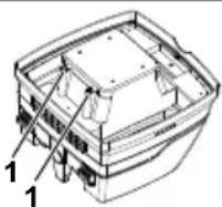
Clean the water level sensors (1) regularly and examine for signs of damage.
▶ Vacuum cleaning without paper filter bags.
The folding filter cassettes are designed for wet vacuum cleaning.
The fitted sensor switches the motor off when the container is full. The handling of the vacuum cleaner can be compromised by a full container.
▶ Empty the vacuum clean(see "6 Emptying the container").
⚠️ CAUTION!
If the vacuum cleaner is not switched off, the re-start protection unit remains operative. Only after switching off and re-starting is the vacuum cleaner ready for use again.
Remove the suction hose from the liquid before emptying.
After switching off, a small quantity of water can flow back out of the hose, as a result of the high suction level and the favourable flow condition in the container.
▶ If you use it as a dry vacuum cleaner, you must insert dry filters.
NOTE
If you change between dry and wet vacuum cleaning frequently, we recommend using a second set of filters, preferably polyester folding filter cassettes.
5 Cleaning the fi Iter
The suction unit is fitted with an electro-magnetic filter cleaning device which can shake off any dust adhered to the folded filter cassettes.
5.1 Cleaning the fi Iter
The vibration function (switch setting R or RA / switch ②a) should be activated at the latest when the volume flow display ②c (warning lamp) lights up or when the warning signal sounds or when the suction output sinks.
5.2 Automatic cleaning
Filter cleaning is performed (switch setting RA/switch ②a) automatically during the next working break when the minimum volume flow level is reached.
6 Emptying the container
NOTE
Only permitted for dust with AGW's > 1mg/m ^3
Switch the vacuum cleaner off, pull the mains plug out.
▷ Open the latches.
Remove the cover and suction hose from the container.
▶ Empty the container by pouring out.
6.1 Dispose of the fleece filter bag
▶ Pull the mains plug out.
▶ Fit mouth protection.
Remove suction hose, close off the suction spigot with a plug*.
▶ Open the side latches, remove the top section.
Carefully pull the flange off the suction spigot and close off the flange.
▷ Dispose of the vacuumed up material in accordance with legal requirements.
6.2 Dispose of the PE emptying and disposal bag
PE emptying and disposal bag: Switch the vacuum cleaner on, shake the folding filter cassettes. Switch off the vacuum cleaner.
▶ Fit mouth protection.
Remove suction hose, close off the suction spigot with a plug*.
▶ Open the side latches, remove the top section.
Before setting aside the top section, switch to >1< position, to draw up any floating dust which may exist.
- Close off the PE emptying and disposal bag carefully with the tape provided.
▶ Carefully pull the flange off the suction spigot and close it off
Remove the PE emptying and disposal bag carefully from the container
▷ Dispose of the vacuumed up material in accordance with legal requirements.
6.3 Insert fleece filter bag
NOTE
Only use fleece filter bags for dry vacuum cleaning.
6.3.1 RP500YDM
▶ Slide the flange completely over the suction aperture.
NOTE
Operating the rotary slider\*
▶ Push the rotary slider* from the inside to the outside, turn through 180° (see mark) and then push inwards again from the outside through the suction spigot
Place the rotary slider* in the suction aperture with the mark
▲ pointing upwards.
Place the upper section on the container and close the side latches.
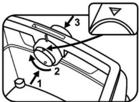
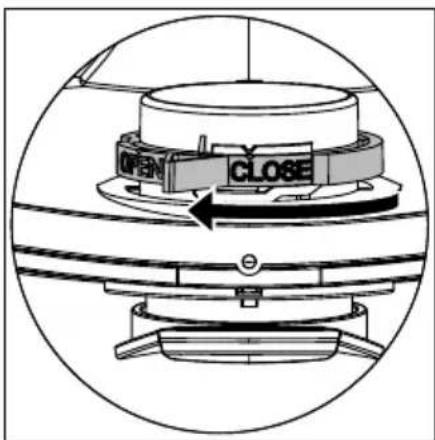
6.3.2 RP250YDM
▶ Slide the flange completely over the suction aperture.
NOTE
Operating the rotary slide
Turn the red rotary slide inside to position CLOSE to the stop on the marker ▲.
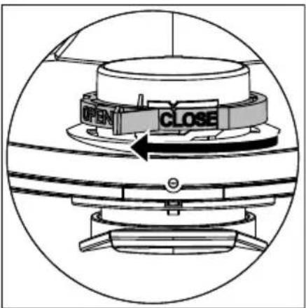
Place the upper section on the container and close the side latches.
(* depending on the equipment variant)
6.4 Insert PE emptying and disposal bag\*
NOTE
Only the vacuum cleaners class M and H with special containers and rotary slider in the suction aperture of types RP250YDM and RP500YDM are suitable for the use of PE Emptying and disposal bags.
6.4.1 RP500YDM
NOTE
Operating the rotary slider\*
▶ Push the rotary slider* from the inside to the outside, turn through 180° (see mark) and then push inwards again from the outside through the suction spigot
- Place the rotary slider* in the suction aperture with the mark ● pointing upwards.
▶ Slide the flange completely over the suction aperture and place the upper bag opening over the edge of the container.
Place the upper section on the container and close the side latches.
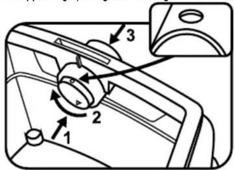
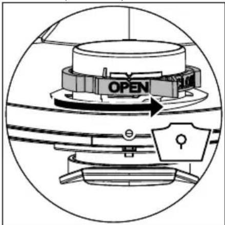
6.4.2 RP250YDM
NOTE
Operating the rotary slide
Turn the red rotary slide inside to position OPEN to the stop on the marker ▲.
Slide the flange completely over the suction aperture and place the upper bag opening over the edge of the container.
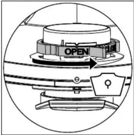
Place the upper section on the container and close the side latches.
(* depending on the equipment variant)
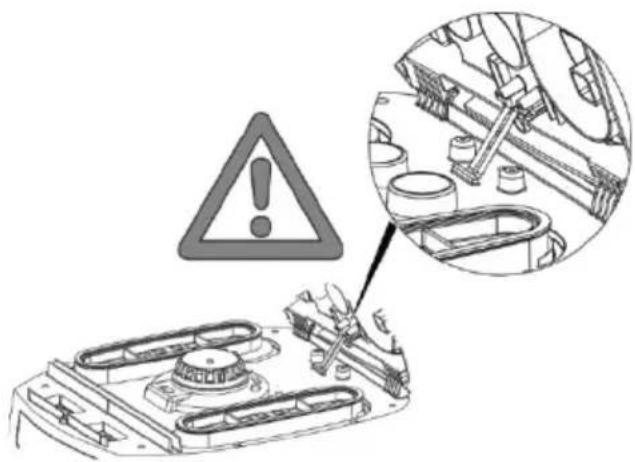
7 Changing the fi Iter
7.1 Changing the folding fi Iter
▶ Shake the folding filter cassettes before changing them.
Turn the lock on the latch through 90° in a counter-clockwise direction with a coin or similar object and push the latch to the rear.
▷ Fold the hood up
Immediately isolate the folding filter cassettes that you have removed in a dust-tight plastic bag and dispose of properly in accordance with the stipulations.
▶ Insert new folding filter cassettes.
Lift the locking bracket up, fold the hood down and click in place with light pressure.
8 Changing the motor protection fi Iter
NOTE
If the motor protection filter is contaminated this indicates defective filter cassettes.
▶ Replacing the folding filter cassettes.
Replace the motor protection filter or wash the motor protection filter under flowing water, dry and re-insert.
9 Transport
Insert the closing plug* of the vacuum cleaner into the suction aperture.
The motor head must be securely fixed to the container (close the latches).
Place the accessories in a suitable plastic bag and seal the plastic bag or place it in the tool storage compartment.
Plug the ends of the suction hose into each other.
Place the hose around the vacuum cleaner and clamp onto the handle.
10 Maintenance
NOTE
Switch the vacuum cleaner off and pull out the mains plug before any maintenance work.
For maintenance by the user, the vacuum cleaner must be
- dismantled,
- cleaned and
- maintained,
as far as possible without creating any danger to the maintenance personnel or other.
Precautionary measures
Suitable precautionary measures include
- Cleaning before dismantling,
- Provide local filtered positive ventilation where the vacuum cleaner is to be dismantled,
- Clean the maintenance area and
- suitable personal protection equipment.
Precautionary measures with vacuum cleaners class H and M
The outside of the vacuum cleaner should be cleaned and wiped down or should be treated with a sealing agent before being removed from the dangerous area. All parts of the vacuum cleaner must be considered to be contaminated when they are removed from the danger area and suitable handling must be used to prevent dust distribution.
Contaminated items
When carrying out maintenance or repair work, all contaminated items which have not been adequately cleaned must be disposed of. Such items must be disposed of in impermeable bags in accordance with the applicable regulations concerning the disposal of such waste.
Testing the effectiveness of the vacuum cleaner
NOTE: In addition, the effectiveness of the vacuum cleaner class H must be checked at least once a year.
There must be an adequate air exchange rate L in the room if the exhaust air returns to the room. Further information can be taken from your national regulations.
If the suction of the vacuum cleaner reduces and the cleaning procedure of the folding filter cassettes increases, the suction performance is not adequate (provided that the container is empty and the fleece filter bag has been replaced) then it is necessary to replace the folding filter cassettes.
10.1 Cleaning
NOTE
Acids, alkalis and solvents can corrode the vacuum cleaner parts.
▷ Clean the container and accessories with water.
Wipe the top section with a damp cloth.
▶ Allow the container and accessories to dry.
10.2 Repair
⚠ DANGER!
▶ Inappropriately repaired vacuum cleaners present a danger to the operator.
▶ Have repairs carried out by specialists, e. g. customer service. Use only genuine spare parts.
11 First aid in the event of a fault
| NOTE | ||
| Malfunctions cannot always be traced back to defects in the vacuum cleaner. | ||
| Fault Possible cause Remedy | ||
| Reduction in suction Filter contaminated Clean. | ||
| fl eece fi Iter full Change. | ||
| Container full Empty. | ||
| Nozzle, pipes or hose blocked Clean. | ||
| Vacuum cleaner will not start Mains plug plugged in? | ||
| Mains power missing? | ||
| Mains cable OK? | ||
| Cover closed properly? | ||
| Water sensor switched off? | ||
| Vacuum cleaner in readiness for operation "RA"? | ||
| The vacuum cleaner does not start when the tool is switched on in the >RA< mode | Is the mains plug of the unit in the plug socket? | Put the mains plug in the vacuum cleaner plug socket |
| Solenoid valve of compressed air automatic switch-on* contaminated? | Flush the compressed air automatic switch-on* with alcohol | |
| PE emptying and disposal bag is sucked against the fi Iter | Position of rotary slider incorrect | Set rotary slider to ● position or OPEN (see "6.4 Insert PE emptying and disposal bag"). |
| Vacuum cleaner classes M or H: with inserted fleece filter bag dust in filter | Position of rotary slider incorrect | Set rotary slider to ▲ position or CLOSE (see "6.3 Insert fleece filter bag"). |
Do not take any other action and contact the customer service workshop.
12 Genuine accessories
| NOTE | ||
| Use genuine accessories. | ||
| Article designation Properties/material Order quantity | (1 set) | |
| Fleece filter bag FBV35 | for 30 litre plastic container, IFA class M approved | 5 Number |
| Filter cassette FK 4300 | Cellulose material, IFA class M approved | 2 Number |
| Filter cassette FKP 4300 | Polyester material, IFA class M approved | 2 Number |
| Filter cassette FKP 4300 HEPA (H 14) | 3 layer filter cassette, IFA class H approved | 2 Number |
| PE emptying and disposal bag | only for RP vacuum cleaners class M and H | 5 Pieces |
13 Technical Data
| RP250YDM RP500YDM | |||
| Voltage V ~ 220–240 220–240 | |||
| Frequency Hz 50/60 50/60 | |||
| Rated power W 1200 1200 | |||
| Max. power W 1400 1400 | |||
| Air flow* m3/h 151 151 | |||
| Air flow** | m3/h 263 263 | ||
| Negative pressure* | hPa | 235 235 | |
| Negative pressure** | hPa | 270 270 | |
| Noise level | dB (A) | 69.5 | 69.5 |
| L x W x H | cm | 45 x 39 x 53 | 59.5 x 46.5 x 96 |
| Weight | kg | 11.0 | 16.0 |
| Filter surface | cm2 | 8400 8400 | |
* at the hose, ** at the fan
Connection line on vacuum cleaners with plug socket: H07RN-F 3G 1.5
14 Tests and approvals
Electro-technical tests must be carried out in accordance with the accident prevention regulations (BGV A3) and in accordance with DIN VDE 0701 Part 1 and Part 3. These tests are required in accordance with DIN VDE 0702 at regular intervals and after repair or modification.
The vacuum cleaners are successfully tested in accordance with IEC/EN 60335-2-69.
NOTE
Old equipment contains valuable materials which are designed for re-processing. The vacuum cleaners must not be thrown away in the normal household waste, but should be disposed of at a suitable proper collection system, e. g. via your communal disposal location.
GUARANTEE
We guarantee HiKOKI Power Tools in accordance with statutory/ country specific regulation. This guarantee does not cover defects or damage due to misuse, abuse, or normal wear and tear. In case of complaint, please send the Power Tool, undismantled, with the GUARANTEE CERTIFICATE found at the end of this Handling instruction, to a HiKOKI Authorized Service Center.
Français
▶ Stekker in stopcontact steken
FARE!
Sæt overdelen på beholderen og luk lukkemekanismerne i siden.
6.3.2 RP250YDM
Sæt overdelen på beholderen og luk lukkemekanismerne i siden.
Sæt overdelen på beholderen og luk lukkemekanismerne i siden.
6.4.2 RP250YDM
BEMÆRK
6.1 Bortskaff fleece-filterposen
▷ Sett inn nye foldefilterkassetter.
▶ Horný diel nasad'te na nádobu a zatvorte bočné uzávery.
6.4.2 RP250YDM
POZNÁMKA
2 Elementi za prikaz in upravljanje
Zgornji del postavite na posodo in zaprite stranska zapirala.
6.3.2 RP250YDM
- Prirobnico potisnite do konca preko sesalne odprtine.
OPOMBA
Upravljanje vrtljivega drsnika
Rdeči vrtljivi drsnik zavrtite v položaj CLOSE, da se ustavi na označevalniku ▲.
Zgornji del postavite na posodo in zaprite stranska zapirala.
6.4.2 RP250YDM
OPOMBA
Upravljanje vrtljivega drsnika
Rdeč vrtljivi drsnik zavrtite v položaj OPEN, da se ustavi na označevalniku ▲.
2 Elementi prikaza i rukovanja
Odaberite sljedeće funkcije i postavke:
| 0 | Usisivač isključen | - Utičnica pod naponom |
| I Usisivač uključen | - Utičnica pod naponom- Isključena automatska funkcija trešnje | |
| A | Pogonska spremnost za automatiku uključivanja/isključivanja | - Usisivač uključuje i isključuje električni alat. |
| RA | Pogon pripravnosti | - Pogon radne spremnosti kao „A“ plus Automatsko čišćenje filtra. |
| Automatska funkcija trešnje | - Ovo čišćenje filtra slijedi automatski u idućoj radnoj stanki nakon što se dostigne podešena najmanja prostorna struja (položaj sklopke RA/sklopka 2a). | |
| Prikaz prostorne struje | - Kod pune posude i/ili začepljenosti na usisnom crijevu upali se lampica prikaza punjenja. Kod usisivača klase M i H dodatno se može čuti akustični signal. | |
| Reguliranje promjera usisnog crijeva | - Odredite maksimalne vrijednosti podtlaka za automatsku trešnju. | |
3 Puštanje u pogon
Stavite gornji dio na posudu i zatvorite bočne zatvarače.
6.3.2 RP250YDM
Stavite gornji dio na posudu i zatvorite bočne zatvarače. (*ovisno o varijanti opreme)
Stavite gornji dio na posudu i zatvorite bočne zatvarače.
6.4.2 RP250YDM
NAPOMENA
Upravljanje okretnim kliznikom
Okrenite crveni okretni kliznik u položaj OPEN dok se ne zaustavi na oznaci ▲.
Prirubnicu potpuno navucite preko otvora za usisavanje, gornji otvor vrečice stavite preko ruba posude.
Stavite gornji dio na posudu i zatvorite bočne zatvarače. (*ovisno o varijanti opreme)
7 lzmijenite filter
7.1 Izmijenite nabrani filter
- Primje izmjene filtera protresite kasete za nabrani filter.
Zatvor na zaporu pomoću novčanice ili sličnog predmeta okrenite 90° suprotno od kazaljke sata i pritisnite zapor prema natrag.
Otvorite haubu
Izvađene kasete za nabrani filter odmah zatvorite u plastičnu vrečicu otpornoj na prašinu te uklonite prema propisima.
▷ Stavite nove kasete za nabrani filter.
Podignite držak brave, spustite haubu i zatvorite ju laganim pritiskom.
8 lzmijenite filter za zaštitu motora
UPUTA
Ukoliko je filter za zaštitu motora prljav, znak je defektne kasete za nabrani fi Iter.
Zamijenite kasete za nabrani filter.
Zamijenite filter za zaštitu motora odnoso isperite filter za zaštitu motora ispod tekuće vode, osušite ga i ponovo ga stavite.
9 Transport
Čep zatvarača* usisivača stavite u usisni otvor.
Glava motora mora biti dobro povezana s posudom (zatvoriti zatvarače).
Pribor stavite u prikladne plastične vrečice i zatim zatvorite plastične vrečice odnosno stavite ih u depot alata.
Kraj usisnog crijeva i početak usisnog crijeva spojite.
▶ Crijevo stavite oko usisivača i utisnite na ručci.
10 Održavanje
UPUTA
Operating the rotary slide
Class L vacuum devices are suitable for aspiration/clearing of dry, non-combustible dusts and hazardous dusts with occupational exposure limit values (AGW) > 1 mg/m ^3 .
Class M vacuum devices are suitable for aspiration/clearing of dry, non-combustible dusts, non-combustible liquids, wood dusts and hazardous dusts with workplace limit values of ≥ 0.1 mg/m ^3 .
natural_image
Line drawing of a quill pen with inkwell (no text or symbols)| Deutsch Dansk Magyar | ||||
| GARANTIESCHEIN1 Modell-Nr.2 Serien-Nr.3 Kaufdatum4 Name und Anschrift des Kunden5 Name und Anschrift des Händlers (Bitte mit Namen und Anschrift des Handlers abstempeln) | GARANTIBEVIS1 Modelnummer2 Serienummer3 Købsdato4 Kundes navn og adresse5 Forhandlers navn og adresse (Indsæt stempel med forhandlers navn og adresse) | GARANCIA BIZONYLAT1 Tipusszám2 Sorozatszám3 A vásárlás dátuma4 A Vásárló neve és címe5 A Kereskedő neve és címe (Kérjük ide elhelyezni a Kereskedő nevének és címének pecsétjét) | ||
| English Svenska Čeština | ||||
| GUARANTEE CERTIFICATE1 Model No.2 Serial No.3 Date of Purchase4 Customer Name and Address5 Dealer Name and Address(Please stamp dealer name and address) | GARANTICERTIFIKAT1 Modellnr2 Serienr3 Inköpsdatum4 Kundens namn och adress5 Försäljarens namn och adress (Stämpla försäljarens namn och adress) | ZÁRUČNÍ LIST1 Model č.2 Série č.3 Datum nákupu4 Jméno a adresa zákazníka5 Jméno a adresa prodejce (Prosíme o razitko se jménem a adresou prodejce) | ||
| Français Norsk Slovenčina | ||||
| CERTIFICAT DE GARANTIE1 No. de modèle2 No de série3 Date d'achat4 Nom et adresse du client5 Nom et adresse du revendeur(Cachet portant le nom et l'adresse du revendeur) | GARANTISERTIFIKAT1 Modellnr.2 Serienr.3 Kjøpsdato4 Kundens navn og adresse5 Forhandlerens navn og adresse (Vennligst stemple forhandlerens navn og adresse) | ZÁRUČNÝ LISTA1 Č. modelu2 Sériové č.3 Dátum zakúpenia4 Meno a adresa zákazníka5 Názov a adresa predajcu (Pečiatka s názvom a adresou predajcu) | ||
| Español Suomi Română | ||||
| CERTIFICADO DE GARANTÍA1 Número de modelo2 Número de serie3 Fecha de adquisición4 Nombre y dirección del cliente5 Nombre y dirección del distribudor(Se ruega poner el sello del distribudor con su nombre y dirección) | TAKUUTODISTUS1 Malli nro2 Sarja nro3 Ostopáivämäärä4 Asiakkaan nimi ja osoite5 Myyján nimi ja osoite(Leimaa myyján nimi ja osoite) | CERTIFICAT DE GARANTIE1 Model nr.2 Nr. de serie3 Data cumpărării4 Numele și adresa clientului5 Numele și adresa distributorului (Vă rugăm aplicați štampila cu numele și adresa distribuitorului) | ||
| Português Ελληνικά Slovenščina | ||||
| CERTIFICADO DE GARANTIA1 Número do modelo2 Número do série3 Data de compra4 Nome e morada do cliente5 Nome e morada do distribuidor(Por favor, carimbe o nome e morada do distribuidor) | ПІЗТОПОІНТИКО ЕГГУНЕНЗ1 Ap. Movтėlou2 Aùξων Ap.3 Нμερομηνία αγοράς4 Овюμα και διεύθυνση πελάτη5 Овюμα και διεύθυνση μεταπωλητή (Παρακαλούμε να χρησιμοποιηθεί σφραγίδα) | GARANCIJSKO POTRDILO1 Št. modela2 Serijska št.3 Datum nakupa4 Ime in naslov kupca5 Ime in naslov prodajalca (Prosimo vtisnite žig z imenom in naslovom prodajalca) | ||
| Italiano Türkge Hrvatski | ||||
| CERTIFICATO DI GARANZIA1 Modello2 N° di serie3 Data di acquisto4 Nome e indirizzo dell'acquirente5 Nome e indirizzo del rivenditore(Si prega di apporre il timbro con questi dati) | GARANTI SERTÍFÍKASI1 Model No.2 Seri No.3 Satin Alma Tarihi4 Müşteri Adi ve Adresi5 Bayi Adi ve Adresi (Lütfen bayi adini ve adresini kaşe olarak basin) | JAMSTVENI CERTIFIKAT1 Br modela.2 Serijski br.3 Datum kupnje4 Ime i adresa kupca5 Ime i adresa trgovca (Molimo stavite pečat na ime i adresu trgovca) | ||
| Nederlands Polski Български | ||||
| GARANTIEBEWIJS1 Modelnummer2 Serienummer3 Datum van aankoop4 Naam en adres van de gebruiker5 Naam en adres van de handelaar(Stempel a.u.b. naam en adres vande de handelaar) | GWARANCJA1 Model2 Numer seryjny3 Data zakupu4 Nazwa klienta i adres5 Nazwa dealera i adres (Pieczęć punktu sprzedaży) | ГАРАНЦИОНЕН СЕРТИФИКАТ1 Модел No2 Сериен No3 Дата за закупуване4 Име и адрес на клиента5 Име и адрес на търговеца (Моля, отпечатайте името и адрес на дильра) | ||
HiKOKI
| 1 | |
| 2 | |
| 3 | |
| 4 | |
| 5 |
Siemensring 34, 47877 willich, Germany
Tel: +49 2154 49930
Fax: +49 2154 499350
URL: http://www.hikoki-powertools.de
Hikoki Power Tools Netherlands B.V.
Brabanthaven 11, 3433 PJ Nieuwegein, The Netherlands
Tel: +31 30 6084040
Fax: +31 30 6067266
URL: http://www.hikoki-powertools.nl
Hikoki Power Tools (U.K.) Ltd.
Precedent Drive, Rooksley, Milton Keynes, MK 13, 8PJ,
United Kingdom
Tel: +44 1908 660663
Fax: +44 1908 606642
URL: http://www.hikoki-powertools.uk
Hikoki Power Tools France S.A.S.
Hikoki Power Tools Belgium N.V./S.A.
Koningin Astridlaan 51, B-1780 Wemmel, Belgium
Tel: +32 2 460 1720
Fax: +32 2 460 2542
URL http://www.hikoki-powertools.be
Hikoki Power Tools Italia S.p.A
Via Piave 35, 36077, Altavilla Vicentina (VI), Italy
Tel: +39 0444 548111
Fax: +39 0444 548110
URL: http://www.hikoki-powertools.it
Hikoki Power Tools Ibérica, S.A.
C/ Puigbarral, 26-28, Pol. Ind. Can Petit, 08227 Terrassa
(Barcelona), Spain
Tel: +34 93 735 6722
Fax: +34 93 735 7442
URL: http://www.hikoki-powertools.es
Kjeller Vest 7, N-2007 Kjeller, Norway
Tel: (+47) 6692 6600
Fax: (+47) 6692 6650
URL: http://www.hikoki-powertools.no
Hikoki Power Tools Sweden AB
Rotebergsvagen 2B SE-192 78 Sollentuna, Sweden
Tel: (+46) 8 598 999 00
Fax: (+46) 8 598 999 40
URL: http://www.hikoki-powertools.se
Hikoki Power Tools Denmark A/S
Lillebaeltsvej 90, 6715 Esbjerg N, Denmark
Tel: (+45) 75 14 32 00
Fax: (+45) 75 14 36 66
URL: http://www.hikoki-powertools.dk
Hikoki Power Tools Finland Oy
Tupalankatu 9, 15680 Lahti, Finland
Tel: (+358) 20 7431 530
Fax: (+358) 20 7431 531
URL: http://www.hikoki-powertools.fi
Hikoki Power Tools Hungary Kft.
Hikoki Power Tools Romania S.R.L.
Ring Road, No. 66, Mustang Traco Warehouses, Warehouse
No.1, Pantelimon City, 077145, Ilfov County, Romania
- ⚠️ GEFAHR!
- ⚠️ DANGER!
- WARNING!
- ⚠ WARNING!
- Before use
- Indicator and operating elements
- Commissioning
- Switching on and off
- ⚠️ CAUTION!
- NOTE
- Selector switch for minimum material flow (horn and light) on vacuum cleaners classes "M" and "H"
- Operating modes
- Dry vacuum cleaning
- Wet vacuum cleaning
- Cleaning the fi Iter
- Cleaning the fi Iter
- Automatic cleaning
- Emptying the container
- Dispose of the fleece filter bag
- Dispose of the PE emptying and disposal bag
- Insert fleece filter bag
- RP500YDM
- Operating the rotary slider\*
- RP250YDM
- Operating the rotary slide
- Insert PE emptying and disposal bag\*
- RP500YDM
- RP250YDM
- Changing the fi Iter
- Changing the folding fi Iter
- Changing the motor protection fi Iter
- Transport
- Maintenance
- Precautionary measures
- Precautionary measures with vacuum cleaners class H and M
- Contaminated items
- Testing the effectiveness of the vacuum cleaner
- Cleaning
- Repair
- ⚠ DANGER!
- First aid in the event of a fault
- Genuine accessories
- Tests and approvals
- GUARANTEE
- Français
- FARE!
- BEMÆRK
- Bortskaff fleece-filterposen
- POZNÁMKA
- Elementi za prikaz in upravljanje
- OPOMBA
- Upravljanje vrtljivega drsnika
- Elementi prikaza i rukovanja
- Puštanje u pogon
- NAPOMENA
- Upravljanje okretnim kliznikom
- lzmijenite filter
- Izmijenite nabrani filter
- lzmijenite filter za zaštitu motora
- UPUTA
- Održavanje
- Hikoki Power Tools Netherlands B.V.
- Hikoki Power Tools (U.K.) Ltd.
- Hikoki Power Tools France S.A.S.
- Hikoki Power Tools Belgium N.V./S.A.
- Hikoki Power Tools Italia S.p.A
- Hikoki Power Tools Ibérica, S.A.
- Hikoki Power Tools Sweden AB
- Hikoki Power Tools Denmark A/S
- Hikoki Power Tools Finland Oy
- Hikoki Power Tools Hungary Kft.
- Hikoki Power Tools Romania S.R.L.
Brand : HiKOKI
Model : RP250YDM
Category : Paint spray