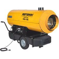
BV 400 - Heating Master - Free user manual and instructions
Find the device manual for free BV 400 Master in PDF.


| Product type | Mobile hot air heater (direct or indirect model) |
| Recommended use | Professional, temporary for medium or large spaces |
| Authorized fuel | Diesel or kerosene |
| Power supply | 230 V / 50 Hz (check rating plate) |
| Operating modes | Heating (full power or half power) and ventilation only |
| Ignition | Electronic, with manual reset button |
| Room thermostat | Compatible (optional, connect to terminal block provided) |
| Flue gas evacuation | Direct models: discharge into the room; indirect models: can be ducted outside |
| Safety | Automatic shutdown in case of anomaly, overheat protection, flame detection |
| Filters | Filling filter (in tank) and suction filter (depending on model) |
| Preventive maintenance | Annual cleaning of filters and tank; drain before prolonged storage |
| Reparability | Original spare parts; repair by authorized technical assistance center |
| Transport and storage | Drain the tank, keep level, store dry |
| Included accessories | Wheels, handle, chimney (depending on model) |
| Minimum safety distance | 1.5 m from side walls, 2.5 m from air outlet |
Frequently Asked Questions - BV 400 Master
User questions about BV 400 Master
0 question about this device. Answer the ones you know or ask your own.
Ask a new question about this device
Download the instructions for your Heating in PDF format for free! Find your manual BV 400 - Master and take your electronic device back in hand. On this page are published all the documents necessary for the use of your device. BV 400 by Master.
USER MANUAL BV 400 Master
natural_image
Icon of an open book with an exclamation mark, enclosed in a diamond shape with a yellow diagonal stripe (no text or symbols)USER AND MAINTENANCE MANUAL
BV 400
| en | it | de | es | fr | nl | pt | da | fi | no | sv | pl | ru | cs | hu | sl | tr | hr | lt |
| lv | et | ro | sk | bg | uk | bs | el | zh | kk |
NOTE:
TECHNICAL DATA TABLE - TABELLA DATI TECNICI - TECHNISCHE DATENTABELLE - TABLA DE DATOS TÉCNICOS - TABLEAU DES DONNÉES TECHNIQUES - TABEL TECHNISCHE GEGEVENS - TABELA DE DADOS TÉCNICOS - TEKNISK DATATABEL - TEKNISTEN TIETOJEN TAULUKKO - TABELL FOR TEKNISKE DATA - TABELL MED TEKNISKA EGENSKAPER - TABELA DANYCH TECHNICZNYCH - ТАБЛИЦЕ ТЕХНИЧЕСКИХ ДАННЫХ - TABULKA TECHNICKÝCH ÚDAJŮ - MŰSZAKI ADATOK ТАВЛАЗАТА - TEHNIČNI PODATKI - TEKNÍK VERİLER TABLOSUNDA - TABLICI S TEHNIČKIM PODACIMA - TECHNINIŲ DUOMENŲ LENTELEJE - TEHNISKO DATU TABULA - TEHNILISTE ANDMETE TABEL - TABELUL CU DATE TEHNICE - ТАВУЛКА TECHNICKÝCH ÚDAJOV - ТАБЛИЦА ТЕХНИЧЕСКИ ДАННИ - ТАБЛИЦІ ТЕХНИЧНИХ ДАНИХ - TABELI SA ТЕННИČKIM PODACIMA - ПІNAKІДА ТОН ТЕХНИКΩΝ ΣΤΟΙΧΕΙΩΝ - 技术参数 - ТЕХНИКАЛЫҚ КОРСЕТКІШТЕР КЕСТЕСІ
| MODEL BV 400 | ||
| ### | ### | |
 | 80 kW-кВт68.800 kcal/h-ккал/ч273.000 Btu/h-БТЕ/ч | 110 kW-кВт94.600 kcal/h-ккал/ч375.000 Btu/h-БТЕ/ч |
 | 6,3 kg/h-кг/ч 8,4 kg/h-кг/ч | |
 | DIESEL-HVO100-KEROSENEDизель-HVO100-керосин | |
 | 150 l-л | |
 | 6.200 m3/h-m3/ч | |
 | ~220-240 V-B (-15% ÷ +10%) 50 Hz-Гц 6,8 A 1,43 kW-кВт | |
 | 200 kg-кг | |
 | 1.75 GpH 60°S DANFOSS | |
 | 900 kPa-кПа9 bar-6ap | 1.600 kPa-кПа16 bar-6ap |

IMPORTANT: In order to have a correct function you must use an electrical generator in class G3 or more (frequency variation ±1%, tension variation ±2%). The maximum power of electrical generator must be three time the nominal power of device that you must connect.
NOTE:
PICTURES - FIGURE - ABBILDUNGEN - FIGURAS - FIGURES - FIGUREN - FIGURAS - FIGURER - KUVAT - FIGURER - FIGUR - RYSUNKI - РИСУН- КИ - OBRÁZKY - ÁBRÁK - SLIKE - ŞEKİLLER - SLIKE - PAVEIKSLÉLIAI - ATTĚLI - JOONISED - IMAGINI - OBRÁZKY - ФИГУРА - МАЛЮНКИ - SLIKE - EIKONEΣ - 图 - СУРЕТТЕР
natural_image
Line drawing of a cylindrical industrial machine with control panel and wheels (no text or symbols)1

natural_image
Technical line drawing of a cylindrical industrial device with attached piping and housing (no text or symbols)2
PICTURES - FIGURE - ABBILDUNGEN - FIGURAS - FIGURES - FIGUREN - FIGURAS - FIGURER - KUVAT - FIGURER - FIGUR - RYSUNKI - РИСУН- КИ - OBRÁZKY - ÁBRÁK - SLIKE - ŞEKİLLER - SLIKE - PAVEIKSLÈLIAI - ATTËLI - JOONISED - IMAGINI - OBRÁZKY - ФИГУРА - МАЛЮНКИ - SLIKE - EIKONEΣ - 图 - СУРЕТТЕР

flowchart
graph TD
    A["Start"] --> B["Process 1"]
    B --> C["Process 2"]
    C --> D["Process 3"]
    D --> E["End"]





PICTURES - FIGURE - ABBILDUNGEN - FIGURAS - FIGURES - FIGUREN - FIGURAS - FIGURER - KUVAT - FIGURER - FIGUR - RYSUNKI - РИСУН- КИ - OBRÁZKY - ÁBRÁK - SLIKE - ŞEKİLLER - SLIKE - PAVEIKSLÉLIAI - ATTĚLI - JOONISED - IMAGINI - OBRÁZKY - ФИГУРА - МАЛЮНКИ - SLIKE - EIKONEΣ - 图 - СУРЕТТЕР

natural_image
Technical line drawing of a mechanical component emitting particles from a nozzle (no text or symbols)

NOTE:
IMPORTANT: READ AND UNDERSTAND THIS MANUAL PRIOR TO ASSEMBLING, STARTING UP OR CONDUCTING MAINTENANCE ON THIS HEATER. USING THE HEATER INCORRECTLY CAN CAUSE SERIOUS INJURY. KEEP THIS MANUAL FOR FURTHER REFERENCE.
1. DESCRIPTION
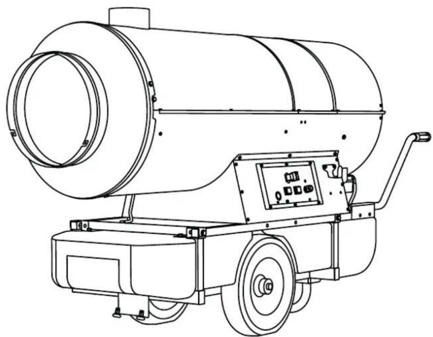
This series of heaters is particularly suited to heating medium to large-sized rooms or areas. Thanks to a heat exchanger, indirect heaters (PIC. 1) separate combustion gases from the hot air released into the environment. This way it is possible to introduce a flow of clean hot air in the area that needs to be heated up and direct exhaust fumes outside.
These heaters have been designed in line with the most recent safety, operating and duration criteria. The safety devices ensure the machine always operates correctly.
2. SAFETY INFORMATION WARNINGS

IMPORTANT: Do not use the heater for living areas, in any case, refer to onal regulations.

IMPORTANT: The air heater is designed professional, mobile and temporary ications. It is not intended for domestic nor for the thermal comfort of persons.

IMPORTANT: The heater is not suitable for use by persons (including children) with reduced physical, sensory and mental capabilities, or inexperienced persons, unless they are supervised by a person responsible for their safety. Children must be supervised to ensure that they do not play with the heater.

IMPORTANT: The manufacturer accepts liability for damage to property or personal ry caused by unauthorised modifications the heater.

DANGER: Improper use of this heater can see damage or danger to life, injury, burns, corrosion, electric shock or poisoning. The symptoms of carbon monoxide asphyxia resemble those of influenza, with headaches, illness and/or nausea. Such symptoms could be caused by faulty operation of the ter. IF THESE SYMPTOMS OCCUR, GO TDOORS IMMEDIATELY and have the ter repaired by a technical support centre.

DANGER: The heater, when controlled room thermostat (where provided), can ch on at any time.
▶▶2.1. GENERAL:
▶2.1.1. Observe all local legislation and current regulations when using the heater.
▶2.1.2. Heaters used in the vicinity of tarpaulins, curtains or other similar materials must respect the minimum safety distance. In any case, comply with all local legislation and current regulations.
▶2.1.3. Never use the heater in environments where flammable elements are present.
▶2.1.4. Keep children and animals at a safe distance from the heater.
▶2.1.5. The minimum recommended safety distance between the heater and flammable elements, including the power cable, is 1.5 m (3.2 ft) and 2.5 m (8.2 ft) from the air outlet.
▶2.1.6. Before putting the heater into operation, make sure that the fire-fighting devices are ready for use.
▶2.1.7. The heater must be used in well-ventilated areas.
▶2.1.8. The heater must be used on stable and level surfaces.
▶2.1.9. Electrically supply the heater only with current having the voltage and frequency specified on the identification plate attached to the product.
▶2.1.10. Electrically supply the heater only with electric extension cords of a suitable cross-section, properly earthed.
▶2.1.11. Do not block or partialise the air inlet and outlet of the heater.
▶2.1.12. Disconnect the heater from the power supply when the product is not used for an extended period of time.
▶2.1.13. When the heater is hot, or connected to the power supply, or in operation, it must never be moved, handled, refilled or subjected to any maintenance work.
▶2.1.14. Any repair work on the heater must be carried out by the technical support centre.
▶2.1.15. Use only original spare parts, strictly observing the basic configuration.
▶2.1.16. Only apply original kits to the heater.
▶▶2.2. REFUELLING:
▶2.2.1. Only refuel the heater with the type of fuel specified on the identification plate attached to the product.
▶2.2.2. Switch off and wait for the heater to cool down completely before refuelling.
▶2.2.3. Personnel responsible for refuelling the heater must be careful and use the appropriate safety devices.
▶2.2.4. Fuel must be stored in accordance with current regulations.
▶2.2.5. All fuel tanks must be at a minimum safe distance from the heater, according to current regulations.
3. UNPACKING
WARNING: The packaging material is not a toy. Keep the plastic bag out of the reach of children; danger of suffocation!
▶3.1. Remove all packaging materials used to wrap and deliver the heater and dispose them in compliance with current regulations.
▶3.2. If the heater is placed on a moving platform, make sure it is moved gently.
▶3.3. Check for any damage that might have happened during transport. If the heater looks damaged, immediately inform the dealer from which it was purchased.
4. ASSEMBLY
These heaters are fitted with wheels, a handle and a chimney depending on the model (PIC. 2). These parts, which come with the relative nuts and bolts, are in the heater's packaging.
5. FUEL
WARNING: The heater only works with DIESEL or KEROSENE.
In order to avoid explosions or any fire hazards, use only diesel or kerosene fuel.
Never use petrol, naphtha, paint solvents, alcohol or any other highly inflammable fuels.
Non-toxic, anti-freeze additives can be used in case of very low temperatures.
It is advisable to use winter diesel below 5°C.
6. OPERATING PRINCIPLES
A. Combustion chamber and burner, B. Fan, C. Motor, D. Pump, E. Tank, F. Chimney.
The pump draws fuel from the tank and brings it to the operating pressure. The fuel is brought to the nozzle that sprays it into the combustion chamber. The combustion is carried out with a mix of air and fuel and the flow of air generated is pushed outside via the rotation of the fan. In direct models combustion products flow together with heated air. In indirect models combustion products are directed outside through the chimney. A series of sensors connected to an electronic control board constantly keep the correct operation of the heater monitored and stops the cycle in the event of anomalies.
7. OPERATION
WARNING: Carefully read the "SAFETY INFORMATION" before switching on the heater.
▶▶7.1. SWITCHING ON THE HEATER:
▶7.1.1. Follow all the safety instructions.
▶7.1.2. Check if there is any fuel in the tank.
▶7.1.3. Close the tank cap (FIG. 3).
▶7.1.4. Connect the power plug to the mains (PIC. 4) (SEE VOLTAGE IN "TECHNICAL DATA TABLE").
▶7.1.5. Set the "ON/OFF" switch to "FLAME" (A PIC. 5). The heater should turn on within a few seconds. If the heater does not start, refer to paragraph "12." TROUBLESHOOTING".
▶7.1.6. Maximum power is achieved by setting the power switch to "DOUBLE FLAME" (B PIC. 5).
▶7.1.7. The heater can be used in ventilation mode, which is activated by setting the ON/OFF switch to "FAN" (A PIC. 5).
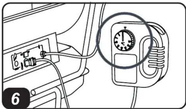
▶7.1.8. For models with a room thermostat, check the set temperature (PIC. 6).
PLEASE NOTE: IF THE HEATER SWITCHES OFF DUE TO LACK OF FUEL, TOP UP THE TANK AND RESET THE HEATER (SEE PAR. 7.2.).
IMPORTANT: In indirect models, combustion products are directed outside through suitable chimney. CARRY OUT THE CHIMNEY IN ACCORDANCE WITH CURRENT SAFETY REGULATIONS AND FOLLOW THE INSTRUCTIONS IN THE RELEVANT SECTION OF THE MANUAL.
▶▶7.2. RESETTING THE HEATER:
The appliance stops when an anomaly occurs. The reset button turns on with a steady red light (PIC. 7), it means the heater needs to be reset. To reset the heater, press the reset button all the way down (PIC. 8). Identify and remove the cause that stopped the appliance (for instance, obstruction of air intake and/or outlet, total block of the fan, etc.). Please contact an appointed service center for assistance in case it is impossible to solve the problem.
▶7.3. SWITCHING OFF THE HEATER:
Set the "1/0" button to "0" (A PIC. 5). Flames extinguish and the fan keeps on working until the combustion chamber has fully cooled down. Do not pull the plug out until the cooling cycle has totally ended.
8. CLEANING THE FILTERS
THE FILTERS MAY NEED TO BE CLEANED DEPENDING ON THE QUALITY OF THE FUEL USED.
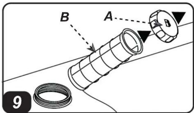
▶▶8.1. FUEL TANK FILTER (PIC. 9):
▶8.1.1. Remove tank (A) cap.
▶8.1.2. Take out the filter (B) from the tank.
▶8.1.3. Clean the filter (B) with clean fuel, without damaging it.
▶8.1.4. Put the filter (B) back in the tank.
▶8.1.5. Close cap (A).
▶▶8.2. INTAKE FILTER, (PIC. 10) DEPENDING ON THE MODEL:
▶8.2.1. Remove the cup (A).
▶8.2.2. Take out the filter (B) from the cup. Keep gaskets for later use.
▶8.2.3. Clean the filter (B) with clean fuel, without damaging it.
▶8.2.4. Put the filter (B) back in the cup.
▶8.2.5. Put the glass (A) back on and reassemble the gaskets correctly.
▶▶8.3. FUEL PUMP FILTER:
See the preventive maintenance schedule.
9. STORAGE AND
TRANSPORT
WARNING: Before moving the appliance, the heater must be stopped (SEE PAR. 7.3.) and disconnected from the power supply by pulling out the plug (PIC. 11), wait for a complete cool down and close the tank cap properly to prevent fuel leakage. Keep the heater in horizontal and stable position during transport.
IN ORDER TO KEEP THE HEATER IN THE BEST POSSIBLE CONDITIONS, WE RECOMMEND TO FOLLOW THE BELOW PROCEDURE:
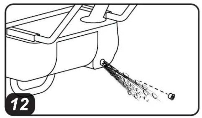
▶9.1. Empty the fuel by removing the drain cap at the bottom of the tank (PIC. 12). Dispose the fuel in an appropriate container in accordance with the current safety regulations.
▶9.2. To remove any residual remaining, pour clean fuel and rinse the tank again.
▶9.3. Close the drain cap and the tank cap.
▶9.4. In order to keep the heater in the best possible conditions, we recommend placing it in a dry and safe place.
10. CONNECTING THE ROOM THERMOSTAT
In models with a thermostat connection, remove the cap connected to the appliance and connect the room thermostat (optional) (SEE PIC. 13-14).
11. PREVENTIVE MAINTENANCE SCHEDULE
| COMPONENT MAINTENANCE FREQUENCY MAINTENANCE PROCEDURE | ||
| Fuel tank Clean once | a year or as required Empty and rinse | the tank with clean fuel (SEE PAR. 9.) |
| Filters Clean or replace | once a year or as required (make sure they are intact) | Clean the filters (SEE PAR. 8.) |
| Fuel pump filter Clean | or replace once a year or as required (make sure they are intact) | Contact a service centre |
| Electrodes Clean as | required Contact a service centre | |
| Fan Clean as required | Contact a service centre | |
| Combustion chamber | Clean as required Contact a service centre | |
12. TROUBLESHOOTING
| PROBLEM | POSSIBLE CAUSE POSSIBLE SOLUTION | |
| The heater does not start or does not operate | 1. Starter switch in “OFF” (0) position2. No power supply3. Power supply cable interrupted4. Electronic control board blocked or malfunctioning5. Incorrect setting of the room thermostat (if present)6. No fuel7. External substances or dirt in the fuel circuit | 1. Set the “ON/OFF” switch to “FLAME” (A PIC. 5)2a. Insert the power plug into the mains socket correctly (PIC. 4)2b. Check voltage of your electric supply system3. Contact a service centre4a. Reset the heater (SEE PAR. 7.2.)4b. Contact a service centre4c. Contact a service centre5. Set the room thermostat to a temperature higher than the working environment temperature (PIC. 6)6. Top up fuel and reset heater7a. Empty, rinse and refill the tank7b. Rinse the filters (SEE PAR. 8.)7c. Contact a service centre |
| Smoke while operating | 1. External substances or dirt in the fuel circuit2. Obstructed inlet air vent3. Incorrect air supply | 1a. Empty and refill the tank with clean fuel1b. Rinse fuel filters1c. Contact a service centre2. Remove all air vent obstructions3. Adjust the air damper below the fan, in the rear part of the heater (to the left, the damper closes; to the right, the damper opens) |
| The heater does not turn off | 1. Faulty electronic system 1. Contact a service centre | |
IMPORTANTE: LEGGERE E COMPRENDERE QUESTO MANUALE OPERATIVO PRIMA DI EFFETTUARE L'ASSEMBLAGGIO, LA MESSA IN FUNZIONE O LA MANUTENZIONE DI QUESTO RISCALDATORE. L'USO ERRATO DEL RISCALDATORE PUÒ CAUSARE LESIONI GRAVI O FATALI. CONSERVARE QUESTO MANUALE A TITOLO DI FUTURO RIFERIMENTO.
1. DESCRIZIONE
▶▶7.1. ACCENSIONE DEL RISCALDATORE:
▶▶2.2. NACHFÜLLEN DES BRENNSTOFFS:
▶▶8.3. FILTRE POMPE COMBUSTIBLE:
OMGEVINGSTHERMOSTAAT
PROBLEMA POSSÍVEL CAUSA POSSÍVEL SOLUÇÃO
AFHÆNGIG AF KVALITETEN PÅ DET BRÆNDSTOF, DER ANVENDES, KAN DET VÆRE N∅DVENDIGT AT RENSE FILTRENE:
▶▶8.1. BELASTNINGSFILTER (FIG. 9):
A. Forbrenningskammer, B. Vifte, C. Motor, D. Pumpe, E. Tank, F. Pipe.
▶▶8.1. PÄFYLLNINGSFILTER (FIG. 9):
▶7.1. WŁACZENIE NAGRZEWNICY:
▶▶7.2. RESET NAGRZEWNICY:
▶7.3. WYŁĄCZENIE NAGRZEWNICY:
▶▶8.1. FILTR WLEWU PALIWA (RYS. 9):
▶▶7.1. SPUŠTĚNÍ OHŘÍVAČE:
▶▶7.2. RESET OHŘÍVAČE:
▶▶8.1. PLNÍCÍ FILTR (OBR. 9):
▶▶7.2. RESET OHRIEVAČA:
▶▶7.2. RESET GRIJAČA:
U slučaju da dođe do anomalije u normalnom radu, grijač ide u stanje blokade. Kada je dugme za reset uključeno sa fiksnim crvenim svjetlom (SL. 7), to znači da se grijač mora resetirati. Da biste obavili reset grijača, pritisnite sve do kraja dugme za reset (SL. 8). Prije nego što ponovno pustite grijač u rad, morate pronaći i otkloniti uzrok koji je doveo do blokade (na primjer, začepljenje ulaznog/izlaznog otvora za zrak, zaustavljanje ventilatora, itd.). U slučaju da se ne uspije riješiti problem koji je doveo do blokade, neka intervenira tehnički servis.
▶▶7.3. ISKLJUČENJE GRIJAČA:
Stavite prekidač "1/0" u poziciju "0" (A SL. 5). Plamen se gasi a ventilator nastavlja s radom sve dok se komora za sagorijevanje u potpunosti ne ohladi. Ne iskopčavajte iz utičnice sve dok se ne obavi u potpunosti ciklus hlađenja.
8. ČIŠĆENJE FILTERA
ZAVISNO OD KVALITETE GORIVA KOJE SE KORISTI MOŽDA ĆE SE MORATI OBAVITI ČIŠĆENJE FILTARA:
▶▶8.1. FILTER ZA ULIJEVANJE (SL. 9):
▶8.1.1. Skinite čep (A) sa rezervoara.
▶8.1.2. Izvadite filter (B) iz rezervoara.
▶8.1.3. Očistite filter (B) čistim gorivom i pazite da ga ne oštetite.
▶8.1.4. Ponovno postavite filter (B) u rezervoar.
▶8.1.5. Stavite čep (A).
▶▶8.2. FILTER ZA USIS, (SL. 10) ZAVISNO OD MODELA:

WIRING DIAGRAMS - SCHEMI ELETTRICI - SCHALTPLÄNE - ESQUEMAS ELÉCTRICOS - SCHEMAS ELECTRIQUES - ELEKTRISCHE SCHEMA'S - ESQUEMAS ELÉCTRICOS - ELEKTRISKE SKEMAER - SÄHKÖKAAVIOT - KOPLINGS-SKJEMA - ELEKTRISKA KOPPLINGSSCHEMAN - SCHEMATY ELEKTRYCZNE - ЭЛЕКТРИЧЕСКИЕ СХЕМЫ - ELEKTRICKÁ SCHÉMATA - VILLANYBEKÖTÉSI RAJZOK - ELEKTRIČNE SHEME - ELEKTRÍMALARI - ELEKTRIČNE SH-EME - ELEKTROS SCHEMOS - ELEKTRISKÄS SHÊMAS - ELEKTRISKEEMID - SCHEME ELECTRICE - ELEKTRICKÉ SCHÉMY - ЕЛЕКТРИЧЕСКИ СХЕМИ - ЕЛЕКТРИЧНІ СХЕМИ - ELEKTRIČNE ŠEME - НЛЕКТРИКА ΣΧΕΔΙΑ - 线路图 - ЭЛЕКТРЛІ СУЛЬБЕЛЕР

flowchart
graph TD
    subgraph Power Source
        A["IN"] --> B["L4"]
        B --> C["L5"]
        C --> D["N2"]
        D --> E["EV1"]
        E --> F["TS"]
        F --> G["L"]
        G --> H["N"]
        H --> I["16"]
        I --> J["17"]
        J --> K["18"]
        K --> L["19"]
        L --> M["20"]
        M --> N["21"]
    end

    subgraph Control Circuit
        O["M2"] --> P["IG"]
        Q["TR"] --> R["A1"]
        R --> S["A2"]
        T["R"] --> U["21"]
        U --> V["22"]
        W["M1"] --> X["="]

    subgraph Power Supply
        Y["FO"] --> Z["N"]
        Z --> AA["L"]
        AA --> AB["8"]
        AB --> AC["9"]
        AC --> AD["10"]
        AD --> AE["TA"]
        AE --> AF["3"]
        AF --> AG["2"]
        AG --> AH["TP"]
        AH --> AI["6"]
        AI --> AJ["4"]
        AJ --> AK["5"]
        AK --> AL["DE"]
        AL --> AM["II 0 I"]
        AL --> AN["II 0 I"]
        AL --> AO["7 1 3"]
        AP["FU"] --> AQ["L"]
        AQ --> AR["N"]
| M1 | Motor ventilation |
| M2 | Motor combustion |
| R | Relay |
| IN | Switch |
| FU | Fuse |
| DE | Deviator |
| LI | Light |
| FO | Photores |
| TA | Ambient thermostat |
| IG | Igniter |
| FPH | Filter pre-heater |
| TP | Thermostat oscillation |
| EV1 | Electrovalve NC |
| EV2 | Electrovalve NA |
| TS | Thermostat overheating |
| TR | Thermostat heating |
| L | Line |
| N | Neutral |
NOTE:
CE CONFORMITY CERTIFICATE
CE
CE CONFORMITY CERTIFICATE - DICHIARAZIONE DI CONFORMITÀ CE - EG-KON-FORMITÄTSERKLÄRUNG - DECLARACIÓN DE CONFORMIDAD CE - DECLARATION DE CONFORMITE CE - EG-CONFORMITEITVERKLARING - DECLARAÇÃO DE CONFORMIDA-DE CE - EU-OVERENSSTEMMELSESERKLÆRING - EY-VAATIMUSTENMUKAISUUSVA-KUUTUS - CE-SAMSVARSERKLÆRING - EG-FÖRSÄKRAN OM ÖVERENSSTÄMMELSE - DEKLARACJA ZGODNOŚCI WE - ДЕКЛАРАЦИЯ О COOTBETCTВИИ CE - PROHLÁŠENÍ O SHODĚ CE - EK MEGFELELŐSÉGI NYILATKOZAT - IZJAVA O SKLADNOSTI IN OZNAKA CE - CE UYGUNLUK BEYANI - IZJAVA CE O SUKLADNOSTI - ES ATITIKTIES DEKLARACIJA - EK ATBILSTĪBAS - DEKLARĀCIJA - EÜ VASTAVUSDEKLARATSIOON - DECLARAȚIE DE CONFORMITATE CE - PREHLÁSENIE O ZHODE CE - ДЕКЛАРАЦИЯ ЗА СЪВМЕСТИМОСТ CE - ДЕКЛАРАЦІЯ ВІДПОВІДНОСТИ CE - IZJAVA CE O PRIKLADNOSTI ΔΗΛΩΣΗ ΣΥΜΜΟΡΦΩΣΗΣ CE - CE 符合性声明
DANTHERM S.p.A. Via Gardesana 11, -37010- Pastrengo (VR), ITALY
Product: - Prodotto: - Produkt: - Producto: - Produit: - Product: - Produto: - Produkt: - Tuote: - Produkt: - Produkt: - Produkt: - Изделие: - Výrobek: - Termék: - Izdelek: - Ürün: - Proizvod: - Gaminys: - Ieríce: - Toode: - Produsul: - Výrobok: - Продукт: - Виріб: - Proizvod: - Проїóv: - 产品:
BV 400
We declare that it is compliant with: - Si dichiara che è conforme a: - Es wird als konform mit den folgenden Normen erklärt: - Se declara que está en conformidad con: - Nous déclarons sa conformité à: - Hierbij wordt verklaard dat het product conform is met: - Declara-se que está em conformidade com: - Vi erklærer at produktet er i overensstemmelse med: - Vakuutetaan olevan yhdenmukainen: - Man erklærer at apparatet er i overensstemmelse med: - Härmed intygas det att produkten är förenlig med följande: - Oświadczca się, że jest zgodny z: - Заявляем о соответствии требованиям: - Prohlašuje se, że je v souladu s: - Kijelentjük, hogy a termék megfelel az alábbiaknak: - Izpolnjuje zahteve: - Aşağıdaki standartlara uygun olduğunu beyan ederiz: - Izjavljuje se da je u skladu s: - Pareiškiame, kad atitinka: - Tiek deklarēts, ka atbilst: - Käesolevaga deklareeritakse, et toode vastab: - Declarăm că este conform următoarelor: - Prehlasuje sa, že je v súlade s: - Декларира се че отговаря на: - Відповідає вимогам: - Izjavljuje se da je u skladu s: - Δηλώνουμε ότι είναι σύμφωνο με: - 兹证明符合:
2014/30/EU, 2014/35/EU
EN 62233:2008, EN 61000-3-2:2014, EN 61000-3-3:2013, EN 55014-1:2006/A2:2011, EN 55014-2:2015, EN 60335-1:2012/A11:2014, EN 60335-2-102:2016

natural_image
Abstract blue line drawing with no text or symbolsPastrengo, 2023
▶ en - DISPOSAL OF THE PRODUCT
-This product has been designed and manufactured with top-quality materials and components, which can be re-cycled and re-used. -When a crossed-wheely bin symbol is attached to the product, it means that the product is protected by the, 2012/19/UE European Directive.
-Please obtain information regarding the local differentiated collection system for electrical and electronic products.
-Respect local Standards in force and do not dispose of old products as normal domestic waste. Correct disposal of the product helps to prevent possible negative consequences for health, the environment and mankind.
▶pl - UTYLIZACJA PRODUKTU
▶ Iv - PRODUKTA IZNÍCINÁŠANA
natural_image
Abstract geometric composition with yellow and black blocks (no text or symbols)Dantherm S.p.A.
Via Gardesana 11
37010 Pastrengo (VR)
Italy
t.: +39 045 6770533
e.: info.it@danthermgroup.com

DOWNLOAD CATALOGUE

SEND US YOUR FEEDBACK

REGISTER FOR 3-YEARWARRANTEE
- USER AND MAINTENANCE MANUAL
- NOTE:
- IMPORTANT: READ AND UNDERSTAND THIS MANUAL PRIOR TO ASSEMBLING, STARTING UP OR CONDUCTING MAINTENANCE ON THIS HEATER. USING THE HEATER INCORRECTLY CAN CAUSE SERIOUS INJURY. KEEP THIS MANUAL FOR FURTHER REFERENCE.
- DESCRIPTION
- SAFETY INFORMATION WARNINGS
- ▶▶2.1. GENERAL:
- ▶▶2.2. REFUELLING:
- UNPACKING
- ASSEMBLY
- FUEL
- OPERATING PRINCIPLES
- OPERATION
- ▶▶7.1. SWITCHING ON THE HEATER:
- ▶▶7.2. RESETTING THE HEATER:
- ▶7.3. SWITCHING OFF THE HEATER:
- CLEANING THE FILTERS
- ▶▶8.1. FUEL TANK FILTER (PIC. 9):
- ▶▶8.2. INTAKE FILTER, (PIC. 10) DEPENDING ON THE MODEL:
- ▶▶8.3. FUEL PUMP FILTER:
- STORAGE AND
- TRANSPORT
- IN ORDER TO KEEP THE HEATER IN THE BEST POSSIBLE CONDITIONS, WE RECOMMEND TO FOLLOW THE BELOW PROCEDURE:
- CONNECTING THE ROOM THERMOSTAT
- PREVENTIVE MAINTENANCE SCHEDULE
- TROUBLESHOOTING
- IMPORTANTE: LEGGERE E COMPRENDERE QUESTO MANUALE OPERATIVO PRIMA DI EFFETTUARE L'ASSEMBLAGGIO, LA MESSA IN FUNZIONE O LA MANUTENZIONE DI QUESTO RISCALDATORE. L'USO ERRATO DEL RISCALDATORE PUÒ CAUSARE LESIONI GRAVI O FATALI. CONSERVARE QUESTO MANUALE A TITOLO DI FUTURO RIFERIMENTO.
- DESCRIZIONE
- ▶▶7.1. ACCENSIONE DEL RISCALDATORE:
- ▶▶8.3. FILTRE POMPE COMBUSTIBLE:
- OMGEVINGSTHERMOSTAAT
- ▶▶8.1. BELASTNINGSFILTER (FIG. 9):
- ▶▶8.1. PÄFYLLNINGSFILTER (FIG. 9):
- ▶7.1. WŁACZENIE NAGRZEWNICY:
- ▶▶7.2. RESET NAGRZEWNICY:
- ▶7.3. WYŁĄCZENIE NAGRZEWNICY:
- ▶▶8.1. FILTR WLEWU PALIWA (RYS. 9):
- ▶▶7.1. SPUŠTĚNÍ OHŘÍVAČE:
- ▶▶7.2. RESET OHŘÍVAČE:
- ▶▶8.1. PLNÍCÍ FILTR (OBR. 9):
- ▶▶7.2. RESET OHRIEVAČA:
- ▶▶7.2. RESET GRIJAČA:
- ▶▶7.3. ISKLJUČENJE GRIJAČA:
- ČIŠĆENJE FILTERA
- ▶▶8.1. FILTER ZA ULIJEVANJE (SL. 9):
- ▶▶8.2. FILTER ZA USIS, (SL. 10) ZAVISNO OD MODELA:
- CE CONFORMITY CERTIFICATE
- CE
- DANTHERM S.p.A. Via Gardesana 11, -37010- Pastrengo (VR), ITALY
- BV 400
- ▶ en - DISPOSAL OF THE PRODUCT
- ▶pl - UTYLIZACJA PRODUKTU
- ▶ Iv - PRODUKTA IZNÍCINÁŠANA
Brand : Master
Model : BV 400
Category : Heating