
WP 300 - Pump STIHL - Free user manual and instructions
Find the device manual for free WP 300 STIHL in PDF.
| Product type | Water pump |
| Brand | STIHL |
| Model | WP 300.0 |
| Weight (empty tank) | 26 kg |
| Fuel tank capacity | 3.6 liters |
| Fuel type | Unleaded gasoline |
| Engine | Displacement 212 cm³, power 4.4 kW (ISO 8893) |
| Rated speed | 3600 rpm |
| Maximum flow rate | 37 m³/h |
| Maximum discharge head | 33 m |
| Maximum suction head | 7 m |
| Connection diameter | 51 mm (2 inches) |
| Sound pressure level (LpA) | 86 dB(A) |
| Guaranteed sound power level | 101 dB(A) |
| Safety | Emergency stop, protection against unintentional starts, protective cover |
| Maintenance | Drain water after use, clean the strainer, annual maintenance at a STIHL dealer |
| Spare parts | Use only original STIHL parts |
Frequently Asked Questions - WP 300 STIHL
User questions about WP 300 STIHL
0 question about this device. Answer the ones you know or ask your own.
Ask a new question about this device
Download the instructions for your Pump in PDF format for free! Find your manual WP 300 - STIHL and take your electronic device back in hand. On this page are published all the documents necessary for the use of your device. WP 300 by STIHL.
USER MANUAL WP 300 STIHL
natural_image
Exterior view of a portable industrial power supply unit with black frame and white casing (no visible text or symbols)text_image
Technical diagram of a portable gas pump system with numbered components and labeled parts1 Zündkerzenstecker
text_image
Diagram showing five labeled parts of a mechanical component, including threaded and ring components with numbered labels.1 Stutzen
natural_image
Diagram of a cable installation with a plug and cable routing through a housing (no text or symbols)text_image
Technical diagram of a portable gas generator with labeled components and directional arrows indicating flow or movement.text_image
Technical diagram showing mechanical assembly with numbered components and labeled partstext_image
Technical diagram of a vehicle engine compartment with labeled parts 1 and 2, showing internal components and wiring connections.text_image
Technical diagram showing a mechanical component with labeled parts and directional arrows indicating motion or assembly.text_image
Technical diagram showing a mechanical component with labeled parts and directional arrows indicating assembly or movement.text_image
Technical diagram showing a device with labeled components and directional arrows indicating assembly or operation.text_image
Technical diagram of an electrical device with labeled components 1, 2, and 3text_image
Diagram showing a switch device with labeled component 1 and wiring, including a circular dial indicator.natural_image
Technical diagram of an electrical device with labeled components (no text or symbols present)text_image
Diagram showing vehicle door valve mechanism with directional arrows and a highlighted componenttext_image
Diagram of a vehicle rear panel showing pipe connections and labeled parts 1 and 2text_image
Diagram illustrating a mechanical or fluidic device with labeled components 1 and 2, showing directional flow and internal structure.1 Introduction English
2 Guide to Using this Manual....17
3 Overview.... 18
4 Safety Precautions....19
5 Preparing the Water Pump for Operation. 23
6 Connecting to a water source.... 23
7 Refuelling the Water Pump and Adding Engine Oil.... 24
8 Starting and Stopping the Engine...... 25
9 Checking the Water Pump 25
10 Using the Water Pump....26
11 After Finishing Work....26
12 Transporting....26
13 Storing....26
14 Cleaning....27
15 Maintenance.... 27
16 Repairing....27
17 Troubleshooting.... 27
18 Specifications....28
19 Spare Parts and Accessories....29
20 Disposal 29
21 EC Declaration of Conformity.... 30
22 UKCA Declaration of Conformity...... 30
1 Introduction
Dear Customer,
Thank you for choosing STIHL. We develop and manufacture our quality products to meet our customers' requirements. The products are designed for reliability even under extreme conditions.
STIHL also stands for premium service quality. Our dealers guarantee competent advice and instruction as well as comprehensive service support.
STIHL expressly commit themselves to a sustainable and responsible handling of natural resources. This user manual is intended to help you use your STIHL product safely and in an environmentally friendly manner over a long service life.
We thank you for your confidence in us and hope you will enjoy working with your STIHL product.

Dr. Nikolas Stihl
IMPORTANT! READ BEFORE USING AND KEEP IN A SAFE PLACE FOR REFERENCE.
2 Guide to Using this Manual
2.1 Applicable Documents
This instruction manual is a translation of the original manufacturer's instructions in the sense of EC Directive 2006/42/EC.
Local safety regulations apply.
▶ In addition to this instruction manual, read, understand and keep the following documents:
– Instruction manual and packaging of the hose used
– Instruction manual for the STIHL EHC 605.0/705.0 engine
2.2 Symbols used with warnings in the text

WARNING
■ This symbol indicates dangers that can cause serious injuries or death.
▶ The measures indicated can avoid serious injuries or death.
NOTICE
■ This symbol indicates dangers that can cause damage to property.
▶ The measures indicated can avoid damage to property.
2.3 Symbols in the Text

This symbol indicates a chapter in this instruction manual.
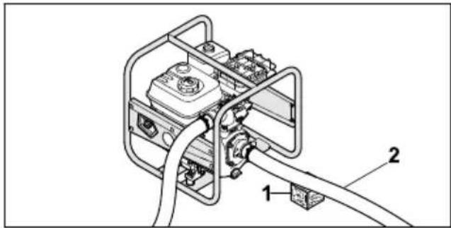
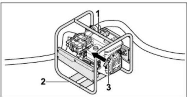
3 Overview
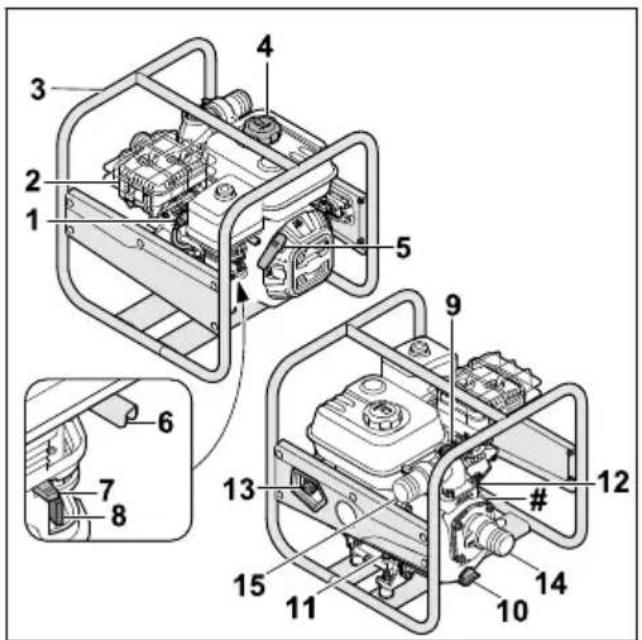
3.1 Water Pump
text_image
Technical diagram of a portable gas pump with numbered components and labeled parts1 Spark plug socket
The spark plug socket connects the ignition lead to the spark plug.
2 Muffler
The muffler reduces the water pump's noise level.
3 Frame
The frame is used to protect and transport the water pump.
4 Fuel tank cap
The fuel tank cap seals the fuel tank.
5 Starter handle
The starter handle is used to start the engine.
6 Throttle lever
The throttle lever is used to adjust the engine speed.
7 Choke lever
The choke lever is used for starting the engine.
8 Fuel cock
The fuel cock shuts off the fuel feed.
9 Screw plug
The screw plug seals the opening for adding water.
10 Screw plug
The screw plug seals the opening for draining water.
11 Front engine oil cap
The engine oil cap seals the opening for adding engine oil.
12 Rear engine oil cap
The engine oil cap seals the opening for checking the oil level.
13 Main switch
The main switch is used to switch on and stop the engine.
14 Suction opening
The suction opening is used to connect the suction hose.
15 Outlet opening
The outlet opening is used to connect the pressure hose.
# Rating plate with machine number
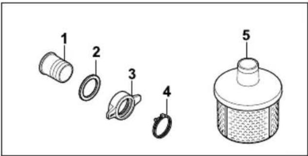
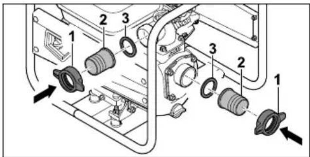
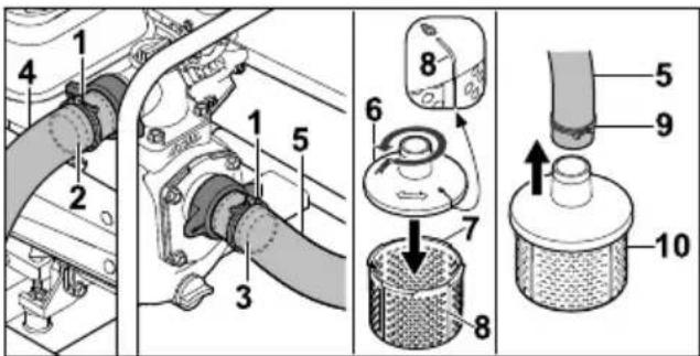
3.2 Components for Connecting the Hoses
text_image
Diagram showing exploded view of a mechanical component with numbered parts labeled 1 to 51 Connecting piece
The connecting piece is used to connect a hose.
2 Seal
The seal seals the connecting piece.
3 Union nut
The union nut secures the connecting piece to the water pump.
4 Clamp
The clamp secures a hose to the connecting piece.
5 Suction strainer
The suction strainer filters the water taken in.
3.3 Symbols
The symbols can be on the water pump, the engine or the oil filler neck and have the following meaning:

The fuel cock is opened and closed by moving the lever.

The choke lever must be activated when starting a cold engine.
4 Safety Precautions English
Note the engine oil capacity.

Read, understand and keep the instruction manual.
The engine must be filled with engine oil before starting.

This symbol indicates the throttle lever.
4 Safety Precautions
4.1 Warning Symbols
The warning symbols on the water pump have the following meaning:

Follow the safety instructions and their measures.

Read, understand and keep the instruction manual.

Wear hearing protection.
Do not breathe in exhaust fumes.
Do not touch hot surfaces.

Do not refuel when the engine is running or heated to a high temperature.
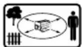
Maintain distance from objects and keep third parties away.
4.2 Intended Use
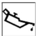
The STIHL WP 300.0 water pump is used for pumping fresh water to a maximum height of 33 m and from a maximum depth of 7 m. The water pump may only be used as a stand-alone unit.
The STIHL WP 300.0 water pump is not intended for the following applications:
- Pumping petrol, oil, thinner, solvent and similar materials
- Pumping acids, alkalis, bases and similar materials
– Pumping liquid food products - Pumping salt water
- Pumping water with a temperature above 40^ .
NOTICE
■ Local regulations and instructions govern the extraction of water from above-ground bodies of water.
▶ Observe and comply with local regulations.
WARNING
■ Failure to use the water pump as intended may result in serious or fatal injury to people and damage to property.
▶ Use the water pump as described in this instruction manual.
4.3 The Operator
WARNING
■ Users without adequate training or instruction cannot recognize or assess the risks involved in using the water pump. The user or other persons may sustain serious or fatal injuries.

▶ Read, understand and save the instruction manual.
▶ If the water pump is passed on to another person: Always give them the instruction manual.
▶ Make sure the user meets the following requirements:
- The user must be rested.
- The user must be in good physical condition and mental health to operate and work with the water pump. If the user's physical, sensory or mental ability is restricted, he or she may work only under the supervision of or as instructed by a responsible person.
- The user is able to recognize and assess the risks involved in using the water pump.
- The user must be of legal age or is being trained in a trade under supervision in accordance with national rules and regulations.
English 4 Safety Precautions
- The user has received instruction from a STIHL servicing dealer or other experienced user before working with the water pump for the first time.
- The user must not be under the influence of alcohol, medication or drugs.
▶ If you have any queries: Contact a STIHL servicing dealer for assistance.
- The water pump's ignition system produces an electromagnetic field. This field may interfere with some pacemakers. This can result in serious or fatal injuries.
▶ If the user has a pacemaker: Make sure the pacemaker is not affected.
4.4 Clothing and Equipment
WARNING
■ Long hair may be pulled into the water pump when working. This may result in serious injury to the user.
- Tie up long hair securely so that it is above the shoulders.
■ The user may come into contact with contaminated water or water may spray from the water pump or hoses when working. This may result in injury to the user.
▶ Wear close-fitting safety glasses. Suitable safety glasses are tested in accordance with EN 166 or national regulations and available commercially with the corresponding marking.
■ Noise is produced while working. Noise may damage the hearing.

▶ Wear hearing protection.
■ Unsuitable clothing may get caught in the water pump. This may result in serious injury to the user.
▶ Wear close-fitting clothing.
- Remove scarves and jewellery.
■ Wearing unsuitable footwear may cause the user to slip. This may result in injury to the user.
- Wear sturdy, closed-toed footwear with high-grip soles.
4.5 Work Area and Surroundings
WARNING
■ Bystanders, children and animals cannot recognize or assess the dangers of the water pump. Innocent bystanders, children and ani-
mals may be seriously injured and damage to property may occur.
- Keep bystanders, children and animals away from the work area.
▶ Do not leave the water pump unattended.
▶ Make sure that children cannot play with the water pump.
■ Hot exhaust gas is emitted through the muffler while the engine is running. Hot exhaust gas can ignite easily flammable materials and cause a fire.
- Keep exhaust gas well away from easily flammable materials.
4.6 Safe condition
The water pump is in a safe condition if the following points are observed:
– The water pump is not damaged.
– There is no fuel leaking from the water pump.
– The fuel tank cap is closed.
- The water pump is clean.
- The controls function properly and have not been modified.
- Hoses suitable for use with water pumps are fitted.
– The hoses are properly fitted.
- Only genuine STIHL accessories designed for this water pump model are fitted.
- The accessories are correctly attached.
WARNING
■ If not in safe condition, components may no longer operate correctly, safety devices may be disabled and fuel leakage may occur.
There is a risk of serious or fatal injury.
▶ Work only with an undamaged water pump.
▶ If fuel is leaking from the water pump: Do not use the water pump and contact a STIHL dealer for assistance.
▶ Close the fuel tank cap.
▶ If the water pump is dirty: Clean the water pump.
▶ Do not modify the water pump.
▶ If the controls do not function properly: Do not use your water pump.
▶ Only fit hoses that are suitable for use with water pumps.
▶ Only fit genuine STIHL accessories designed for this water pump model.
▶ Mount hoses and accessories as described in this instruction manual or the instructions supplied with the accessory.
- Never insert objects in the water pump's openings.
- Replace worn or damaged labels.
4 Safety Precautions English
▶ If you have any doubts, be sure to consult a STIHL dealer.
4.7 Fuel and Refuelling
WARNING
■ The fuel used for this water pump is petrol. Petrol is extremely inflammable. If petrol comes into contact with an open flame or hot objects, it may cause fires or explosions. This may result in serious or fatal injury to people and damage to property.
▶ Protect petrol from heat and fire.
▶ Do not spill petrol.
▶ If petrol is spilled: wipe up the petrol with a cloth and do not attempt to start the engine until all parts of the water pump and the area around the water pump are dry.
▶ Do not smoke.
- Do not refuel in the vicinity of flames.
▶ Before refuelling, stop the engine and allow it to cool.
▶ If the tank needs to be emptied: do this out of doors.
- Start the engine at least 3 m away from the refuelling site.
▶ Never store the water pump with petrol in the tank inside closed rooms.
■ Breathing in petrol fumes may result in poisoning.
▶ Do not breathe in petrol fumes.
▶ Refuel in a well-ventilated place.
■ The water pump warms up while working. The petrol expands and overpressure may occur in the fuel tank. Petrol may gush out when the fuel tank cap is opened. The gushing petrol may ignite. This may result in serious injury to the user.
- Allow the water pump to cool down before opening the fuel tank cap.
■ Clothing that comes into contact with petrol is highly inflammable. This may result in serious or fatal injury to people and damage to property.
▶ If clothing comes into contact with petrol: change clothing.
■ Petrol poses a risk to the environment.
▶ Do not spill fuel.
- Dispose of petrol in accordance with regulations and in an environmentally acceptable way.
■ If petrol comes into contact with the skin or eyes, this may cause irritation.
- Avoid contact with petrol.
▶ In the event of contact with the skin: wash the affected areas with plenty of soap and water.
In the event of contact with the eyes: rinse the eyes with plenty of water for at least 15 minutes and seek medical attention.
■ The water pump's ignition system generates sparks. Sparks may escape and cause fires and explosions in highly inflammable or explosive environments. This may result in serious or fatal injury to people and damage to property.
▶ Use the spark plugs described in this instruction manual.
▶ Screw in the spark plug and tighten firmly.
▶ Press on the spark plug socket firmly.
■ The water pump may be damaged if it is refu-elled with petrol that is not suitable for the engine.
▶ Use fresh, good-quality unleaded petrol.
▶ Observe the specifications in the engine instruction manual.
4.8 Working
WARNING
■ The user may lose control of the water pump if they do not start the engine correctly. This may result in serious injury to the user.
▶ Start the engine as described in this instruction manual.
■ If the water pump is operated without the hoses attached, the user's hands may get caught in the suction and outlet openings. This may result in serious injury to the user.
▶ Only operate the water pump with the hoses attached.
- Do not put your hands in the suction or outlet openings.
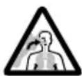
■ Exhaust fumes are produced when the engine is running. Breathing in exhaust fumes may result in poisoning.
▶ Do not breathe in exhaust fumes.
▶ Use the water pump in a well-ventilated place.
- Do not work in a well with the water pump.
▶ If nausea, headaches, vision problems, hearing problems or dizziness occur: stop working and consult a doctor.
■ If the user is wearing hearing protection and the engine is running, their perception and assessment of noise may be limited.
▶ Work calmly and carefully.
English 4 Safety Precautions
■ If the water pump changes or starts to behave differently when working, it may not be in safe condition. This may result in serious injury to people and damage to property.
- Stop working and consult a STIHL specialist dealer.
■ Water can freeze on the floor and in components of the water pump at temperatures below 0 °C. This may result in the user slipping, falling and becoming seriously injured. It may also result in damage to property.
- Do not use the water pump at temperatures below 0 °C.
■ If the suction hose or pressure hose is pulled, the water pump may move and fall over. This may result in damage to property.
- Do not pull on the suction hose or pressure hose.
■ If the water pump is placed on a sloping, uneven or unpaved surface, it may move and fall over. This may result in damage to property.
- Place the water pump on a horizontal, level and paved surface.
- Secure the water pump so it cannot move.
■ Taking in highly inflammable and explosive liquids may cause fires and explosions. This may result in serious or fatal injury to people and damage to property.
- Do not take in or discharge highly inflammable or explosive liquids.
■ Taking in irritating, corrosive and toxic liquids may endanger health and damage components of the water pump. This may result in serious or fatal injury to people and damage to property.
- Do not take in or discharge irritating, corrosive or toxic liquids.
■ The water pump is not sterile or food-safe. If liquid food products are taken in, they will be contaminated.
- Do not take in or discharge liquid food products.
■ If the water pump is not filled with water before starting the engine, this may result in damage to the water pump.
- Fill the water pump with water before starting the engine.
■ If the suction strainer is not attached, objects may be sucked into the water pump. The water pump may become clogged or damaged.
- Attach the suction strainer.
■ The engine of the water pump is not water-proof. If the water pump is placed in water, the engine may be damaged.
▶ Operate the water pump on a dry surface.
■ Badly routed hoses may become damaged and people may trip over them. This may result in injury to people and damage to the hoses.
- Route and mark the hoses so people cannot trip over them.
- Route the hoses so they are not stretched or tangled.
- Route the hoses so they do not become damaged, kinked or crushed or chafe.
- Protect the hoses from heat, oil and chemicals.
■ If people sit or stand on the water pump, they may come into contact with hot components and be seriously injured. If objects are placed on the water pump, they may fall down and cause serious injury to people.
▶ Do not sit or stand on the water pump.
- Do not place any objects on the water pump.
4.9 Transporting
WARNING
■ The water pump may tip over or move during transport. This may result in injury to people and damage to property.
▶ Stop the engine.
- Secure the water pump with lashing straps, belts or a net so it cannot tip over and move.
■ The muffler and engine may be hot after the engine has been running. This may result in the user burning themselves.
- Carry the water pump by the frame with the muffler pointing away from the body.
■ Water can freeze in components of the water pump at temperatures below 0 °C . This may result in damage to the water pump.
- Drain the water pump.
4.10 Storing
WARNING
■ Children are not aware of and cannot assess the dangers of a water pump and can be seriously injured.
▶ Shut off the engine.
- Store the water pump out of the reach of children.
■ Dampness can corrode the electrical contacts on the water pump and metal components.
This can damage the water pump.
- Store your water pump in a clean and dry condition.
5 Preparing the Water Pump for Operation English
■ Water can freeze in water pump components at temperatures below 0^ C. This can damage the water pump.
- Drain the water pump.
4.11 Cleaning, Maintenance and Repair
WARNING
■ The water pump may inadvertently start if the engine is running during cleaning, maintenance or repair. This may result in serious injury to people and damage to property.
▶ Stop the engine.
■ The muffler and engine may be hot after the engine has been running. This may result in people burning themselves.
- Wait until the muffler and engine have cooled down.
■ Abrasive cleaning agents or using a water jet or sharp objects for cleaning may result in damage to the water pump or hoses. If the water pump or hoses are not cleaned correctly, components may no longer operate correctly and safety devices may be disabled. This may result in serious injury to people.
- Clean the water pump as described in this instruction manual.
- Clean the hoses as described in this instruction manual.
■ If the water pump or hoses are not maintained or repaired as described in this instruction manual, components may no longer operate correctly and safety devices may be disabled. This may result in serious or fatal injury to people.
- Maintain or repair the water pump as described in this instruction manual.
- Maintain hoses as described in the instruction manual for the hoses used.
5 Preparing the Water Pump for Operation
5.1 Preparing the Water Pump for Operation
The following steps must be performed before commencing work:
-
Remove packaging material and transport locks.
▶ Make sure that the water pump is in safe condition, ☐4.6.
▶ Clean the water pump, 14.1. -
Connect the water pump to a water source, 6.1.
▶ Fill the water pump housing with water, C6.2.
▶ Refuel the water pump, 17.1.
▶ Add engine oil, 17.2.
▶ Check the controls, 19.1.
▶ If the steps cannot be performed: do not use the water pump and consult a STIHL specialist dealer.
6 Connecting to a water source
6.1 Connecting the Water Pump to a Water Source
The water pump can take in water from rain barrels, cisterns and from flowing or standing water.
natural_image
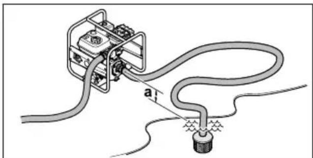
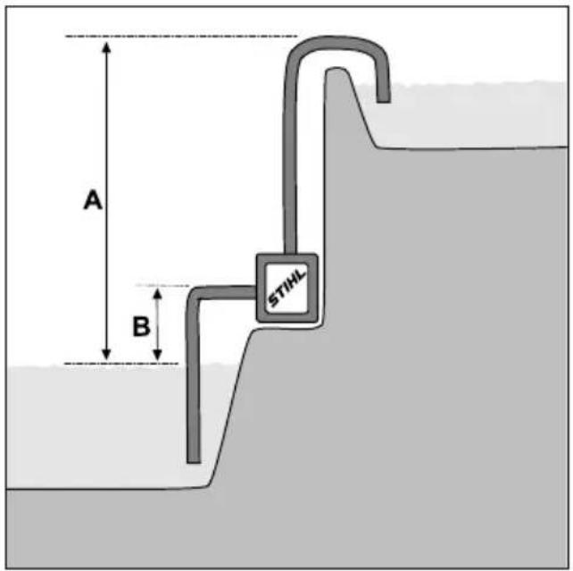
Diagram of a cable installation with a connector and wiring, no text or symbols presentIn order for the water to be taken in, the difference in height between the water pump and the water source must not exceed the maximum suction head (a), 18.1.
The suction hose must be inherently stable to prevent collapse in the event of negative pressure.
The suction strainer must be used.
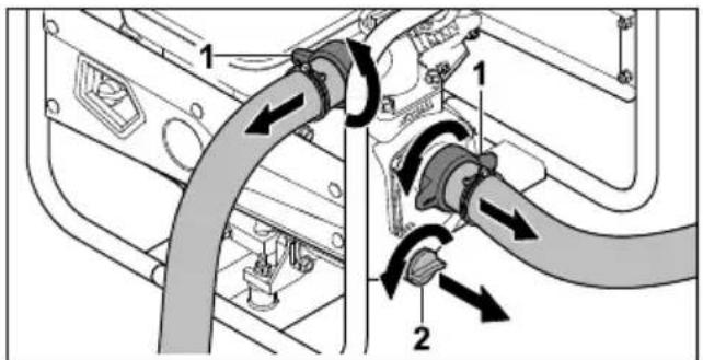
Attaching the hose connections
▶ Stop the engine.
text_image
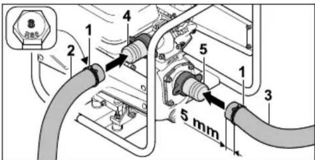
Technical diagram of a portable gas generator with labeled components and directional arrows indicating assembly or movement.▶ Screw on union nut (1) together with connecting piece (2) and seal (3). Do this at both openings.
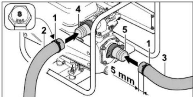
Attaching the hoses
text_image
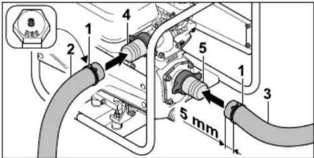
8 1 2 4 5 1 3 5 mm▶ Push clamps (1) onto pressure hose (2) and suction hose (3).
▶ Push pressure hose (2) over connecting piece (4).
- Push suction hose (3) over connecting piece (5).
text_image
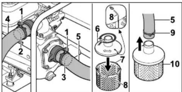
Technical diagram showing labeled parts of a mechanical device with numbered annotations- Align clamps (1) centrally over the resistance ribs of connecting pieces (2 and 3).
▶ Tighten the screws of clamps (1) firmly. Pressure hose (4) and suction hose (5) are firmly connected to the water pump.
▶ Place upper part of suction strainer (6) on lower part of suction strainer (7) and turn it anti-clockwise until markings (8) on upper part (6) and lower part (7) are in line. Upper part (6) and lower part (7) of the suction strainer are firmly connected to each other.
▶ Push clamp (9) onto the other end of suction hose (5).
▶ Push this end of suction hose (5) over the connecting piece of suction strainer (10). - Align clamp (9) centrally on the connecting piece of suction strainer (10).
▶ Tighten the screw of clamp (10) firmly. Suction strainer (10) is firmly connected to suction hose (5).
▶ Suspend suction strainer (10) in the water source so that it does not touch the bottom.

WARNING
■ Do not disconnect the water pump from the water source during operation and allow it to run empty.
Operating the water pump without the housing completely filled can cause severe damage to the pump.
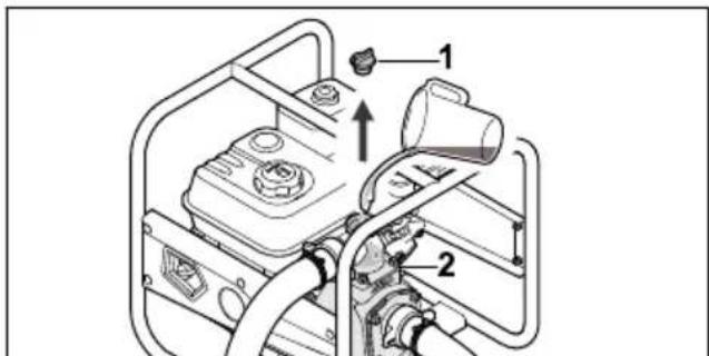
6.2 Filling the Water Pump Housing with Water
NOTICE
■ The water pump housing does not contain any water on delivery. In order for water to be taken in and pumped through the hoses, the water pump must be filled with water. Starting the engine with no or too little water in the water pump housing may damage the water pump.
▶ Add water to the water pump housing before starting the pump.
text_image
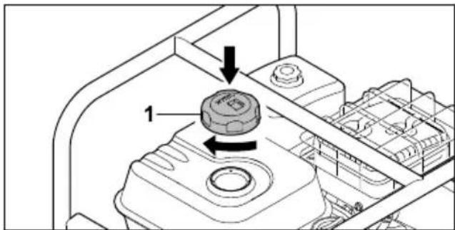
Technical diagram of a portable gas stove with labeled components and directional arrows indicating assembly or movement.▶ Turn screw plug (1) anti-clockwise until it can be removed.
▶ Fill the water pump housing with at least 2 litres of water.
▶ Replace screw plug (1).
▶ Turn screw plug (1) clockwise and tighten firmly by hand.
7 Refuelling the Water Pump and Adding Engine Oil
7.1 Refuelling the Water Pump
NOTICE
■ The water pump may be damaged if the correct fuel is not used.
▶ See the engine instruction manual.
▶ Stop the engine.
- Place the water pump on a flat surface with the fuel tank cap facing up.
8 Starting and Stopping the Engine English
- Clean the area around the fuel tank cap with a damp cloth.

text_image
Technical diagram showing a mechanical component with labeled parts and directional arrows indicating movement or assembly.▶ Turn fuel tank cap (1) anti-clockwise until it can be removed.
▶ Remove fuel tank cap (1).
- Add fuel without spilling any and stop at least 15 mm short of the fuel tank brim.

text_image
Technical diagram showing a mechanical component with labeled parts and directional arrows indicating assembly or movement.- Place fuel tank cap (1) on the fuel tank.
▶ Turn fuel tank cap (1) clockwise and tighten firmly by hand.
The fuel tank is sealed.
7.2 Adding Engine Oil
The engine oil lubricates and cools the engine.
The engine oil specification and capacity can be found in the engine instruction manual.
NOTICE
■ The water pump does not contain any engine oil on delivery. Starting the engine with no or too little engine oil may damage the water pump.
▶ Always check the engine oil level before starting and if necessary top up.
- Add the engine oil as described in the engine instruction manual.
8 Starting and Stopping the Engine
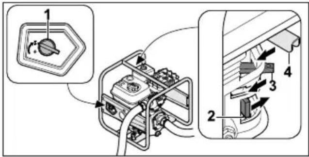
8.1 Starting the Engine
- Place the water pump on a level surface.
text_image
Technical diagram showing a mechanical switch assembly with labeled parts 1, 2, 3, and 4, including a circular component inset.▶ Turn main switch (1) to
▶ Push fuel cock (2) in the direction of the arrow.
▶ Push choke lever (3) in the direction of the arrow.
▶ Push throttle lever (4) in the direction of the arrow.

text_image
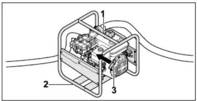
Technical diagram of an electrical device with labeled components and wiring connections▶ Press the water pump to the ground with the left hand on upper frame (1) and place the right foot on lower frame (2).
▶ Slowly pull out starter handle (3) with the right hand to the point of noticeable resistance.
- Keep quickly pulling out and returning starter handle (3) until the engine is running.
▶ Push the choke lever back so the engine does not stall.
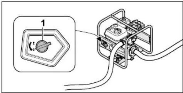
8.2 Stopping the Engine
text_image
Diagram showing a switch device connected to an electrical terminal with wiring, labeled with component number 1 and angle θ.▶ Turn main switch (1) to 0. The engine stops.
9 Checking the Water Pump
9.1 Checking the Controls
▶ Start the engine.
▶ Turn the main switch to 0. The engine stops.
English 10 Using the Water Pump
▶ If the engine does not cut out:
- Close the fuel cock and do not use the water pump; consult a STIHL dealer. The main switch is defective.
10 Using the Water Pump
10.1 Securing the Water Pump
- Secure the water pump so it cannot move.
10.2 Routing the Suction Hose
To prevent excessive strain on the threaded connection of the suction opening and to prevent the seal from being crushed or moved, place a suitable object under the suction hose.
natural_image
Technical diagram of a device with labeled components, showing internal wiring and connectors (no text or symbols present)- Place a suitable object (1) under suction hose (2) so that it runs as straight as possible and has no kinks.
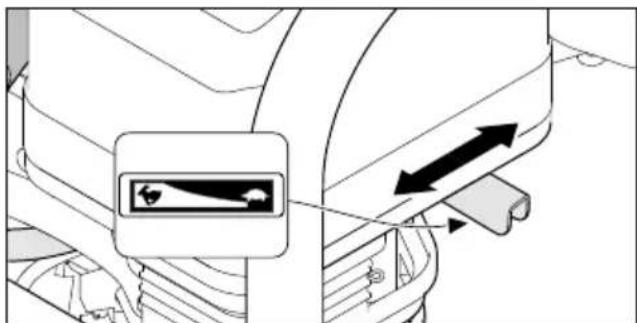
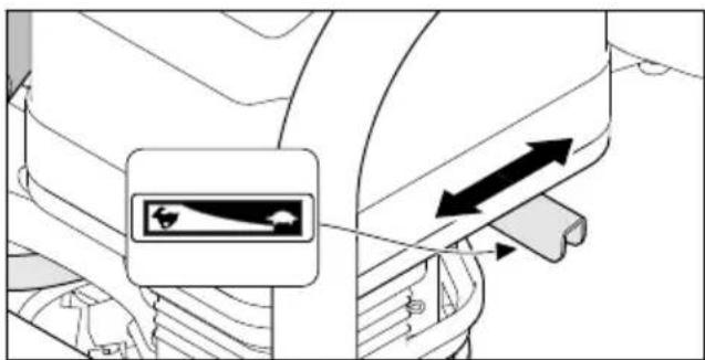
10.3 Operating the Pump
text_image
Diagram showing vehicle seatbelt mechanism with directional arrows and a warning symbolThe pump delivery rate can be adjusted by moving the throttle lever.
▶ Move the throttle lever to position ⬇: the pump delivery rate decreases.
▶ Move the throttle lever to position ◀ the pump delivery rate increases.
11 After Finishing Work
11.1 After Finishing Work
- Connect the water pump to a water source in such a way that no sand or dirt can be taken in.
▶ Start the engine. Sand and dirt are flushed out of the water pump and hoses.
▶ Stop the engine.
▶ Allow the water pump to cool down.

text_image
Diagram of a vehicle interior showing labeled parts with directional arrows indicating movement or flow.▶ Unscrew union nuts (1).
The hoses are detached.
▶ Turn screw plug (2) anti-clockwise until it can be removed.
Water flows out of the water pump.
▶ Tilt the water pump forwards to drain it completely.
▶ Replace screw plug (2).
▶ Turn screw plug (2) clockwise and tighten firmly by hand.
▶ If the water pump is wet: allow the water pump to dry.
▶ Clean the water pump.
12 Transporting
12.1 Transporting the Water Pump
▶ Stop the engine.
Carrying the water pump
- Carry the water pump by the frame with the muffler pointing away from the body.
Transporting the water pump in a vehicle
- Secure the water pump in an upright position so it cannot tip over or move.
13 Storing
13.1 Storing the Water Pump
▶ Stop the engine.
- Store the water pump in accordance with the following conditions:
- The water pump is out of reach of children.
- The water pump is clean and dry.
- The storage temperature is -20 °C to +60 °C.
▶ If the water pump is to be stored for more than 30 days:
▶ Open the fuel tank cap.
- Drain the fuel tank.
▶ Seal the fuel tank.
14 Cleaning
14.1 Cleaning the Water Pump
▶ Shut off the engine.
▶ Allow water pump to cool down.
- Clean the water pump with a damp cloth or STIHL resin solvent.
- Clean cooling air slots with a soft brush.
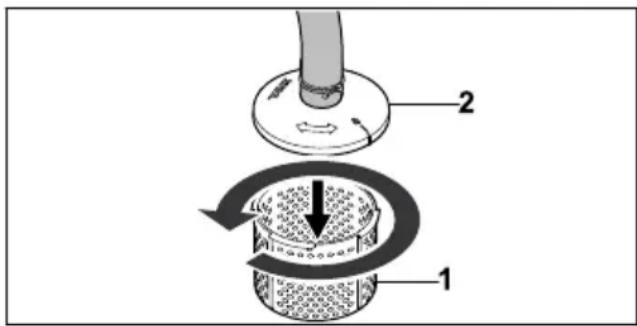
14.2 Cleaning the Suction Strainer
▶ Stop the engine.
- Rinse the suction strainer under running water.
text_image
Diagram illustrating a mechanical or fluidic device with labeled parts 1 and 2, showing directional flow and component placement.- For coarser soiling, detach lower part of suction strainer (1) from upper part of suction strainer (2) by turning it anti-clockwise and remove. Rinse the inside of the suction strainer under running water.
14.3 Cleaning the Hoses
▶ Shut off the engine.
▶ Clean the hoses with a damp cloth.
▶ Rinse the hoses with water.
15 Maintenance
15.1 Maintenance Intervals
Maintenance intervals are dependent on the ambient conditions and the working conditions. STIHL recommends the following maintenance intervals:
Engine
- Maintain the engine as described in the engine instruction manual.
Water pump
▶ Have the water pump inspected annually by a STIHL specialist dealer.
16 Repairing
16.1 Repairing the Water Pump
The water pump cannot be repaired by the user.
▶ If the water pump is damaged: Do not use your water pump and contact your STIHL servicing dealer for assistance.
17 Troubleshooting
17.1 Remedying Water Pump Faults
| Fault Cause Remedy | ||
| Engine cannot be started. | Insufficient fuel in fuel tank. | ▸ Refuel water pump. |
| Carburettor overheating. | Allow water pump to cool down. | |
| Carburettor iced up. | ▸ Allow water pump to warm up. | |
| Main switch set to position 0. | ▸ Press main switch. | |
| Inferior, dirty or old fuel in tank. | ▸ Use fresh, good quality fuel (unleaded petrol).▸ Clean carburettor.▸ Clean fuel line. | |
| Spark plug socket is detached from spark plug or ignition lead is not properly fastened to socket. | ▸ Clean or replace spark plug.▸ Check connection between ignition lead and plug. | |
| Spark plug is dirty, damaged or electrode gap is incorrect. | ▸ Clean or replace spark plug.▸ Adjust electrode gap. | |
| Engine flooded. ▶ Remove spark plug and dry; set main switch to 0 and pull starter rope repeatedly with spark plug removed. | ||
| Air filter dirty. ▶ Clean or replace air filter. | ||
| Oil level in engine too low. | ▸ Add engine oil. | |
| Engine difficult to start or engine power deteriorating. | Water in fuel tank and carburettor or carburettor is blocked. | ► Empty fuel tank, clean fuel line and carburettor. |
| Fuel tank contaminated. | ► Clean fuel tank. | |
| Spark plug dirty. ► Clean or replace spark plug. | ||
| Incorrect fuel used. ► Check fuel. | ||
| Air filter dirty. ► Clean or replace air filter. | ||
| Engine overheating. C | Cooling ribs dirty. ► Clean cooling ribs. | |
| Engine running roughly. | Incorrect fuel used. ► Check fuel. | |
| Insufficient fuel in fuel tank. | ► Refuel water pump. | |
| Air filter dirty. ► Clean or replace air filter. | ||
| Engine stops during operation. | Oil level in engine is too low and oil pressure sensor stops engine. | ► Top up engine oil. |
| Insufficient fuel in fuel tank. | ► Refuel water pump. | |
| Heavy smoke formation. | Oil level in engine is too high. | ► Drain engine oil. |
| Air filter dirty. ► Clean or replace air filter. | ||
| Excessive vibration during operation. | Vibration dampers worn. | ► Replace vibration dampers. |
| Water pump not pumping water. | Suction strainer or hoses are clogged. | ► Clean suction strainer and hoses. |
| Insufficient water. ► Ensure that a sufficient amount of water is available. | ||
| No water in water pump. | ► Connect water pump to a water source. ► Fill water pump with water. | |
| Maximum delivery | head or maximum suction head has been exceeded. | ► Observe maximum delivery head or maximum suction head. 18.1 |
| Suction hose collapsed on itself. | ► Use an inherently stable suction hose. | |
| Suction hose leaking or not connected properly. | ► Check suction hose and connection. | |
18 Specifications
18.1 STIHL WP 300.0 Water Pump
- Displacement: 212 cc
– Power (P) to ISO 8893: 4.4 kW - On-load speed (n): 3600 rpm
– Maximum idling speed ( n_0 ): 3800 rpm
– Weight (m) with empty fuel tank: 26 kg
– Maximum fuel tank capacity: 3.6 l - Connecting piece diameter: 51 mm (2 inches)
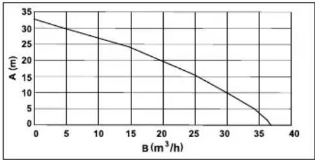
– Maximum delivery head: 33 m
– Maximum suction head: 7 m
text_image
A B STIHLA = Delivery head
B = Suction head
- Maximum delivery rate ( V_max ): 37 m³/h
The delivery rate depends on the delivery head:
line
| B (m³/h) | A (m) | |---|---| | 0 | 33 | | 5 | 30 | | 10 | 27 | | 15 | 24 | | 20 | 20 | | 25 | 16 | | 30 | 11 | | 35 | 4 | | 37 | 0 |A = Delivery head
B = Delivery rate
18.2 Sound Values
The K value for the sound pressure levels is 2 dB(A). The K value for the sound power levels is 2.4 dB(A).
- Sound pressure level L_pA measured in accordance with ISO 20361: 86 dB(A)
- Sound power level L_wA measured in accordance with 2000/14/EC: 99.0 dB(A)
- Sound power level L_wA guaranteed in accordance with 2000/14/EC: 101 dB(A)
18.3 Exhaust Emissions
The CO_2 value measured in the EU type approval procedure is specified at www.stihl.com/co2 in the product-specific technical data.
The measured CO_2 value was determined on a representative engine in accordance with a standardised test procedure under laboratory conditions and does not represent either an explicit or implied guarantee of the performance of a specific engine.
The applicable exhaust emission requirements are fulfilled by the intended usage and maintenance described in this instruction manual. The type approval expires if the engine is modified in any way.
18.4 REACH
REACH is an EC regulation and stands for the Registration, Evaluation, Authorisation and Restriction of Chemical substances.
For information on compliance with the REACH regulation see www.stihl.com/reach.
19 Spare Parts and Accessories
19.1 Spare parts and accessories
STIHL These symbols indicate original STIHL spare parts and original STIHL accessories.
STIHL recommends the use of original STIHL spare parts and accessories.
Despite ongoing market observation, STIHL is unable to judge the reliability, safety and suitability of other manufacturers' spare parts and accessories; accordingly, STIHL cannot warrant for the use of those parts.
Original STIHL spare parts and original STIHL accessories are available from STIHL dealers.
20 Disposal
20.1 Disposing of the Water Pump
Information on disposal is available from your local authority or from a STIHL dealer.
Improper disposal may be harmful to health and pollute the environment.
▶ Take STIHL products including packaging to a suitable collection point for recycling in accordance with local regulations.
- Do not dispose of the product with domestic waste.
21 EC Declaration of Conformity
21.1 STIHL WP 300.0 Water Pump
STIHL Tirol GmbH
Hans Peter Stihl-Strasse 5
6336 Langkampfen
Austria
declares under our sole responsibility that
- design: water pump
– nominal output: 4.4 kW - manufacturer's brand: STIHL
- type: WP 300.0
- serial number: VB03
complies with the relevant provisions of Directives 2000/14/EU, 2006/42/EC, 2011/65/EU and 2014/30/EU and has been developed and manufactured in accordance with the versions of the following standards valid on the date of manufacture: EN 809 and EN 55012.
The measured and guaranteed sound power levels were determined in accordance with Directive 2000/14/EC, Appendix V.
– Measured sound power level: 99.0 dB(A)
– Guaranteed sound power level: 101 dB(A)
The technical documents are stored at STIHL Tirol GmbH.
The year of manufacture and machine number are indicated on the water pump.
Langkampfen, 08.10.2021
STIHL Tirol GmbH
p.p. M. Thicla
Matthias Fleischer, Head of Research and Development Division
p.p. finnermann pm
Sven Zimmermann, Head of Quality Department
22 UKCA Declaration of Conformity
22.1 STIHL WP 300.0 Water Pump
STIHL Tirol GmbH
Hans Peter Stihl-Strasse 5
6336 Langkampfen
Austria
declares under our sole responsibility that
- design: water pump
– nominal output: 4.4 kW
– manufacturer's brand: STIHL - type: WP 300.0
– serial number: VB03
complies with the relevant provisions of the UK regulations Noise Emission in the Environment by Equipment for use Outdoors Regulations 2001, Supply of Machinery (Safety) Regulations 2008, Electromagnetic Compatibility Regulations 2016 and The Restriction of the Use of Certain Hazardous Substances in Electrical and Electronic Equipment Regulations 2012 and has been developed and manufactured in accordance with the versions of the following standards valid on the date of manufacture: EN 809 and EN 55012.
The measured and guaranteed sound power levels were determined in accordance with the UK regulation Noise Emission in the Environment by Equipment for use Outdoors Regulations 2001, Schedule 8.
– Measured sound power level: 99.0 dB(A)
– Guaranteed sound power level: 101 dB(A)
The technical documents are stored at STIHL Tirol GmbH.
The year of manufacture and machine number are indicated on the water pump.
Langkampfen, 01.07.2022
STIHL Tirol GmbH
p.p.
M. Thicka
Matthias Fleischer, Head of Research and Development Division
p.p.
fimmemann fm
Sven Zimmermann, Head of Quality Department
Table des matières
2.1 Documents applicables
text_image
Technical diagram of a portable gas pump system with numbered components and labeled partstext_image
Diagram showing exploded view of a mechanical component with numbered parts labeled 1 to 51 Tubulure
natural_image
Diagram of a cable installation with a connector and wiring, no text or symbols presenttext_image
Technical diagram of a mechanical device with numbered components and directional arrows indicating assembly or movement.text_image
Technical diagram showing labeled parts of a mechanical device with numbered components and directional arrows indicating assembly or operation.text_image
Technical diagram of a vehicle engine compartment with labeled parts and directional arrows indicating flow or movement.text_image
Technical diagram showing a mechanical component with labeled parts and directional arrows indicating movement or assembly.text_image
Technical diagram showing a mechanical component with labeled parts and directional arrows indicating assembly or movement.text_image
Technical diagram showing a mechanical switch assembly with labeled components and directional arrows indicating motion.text_image
Technical diagram of an electrical device with labeled components and wiring connectionstext_image
Diagram showing a device with labeled components and a magnified inset highlighting a circular component with '1' and '2'.natural_image
Technical diagram of a portable device with labeled components (no text or symbols present)text_image
Diagram showing vehicle seatbelt switch mechanism with directional arrows and a highlighted componenttext_image
Diagram showing mechanical assembly with labeled parts and directional arrows indicating motion or flowtext_image
Diagram illustrating a mechanical or fluidic device with labeled parts 1 and 2, showing directional flow and component movement.text_image
fimmervann ptext_image
Technical diagram of a portable gas pump system with numbered components and labeled parts1 Pipa de bujía
13 Interruptor principal
text_image
Diagram showing five labeled parts of a mechanical component, including threaded and ring components with numbered labels.1 Tubuladura
La tubuladura sirve para conectar una man- guera.
2 Junta
natural_image
Diagram of a cable installation with a connector and wiring, no text or symbols presenttext_image
Technical diagram of a portable gas generator with labeled components and directional arrows indicating assembly or movement.text_image
Technical diagram showing mechanical assembly with numbered components and labeled partstext_image
Technical diagram of a gas generator or pump system with labeled components and directional arrows indicating flow or movement.text_image
Technical diagram showing a mechanical component with labeled parts and directional arrows indicating movement or assembly.text_image
Technical diagram showing a mechanical component with labeled parts and directional arrows indicating assembly or movement.text_image
Technical diagram showing a switch mechanism with labeled components and directional arrows indicating assembly or operation.text_image
Technical diagram of an electrical device with labeled components and wiring connectionstext_image
Diagram showing a device with labeled components and wiring, including a circular component labeled '1' and a connector box.natural_image
Technical diagram of an electrical outlet with labeled components (no text or symbols present)text_image
Diagram showing vehicle seatbelt mechanism with directional arrows and a highlighted section viewtext_image
Diagram of a vehicle rear panel showing labeled components and directional arrows indicating flow or movement.text_image
Diagram illustrating a mechanical or fluidic device with labeled parts 1 and 2, showing internal components and directional flow.text_image
Technical diagram of a portable electrical device with numbered components and labeled partstext_image
Diagram showing five labeled parts of a mechanical component, including a cylindrical housing and a circular component with textured fill.1 Grlo
natural_image
Diagram of a cable installation with a connector and wiring, no text or symbols presentKako bi se voda mogla usisati, visinska razlika između pumpe za vodu i izvora vode ne smije biti veća od maksimalne visine usisavanja (a), 📄 18.1.
text_image
Technical diagram of a device with numbered components and directional arrows indicating assembly or movement.Zavijte zakretne priključke (1) zajedno s grlima (2) i brtvom (3).
Montiranje crijeva
text_image
8 1 2 4 5 1 3 5 mmtext_image
Technical diagram showing mechanical assembly with numbered components and labeled parts▶ Poravnajte zatezne obujmice (1) u sredini preko otpornih rebara grla (2 i 3).
- Čvrsto zategnite vijke zateznih obujmica (1). Tlačno crijevo (4) i usisno crijevo (5) čvrsto su spojeni na pumpu za vodu.
- Nasadite gornji dio cjedila (6) na donji dio cje-dila (7) i okrenite ga u smjeru suprotnom od kazaljke na satu dok oznake (8) na gornjem dijelu (6) i donjem dijelu (7) ne budu u istoj liniji.
Gornji dio (6) i donji dio (7) cjedila međusobno su čvrsto spojeni.
▶ Gurnite zateznu obujmicu (9) na drugi kraj usisnog crijeva (5)
- Drugi kraj usisnog crijeva (5) gurnite preko grla cjedila (10).
▶ Poravnajte zateznu obujmicu (9) u sredini na grlu cjedila (10).
- Čvrsto zategnite vijak zatezne obujmice (10). Cjedilo (10) je čvrsto spojeno na usisno crijevo (5).
Zakačite cjedilo (10) u izvor vode tako da cje-dilo (10) ne dodiruje tlo.

UPOZORENJE
text_image
Technical diagram of a portable gas generator with labeled components and directional arrows indicating flow or movement.Zaporni vijak (1) okrećite u smjeru suprotnom od kazaljke na satu dok zaporni vijak (1) ne uspijete ukloniti.
▶ Napunite kućište pumpe za vodu s najmanje 2 litre vode.
▶ Nasadite zaporni vijak (1).
Zaporni vijak (1) okrenite u smjeru kazaljke na satu i čvrsto ga zategnite rukom.
7 Punjenje pumpe za vodu gorivom i ulijevanje motor-nog ulja
text_image
Technical diagram showing a mechanical component with labeled parts and directional arrows indicating movement or assembly.- Čep spremnika goriva (1) okrećite u smjeru suprotnom od kazaljke na satu dok se čep spremnika goriva ne bude mogao skinuti.
▶ Skinite čep spremnika za gorivo (1).
▶ Gorivo ulijte tako da se ne prolije i do najviše 15 mm od ruba spremnika goriva.
text_image
Technical diagram showing a mechanical component with labeled parts and directional arrows indicating assembly or movement.- Čep spremnika goriva (1) postavite na spremnik goriva.
- Čep spremnika goriva (1) okrećite u smjeru kazaljke na satu i čvrsto ga zategnite rukom. Spremnik goriva je zatvoren.
7.2 Ulijevanje motornog ulja
Motorno ulje podmazuje i hladi motor.
Specifikacije o motornom ulju i količini punjenja možete naći u Uputama za uporabu motora.
UPUTA
■ U stanju pri isporuci motorno ulje nije uliveno. Ako se motor pokrene bez motornog ulja ili s vrlo malom količinom motornog ulja, pumpa za vodu može se oštetiti.
- Prije svakog postupka pokretanja provjeriti razinu motornog ulja i po potrebi dolijte motorno ulje.
▶ Motorno ulje ulijte u skladu s ovim Uputama za uporabu motora.
8 Pokretati/startati i zaustaviti motor
8.1 Pokretanje motora
text_image
Technical diagram showing a mechanical switch assembly with labeled parts and directional arrows indicating rotation or movement.▶ Okrenite glavnu sklopku (1) na
▶ Gurnite pipac za gorivo (2) u smjeru strelice.
▶ Gurnite polugu zaklopke pokretača (3) u smjeru strelice.
▶ Gurnite ručicu gasa (4) u smjeru strelice.
text_image
Technical diagram of a mechanical device with labeled components 1, 2, and 3▶ Lijevom rukom pritisnite pumpu za vodu na gornjem okviru (1) uz tlo, a desnom nogom stanite na donji okvir (2).
Polako desnom rukom izvucite ručicu za pokretanje (3) do pojave otpora.
- Brzo izvlačite i vraćajte ručicu za pokretanje (3) dok motor radi.
Polugu zaklopke pokretača gurnite unatrag kako biste spriječili preplavljivanje motora.
text_image
Diagram showing a device with a rotary knob and connected cables, labeled with number 1 in an inset view.- Okrenite glavnu skloplku (1) na 0. Motor se isključuje.
natural_image
Technical diagram of an electrical connector with labeled parts (1 and 2), showing internal components and wiring (no text or symbols beyond labels)▶ Stavite odgovarajući predmet (1) ispod usis-nog crijeva (2) tako da prolazi što ravnije i da se ne savija.
10.3 Pumpanje
text_image
Diagram showing vehicle door valve mechanism with directional arrows and a highlighted componentSnaga pumpanja može se podesiti s pomoću ručice gasa.
▶ Ručicu gasa gurnite u položaj : Snaga pumpanja se smanjuje.
▶ Ručicu gasa gurnite u položaj ♦ Snaga pumpanja se povećava.
11 Nakon rada
11.1 Nakon rada
- Priključite pumpu za vodu na izvor vode na takav način da se pijesak i prljavština ne mogu usisati.
hrvatski 12 Transport
▶ Pokretanje motora.
Pijesak i prljavština ispiru se iz pumpe za vodu i crijeva.
▶ Isključite motor.
▶ Ostavite pumpu za vodu da se ohladi.
text_image
Diagram of a vehicle rear panel showing pipe connections and valve parts with numbered labelstext_image
Diagram illustrating a mechanical or fluidic device with labeled components 1 and 2, showing a rotating component and flow direction.▶ U slučaju velike zaprljanosti, otpustite i uklonite donji dio cjedila (1) od gornjeg dijela cje-dila (2) okretanjem suprotno od kazaljke na satu i isperite iznutra tekućom vodom.
text_image
Technical diagram of a portable gas pump with numbered components and labeled partstext_image
Diagram showing five labeled parts of a mechanical component, including a cylindrical component and a perforated cylindrical body.natural_image
Diagram of a cable installation with a connector and wiring, no text or symbols presenttext_image
Technical diagram of a portable gas generator with labeled components and directional arrows indicating assembly or movement.text_image
Technical diagram showing mechanical assembly with numbered components and labeled partstext_image
Technical diagram of a portable gas generator with labeled components and directional arrow indicating flow or movement.text_image
Technical diagram showing a mechanical component with labeled parts and directional arrows indicating motion or assembly.text_image
Technical diagram showing a mechanical component with labeled parts and directional arrows indicating movement or assembly.text_image
Technical diagram showing a device with labeled components and directional arrows indicating motion or flow.text_image
Technical diagram of an electrical device with labeled components 1, 2, and 3text_image
Diagram showing a device with labeled components and wiring, including a magnified inset of the main component.natural_image
Technical diagram of an electrical device with labeled components (no text or symbols present)text_image
Diagram showing vehicle seatbelt mechanism with directional arrows and a highlighted componenttext_image
Diagram of a vehicle rear panel showing cable routing and valve positions with numbered annotationstext_image
Diagram illustrating a mechanical or fluidic device with labeled parts 1 and 2, showing a rotating component and flow direction.text_image
Technical diagram of a portable electrical enclosure with numbered components and labeled partstext_image
Diagram showing five labeled parts of a mechanical component, including threaded and ring components with numbered labels.1 Hrdlo
natural_image
Diagram of a cable installation with a connector and a spray nozzle, no text or symbols presenttext_image
Technical diagram of a portable gas generator with labeled components and directional arrows indicating assembly or movement.text_image
Technical diagram showing mechanical assembly with numbered components and labeled partstext_image
Technical diagram of a portable gas generator with labeled components and directional arrows indicating flow or movement.text_image
Technical diagram of a mechanical component with labeled parts and directional arrows indicating assembly or movement.text_image
Technical diagram showing a mechanical component with labeled parts and directional arrows indicating assembly or movement.text_image
Diagram showing electrical switch components with numbered parts and directional arrows indicating rotation or adjustment.text_image
Technical diagram of an electrical device with labeled components and wiring connectionstext_image
Diagram showing a device with a switch and labeled component, including a magnified inset view.natural_image
Technical diagram of an electrical connector with labeled parts (1 and 2), showing internal components and wiring (no text or symbols beyond labels)text_image
Diagram showing vehicle seatbelt mechanism with directional arrows and a warning symboltext_image
Diagram of a vehicle interior showing labeled parts and directional arrows indicating flow or movement.text_image
Diagram illustrating a mechanical or fluidic device with labeled components 1 and 2, showing internal flow and movement arrows.text_image
Technical diagram of a portable electrical device with numbered components and labeled parts1 Gyertyapipa
text_image
Diagram showing five labeled parts of a mechanical component, including threaded and ring components with numbered labels.1 Csöcsonk
natural_image
Diagram of a cable installation with a connector and grounding point, no text or symbols presenttext_image
Technical diagram of a portable air conditioner unit with labeled components and directional arrows indicating assembly or movement.text_image
Technical diagram showing mechanical assembly with numbered components and labeled partstext_image
Technical diagram of a portable gas generator with labeled components and directional arrows indicating flow or movement.natural_image
Technical diagram of a mechanical assembly with labeled component 1 (no text or symbols beyond label)text_image
Technical diagram showing a mechanical component with labeled parts and directional arrows indicating assembly or movement.text_image
Technical diagram showing a device with labeled components and directional arrows indicating rotation or movement.text_image
Technical diagram of a mechanical device with labeled components and wiring connectionstext_image
Diagram showing a device with a rotary knob and connected cable, labeled with number 1 and symbol 'z'.natural_image
Technical diagram of an electrical connector with labeled parts (1 and 2), showing internal components and wiring (no text or symbols beyond labels)text_image
Diagram showing vehicle safety warning sign with directional arrows and a warning symboltext_image
Diagram of a vehicle rear panel showing labeled components and directional arrows indicating flow or movement.text_image
Diagram illustrating a mechanical assembly with labeled parts 1 and 2, showing a rotating component with directional arrows.text_image
Technical diagram of a portable gas pump system with numbered components and labeled parts13 Interruptor principal
text_image
Diagram showing five labeled parts of a mechanical component, including threaded and flanged parts with a central cylindrical housing.1 Bocal
natural_image
Diagram of a cable installation with a connector and wiring, no text or symbols presenttext_image
Technical diagram of a portable gas generator with labeled components and directional arrows indicating assembly or movement.text_image
Technical diagram showing mechanical assembly with numbered components and labeled partstext_image
Technical diagram of a vehicle engine compartment with labeled parts 1 and 2, showing structural components and directional arrows.natural_image
Technical diagram of a mechanical assembly with labeled component 1 (no text or symbols beyond label)text_image
Technical diagram showing a mechanical component with labeled parts and directional arrows indicating assembly or movement.text_image
Technical diagram showing a switch mechanism with labeled parts 1, 2, 3, and 4, including a magnified inset view.text_image
Technical diagram of an electrical device with labeled components and wiring connectionstext_image
Diagram showing a device with labeled components and wiring, including a magnified inset of a circular component labeled '1'.natural_image
Technical diagram of a portable device with labeled components (no text or symbols present)text_image
Diagram showing vehicle seatbelt mechanism with directional arrows and a highlighted componenttext_image
Diagram of a vehicle rear panel showing labeled components and directional arrows indicating flow or movement.text_image
Diagram illustrating a mechanical or fluidic device with labeled parts 1 and 2, showing internal components and directional arrows.18.1 Bomba de água STIHL WP 300.0
21.1 Bomba de água STIHL WP 300.0
STIHL Tirol GmbH
22.1 Bomba de água STIHL WP 300.0
STIHL Tirol GmbH
text_image
Technical diagram of a portable electrical device with numbered components and labeled partstext_image
Diagram showing five labeled mechanical components with numbered parts, including a cylindrical component and a wash bottle.1 Hrdlo
Hrdlo slúži na pripojenie hadice.
2 Tesnenie
natural_image
Diagram of a cable installation with a connector and a plug, showing wiring connections (no text or symbols)text_image
Technical diagram of a portable air conditioner unit with numbered components and directional arrows indicating assembly or movement.▶ Naskrutkujte otočné matice (1) spolu s hrdlami (2) a tesnením (3).
Pripojenie hadíc
text_image
8 1 2 4 5 1 3 5 mm▶ Nasad'te upínacie objímky (1) na tlakovú hadicu (2) a saciu hadicu (3).
▶ Nasad'te tlakovú hadicu (2) na hrdlo (4).
▶ Nasad'te saciu hadicu (3) na hrdlo (5).
text_image
Technical diagram showing mechanical assembly with numbered components and labeled partstext_image
Technical diagram of a gas generator or pump system with labeled components and directional arrows indicating flow or movement.text_image
Technical diagram showing a mechanical component with labeled parts and directional arrows indicating motion or assembly.text_image
Technical diagram showing a mechanical component with labeled parts and directional arrows indicating assembly or movement.text_image
Technical diagram showing a switch mechanism with labeled parts 1, 2, 3, and 4, including a zoomed-in view of the switch.text_image
Technical diagram of a device with labeled components, showing internal wiring and component layouttext_image
Diagram showing a device with a rotary knob and connected tubing, labeled with number 1 in an inset view.▶ Otočte hlavný vypínač (1) na 0. Motor sa vypne.
natural_image
Technical diagram of an electrical device with labeled components (no text or symbols present)text_image
Diagram showing vehicle seatbelt mechanism with directional arrows and a highlighted componenttext_image
Diagram of a vehicle rear panel showing labeled components and directional arrows indicating flow or movement.text_image
Diagram illustrating a mechanical or fluidic device with labeled parts 1 and 2, showing a rotating component and directional arrows.text_image
Technical diagram of a portable electrical device with numbered components and labeled partstext_image
Diagram showing five labeled parts of a mechanical component, including threaded and flanged parts with numbered labels.1 Aansluitstuk
natural_image
Diagram of a cable installation with a connector and wiring, no text or symbols presenttext_image
Technical diagram of a portable gas generator with labeled components and directional arrows indicating assembly or movement.text_image
Technical diagram showing labeled parts of a mechanical device with numbered annotationstext_image
Technical diagram of a portable gas generator with labeled components and directional arrows indicating flow or movement.text_image
Technical diagram showing a mechanical component with labeled parts and directional arrows indicating motion or assembly.text_image
Technical diagram showing a mechanical component with labeled parts and directional arrows indicating assembly or movement.text_image
Technical diagram showing a mechanical device with labeled components and directional arrows indicating assembly or operation.text_image
Technical diagram of an electrical device with labeled components and wiring connectionstext_image
Diagram showing a switch device connected to a motor with wiring, labeled with component number 1 and rotation indicator.natural_image
Technical diagram of a device with labeled components, showing internal wiring and housing (no text or symbols present)text_image
Diagram showing vehicle seatbelt with directional arrows and a warning symbol for lifting a weighttext_image
Diagram of a vehicle interior showing labeled parts with directional arrows indicating flow or movement.text_image
Diagram illustrating a mechanical or fluidic device with labeled parts 1 and 2, showing directional flow and component movement.text_image
Technical diagram of a portable gas pump with numbered components and labeled partstext_image
Diagram showing five labeled parts of a mechanical component, including threaded and ring components with numbered labels.1 Штуцер
natural_image
Diagram of a cable installation with a connector and a sensor, no text or symbols presenttext_image
Technical diagram of a device with numbered components and directional arrows indicating assembly or movement.text_image
Technical diagram of a mechanical assembly with numbered components and labeled partstext_image
Technical diagram of a portable gas generator with labeled components and directional arrows indicating flow or movement.text_image
Technical diagram showing a mechanical component with labeled parts and directional arrows indicating motion or assembly.text_image
Technical diagram showing a mechanical component with labeled parts and directional arrows indicating movement or assembly.text_image
Technical diagram showing a switch mechanism with labeled components and directional arrows indicating assembly or operation.text_image
Technical diagram of a mechanical device with labeled components and wiring connectionstext_image
Diagram showing a switch device connected to an electrical box with wiring, labeled with component number 1.text_image
Diagram showing vehicle seatbelt mechanism with directional arrows and a labeled switch symboltext_image
Diagram showing cable routing or installation steps with numbered components and directional arrows indicating flow direction.text_image
Diagram illustrating a mechanical or fluidic device with labeled parts 1 and 2, showing a rotating component and directional arrows.text_image
Technical diagram of a portable electrical device with numbered components and labeled parts1 Konektor busi
text_image
Diagram showing five labeled parts of a mechanical component, including a cylindrical housing and a ring-like structure.1 Nozel
natural_image
Diagram of a cable installation with a connector and wiring, no text or symbols presenttext_image
Technical diagram of a portable gas generator with labeled components and directional arrows indicating assembly or movement.text_image
Technical diagram showing mechanical assembly with numbered components and labeled partstext_image
Technical diagram of a portable gas generator with labeled components and directional arrows indicating flow or movement.text_image
Technical diagram showing a mechanical component with labeled parts and directional arrows indicating movement or assembly.text_image
Technical diagram showing a mechanical component with labeled parts and directional arrows indicating movement or assembly.▶ Letakkan kembali tutup tangki bahan bakar (1) pada tangki bahan bakar.
▶ Putar tutup tangki bahan bakar (1) searah jarum jam dan kencangkan dengan tangan. Tangki bahan bakar tertutup.
7.2 Isi oli mesin
Oli mesin melumaskan sekaligus mendinginkan mesin.
text_image
Technical diagram showing a mechanical switch assembly with labeled parts 1, 2, 3, and 4, including a zoomed-in view of the switch.▶ Putar sakelar utama (1) ke arah
▶ Gunakan katup bahan bakar (2) ke arah sesuai anak panah.
▶ Gunakan tuas flap starter (3) ke arah sesuai anak panah.
▶ Gunakan tuas gas (4) ke arah sesuai anak panah.
text_image
Technical diagram of an electrical device with labeled components and wiring connectionstext_image
Diagram showing a device with a rotary knob and connected tubing, labeled with number 1 in an inset view.natural_image
Technical diagram of an electrical device with labeled components (no text or symbols present)text_image
Diagram showing vehicle seatbelt mechanism with directional arrows and a highlighted componenttext_image
Diagram showing cable routing with numbered components and directional arrows indicating flow or movementtext_image
Diagram illustrating a mechanical or fluidic device with labeled components 1 and 2, showing flow direction and movement.text_image
Technical diagram of a portable electrical device with numbered components and labeled parts1 Κάλυμμα μπουζί
text_image
Diagram showing five labeled parts of a mechanical component, including threaded and ring components with numbered labels.1 Στόμιο
natural_image
Diagram of a mechanical device with hoses and a central component, no text or symbols presenttext_image
Technical diagram of a portable gas generator with labeled components and directional arrows indicating assembly or movement.text_image
Technical diagram showing labeled mechanical components with numbered parts, likely illustrating a valve or pump assembly.text_image
Technical diagram of a portable gas generator with labeled components and directional arrows indicating flow or movement.natural_image
Mechanical assembly diagram showing a component with labeled parts and directional arrows (no text or symbols present)text_image
Technical diagram showing a mechanical component with labeled parts and directional arrows indicating assembly or movement.text_image
Technical diagram showing electrical switch connections with labeled parts 1, 2, 3, and 4text_image
Technical diagram of an electrical device with labeled components and wiring connectionstext_image
Diagram showing a device with labeled components and wiring, including a magnified inset of a circular component labeled '1'.natural_image
Technical diagram of an electrical connector with labeled parts (1 and 2), showing internal components and wiring (no text or symbols beyond labels)text_image
Diagram showing vehicle seatbelt mechanism with directional arrows and a magnified inset highlighting the left side of the seatbelt.text_image
Diagram of a device showing labeled components and directional arrows indicating flow or movementtext_image
Diagram illustrating a mechanical or fluidic device with labeled parts 1 and 2, showing internal components and directional flow.text_image
Technical diagram of a portable electrical device with numbered components and labeled partstext_image
Diagram showing five labeled parts of a mechanical component, including threaded and ring components with numbered labels.1 Chi tiết nối
natural_image
Diagram of a cable installation with a connector and tubing, no text or symbols presenttext_image
Technical diagram of a portable air conditioner unit with numbered components and directional arrows indicating assembly or movement.text_image
Technical diagram showing labeled parts of a mechanical device with numbered components and a close-up view of the component.text_image
Technical diagram of a vehicle engine compartment with labeled parts 1 and 2, showing structural components and directional arrows.text_image
Technical diagram showing a mechanical component with labeled parts and directional arrows indicating movement or assembly.text_image
Technical diagram showing a mechanical component with labeled parts and directional arrows indicating movement or assembly.text_image
Diagram showing electrical switch components with numbered parts and a magnified view of the switch knobtext_image
Technical diagram of a mechanical device with labeled components and wiring connectionstext_image
Technical diagram showing a device with labeled components and an inset view of a circular component with a pointer indicating '1'.natural_image
Technical diagram of an electrical device showing internal components and wiring (no text or labels)text_image
Diagram showing vehicle seatbelt mechanism with directional arrows and a highlighted componenttext_image
Diagram showing mechanical assembly with labeled parts and directional arrows indicating motion or flowtext_image
Diagram illustrating a mechanical or fluidic device with labeled components and directional arrows indicating motion or flow.Equipment for use Outdoors Regulations 2001, Supply of Machinery (Safety) Regulations 2008,
Electromagnetic Compatibility Regulations 2016
và The Restriction of the Use of Certain Hazardous Substances in Electrical and
text_image
Technical diagram of a mechanical device with numbered components and labeled partstext_image
Diagram showing five labeled parts of a mechanical component, including a cylindrical component and a cylindrical housing with a mesh cap.1 Króciec
natural_image
Diagram of a cable installation with a connector and a plug, showing wiring connections (no text or symbols)text_image
Technical diagram of a portable air conditioner unit with numbered components and directional arrows indicating assembly or movement.text_image
Technical diagram showing labeled parts of a mechanical device with numbered annotationstext_image
Technical diagram of a mechanical device with labeled parts 1 and 2, showing internal components and directional arrows.text_image
Technical diagram showing a mechanical component with labeled parts and directional arrows indicating movement or assembly.text_image
Technical diagram showing a mechanical component with labeled parts and directional arrows indicating movement or assembly.text_image
Technical diagram showing a device with labeled components and directional arrows indicating assembly or connection.text_image
Technical diagram of a mechanical device with labeled components and wiring connectionstext_image
Diagram showing a switch device connected to an electrical terminal with wiring, accompanied by a magnified view of the switch's internal structure.natural_image
Technical diagram of an electrical device with labeled components (no text or symbols present)text_image
Diagram showing vehicle seatbelt mechanism with directional arrows and a warning sign indicating left side of seatbelt.text_image
Diagram of a vehicle interior showing labeled components and directional arrows indicating flow or movement.12.1 Transport motopompy
▶ Wyłączyć silnik.
text_image
Diagram illustrating a mechanical or fluid system with labeled components 1 and 2, showing directional flow and circular movement.text_image
Technical diagram of a portable electrical device with numbered components and labeled partstext_image
Diagram showing five labeled parts of a mechanical component, including threaded and ring components.1 Накрайник
natural_image
Diagram of a cable installation with a connector and wiring, no text or symbols presenttext_image
Technical diagram of a portable gas generator with labeled components and directional arrows indicating assembly or movement.text_image
Technical diagram showing labeled parts of a mechanical assembly with numbered annotationstext_image
Technical diagram of a portable gas generator with labeled components and directional arrows indicating flow or movement.text_image
Technical diagram showing a mechanical component with labeled parts and directional arrows indicating assembly or movement.text_image
Technical diagram showing a mechanical component with labeled parts and directional arrows indicating movement or assembly.text_image
Technical diagram showing a device with labeled components and a circular inset showing a rotary knob.text_image
Technical diagram of a mechanical device with labeled parts 1, 2, and 3, showing internal components and wiring.text_image
Diagram showing a device with a rotary knob and connected cable, labeled with number 1 and symbol z.natural_image
Technical diagram of a device with labeled components, showing internal wiring and connectors (no text or symbols present)text_image
Diagram showing vehicle safety instructions with directional arrows and a highlighted componenttext_image
Diagram of a vehicle rear panel showing pipe connections and valve parts with numbered labelstext_image
Diagram illustrating a mechanical or fluidic device with labeled components and directional arrows indicating flow or movement.Equipment for use Outdoors Regulations 2001, Schedule 8.
text_image
Technical diagram of a portable electrical enclosure with numbered components and labeled parts1 Fişa de bujie
text_image
Diagram showing exploded view of a mechanical component with numbered parts labeled 1 to 51 Stut
natural_image
Diagram of a cable installation with a hose and base mount, no text or symbols presenttext_image
Technical diagram of a mechanical device with numbered components and directional arrows indicating assembly or movement.text_image
Technical diagram showing mechanical assembly with numbered components and labeled partstext_image
Technical diagram of a vehicle engine compartment with labeled parts 1 and 2, showing structural components and directional arrows.text_image
Technical diagram showing a mechanical component with labeled parts and directional arrows indicating movement or assembly.text_image
Technical diagram showing a mechanical component with labeled parts and directional arrows indicating assembly or movement.text_image
Technical diagram showing a device with labeled components and directional arrows indicating rotation or movement.text_image
Technical diagram of a mechanical device with labeled components 1, 2, and 3, showing internal components and wiring.text_image
Diagram showing a switch device with labeled component 1 and wiring, including a magnified inset view.natural_image
Technical diagram of an electrical device with labeled components (no text or symbols present)text_image
Diagram showing vehicle traffic flow with directional arrows and a highlighted component with a left-turn arrowtext_image
Diagram showing cable routing or installation with numbered components and directional arrows indicating flow pathstext_image
Diagram illustrating a mechanical or fluidic device with labeled parts 1 and 2, showing a rotating component with directional arrows.text_image
Technical diagram of a portable gas pump system with numbered components and labeled parts1 Utikač za svećice
text_image
Diagram showing five labeled parts of a mechanical component, including threaded and ring components with numbered labels.1 Priključak
natural_image
Diagram of a cable installation with a plug and tubing, no text or symbols presentDa bi voda bila usisana, razlika u visini između pumpe za vodu i izvora vode ne sme da premaši maksimalnu visinu usisavanja (a), 8.1.
Usisno crevo mora biti samo po sebi stabilno da bi se sprečio kolaps pod negativnim pritiskom.
Mora se koristiti usisna korpa.
text_image
Technical diagram of a mechanical device with numbered components and directional arrows indicating assembly or movement.text_image
Technical diagram showing mechanical assembly with numbered components and labeled parts▶ Poravnajte stezne obujmice (1) centralno preko rebara otpora priključaka (2 i 3).
- Čvrsto pritegnite zavrtnje steznih obujmica (1). Crevo za pritisak (4) i usisno crevo (5) čvrsto su povezani sa pumpom za vodu.
Gornji deo usisne korpe (6) postavite na donji deo usisne korpe (7) i čvrsto zavrnite okrećući ga suprotno od smera kretanja kazaljke na satu sve dok se oznaka (8) na gornjem delu (6) ne poklopi sa oznakom na donjem delu (7). Gornji deo (6) i donji deo (7) usisne korpe sada su čvrsto međusobno povezani.
▶ Steznu obujmicu (9) gurnite na drugi kraj usis-nog creva (5)
▶ Prevucite drugi kraj usisnog creva (5) preko priključka usisne korpe (10).
▶ Poravnajte steznu obujmicu (9) centralno na priključku usisne korpe (10).
- Čvrsto pritegnite zavrtanj stezne obujmice (10).
Usisna korpa (10) je čvrsto povezana sa usisnom crevom (5).
▶ Okačite usisnu korpu (10) u izvoru vode tako da usisna korpa (10) ne dodiruje tlo.

UPOZORENJE
text_image
Technical diagram of a portable gas generator with labeled components and directional arrows indicating flow or movement.- Okrećite navojni čep (1) suprotno od smera kretanja kazaljke na satu sve dok ne budete mogli da uklonite navojni čep (1).
▶ Napunite kućište pumpe za vodu sa najmanje 2 l vode.
▶ Pričvrstite navojni čep (1). - Okrećite navojni čep (1) u smeru kretanja kazaljke na satu i čvrsto ga pritegnite rukom.
7 Punjenje pumpe za vodu i dolivanje motornog ulja
7.1 Punjenje pumpe za vodu
UPUTSTVO
- Ako se u pumpu za vodu ne sipa odgovarajuće gorivo, pumpa za vodu može da se ošeteti. - Konsultujte uputstvo za upotrebu motora.
text_image
Technical diagram showing a mechanical component with labeled parts and directional arrows indicating assembly or movement.- Okrećite zatvarač rezervoara za gorivo (1) u smeru suprotnom od kretanja kazaljke na satu sve dok ne budete mogli da ga skinete.
▶ Skinite zatvarač rezervoara za gorivo (1).
▶ Sipajte gorivo tako da ne prospete nijednu kap i toliko da ostane barem 15 mm praznog prostora do vrha rezervoara za gorivo.
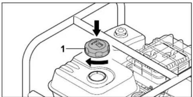
text_image
Technical diagram showing a mechanical component with labeled parts and directional arrows indicating assembly or movement.▶ Vratite zatvarač rezervoara za gorivo (1) na rezervoar za gorivo.
- Okrećite zatvarač rezervoara za gorivo (1) u smeru kretanja kazaljke na satu i zategnite ga rukom.
Rezervoar za gorivo je zatvoren.
text_image
Diagram showing electrical switch connections with labeled parts 1, 2, 3, and 4, including a rotary knob and wiring.text_image
Technical diagram of an electrical device with labeled components and wiring connections- Pritisnite pumpu za vodu na tlo tako što ćete je levom rukom držati za gornji okvir (1), a desnim stopalom pritiskati donji okvir (2).
▶ Desnom rukom polako povlačite ručku startera (3) sve dok ne osetite otpor. - Brzo izvlačite i vraćajte ručku startera (3) sve dok se motor ne pokrene.
- Polugu za pokretanje gurnite unazad da motor ne bi presisao.
text_image
Diagram showing a device with labeled components and a magnified inset showing a circular component with angular measurement.▶ Glavni prekidač (1) okrenite na 0. Motor će se isključiti.
9 Provera pumpe za vodu
9.1 Provera komandi
natural_image
Technical diagram of an electrical device with labeled components (no text or symbols present)▶ Postavite odgovarajući predmet (1) ispod usis-nog creva (2) tako da crevo stoji što je moguće ravnije i da nema pregiba.
10.3 Pumpanje
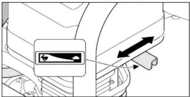
text_image
Diagram showing vehicle safety warning sign with directional arrows and a magnified inset of a vehicle's left side.text_image
Diagram of a vehicle interior showing labeled components and directional arrows indicating flow or movement.▶ Odvijte preklopnu navrtku (1). Creva su demontirana.
▶ Okrećite navojni čep (2) suprotno od smera kretanja kazaljke na satu sve dok ne budete mogli da uklonite navojni čep (2).
Voda ističe iz pumpe za vodu.
▶ Nagnite pumpu za vodu napred da biste je potpuno ispraznili.
▶ Postavite navojni čep (2).
- Okrećite navojni čep (2) u smeru kretanja kazaljke na satu i čvrsto ga pritegnite rukom.
- Ukoliko je pumpa za vodu vlažna: Dozvolite pumpi za vodu da se osuši.
▶ Očistite pumpu za vodu.
12 Transportovanje
12.1 Transport pumpe za vodu
▶ Isključite motor.
Nošenje pumpe za vodu
▶ Pumpu za vodu nosite držeći je za okvir i to tako da prigušivač zvuka bude okrenut od tela.
Transport pumpe za vodu vozilom
text_image
Diagram illustrating a mechanical or fluidic device with labeled parts 1 and 2, showing directional flow and component placement.▶ U slučaju veće količine prljavštine, odvojite donji deo usisne korpe (1) od gornjeg dela
17 Otklanjanje smetnji
17.1 Otklanjanje smetnji na pumpi za vodu
natural_image
Abstract black-and-white striped pattern with no text or symbols0478-701-9901-D