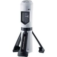
MultiCableChecker - Measuring equipment Laserliner - Free user manual and instructions
Find the device manual for free MultiCableChecker Laserliner in PDF.
| Product Type | Multi-use cable tester and locator |
| Brand | Laserliner |
| Model | MultiCableChecker |
| Category | Measuring equipment |
| Dimensions (L x H x D) | Transmitter: 49 x 127 x 34 mm; Receiver: 39 x 187 x 30 mm |
| Weight (battery included) | Transmitter: 130 g; Receiver: 135 g |
| Power supply | 1 9V battery (IEC LR6, alkaline) per unit |
| Main functions | Cable locating, continuity testing, LAN cabling check (RJ45), telephone and coaxial cable checking, conductor identification, LED flashlight, audio signal |
| Included connectors and adapters | RJ11, RJ45, BNC, TV coaxial (male and female), F adapter (male and female), test terminals with clips |
| Range in SCAN mode | Measurement depth from 0 to 5 cm |
| Maximum test length (continuity) | 3 km |
| Operating temperature | 0 °C to 40 °C |
| Operating humidity | 80 % RH max., non-condensing |
| Max. working altitude | 2000 m |
| Maintenance and cleaning | Clean with a slightly damp cloth; do not use solvents or abrasive products; remove batteries before prolonged storage; store in a dry and clean place |
| Safety | Do not measure live circuits; ensure absence of voltage before use; discharge capacitors; use only original adapters; do not open battery compartment when circuit is live; keep out of reach of children |
| Spare parts and repairability | Included accessories (adapters, cables, headset); no specific spare parts mentioned; contact Laserliner customer service |
| General information | Compliant with EMC directive 2014/30/EU and WEEE directive; warranty card and additional notes available at http://laserliner.com/info?an=mucache |
| Laser class (LED flashlight) | Risk group RG 0 (harmless to eyes and skin) |
Frequently Asked Questions - MultiCableChecker Laserliner
User questions about MultiCableChecker Laserliner
0 question about this device. Answer the ones you know or ask your own.
Ask a new question about this device
Download the instructions for your Measuring equipment in PDF format for free! Find your manual MultiCableChecker - Laserliner and take your electronic device back in hand. On this page are published all the documents necessary for the use of your device. MultiCableChecker by Laserliner.
USER MANUAL MultiCableChecker Laserliner
text_image
RJ11 RJ45 1 2 3 MODE STATUS SCAN SCAN MODE IAN MODE 7 8 STATUS IAN Laserliner® MultiCable-Checker TX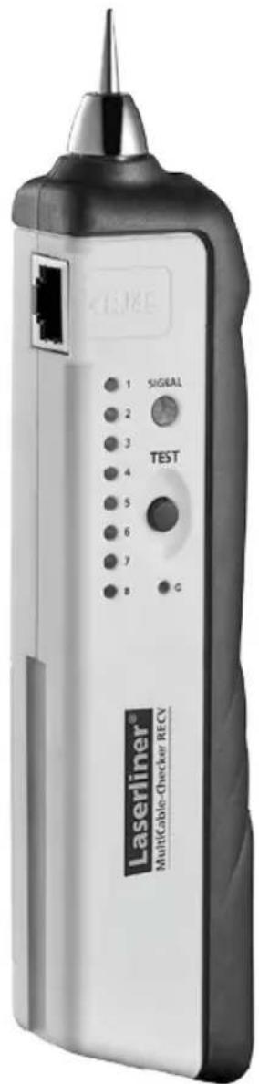
text_image
1 2 3 4 5 6 7 8 SIGNAL TEST G Laserliner® Multicable-Checker RECV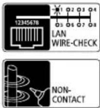
text_image
12345678 LAN WIRE-CHECK NON- CONTACT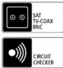
text_image
SAT TV-COAX BNC CIRCUIT CHECKER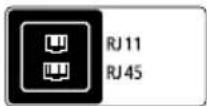

text_image
Laserliner®!
natural_image
Close-up of a mechanical component with a highlighted section (no visible text or symbols)Sicherheitshinweise
natural_image
Close-up of a DURACELL PROCELL battery mounted on a white mechanical device (no visible text or symbols beyond branding)Empfänger RECV
natural_image
Close-up of a DURACELL PROCELL battery component with black and white casing (no visible text or symbols on body)2 ON / OFF
natural_image
Interior hallway view with tiled floor, doors, speakers, and a chair (no text or symbols)natural_image
Close-up of a white electrical outlet connected to a small electronic device (no visible text or symbols)
natural_image
Close-up of hands holding a pen and spines, no visible text or symbols
natural_image
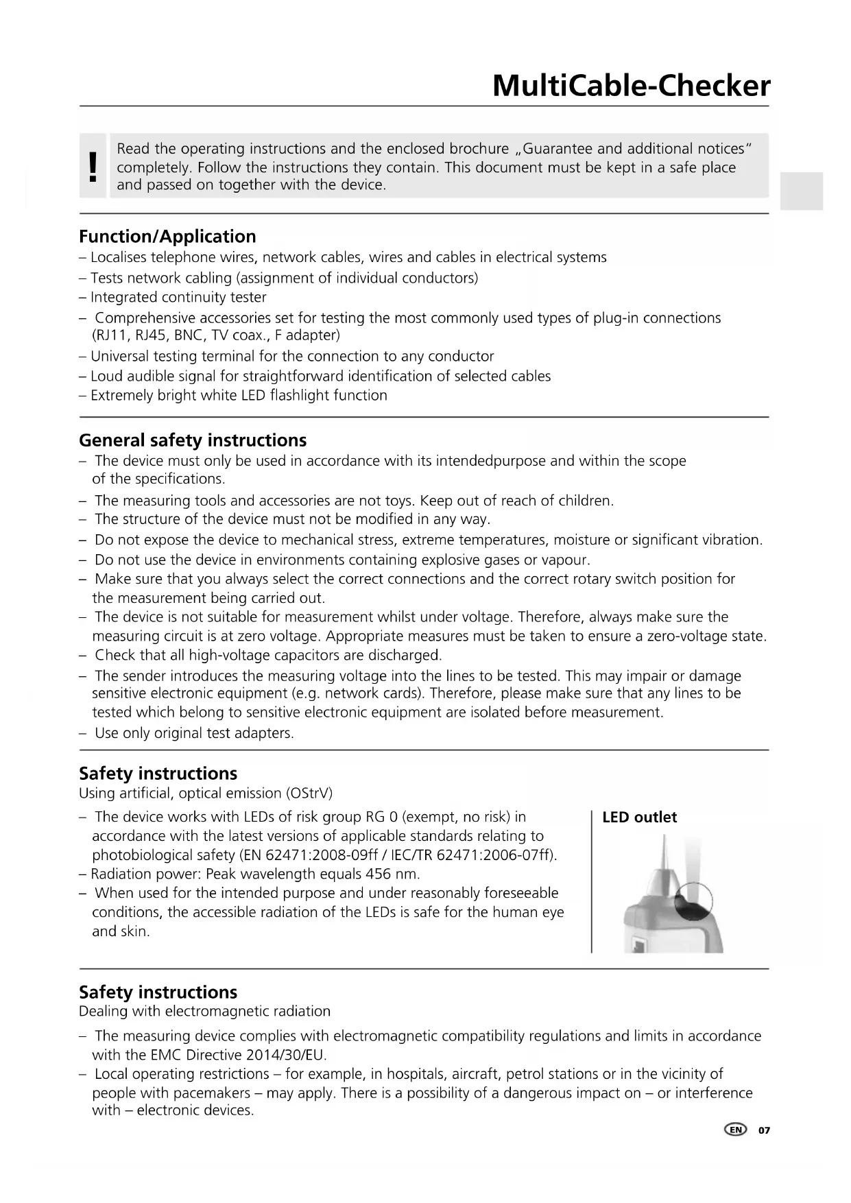
Close-up of a handheld electronic device with wires in the background (no visible text or symbols)Read the operating instructions and the enclosed brochure „Guarantee and additional notices“ completely. Follow the instructions they contain. This document must be kept in a safe place and passed on together with the device.
Function/Application
- Localises telephone wires, network cables, wires and cables in electrical systems
– Tests network cabling (assignment of individual conductors) - Integrated continuity tester
- Comprehensive accessories set for testing the most commonly used types of plug-in connections (RJ11, RJ45, BNC, TV coax., F adapter)
– Universal testing terminal for the connection to any conductor
– Loud audible signal for straightforward identification of selected cables - Extremely bright white LED flashlight function
General safety instructions
- The device must only be used in accordance with its intended purpose and within the scope of the specifications.
- The measuring tools and accessories are not toys. Keep out of reach of children.
- The structure of the device must not be modified in any way.
- Do not expose the device to mechanical stress, extreme temperatures, moisture or significant vibration.
- Do not use the device in environments containing explosive gases or vapour.
- Make sure that you always select the correct connections and the correct rotary switch position for the measurement being carried out.
- The device is not suitable for measurement whilst under voltage. Therefore, always make sure the measuring circuit is at zero voltage. Appropriate measures must be taken to ensure a zero-voltage state.
- Check that all high-voltage capacitors are discharged.
- The sender introduces the measuring voltage into the lines to be tested. This may impair or damage sensitive electronic equipment (e.g. network cards). Therefore, please make sure that any lines to be tested which belong to sensitive electronic equipment are isolated before measurement.
- Use only original test adapters.
Safety instructions
Using artificial, optical emission (OStrV)
- The device works with LEDs of risk group RG 0 (exempt, no risk) in accordance with the latest versions of applicable standards relating to photobiological safety (EN 62471:2008-09ff / IEC/TR 62471:2006-07ff).
– Radiation power: Peak wavelength equals 456 nm. - When used for the intended purpose and under reasonably foreseeable conditions, the accessible radiation of the LEDs is safe for the human eye and skin.
LED outlet
natural_image
Close-up of a mechanical component with a highlighted circular area (no visible text or symbols)Safety instructions
Dealing with electromagnetic radiation
- The measuring device complies with electromagnetic compatibility regulations and limits in accordance with the EMC Directive 2014/30/EU.
- Local operating restrictions – for example, in hospitals, aircraft, petrol stations or in the vicinity of people with pacemakers – may apply. There is a possibility of a dangerous impact on – or interference with – electronic devices.
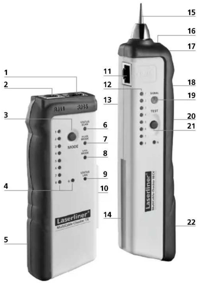
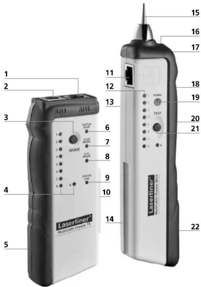
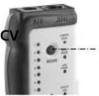
Transmitter TX Receiver RECV
text_image
1 2 3 4 5 RJ11 RJ45 MODE STATUS SCAN ACOR MODE LAIN MODE STATUS LAN 6 7 8 9 10 11 12 13 14 15 16 17 18 19 20 21 SIGNAL TEST Laserliner MultiCable-Chester HCV 22Transmitter TX
1 RJ45 cable connection
2 RJ11 cable connection
3 ON/OFF button / MODE button (SCAN/LAN TEST selection)
4 Cable sequence LEDs
5 Battery compartment (rear)
6 SCAN status LED
7 SCAN mode LED
8 LAN TEST mode LED
9 LAN TEST status LED
10 Connector for receiver RECV
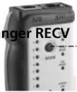
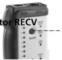
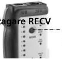
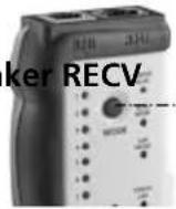
Receiver RECV
11 RJ45 cable connection
12 Cable sequence LEDs RJ 45
13 Speaker (rear)
14 Holder for transmitter TX
15 Test prod
16 Flashlight
17 Headphones jack
18 Receiver signal volume control
19 Receive signal status LED
20 Flashlight ON/OFF switch
21 Test mode button
22 Battery compartment (rear)
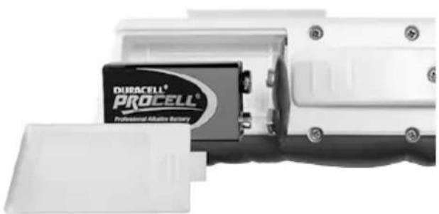
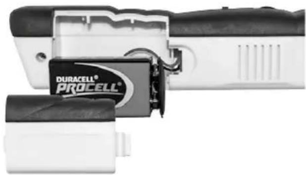
1 Insert battery
Open the battery compartment on the housing's rear side and insert a 9V battery.
Correct polarity must be observed.
Transmitter TX
The SCAN status LED or the LAN TEST mode LED flashes slowly corresponding to the selected mode.
natural_image
Close-up of a DUBACELL PROCELL battery mounted on a white electronic device (no visible text or symbols on the battery itself)Receiver RECV
The signal volume becomes lower despite the fact that the position of the device or the volume control (18) has not changed.
natural_image
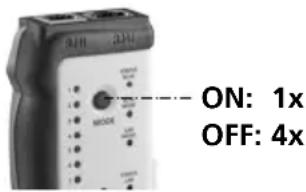
Close-up of a DURACELL PROCELL battery holder and charging device (no visible text or symbols on body)2 ON / OFF
Transmitter TX Receiver RECV
ON: 1x
OFF: 4x
The device is ready for use immediately once the batteries have been inserted. It does not have a separate ON/OFF switch and is therefore always active.
3 Checking the cable configuration for LAN cables
Connect the LAN cable (RJ45) to the sender and receiver, and switch the sender to LAN TEST mode. Press the MODE button (3) until the LAN TEST mode LED (8) lights and the LAN TEST status LED (9) flashes. Now compare the light sequence of diodes 1 to 8 on the sender and receiver.
There is continuity in the cable if:
- The light sequences of the sender and receiver are the same: 1 = 1, 2 = 2 etc.
- The light sequences of the sender and receiver are different, e.g. 1=8, 2=7, etc: cable connections crossed.
- If the G diode also lights up on both devices, the cable is shielded.
There is no continuity in the cable if:
- Diodes 1 to 8 do not light up: cable is damaged, e.g. as a result of a cable break or a connector without a contact.
- Multiple diodes (1 to 8) flash at the same time and at irregular intervals: short-circuit in cable.
Tip 1: In LAN TEST mode, the speed of the light sequence can be adjusted by pressing the button (3). The sequence speed is differentiated by the LAN TEST status LED (9) flashing slowly and quickly.

Do not perform any measurements in the vicinity of or directly adjacent to live or signal-carrying cables. There is a risk of fatal electric shocks and damage to the device.
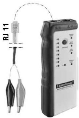
4 Continuity test
text_image
RJ 11 LaserlessOnly the sender is required for this application. Connect the cable terminals to the RJ11 connection and to the object to be tested, and switch the device to LAN TEST mode. Press the MODE button (3) until the LAN TEST mode LED (8) lights and the LAN TEST status LED flashes.
Then keep the MODE button (3) pressed until the LAN TEST status LED (9) lights continuously. The test circuit is closed when the LAN TEST status LED (9) lights up. The test circuit is open if the LAN TEST status LED (9) does not light. Refer to Tip 1.
LAN TEST mode LED (8) ON
LAN TEST mode
LED (8) OFF
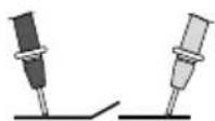
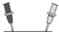
5 Trace cables

- Make the measuring circuit zero-potential.
- Shields in the cable and in the surrounding area (metal coverings, metal supports, etc.) reduce the range of the receiver.
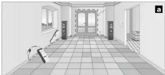
Connect the cable terminals to the sender's RJ11 connection and to the required line, and switch the sender to SCAN mode. Press the MODE button (3) until the SCAN mode LED (7) lights and the SCAN status LED (6) flashes. Then use the receiver to search for the line, with the test mode button (21) held down (see Fig. a). To achieve the maximum measuring depth, set the receiver signal volume as high as it will go (18).
natural_image
Interior hallway view with tiled floor, doors, speakers, and wall-mounted equipment (no visible text or symbols)Tip 2: Depending on the application concerned, it may be advisable to change the type of signal. In SCAN mode keep the MODE button (3) pressed until the SCAN status LED (6) lights continuously. The signal type is reset by briefly pressing the MODE button (3). The SCAN status LED (6) flashing indicates a modulated signal; if it lights continuously this indicates a constant signal.
6 Locating network, telephone and multimedia cables, and individual wires
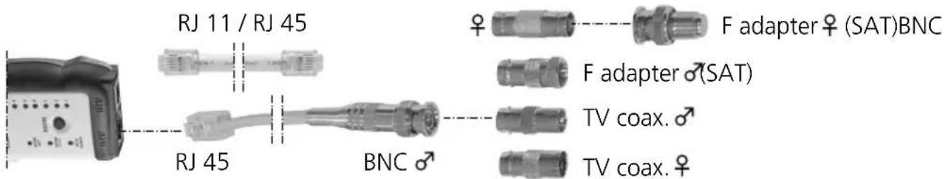
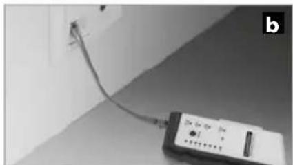
Connect the adapter cable or cable to be located to the sender and switch the device to SCAN mode. If necessary, connect the sender to a network or telephone socket (see Fig. b). For measurements using the cable terminals, connect the red terminal to the cable to be located and connect the black one to earth (earthing conductor or shielding). Then use the receiver to search for the connected cable. See also Tip 2.
text_image
RJ 11 / RJ 45 RJ 45 BNC F adapter ♀ (SAT)BNC F adapter ♂(SAT) TV coax. ♀ TV coax. ♀The lead transmission signal that is fed in may be transmitted to other cables if they are parallel to the lead over longer distances.
natural_image
Close-up of a handheld electronic device connected to a wall-mounted cable (no visible text or symbols)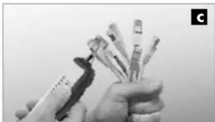
natural_image
Close-up of hands holding several small cylindrical objects, possibly medical or laboratory instruments (no visible text or symbols)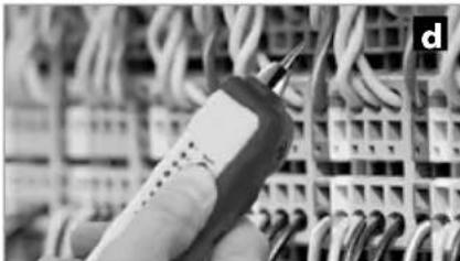
natural_image
Close-up of a handheld electronic device with wires in the background (no visible text or symbols)Tip 3: To locate the cable more efficiently, gradually reduce the receiver signal volume using the control (18). The cable can be located by means of volume differences and is indicated by the status LED (19) lighting up at its brightest or by the maximum signal volume.
Tip 4: The best search results are achieved when the test prod (15) has a direct metallic contact with the cable being located. This type of contact will produce a clearly audible jump in the signal. You can also get stronger signals at the cable ends (Fig. c) or directly at the individual wires (Fig. d).
Tip 5: Any interference that occurs (buzzing, etc.) can be reduced by earthing the return conductor or shielding conductor in the test lead. Earthing by means of your own hand or finger may be enough, however.
Tip 6: Parallel supply lines may generate buzzing interference in the test lead. If the external interference is too great, switch off the household power supply during measurement if possible.
Tip 7: TV sockets in particular may contain filters that have a negative effect on measurements. In this case, remove the TV socket and perform the measurement directly at the cable.
7 Headphones
The headphones supplied enable you to analyse the receiver signals more accurately. IMPORTANT: Set the volume control as low as it will go before connecting the headphones to the receiver (17) and putting them on. An excessively high volume in the headphones may damage your hearing.
Information on maintenance and care
Clean all components with a damp cloth and do not use cleaning agents, scouring agents and solvents. Remove the battery(ies) before storing for longer periods. Store the device in a clean and dry place.
| Technical data (Technical revisions reserved. 05.17) | |
| Transmitter TX | |
| Max. input voltage 20V DC | |
| Max. output current 10 mA | |
| Max. signal voltage 8 Vss (peak-to-peak) | |
| Max. testing length 3 km | |
| Power supply 1 x 9V block, IEC LR6, Alkali | |
| Dimensions (W x H x D) 49 x 127 x 34 mm | |
| Weight (incl. battery) 130 g | |
| Receiver RECV | |
| Max. input voltage 20V DC | |
| Max. output current 30 mA | |
| SCAN mode measuring range 0 ... 5 cm measuring depth | |
| Power supply 1 x 9V block, IEC LR6, Alkali | |
| Dimensions (W x H x D) 39 x 187 x 30 mm | |
| Weight (incl. battery) 135 g | |
| Transmitter TX / Receiver RECV | |
| Operating conditions | 0°C ... 50°C, Max. humidity 80% rH,no condensation, max. altitude 2000 m |
| Storage conditions -10°C ... 60°C, Max. humidity 80% rH | |
EU directives and disposal
This device complies with all necessary standards for the free movement of goods within the EU.
This product is an electric device and must be collected separately for disposal according to the European Directive on waste electrical and electronic equipment.
Further safety and supplementary notices at:
http://laserliner.com/info?an=mucache
text_image
CE — — —!
natural_image
Close-up of a mechanical component with a highlighted section (no visible text or symbols)natural_image
Close-up of a DURACELL PROCELL battery mounted on a white electronic device (no visible text or symbols beyond branding)Ontvanger RECV
natural_image
Close-up of a DURACELL PROCELL battery component with black and white casing (no visible text or symbols on body)2 ON / OFF
Zender TX Ontvar
ON: 1x
OFF: 4x
text_image
RJ 11 Laser Group Laser Group Test Test Power Output Control Output Output Outputnatural_image
Interior hallway view with tiled floor, doors, speakers, and wall-mounted equipment (no visible text or symbols)natural_image
Close-up of a small electronic device connected to a wall-mounted cable, no visible text or symbols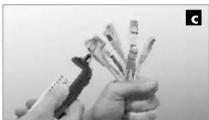
natural_image
Close-up of hands holding multiple small electronic components (no visible text or symbols)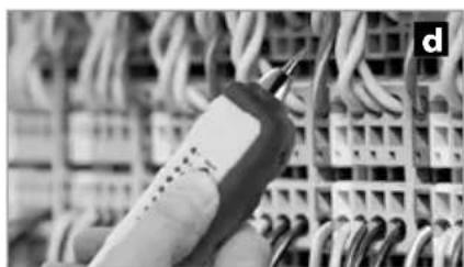
natural_image
Close-up of a handheld electronic device connected to a grid of wires (no visible text or symbols)natural_image
Close-up of a mechanical component with a highlighted circular area (no visible text or symbols)natural_image
Close-up of a DUBACELL PROCELL battery component with open casing (no visible text or symbols on body)Modtager RECV
natural_image
Close-up of a DURACELL PROCELL battery pack assembly (no visible text or symbols on the main body)2 ON / OFF
Sender TX Modta

ON: 1x
OFF: 4x
natural_image
Interior hallway view with tiled floor, doors, speakers, and a robot (no text or symbols)natural_image
Close-up of a handheld electronic device connected to a wall-mounted cable (no visible text or symbols)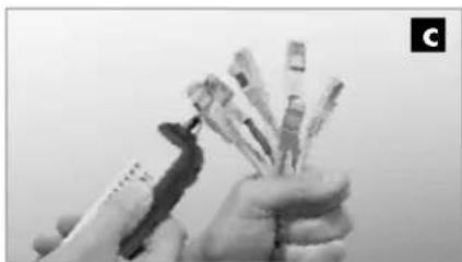
natural_image
Close-up of hands holding multiple sticks, no visible text or symbols
natural_image
Close-up of a handheld electrical probe touching wires in a grid (no visible text or symbols)natural_image
Close-up of a mechanical component with a highlighted section (no visible text or symbols)natural_image
Close-up of a DURACELL PROCELL battery mounted on a white electronic device (no visible text or symbols beyond branding)Récepteur RECV
natural_image
Close-up of a DURACELL PROCELL battery component with black and white casing (no visible text or symbols)text_image
RJ 11 Linear Generatornatural_image
Interior view of a room with tiled floor, wall-mounted speakers, and a chair (no text or symbols)natural_image
Close-up of a small electronic device connected to a wall-mounted cable, no visible text or symbols
natural_image
Close-up of hands holding a bundle of cards or cards with a pen, no visible text or symbols
natural_image
Close-up of a handheld electrical connector with wires in the background (no visible text or symbols)natural_image
Close-up of a mechanical component with a highlighted section (no visible text or symbols)natural_image
Close-up of a DURACELL PROCELL battery mounted on a white industrial device (no visible text or symbols beyond branding)Receptor RECV
natural_image
Close-up of a DURACELL® PROCELL battery component with attached circuit board (no visible text or symbols beyond branding)2 ON / OFF
Emisor TX Receptor RECV
ON: 1x
OFF: 4x
natural_image
Interior hallway view with tiled floor, doors, speakers, and a guitar (no text or symbols)natural_image
Close-up of a small electronic device connected to a wall-mounted cable, no visible text or symbols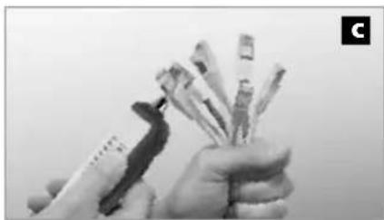
natural_image
Close-up of hands holding various small electronic components (no visible text or symbols)
natural_image
Close-up of a handheld electronic device connected to a grid of wires (no visible text or symbols)natural_image
Close-up of a mechanical component with a highlighted circular area (no visible text or symbols)natural_image
Close-up of a DURACELL PROCELL battery mounted on a white electronic device (no visible text or symbols beyond branding)Ricevitore RECV
natural_image
Close-up of a DURACELL PROCELL battery pack assembly (no visible text or symbols on the main body)natural_image
Interior hallway view with tiled floor, doors, speakers, and a chair (no text or symbols)text_image
RJ 11 / RJ 45 BNC ♀ Adattatore F ♀ (SAT) Adattatore F ♂(SAT) Coax TV ♂ Coax TV ♀ RJ 45 BNC ♂natural_image
Close-up of a wall-mounted electrical component connected to a cable, no visible text or symbols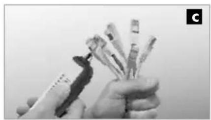
natural_image
Close-up of hands holding several small cylindrical objects, possibly medical or laboratory instruments (no visible text or symbols)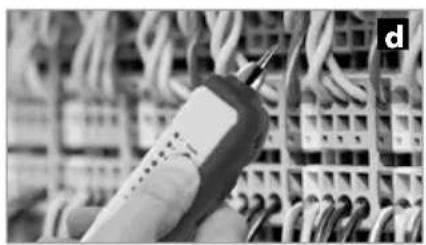
natural_image
Close-up of a handheld electronic device with wires in the background (no visible text or symbols)text_image
CE RECOLOGY RECOLOGY RECOLOGY!
natural_image
Close-up of a mechanical component with a highlighted circular area (no visible text or symbols)natural_image
Close-up of a DURACELL PROCELL battery mounted on a white mechanical device (no visible text or symbols on the battery itself)Odbiornik RECV
natural_image
Close-up of a DURACELL PROCELL battery pack with attached circuit board (no visible text or symbols)2 ON / OFF
Nadajnik TX Odbiornik RECV

ON: 1x
OFF: 4x
natural_image
Interior hallway view with tiled floor, doors, speakers, and a robot (no text or symbols)natural_image
Close-up of a handheld electronic device connected to a wall-mounted cable (no visible text or symbols)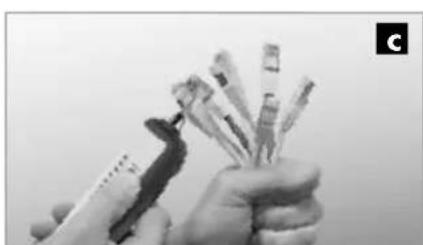
natural_image
Close-up of hands holding multiple small electronic components (no visible text or symbols)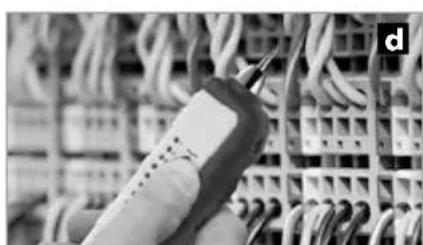
natural_image
Close-up of a handheld electronic device connected to a grid of cables (no visible text or symbols)natural_image
Close-up of a mechanical component with a highlighted section (no visible text or symbols)Turvallisuusohjeet
natural_image
Close-up of a DURACELL PROCELL battery mounted on a white electronic device (no visible text or symbols beyond branding)Vastaanotin RECV
natural_image
Close-up of a DURACELL PROCELL battery component with black and white casing (no visible text or symbols)2 ON / OFF
natural_image
Interior hallway view with tiled floor, wall-mounted speakers, and window (no text or symbols)natural_image
Close-up of a handheld electronic device connected to a wall-mounted cable (no visible text or symbols)
natural_image
Close-up of hands holding a pen and multiple test tubes (no visible text or symbols)
natural_image
Close-up of a handheld electronic device connected to a grid of wires (no visible text or symbols)natural_image
Close-up of a mechanical component with a highlighted section (no visible text or symbols)natural_image
Close-up of a DURACELL PROCELL battery mounted on a white industrial device (no visible text or symbols beyond branding)Recetor RECV
natural_image
Close-up of a DURACELL PROCELL battery pack with black and white casing (no visible text or symbols on body)2 ON / OFF Emissor TX
text_image
ON: 1x OFF: 4xRecetor RECV
natural_image
Interior hallway view with tiled floor, doors, and speakers (no visible text or symbols)natural_image
Close-up of a white electrical terminal with a cable and indicator device connected to a wall (no visible text or symbols)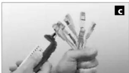
natural_image
Close-up of hands holding multiple small electronic components (no visible text or symbols)
natural_image
Close-up of a handheld electronic device with wires in the background (no visible text or symbols)text_image
CE RECOLOGY RECOLOGY RECOLOGY!
natural_image
Close-up of a mechanical component with a highlighted section (no visible text or symbols)text_image
1 2 3 4 5 RJ11 RJ45 MODE STATUS SCAN SCAN MODE SAIN SAIN SAIN SAIN SAIN SAIN SAIN SAIN SAIN SAIN SAIN SAIN SAIN SAIN SAIN SAIN SAIN SAIN SAIN SAIN SAIN SAIN SAIN SAIN SAIN SAIN SAIN SAIN SAIN SAIN SAIN SAIN SAIN SAINSändare TX
natural_image
Close-up of a DURACELL PROCELL battery component with open lid (no visible text or symbols on body)Mottagare RECV
natural_image
Close-up of a DURACELL PROCELL battery pack with black and white casing (no visible text or symbols on body)2 ON / OFF
Sändare TX Mottagare RECV
ON: 1x
OFF: 4x
text_image
RJ 11 ULSAN-Genusnatural_image
Interior hallway view with tiled floor, wall-mounted speakers, and a robotic arm (no text or symbols)natural_image
Close-up of a cable with a small electronic device connected to a wall-mounted cable (no visible text or symbols)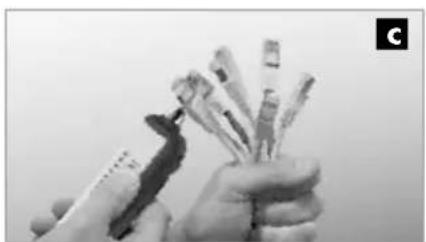
natural_image
Close-up of hands holding multiple pens or pens (no visible text or symbols)
natural_image
Close-up of a handheld electronic device with wires in the background (no visible text or symbols)natural_image
Close-up of a mechanical component with a highlighted circular area (no visible text or symbols)Sender TX Mottaker RECV
text_image
1 2 3 4 5 RJ11 RJ45 MODE STATUS SCAN SCAN MODE STATUS LAN 6 7 8 9 10 11 12 13 14 15 16 17 18 19 20 21 22 Laserliner MultiCable Checker TXSender TX
1 RJ 45 kabelforbindelse
2 RJ 11 kabelforbindelse
3 PÅ/AV-knapp / MODE-knapp (omstilling SCAN / LAN-TEST)
4 Indikator kabelsekvens
5 Batterirom (bakside)
6 Statusindikator SCAN
7 Modusindikator SCAN
8 Modusindikator LAN-TEST
9 Statusindikator LAN-TEST
10 Forbindelseselement for mottaker RECV
Mottaker RECV
11 RJ 45 kabelforbindelse
12 Indikator kabelsekvens RJ 45
13 Høyttaler (bakside)
14 Opptak for sender TX
15 Målespiss
16 Lommelykt
17 Uttak for hodetelefoner
18 Volumkontroll mottakssignal
19 Statusindikator mottakssignal
20 PÅ/AV-bryter lommelykt
21 Knapp testmodus
22 Batterirom (bakside)
natural_image
Close-up of a DURACELL PROCELL battery mounted on a white electronic device (no visible text or symbols beyond branding)Mottaker RECV
natural_image
Close-up of a DURACELL PROCELL battery pack assembly (no visible text or symbols on the components)2 ON / OFF
Sender TX Mottal
ON: 1x
OFF: 4x
natural_image
Interior hallway view with tiled floor, wall-mounted speakers, and a robot-like device (no text or symbols)natural_image
Close-up of a white electrical terminal with a cable and indicator lights connected to a wall-mounted device (no visible text or symbols)
natural_image
Close-up of hands holding a bundle of cards or cards with a pen, no visible text or symbols
natural_image
Close-up of a handheld electronic device connected to a grid of wires (no visible text or symbols)natural_image
Close-up of a mechanical component with a highlighted section (no visible text or symbols)natural_image
Close-up of a DURACELL PROCELL battery mounted on a white electronic device (no visible text or symbols beyond branding)Alici RECV
natural_image
Close-up of a DURACELL PROCELL battery component with black and white casing (no visible text or symbols on body)2 ON / OFF TX Verici Alici RECV
ON: 1x OFF: 4x
natural_image
Interior hallway view with tiled floor, wall-mounted speakers, and a person holding a device (no text or symbols visible)natural_image
Close-up of a white electronic device connected to a wall-mounted cable, no visible text or symbols
natural_image
Close-up of hands holding a pen and spines, no visible text or symbols
natural_image
Close-up of a handheld electronic device connected to a grid of wires (no visible text or symbols)natural_image
Interior view of a room with sound equipment and tiled flooring, no visible text or symbolsSERVICE


Umarex GmbH & Co. KG
- Laserliner -