P5611OTR - Receiver Emos - Free user manual and instructions
Find the device manual for free P5611OTR Emos in PDF.
| Product type | Wireless thermostat receiver |
| Brand | Emos |
| Model | P5611OTR |
| Dimensions (switching unit) | 37 × 115 × 91 mm |
| Weight (switching unit) | 150 g |
| Power supply | 230 V AC / 50 Hz |
| Max. switched load | 230 V AC ; 16 A (resistive), 5 A (inductive) |
| Operating temperature | 0 °C to 40 °C |
| Storage temperature | -10 °C to 60 °C |
| Radio frequency | 868 MHz, 25 mW e.r.p. max. |
| Pairing capacity | Up to 6 receivers |
| Range in open space | Up to 100 m |
| Main functions | Automatic pairing, communication test, memory erasure |
| Maintenance and cleaning | Soft, slightly damp cloth; do not use solvents |
| Safety | Disconnect power before installation; do not expose to weather; do not open; repair by a qualified specialist |
| Compatibility | Wireless thermostat P56110T |
| Battery type (control unit) | 2 AA 1.5 V batteries (alkaline, non-rechargeable) |
Frequently Asked Questions - P5611OTR Emos
User questions about P5611OTR Emos
0 question about this device. Answer the ones you know or ask your own.
Ask a new question about this device
Download the instructions for your Receiver in PDF format for free! Find your manual P5611OTR - Emos and take your electronic device back in hand. On this page are published all the documents necessary for the use of your device. P5611OTR by Emos.
USER MANUAL P5611OTR Emos
natural_image
Simple line drawing of a pendulum with a circular inset showing a book symbol (no text or labels)rear part zadní část zadná časť tylna część hátulsó rész zadnji del stražnji dio Rückseite нижня частина partea din spate galinė dalis aizmugure tagakülg задна част partie arrière parte posteriore parte trasera achterste gedeelte
text_image
ON OFF ID 1 2 33
GB | Wireless Receiver
Designed for P56110T wireless thermostat.
Important
- Before first use, make sure to read carefully the Operating Manual for the thermostat, as well as the manual for the boiler or air-conditioning equipment.
- Turn off power before installing the thermostat!
• Installation should be carried out by a qualified professional! - Abide by prescribed standards during installation.
- You can find more detailed instructions in the P56110T thermostat's manual.
SPECIFICATIONS
Switched load: max. 230 V AC; 16 A for resistive load; 5 A for inductive load
Operating temperature: 0 °C to 40 °C
Storage temperature: -10 °C to 60 °C
Unit interconnection: via 868 MHz radio signal, max. 25 mW e.r.p.
Pairing capacity: max. 6 receivers
Power supply: switching unit (receiver) 230 V AC/50 Hz
Dimensions and weight: switching unit: 37 × 115 × 91 mm; 150 g
Control (Portable) Unit
(see Fig. 1)
1-day of the week 12-set temperature
2 – clock 13 – frost indication
3-comfort mode 14-operation status icon
4 – economy mode 15 – battery status indication
5 – manual control 16 – current room temperature
6 – programme preset 17 – day profile
7-comfort/economy mode switch 18-DOWN button
8 – UP button 19 – change temperature
9 – change clock 20 – illuminate screen
10 - change programme 21 - RESET
11 - wireless communication icon
Removing the Rear Cover of the Control Unit
(see Fig. 2)
- Use a screwdriver to press and hold the inner lock.
- Remove the front cover.
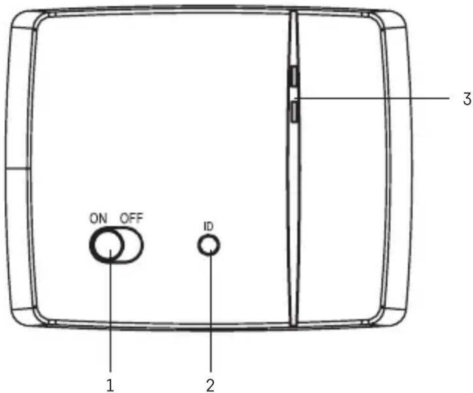
Switching Unit
(see Fig. 3)
1 – main switch 3 – LED indicators
2 - pairing button
LED Indicators
- Blue LED indicates the switching unit is powered by 230 V AC. If the unit is not connected to power or if the main switch is in the OFF position, the blue LED is not lit.
- Red LED is lit while the heating/air-conditioning system is active.
Main Switch
If the heating/air-conditioning system is not used for an extended period of time, it is recommended to turn the switching unit off (move the main switch to the OFF position).
INSTALLATION
Pairing the Control Unit with the Switching Unit
Pairing enables transmission of information between the control unit and the switching unit.
The units pair automatically (self-learning) after pressing the "ID" button.
Attention: When pairing two or more receivers, it is necessary to have pairing mode activated on all receivers simultaneously!
- Insert 2× 1.5 V AA batteries into the control unit (make sure polarity of the batteries is correct). Use alkaline batteries only, not rechargeable ones.
- Connect the switching unit correctly to the power source, and press and hold the "ID" button; the top red LED starts flashing.
Long-press the screen illumination button ( 🔍 ) on the control unit within 10 seconds.
Both units will automatically pair and the •) icon will be displayed. The red LED on the switching unit will stop flashing and goes out.
If the pairing of the units fails, the •) icon will be flashing instead.
Testing Wireless Communication between the Units
- Use the ▲ button to select a temperature a few degrees higher than the current room temperature.
- Wait for approximately 10 seconds or press the / button.
- The red LED on the switching unit will light up.
- If the LED does not light up, move the control unit closer to the switching unit. Press the button to set a value which is lower than the room temperature – the receiver must switch off.
- Repeat steps 1 to 4.
The maximum range between the control and switching unit is 100 m in an open space. The range may decrease indoors as the signal has to pass through walls and other obstacles.
- Press the "RESET" button once the test is complete.
Deleting the Memory (Code) of Paired Units
To delete the pairing code used between the control and switching unit, follow the instructions below. Press and hold the "ID" button on the switching unit; the red LED will start flashing. Short press the "ID" button again within 10 seconds. The red LED will stop flashing and goes out. The pairing code is deleted.
Mounting the Switching Unit onto the Wall
- Remove the rear cover of the switching unit.
- Mark positions for holes.
- Drill two holes, carefully insert the plastic wall plugs into them and use two screws to mount the rear cover of the switching unit.
- Connect the wires to the labelled terminals according to the wiring diagram.
- Complete the installation by fitting the switching unit onto the mounted rear cover.
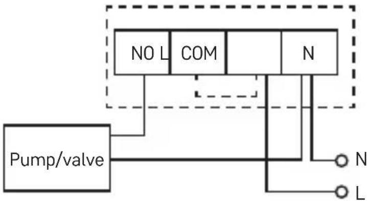
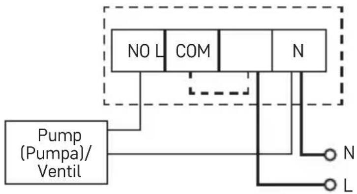
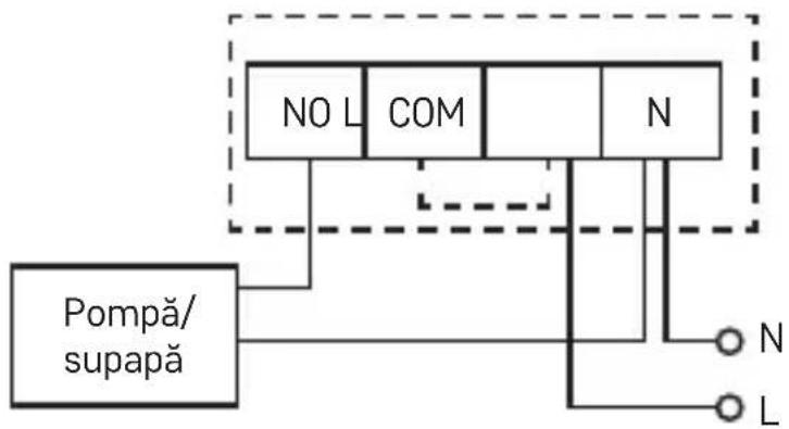
Wiring Diagram
The P56110T thermostat can be used with any one-stage heating or air-conditioning system.
NO – switched contact COM – contact for the switch
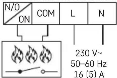
text_image
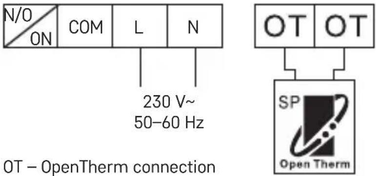
N/O ON COM L N 230 V~ 50-60 Hz 16 (5) AL - 230 V AC power connection N - neutral conductor
text_image
OT OT SP Open ThermPump/Motorised Valve Wiring Diagram
flowchart
graph TD
    A["Pump/valve"] --> B["NO L"]
    A --> C["COM"]
    A --> D["N"]
    B --> E["N"]
    C --> F["L"]
    D --> G["N"]
    style A fill:#f9f,stroke:#333
    style B fill:#ccf,stroke:#333
    style C fill:#ccf,stroke:#333
    style D fill:#ccf,stroke:#333
    style E fill:#fff,stroke:#333
    style F fill:#fff,stroke:#333
    style G fill:#fff,stroke:#333
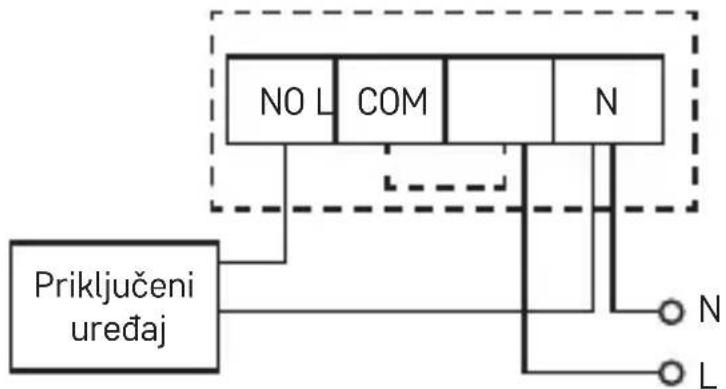
Floor Heating Wiring Diagram

flowchart
graph TD
    A["connected device"] --> B["NO L"]
    A --> C["COM"]
    A --> D["N"]
    B --> E["N"]
    C --> F["L"]
    D --> G["N"]
    style A fill:#f9f,stroke:#333
    style B fill:#ccf,stroke:#333
    style C fill:#ccf,stroke:#333
    style D fill:#ccf,stroke:#333
    style E fill:#fff,stroke:#333
    style F fill:#fff,stroke:#333
    style G fill:#fff,stroke:#333
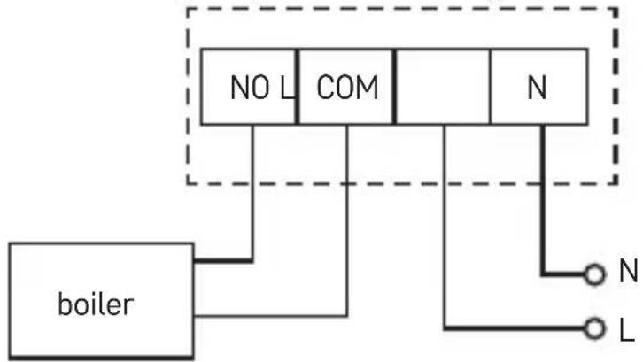
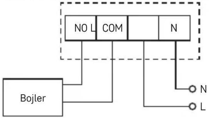
Boiler Wiring Diagram (Zero Voltage Switching)
flowchart
graph TD
    A["boiler"] --> B["NO L"]
    A --> C["COM"]
    A --> D["N"]
    B --> E["N"]
    C --> F["L"]
    D --> G["N"]
    style A fill:#f9f,stroke:#333
    style B fill:#ccf,stroke:#333
    style C fill:#ccf,stroke:#333
    style D fill:#ccf,stroke:#333
    style E fill:#fff,stroke:#333
    style F fill:#fff,stroke:#333
- The pre-installed wire coupler between COM and L will not be connected.
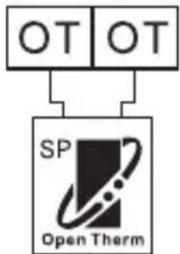
OpenTherm Connection Diagram
text_image
N/O ON COM L N 230 V~ 50-60 Hz OT - OpenTherm connection OT OT SP Open ThermUpkeep and Maintenance
The product is designed to serve reliably for many years if used properly. Here are some tips for proper operation:
- Read the manual carefully before using this product.
- Do not expose the product to direct sunlight, extreme cold and humidity, and sudden changes in temperature. This would reduce measuring accuracy.
-
Do not place the product in locations prone to vibration and shocks – may cause damage.
-
Do not subject the product to excessive force, impacts, dust, high temperatures or humidity – doing so may cause malfunction, shorten battery life, damage the batteries or deform the plastic parts.
- Do not expose the product to rain or high humidity, dropping or splashing water.
- Do not place any open flame sources on the product, e.g. a lit candle, etc.
- Do not place the product in places with inadequate air flow.
- Do not insert any objects in the product's vents.
- Do not tamper with the internal electric circuits of the product – doing so may damage the product and will automatically void the warranty.
- The product should only be repaired by a qualified professional.
- To clean the product, use a slightly moistened soft cloth. Do not use solvents or cleaning agents – they could erode the plastic parts and cause corrosion of the electric circuits.
- Do not immerse the product in water or other liquids.
- In the event of damage or defect on the product, do not perform any repairs by yourself. Have it repaired in the shop where you bought it.
- This device is not intended for use by persons (including children) whose physical, sensory or mental disability or lack of experience and expertise prevents safe use, unless they are supervised or instructed in the use of the appliance by a person responsible for their safety. Children must always be supervised to ensure they do not play with the device.

Do not dispose with domestic waste. Use special collection points for sorted waste. Contact local authorities for information about collection points. If the electronic devices would be disposed on landfill, dangerous substances may reach groundwater and subsequently food chain, where it could affect human health. Hereby, EMOS spol. s r. o. declares that the radio equipment type P56110TR is in compliance with Directive 2014/53/EU. The full text of the EU declaration of conformity is available at the following internet address: http://www.emos.eu/download.
flowchart
graph TD
    A["OT"] --> C["SP Open Therm"]
flowchart
graph TD
    A["OT"] --> C["SP Open Therm"]
text_image
N/O ON COM L N 230 V~ 50-60 Hz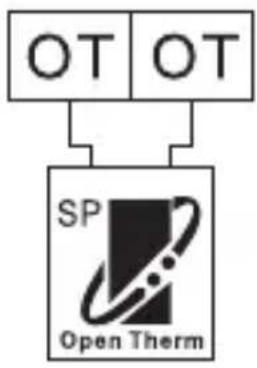
flowchart
graph TD
    A["OT"] --> C["SP Open Therm"]
flowchart
graph TD
    A["OT"] --> C["SP Open Therm"]
    B["OT"] --> C["SP Open Therm"]
flowchart
graph TD
    A["OT"] --> C["SP Open Therm"]
flowchart
graph TD
    A["OT"] --> C["SP Open Therm"]
text_image
N/O ON COM L N 230 V~ 50-60 Hz 16 (5) A OT OT SP Open ThermShema ožičenja za pumpu/motorizirani ventil
flowchart
graph TD
    A["Pump (Pumpa)/Ventil"] --> B["NO L"]
    A --> C["COM"]
    A --> D["N"]
    B --> E["N"]
    C --> F["L"]
    D --> G["N"]
    style A fill:#f9f,stroke:#333
    style B fill:#ccf,stroke:#333
    style C fill:#ccf,stroke:#333
    style D fill:#ccf,stroke:#333
    style E fill:#fff,stroke:#333
    style F fill:#fff,stroke:#333
    style G fill:#fff,stroke:#333
Shema ožičenja za podno grijanje
flowchart
graph TD
    A["NO L"] --> C["Node"]
    B["COM"] --> C
    D["N"] --> C
    E["Priključeni uređaj"] --> C
    C --> F["N"]
    C --> G["L"]
Shema ožičenja za bojler (prebacivanje nultog napona)
flowchart
graph TD
    A["NO L"] --> B["COM"]
    B --> C["N"]
    D["Bojler"] --> E["N"]
    D --> F["L"]
flowchart
graph TD
    A["OT"] --> C["SP Open Therm"]
text_image
N/O ON COM L N 230 V~ 50-60 Hz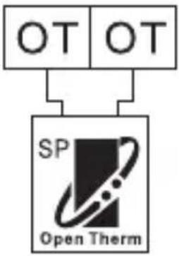
flowchart
graph TD
    A["OT"] --> C["SP Open Therm"]
text_image
OT OT SP Open ThermSchema de conectare a pompei/supapei motorizote
flowchart
graph TD
    A["Pompă/supapă"] --> B["NO L"]
    A --> C["COM"]
    A --> D["N"]
    B --> E["N"]
    C --> F["L"]
    D --> G["N"]
    style A fill:#f9f,stroke:#333
    style B fill:#ccf,stroke:#333
    style C fill:#ccf,stroke:#333
    style D fill:#ccf,stroke:#333
    style E fill:#fff,stroke:#333
    style F fill:#fff,stroke:#333
    style G fill:#fff,stroke:#333
flowchart
graph TD
    A["OT"] --> C["SP Open Therm"]
    B["OT"] --> C["SP Open Therm"]
Siurblio ir motorizuoto vožtuvo prijungimo schema
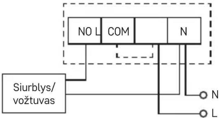
flowchart
graph TD
    A["NO L"] --> B["COM"]
    B --> C["N"]
    D["Siurblys/vožtuvas"] --> E["N"]
    D --> F["L"]
flowchart
graph TD
    A["OT"] --> C["SP Open Therm"]
flowchart
graph TD
    A["OT"] --> C["SP Open Therm"]
flowchart
graph TD
    A["OT"] --> C["SP Open Therm"]
    B["OT"] --> C["SP Open Therm"]
text_image
N/O ON COM L N 230 V~ 50-60 Hz OT – OpenTherm свързване OT OT SP Open Thermflowchart
graph TD
    A["OT"] --> C["SP Open Therm"]
flowchart
graph TD
    A["OT"] --> C["SP Open Therm"]
text_image
N/O ON COM L N 230 V~ 50-60 Hz OT – Collegamento OpenTherm OT OT SP Open ThermCura e manutenzione
1 - interruptor principal
Interruptor principal
flowchart
graph TD
    A["OT"] --> C["SP Open Therm"]
text_image
N/O ON COM L N 230 V~ 50-60 Hzflowchart
graph TD
    A["OT"] --> C["SP Open Therm"]