
MBS 32 F - Drill Fein - Free user manual and instructions
Find the device manual for free MBS 32 F Fein in PDF.
| Product type | Electromagnetic drill stand |
| Brand | Fein |
| Model | MBS 32 F |
| Application | Drilling with core cutters and twist drills, reaming and tapping in magnetic materials |
| Magnetic attraction force | 10,000 N (estimated) |
| Max. drilling diameter (cutter) in steel | 32 mm |
| Max. drilling diameter (twist drill) in steel | 16 mm (estimated) |
| Max. reaming diameter in steel | M20 (estimated) |
| Total travel | 180 mm (estimated) |
| Stand height | 350 mm (estimated) |
| Dimensions of electromagnetic base | 200 x 100 mm (estimated) |
| Weight (without drive machine) | 13 kg (estimated) |
| Magnet supply voltage | 230 V ~ 50 Hz |
| Magnet power consumption | 50 W (estimated) |
| Max. current drawn by drive machine | Depending on machine used (max. 16 A) |
| Recommended electrical protection | Residual current circuit breaker 30 mA |
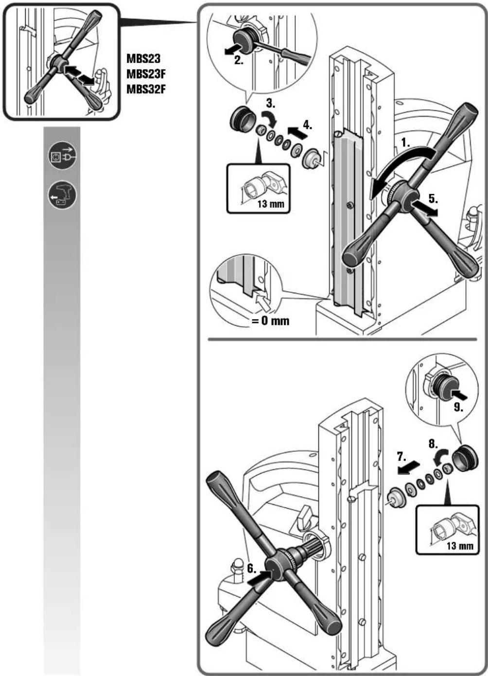
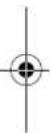
| Included accessories | Safety strap, chip hook, hexagonal key |
| Safety symbols | Read the manual, disconnect before intervention, do not touch rotating parts |
| Maintenance | Cable replacement by a FEIN authorized workshop; clean the base regularly |
| Warranty | Conforms to the legal regulations of the country of marketing |
| Protection rating | IP XX (not specified, use in dry indoor environment) |
Frequently Asked Questions - MBS 32 F Fein
User questions about MBS 32 F Fein
0 question about this device. Answer the ones you know or ask your own.
Ask a new question about this device
Download the instructions for your Drill in PDF format for free! Find your manual MBS 32 F - Fein and take your electronic device back in hand. On this page are published all the documents necessary for the use of your device. MBS 32 F by Fein.
USER MANUAL MBS 32 F Fein
Director of Advanced Technology
FEIN Service
C. & E. Fein GmbH
Hans-Fein-Straße 81
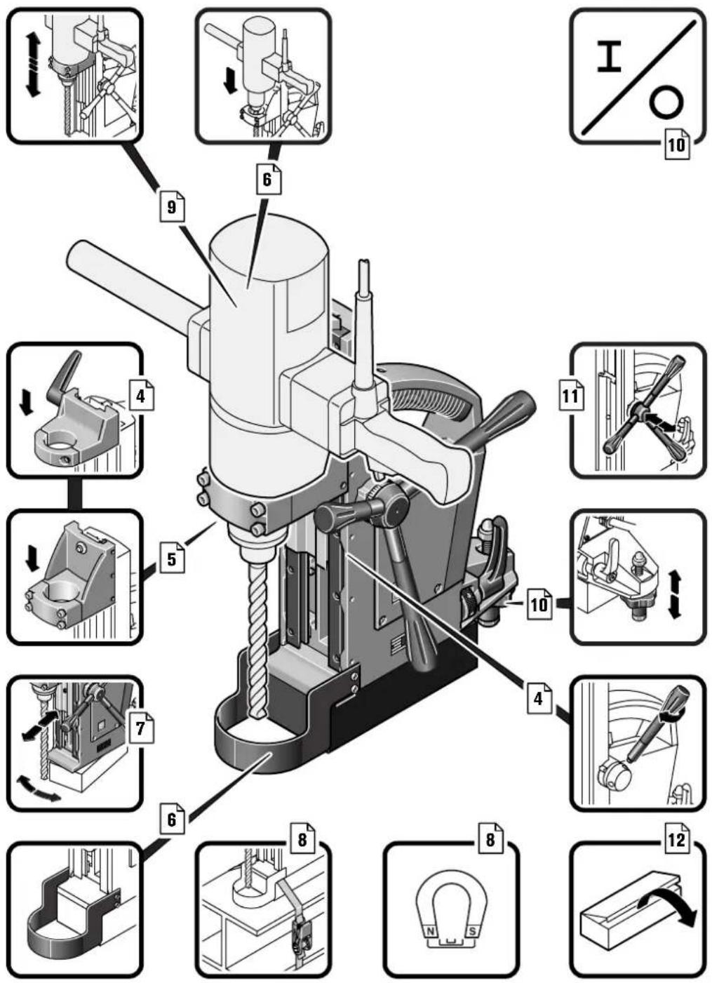
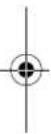
natural_image
3D rendering of a mechanical press or drill press device with no visible text or symbols2
| MBS16 | MBS23 MBS23F MBS32F | ||||
| 9 03 17 9 03 15 9 03 14 9 03 16 | |||||
| P_1 | W 60 60 60 130 | ||||
| I_max | A | 1 | 6 | 1 | 6 |
| kg | 7,9 15,4 14,6 21,8 | ||||
| kg | 3,5 6,5 6,5 11 | ||||
| N | 9000 12000 12000 18000 | ||||
| Fe HSS | mm | 12-32 12-65 12-65 12-65 | |||
| Fe HSS | mm | 16 23 23 32 | |||
| mm | 16 23 23 40 | ||||
| Fe HSS | M 12 M 20 M 20 M 24 | ||||
| mm | 373 438 406 513 | ||||
| mm | 135 178 178 178 | ||||
| mm | 270 362 330 365 | ||||
| ° | -8-350 | ||||
| mm | - | 6 | - | 1 | |
| I x b | mm | 160 x 80 184 x 92 184 x 92 | 220 x 100 | ||
| mm | 43 53 53 63 | ||||
1
6
1
0


3


MBS16
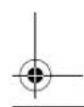
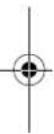
3.
1.
2.
5.
6.
4.


6


MBS16
MBS23
MBS23F
MBS32F
10


12


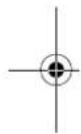
Original Instructions for Magnetic Drill Stand.
Symbols, abbreviations and terms used.
| Symbol, character Explanation | |
 | Make sure to read the enclosed documents such as the Instruction Manual and the General Safety Instructions. |
| [KAS4] | Observe the Instructions in the text or graphic opposite! |
 | Observe the instructions in the text or graphic opposite! |
 | Do not touch the rotating parts of the power tool. |
 | Before commencing this working step, pull the mains plug out of the socket. Otherwise there will be danger of injury if the power tool should start unintentionally. |
| [HZ30] | Before commencing this working step, remove the battery from the power tool. Otherwise there is danger of injury if the power tool should start accidentally. |
 | This sign indicates a possible dangerous situation that could cause severe or fatal injury. |
| [0ZDD] | Confirms the conformity of the power tool with the directives of the European Community. |
| [AZ8A] | Worn out power tools and other electrotechnical and electrical products should be sorted separately for environment-friendly recycling. |
| [SAa] | Product with basic insulation and exposed (touchable), conductive parts additionally connected to the protective earth conductor. |
 | Provided accessories |
| Character Unit of measure, international | Unit of measure, national | Explanation | |
| P_1 | W W Power input | ||
| I_max | A A Max. power consumption of the drive motor | ||
| kg kg Weight according to EPTA-Procedure 01 | |||
 | kg kg Max. weight of the drive motor | ||
| [47ZT] | N N Magnetic holding power | ||
| ∅ | mm mm Diameter of a round part | ||
 | mm mm Drilling capacity in steel - TCT (core drill bit) | ||
 | mm mm Drilling capacity in steel – high speed steel (HSS)(twist drill bit) | ||
 | mm mm Diameter for reaming | ||
 | mm mm Bolt hole diameter in steel | ||
| M... mm mm Size of metric thread | |||
| [AC64] | mm mm Height of drill stand | ||
| [22D6] | mm mm Stroke (via capstan handle) | ||
 | mm mm Total stroke range | ||
 | ° | ° | Slewing range |
| Character Unit of measure, International | Unit of measure, national | Explanation |
 mm mm Adjustment range mm mm Adjustment range | ||
| I x w mm mm Magnetic foot plate dimensions | ||
 mm mm d mm mm d | _1 =collar diameter of drive motor | |
| m, s, kg, A, mm, V, W, Hz, N, °C, dB, min, m/s ^2 | Basic and derived units of measure from the international system of units SL |
For your safety.
WARNING
Read all safety warnings and all instructions provided with the magnetic drill stand or the power tool. Failure to fol-
low the warnings and instructions may result in electric shock, fire and/or serious injury.
Save all safety warnings and instructions for future reference.

Do not use this product before you have thoroughly read and completely understood this Instruction Manual and the enclosed "General
Safety Instructions" (document number 3 41 30 054 06 1). The documents mentioned should be kept for later use and enclosed with the product, should it be passed on or sold.
Please also observe the relevant national industrial safety regulations.
Intended use of the magnetic drill stand:
Magnetic drill stand for holding a drive motor, for drilling with core drill bits and solid drill bits, reaming and tapping on materials with surfaces suitable for magnets in weather-protected environments using the application tools and accessories recommended by FEIN.
Special safety instructions.
Pull the plug from the mains receptacle and/or remove the battery before making adjustments on the tool or changing tool accessories. Unintentional switching on of the power tool is the cause of many accidents.
Before mounting the power tool, install the magnetic drill stand correctly. The correct installation is important in order to prevent the risk of the drill stand folding together.
Fasten the power tool securely to the magnetic drill stand before using it. Slipping off of the power tool on the magnetic drill stand can lead to loss of control.
Do not overload the magnetic drill stand. Overloading the magnetic drill stand can cause it to tip over.
Wear personal protective equipment. Depending on application, use face shield, safety goggles or safety glasses. As appropriate, wear dust mask, hearing protectors, gloves and workshop apron capable of stopping small abrasive or workpiece fragments. The eye protection must be capable of stopping flying debris generated by various operations. The dust mask or respirator must be capable of filtrating particles generated by your operation. Prolonged exposure to high intensity noise may cause hearing loss.
When there is danger of falling down, secure the magnetic drill stand using the provided lashing strap; especially when working aloft, on vertical building elements or overhead. In case of a power failure or when the mains plug is pulled, the magnetic holding power is not maintained. Prevent (cooling) liquids from penetrating into the magnetic drill stand, especially when working on walls and ceilings. Penetrating liquids can lead to danger of an electric shock.
Operate the magnetic drill stand only from socket outlets with the earthing contact according to regulations. Only use undamaged supply cords and regularly checked extension cords with earthing contact. A protective conductor without continuity can lead to electric shock.
Do not direct the power tool against yourself, other persons or animals. Danger of injury from sharp or hot application tools.
Do not rivet or screw any name-plates or signs to the magnetic drill stand. If the insulation is damaged, protection against an electric shock will be ineffective. Adhesive labels are recommended.
Do not use accessories not specifically intended and recommended for the magnetic drill stand by the manufacturer. Just because the accessory can be attached to your magnetic drill stand, it does not assure safe operation.
Before putting into operation, check the mains connection and the mains plug for damage.
Recommendation: Always operate the power tool via a residual current device (RCD) with a rated residual current of 30 mA or less.
Operating instructions.
WARNING
When a power tool is mounted that is not intended for use with the magnetic drill stand, the magnetic drill stand can tip over.
Use the magnetic drill stand suitable for the performance characteristics of your drive motor.
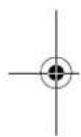
Please make sure that the contacting surface for the magnetic foot is level, clean and rust-free. Remove any varnish or primer.
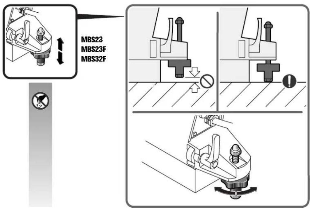
Use the magnetic drill stand only with the magnetic foot switched on.
When working on materials that are not magnetizable, suitable fixation devices, obtainable as accessories from FEIN, e. g. suction plate, vacuum plate or pipe-drilling device must be used.
18
en
When work on steel materials with a material thickness of less than 12 mm, the workpiece must be reinforced with an additional steel plate in order to guarantee the magnetic holding power.
Connect the drive motor only to the socket outlet on the backside of the magnetic drill stand.
The magnetic foot is monitored by means of a power sensor. If the magnetic foot is defective, the drive motor will not start.
Remove the application tool from the drill hole only while the motor is running.
Should the application tool become stuck in the material, stop the drive motor and remove the application tool by carefully turning it anticlockwise.
After each drilling run, remove the chippings and, if required, the drilled out core.
Do not touch the chippings with your bare hand. Always use a chip hook.
When changing the application tool, pay attention not to damage its cutting edges.
When core drilling layered material, remove the core and the chippings after drilling each layer.
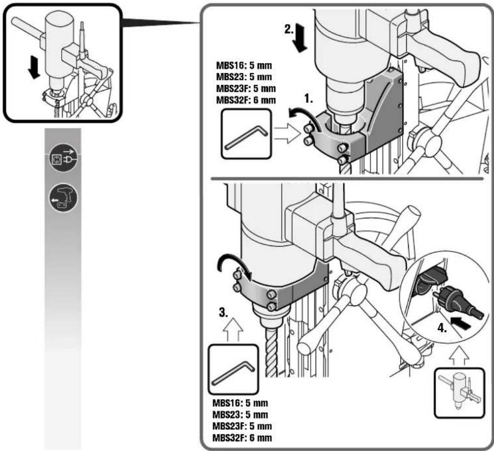
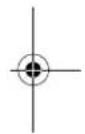
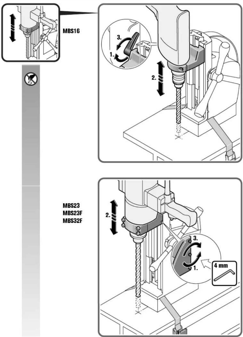
With a tool inserted, the drive motor may not move downward by itself; retighten the hexagon nut as required. (see page 11)
When moving the magnetic drill stand with the drive motor mounted, the unit can tip over when the magnet is switched off. If required, make sure that the magnetic drill stand is secured with a lashing strap.
Repair and customer service.
When replacing the power tool's cable is required, have this carried out by FEIN or by an authorized FEIN Service Agent, in order to avoid hazardous situations.
If required, you can change the following parts yourself:
Application tools, chipping protector, capstan handle with handle levers, holder for drive motor
Warranty and liability.
The warranty for the product is valid in accordance with the legal regulations in the country where it is marketed. In addition, FEIN also provides a guarantee in accordance with the FEIN manufacturer's warranty declaration.
The delivery scope of your power tool may include only a part of the accessories described or shown in this instruction manual.
Declaration of conformity.
FEIN declares itself solely responsible for this product conforming with the relevant provisions given on the last page of this Instruction Manual.
Environmental protection, disposal.
Packaging, worn out power tools and accessories should be sorted for environment-friendly recycling.
Miljøvern, deponering.


Brand : Fein
Model : MBS 32 F
Category : Drill