ESA850 - Brush cutter HUSQVARNA - Free user manual and instructions
Find the device manual for free ESA850 HUSQVARNA in PDF.

User questions about ESA850 HUSQVARNA
0 question about this device. Answer the ones you know or ask your own.
Ask a new question about this device
Download the instructions for your Brush cutter in PDF format for free! Find your manual ESA850 - HUSQVARNA and take your electronic device back in hand. On this page are published all the documents necessary for the use of your device. ESA850 by HUSQVARNA.
USER MANUAL ESA850 HUSQVARNA
natural_image
Silhouette of a hand holding a small object, possibly a tool or device, with no visible text or symbols.ECA850, ESA850
EAC

| EN | Operator's manual | 6-12 |
| BG | Ръководство за експлоатация | 13-20 |
| BS | Korisnički priručnik | 21-27 |
| CS | Návod k použití | 28-35 |
| DA | Brugsanvisning | 36-43 |
| DE | Bedienungsanweisung | 44-51 |
| EL | Однгієх хрніснє | 52-59 |
| ES | Manual de usuario | 60-67 |
| ES-MX | Manual del usuario | 68-75 |
| ET | Kasutusjuhend | 76-82 |
| FI | Käyttöohje | 83-89 |
| FR | Manuel d'utilisation | 90-97 |
| FR-CA | Manuel d'utilisation | 98-105 |
| HR | Priručnik za korištenje | 106-112 |
| HU | Használati utasítás | 113-120 |
| IT | Manuale dell'operatore | 121-128 |
| LT | Operatoriaus vadovas | 129-135 |
| LV | Lietošanas pamácība | 136-143 |
| NL | Gebruiksaanwijzing | 144-151 |
| NO | Bruksanvisning | 152-158 |
| PL | Instrukcja obsługi | 159-166 |
| PT | Manual do utilizador | 167-174 |
| PT-BR | Manual do operador | 175-182 |
| RO | Instructiuni de utilizare | 183-190 |
| RU | Руководство по эксплуатации | 191-199 |
| SK | Návod na obsluhu | 200-207 |
| SL | Navodila za uporabo | 208-214 |
| SR | Priručnik za rukovaoca | 215-221 |
| SV | Bruksanvisning | 222-228 |
| TR | Kullanım kılavuzu | 229-235 |
| UK | Посібник користувача | 236-243 |
| ZH | 操作手册 | 244-250 |
1
ECA 850
text_image
Technical diagram of a mechanical device with numbered components for identification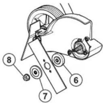
text_image
Technical diagram of a mechanical device with numbered components labeled 6, 7, and 8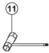
ESA 850
text_image
Technical diagram of a mechanical assembly with numbered components for identification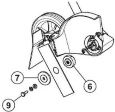
text_image
Technical diagram of a mechanical assembly with numbered parts, likely for assembly or maintenance instructions.
2

3

4

5

6

7

8
9

10

11
12
13

14
15

natural_image
Illustration of a person in protective gear using a manual lawn tool near a tree (no text or symbols)16
natural_image
Line drawing of a hand gripping a cable or wire (no text or symbols)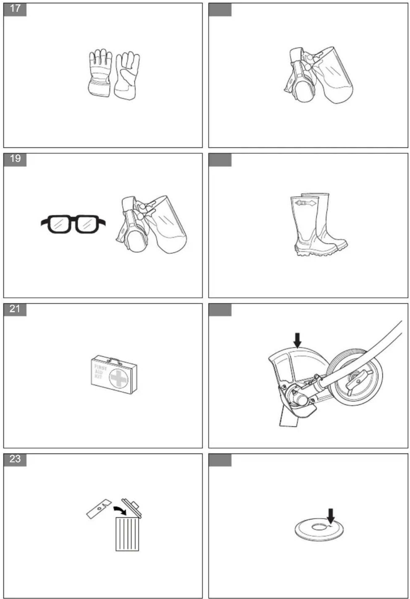
natural_image
Simple line drawing of a nut with a curved arrow indicating rotation (no text or symbols)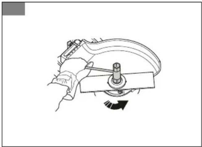
natural_image
Technical line drawing of a mechanical assembly with no visible text or symbols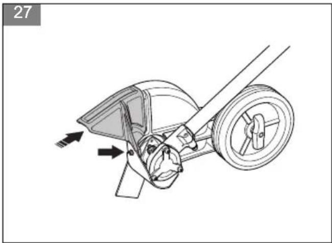
natural_image
Technical line drawing of a mechanical assembly with directional arrows indicating motion (no text or symbols)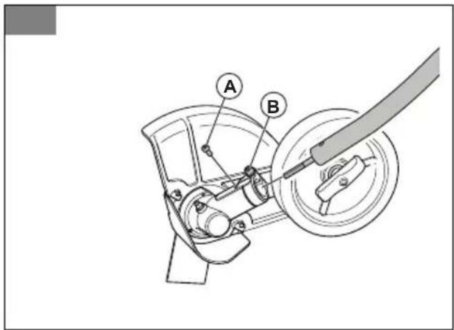
text_image
Technical diagram of a mechanical device with labeled parts A and B, showing internal components and assembly.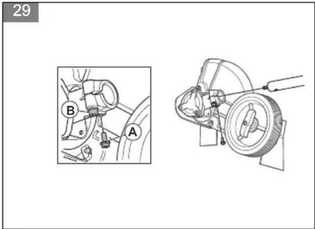
text_image
29 B A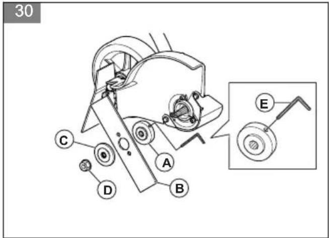
text_image
30 C D A B E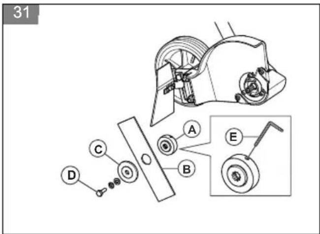
text_image
31 A B C D E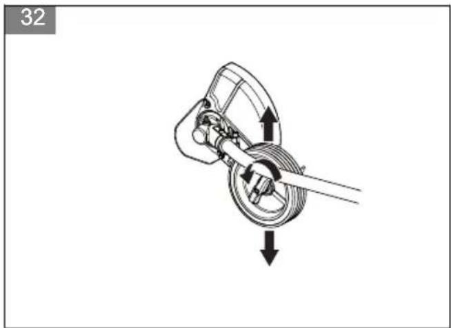
natural_image
Mechanical diagram showing a rotating component with directional arrows indicating motion (no text or symbols)33
natural_image
Mechanical diagram showing a rotating car with directional arrows indicating motion (no text or labels)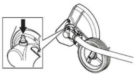
natural_image
Mechanical assembly diagram showing a hand operating a wheel with a separate inset view of a mechanical component (no text or symbols present)35
natural_image
Mechanical assembly diagram showing a wheel and gear assembly with a close-up inset of the component (no text or symbols)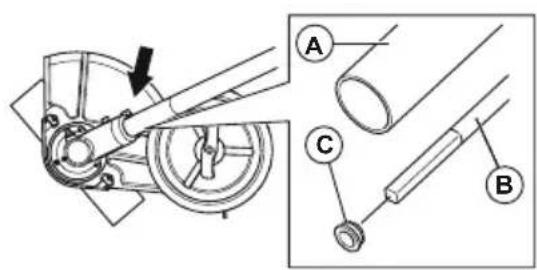
text_image
Technical diagram showing mechanical assembly with labeled parts A, B, and C, including a directional arrow indicating motion.Contents
Introduction......6
Safety....7
Assembly....9
Maintenance.... 10
Technical data.... 10
Contents of the EC declaration of conformity.... 12
Introduction
Product description
We have a policy of continuous product development and therefore reserve the right to modify the design and appearance of the products without prior notice.
Note: This manual cover both gasoline operated and battery operated power units.
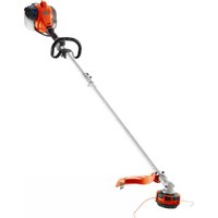
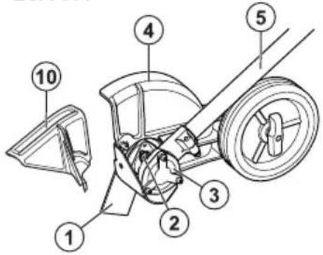
Cutting attachment overview
(Fig. 1)
- Blade
- Grease filler cap, bevel gear
- Bevel gear
- Cutting attachment guard
- Shaft
- Drive disc
- Support flange
- Locknut
- Blade bolt
- Front guard, for battery power unit.
- Combination wrench
- Locking pin
- Operator's manual
Symbols on the cutting attachment
(Fig. 2) Careless or incorrect use of this attachment can result in serious or fatal injury to the operator or others.
(Fig. 3) Please read the operator's manual carefully and make sure you understand the instructions before using the attachment.
(Fig. 4) Please read the operator's manual carefully and make sure you understand the instructions before using the attachment.
(Fig. 5) Always wear approved hearing protection and protective goggles or a visor. A
Intended use

WARNING: Use this attachment only with products that it is intended for. Refer to the accessory chapter in the operator's manual of your product.
Use the attachment for edging lawns only.
breathing mask should be used when there is a risk of dust.
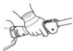
(Fig. 6) Always wear approved protective gloves.
(Fig. 7) Wear sturdy, non-slip boots.
(Fig. 8) Rotating blade. Keep hands and feet clear. The arrow indicates the direction of rotation.
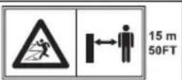
(Fig. 9) Watch out for thrown objects and ricochets.
(Fig. 10) The blade continues to rotate even after the engine/motor has stopped.
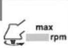
(Fig. 11) Maximum speed of the output shaft.
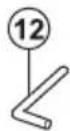
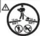
(Fig. 12) Keep a minimum of 15 m / 50 ft distance to persons and animals during operation of the product.
(Fig. 14) The operator must ensure that no people or animals come closer than 15 metres. When several operators are working at the same site a safety distance of at least 15 metres must be in effect. The attachment can forcibly throw objects that can bounce back. This can result in serious eye injuries if the recommended safety equipment is not used.
(Fig. 13) The product agrees with the applicable EC directives.
Note: Other symbols/decals on the attachment refer to special certification requirements for certain markets.
Safety
Safety definitions
Warnings, cautions and notes are used to point out specially important parts of the operator's manual.

WARNING: Used if there is a risk of injury or death for the operator or bystanders if the instructions in the manual are not obeyed.

CAUTION: Used if there is a risk of damage to the product and/or the attachment, other materials or the adjacent area if the instructions in the manual are not obeyed.
Note: Used to give more information that is necessary in a given situation.
General safety instructions

WARNING: Read the safety instructions that follow before you use the attachment.
- Please read the operator's manual carefully and make sure you understand the instructions before using the attachment.
• These instructions supplement the instructions that were included with the product. For other procedures, please refer to the operating instructions for the product. - Under no circumstances may the design of the attachment be modified without the permission of the manufacturer. Do not use an attachment that appears to have been modified by others and always use original accessories. Non-authorized modifications and/or accessories can result in serious personal injury or the death of the operator or others.
Safety instructions for operation

WARNING: Read the safety instructions that follow before you use the product.
- Do not let children to use the product.
- Do not let anyone else to use the product without first made sure that they have understood the contents of the operator's manual.
- Keep unauthorized persons at a distance. Children, animals, onlookers and helpers should be kept outside the safety zone of 15 m (50 ft) while you work. Stop the product immediately if anyone go near.
- Make sure you can move and stand safely. Check the area around you for possible obstacles (roots, rocks, branches, ditches, etc.) in case you must move suddenly. Take great care when you work on sloping ground.
(Fig. 15)
- Examine the work area. Remove all loose objects, such as stones, broken glass, nails, steel wire, string, etc. that could be thrown out or become wrapped around the blades or cutting attachment guard.
- Look out for thrown objects. Always wear approved eye protection. Do not lean over the cutting attachment guard. Stones, rubbish, etc. can be thrown up into the eyes causing blindness or serious injury.
- Do not use the product in bad weather, such as dense fog, heavy rain, strong wind, intense cold, etc.
- Do not use the product unless you are able to call for help in the event of an accident.
- The engine/motor must be switched off before moving.
- Do not put the product down with the engine/motor running unless you have it in clear view.
• Always use both hands to hold the product. Hold the product at the side of your body. - Use your right hand to control the throttle trigger/power trigger.
(Fig. 16)
- Listen out for warning signals or shouts when you wear hearing protection. Always remove your hearing protection as soon as the engine/motor stops.
- If the cutting attachment is attached to a battery power unit, the front guard must be installed. Refer to To install the front guard, battery power units on page 9.
- Make sure that your hands and feet do not come near the cutting attachment when the engine/motor is on.
- When the engine/motor is switched off, keep your hands and feet away from the cutting attachment until it has stopped fully.
- Always keep the cutting attachment near the ground.
• Always do edging at full throttle/speed. - Always slow the engine/motor to idle speed after each work operation. Long periods at full throttle/speed without any load on the engine/motor (i.e without the resistance that the cutting attachment exerts on the engine/motor when you are using the product) can lead to serious engine/motor damage.
-
Be especially careful when you pull the edger towards you during work.
-
If any object is hit or if vibrations occur stop the product immediately. If you have a gasoline operated product, remove the spark plug cap from the spark plug. If you have a battery operated product, remove the battery. Check that the product is not damaged. Repair any damage.
- Sometimes grass or stones can get trapped in the cutting attachment guard and cutting attachment. Always stop the engine/motor before you clean it.
Personal protective equipment

WARNING: You must use approved personal protective equipment whenever you use the product. Personal protective equipment cannot eliminate the risk of injury but it will reduce the degree of injury if an accident does happen. Ask your dealer for help in choosing the right equipment. Please read the operator's manual carefully and make sure you understand the instructions before using the product.
- Gloves should be worn when necessary.
(Fig. 17) - Wear hearing protection that provides adequate noise reduction.

WARNING: Listen out for warning signals or shouts when you are wearing hearing protection. Always remove your hearing protection as soon as the engine/motor stops.

WARNING: Long-term exposure to noise can result in permanent hearing impairment. So always use approved hearing protection.
(Fig. 18)
- Always wear approved eye protection. If you use a visor then you must also wear approved protective goggles. Approved protective goggles must comply with the ANSI Z87.1 standard in the USA or EN 166 in EU countries. Blows from branches or objects that are thrown can damage the eyes.
(Fig. 19) - Wear sturdy, non-slip boots.
(Fig. 20)
• Always wear heavy, long pants, boots, gloves, and a long-sleeve shirt. To reduce the risk of injury associated with objects being drawn into rotating parts, do not wear loose clothing, scarves, jewelry, etc. Secure hair so it is above shoulder level. - A breathing mask should be used when there is a risk of dust.
• Always have a first aid kit nearby.
(Fig. 21)
Safety devices on the attachment

WARNING: Read the warning instructions that follow before you use the attachment.
This section contains the attachment's safety features, its purpose and how checks and maintenance should be carried out to ensure that it operates correctly. See instructions under the heading Cutting attachment overview on page 6 to find where these parts are located on your attachment.
The life span of the attachment can be reduced and the risk of accidents can increase if attachment maintenance is not carried out correctly and if service and/or repairs are not carried out professionally. If you need further information please contact your nearest servicing dealer.

WARNING: Never use an attachment with defective safety components. The attachment's safety equipment must be inspected and maintained as described in this section. If your attachment fails any of these checks, contact your service agent to get it repaired.

WARNING: All servicing and repair work on the product requires special training. This is especially true of the product's safety equipment. If your product fails any of the checks described below you must contact your service agent. When you buy any of our products we guarantee the availability of professional repairs and service. If the retailer who sells your product is not a servicing dealer, ask him for the address of your nearest service agent.
To check the cutting attachment guard

WARNING: Do not use a cutting attachment without an approved cutting attachment guard. If an incorrect or damaged cutting attachment guard is installed this can cause injury.

WARNING: If the cutting attachment is attached to a battery power unit, make sure that the front guard is installed.
- Make sure that the cutting attachment guard and front guard is not damaged. Replace the cutting attachment guard and front guard if it is damaged. (Fig. 22)
- Only use original spare parts.
To check the blade
The blade is designed and manufactured to withstand the loads that edging of a lawn involves.
- Check the blade for damage or cracks. A damaged blade should always be replaced. (Fig. 23)
To check the support flange
- Check that the support flange is not cracked due to fatigue or due to being tightened too much. Discard the support flange if it is cracked. (Fig. 24)
To check the locknut

CAUTION: The nylon lining inside the locknut must not be so worn that you can turn it by hand. The lining should offer a resistance of minimum 1.5 Nm / 13 in-lb. The locknut must be replaced after it has been put on approximately 10 times.

CAUTION: The locknut has a left-hand thread. To tighten the locknut to much can cause damage to the threads.
The locknut secures the cutting attachment on the output shaft. Protect your hand from injury when assembling, use the cutting attachment guard as protection when tightening with a socket wrench.
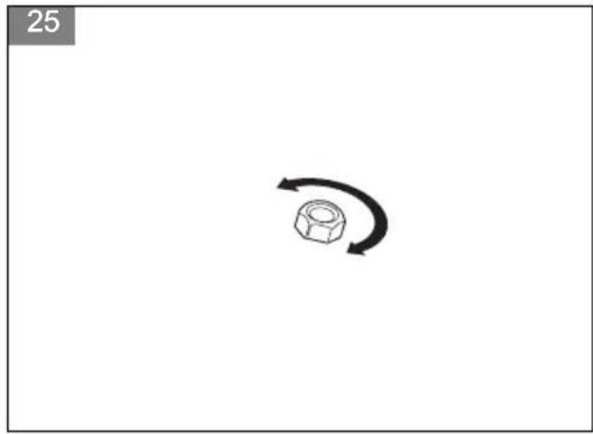
- When fitting, tighten the locknut in the opposite direction to the direction of rotation of the cutting attachment. To remove it, undo the locknut in the same direction as the cutting attachment rotates. (Fig. 25)
- Tighten the locknut using a socket wrench to 15-20 Nm / 11-20 ft-lb. (Fig. 26)
Safety instructions for maintenance

WARNING: Read the safety instructions that follow before you use the product.
- Always stop the engine/motor before you do work on the cutting attachment. The blade continues to move after the throttle/power trigger is released. If you have a gasoline operated product, remove the spark plug cap from the spark plug. If you have a battery operated product, remove the battery. Make sure that the cutting attachment has stopped fully before you do work on it.
• Always wear heavy duty gloves when you repair the cutting attachment. This is very sharp and can easily cause cuts. - Use only original spare parts for repairs.
- Keep the product away from children
Assembly
To install the front guard, battery power units
- Install the front guard on the front of the cutting attachment guard. (Fig. 27)
- Attach the bolt and tighten it.
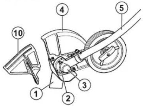
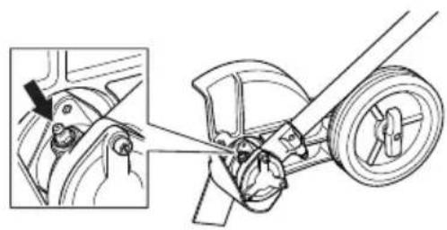
To assemble the bevel gear
- Insert the driveshaft into the bevel gearbox housing. Turn the cutting attachment so that the shaft engages in the bevel gear.
- Attach the bevel gear box to the shaft tube aligning the positioning holes.
- Fasten the screw (A), then fasten the clamp bolt (B) firmly, 6-8 Nm / 53-70 in-lb.
a) For model ECA850: (Fig. 28)
b) For model ESA850: (Fig. 29)
To assemble the cutting attachment

WARNING: Never use a cutting attachment without without an approved cutting attachment guard. If an incorrect or faulty cutting attachment guard is fitted this can cause serious personal injury.
- Fit the drive disc (A) on the output shaft. Make sure that the edge of the drive disc, that fits in the hole of the blade, is facing outwards.
a) For model ECA850: (Fig. 30)
b) For model ESA850: (Fig. 31) - Lock the blade rotation by inserting the locking pin (E) in the hole on the drive disc.
- Fit the blade (B) on the drive disc.
- Fit the support flange (C). The support flange must be fitted so that its outer edge presses against the blade.
- Fit the locknut / blade mounting bolt (D). The locknut / blade mounting bolt has a left-hand thread. Tighten the locknut / blade mounting bolt to a torque of 15-20 Nm / 12-15 ft-lb.
- Remove the locking pin.
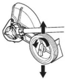
To adjust the cutting depth of the cutting attachment
The cutting depth of the cutting attachment must be adjusted before starting work.
- Loosen the wing nut.
a) For model ECA850: (Fig. 32)
Maintenance
Introduction
Below you will find some general maintenance instructions. If you need further information please contact your service workshop.
To perform daily maintenance
- Check that the blade does not rotate when the throttle/power trigger is released.
- Check that the cutting attachment guard is undamaged and not cracked. Replace the cutting attachment guard if it has been exposed to impact or is cracked.
- Check that the blade is not damaged and not cracked. Replace the blade if necessary.
- Check that the support flage is not damaged.
- Check that the locknut is tight.
To perform weekly maintenance
- Check that the bevel gear is filled to 34 with grease. Fill if necessary using special grease.
To check the bevel gear
The bevel gear is filled with the right quantity of grease at the factory. The grease in the bevel gear does not normally need to be changed except if repairs are carried out.
- Before using the product check that the bevel gear is filled to 34 with grease. Fill if necessary using special grease.
a) For model ECA850: (Fig. 34)
b) For model ESA850: (Fig. 35)
To lubricate the flexible drive shaft
Only for model ECA850.
- Loosen the 2 screws on the bevel gear.
- Remove the bevel gear.
- Take a firm grip on the hollow shaft (A) and remove the flexible drive shaft (B) from the opposite end of the gear box. (Fig. 36)
Note: The bushing (C) will fall off when you remove the flexible driveshaft. Make sure that you do not lose it. Put the bushing safely aside.
-
Lubricate the entire length of the flexible drive shaft.
-
Reinsert the flexible driveshaft in the hollow shaft. Turn the flexible driveshaft while inserting it so that it correctly engages in the bevel gear.
-
Attach the bushing on the flexible drive shaft.
-
Attach the bevel gear on the hollow drive shaft and tighten the 2 screws.
Technical data
Technical data for gasoline operated products
| ECA850 ESA850 | ||
| Weight | ||
| Weight, kg 1.6 1.6 | ||
| Dimensions | ||
| Blade length, mm 195 195 | ||
| Center hole, blade, mm 25.4 25.4 | ||
| Speed | ||
| Speed, blade, rpm 7140 7140 | ||
| Noise emissions | ||
| Sound power level according to ISO 22868, measured, dB (A) 114 114 | ||
| Sound levels ^1 | ||
| Sound pressure level at the operator's ear, measured according to ISO 11789 | ||
| Equipped with approved accessory (original), dB (A) 98 98 | ||
| Vibrations ^2 | ||
| Vibration levels at handles, measured according to ISO 22867 | ||
| Equipped with approved accessory (original), front/rear, m/s ^2 6.7/12 6 | 7/12 | |
Technical data for battery operated products
| ECA850 ESA850 | ||
| Weight | ||
| Weight, kg 1.6 1.6 | ||
| Dimensions | ||
| Blade length, mm 195 195 | ||
| Center hole, blade, mm 25.4 25.4 | ||
| Speed | ||
| Speed, blade, rpm 8354 8354 | ||
| Noise emissions ^3 | ||
| Sound power level, measured, dB (A) 95 90 | ||
| Sound levels ^4 | ||
| Equivalent sound pressure level at the operator's ear, measured according to ISO 26868 | ||
| Equipped with approved accessory (original), dB (A) 81 78 | ||
| Vibrations ^5 | ||
| Vibration levels at handles, measured according to EN 62841-1 | ||
| Equipped with approved accessory (original), left/right, m/s ^2 5.5/2.2 1.3/1.4 | ||
Contents of the EC declaration of conformity
Contents of the EC declaration of conformity
We, Husqvarna AB, SE 561 82 Huskvarna, SWEDEN, declare under our sole responsibility that the represented product:
| Description Edger attachment | |
| Brand Husqvarna | |
| Platform / Type / Model Platform | UEDA, representing models ECA850, ESA850. |
| Batch Serial number dating | 2018 and onwards. |
complies fully with the following EU directives and regulations:
| Directive/Regulation | Description |
| 2006/42/EC “relating to machinery” | |
| 2000/14/EC “relating to outdoor noise” | |
| 2014/30/EU "relating to electromagnetic compatibility" | |
| 2011/65/EU “restriction of use of certain hazardous substances” |
Harmonized standards and/or technical specifications applied are as follows: EN ISO 12100:2010, ISO 11789:1999, ISO 14982:2009
Following standards have been applied for battery products: IEC 62841-1:2014, EN 11789:1999, EN 55014-1:2006+A1+A2, EN 55014-2:2015
TÜV Rheinland N.A. has carried out a voluntary examination on behalf of Husqvqrna AB, providing Certificate of Conformity AK72140365.
In accordance with annex V, the declared sound values are:
| Petrol | Battery | |
| Measured sound power level, dB(A) | 108 92 | |
| Guaranteed sound power level, dB(A) | 114 95 |
The supplied product conforms to the example that underwent examination.
On behalf of Huskvarna AB, SE 561 82 Huskvarna, SWEDEN, 2019-05-29

text_image
Pei GusleptenPer Gustafsson
Responsible for technical documentation
Содержание
Въведение.... 13
Безопасност....14
Монтаж....17
Поддръжка....17
Kun for model ECA850.
text_image
Pe GustefPer Gustafsson
(Joon. 7) Kandke tugevaid, mittelibisevaid saapaid.
Len pre model ECA850.
- Uvočnite 2 skrutky na kuželovom prevode.
- Demontujte kuželový prevod.
- Pevne uchopte dutý hriadel (A) a vyberte ohybný hnací hriadel (B) na opačnom konci prevodovky. (Obr. 36)
2006/42/ES "o strojih"