131RB - Brush cutter HUSQVARNA - Free user manual and instructions
Find the device manual for free 131RB HUSQVARNA in PDF.

| Product Type | Brush cutter |
| Brand | Husqvarna |
| Model | 131RB |
| Engine Displacement | 27.6 cc |
| Power Output | 1.1 kW |
| Weight | 6.5 kg |
| Fuel Type | Mixed gasoline (2-stroke, 50:1 ratio) |
| Fuel Tank Capacity | 0.5 L |
| Cutting Attachment | Trimmer head or grass blade (26-28 cm) |
| Shaft Type | Straight |
| Handle Type | Bike handle |
| Starter System | Easy Start (Smart Start) |
| Safety Features | Throttle lock, stop switch, guard |
| Emission Standards | EPA, CE |
| Maintenance Tips | Clean air filter, replace spark plug, sharpen blade |
| Spare Parts Availability | Yes, through Husqvarna dealers |
| Vibration Level | 4.2 m/s² (handle) |
| Sound Pressure Level | 92 dB(A) |
| Cutting Capacity | Up to 1.5 cm thick stems |
Frequently Asked Questions - 131RB HUSQVARNA
User questions about 131RB HUSQVARNA
0 question about this device. Answer the ones you know or ask your own.
Ask a new question about this device
Download the instructions for your Brush cutter in PDF format for free! Find your manual 131RB - HUSQVARNA and take your electronic device back in hand. On this page are published all the documents necessary for the use of your device. 131RB by HUSQVARNA.
USER MANUAL 131RB HUSQVARNA
natural_image
Three black-and-white icons: warning triangle, open book, and trash bin (no text or symbols)Husqvarna®
natural_image
Silhouette of a selfie stick with a hand and wrist, no text or symbols present131RB
EN Operator's manual 2-21
Contents
INTRODUCTION....2
SAFETY....4
ASSEMBLY....9
OPERATION....12
MAINTENANCE....16
TROUBLESHOOTING....18
TRANSPORTATION AND STORAGE.... 19
TECHNICAL DATA....19
ACCESSORIES....20
INTRODUCTION
Operator's manual
The initial language of this operator's manual is English.
Operator's manuals in other languages are translations
from English.
Product overview
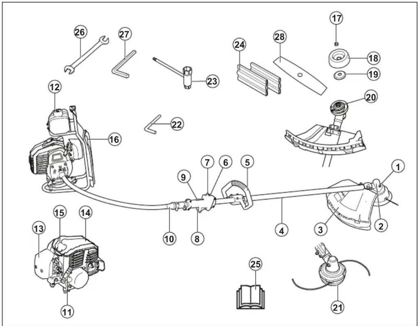
- Grease filler cap, bevel gear
- Bevel gear
- Cutting attachment guard
-
Shaft
-
Loop handle
- Start throttle button
- Stop switch
-
Throttle trigger
-
Throttle trigger lockout
-
Flexible drive shaft coupling
-
Starter handle
-
Fuel tank
-
Air filter cover
-
Cylinder cover
-
Spark plug cap and spark plug
-
Harness
-
Locking nut
-
Support cup
-
Support flange
-
Drive disc
-
Trimmer head
-
Locking pin
-
Socket spanner
-
Transport guard
-
Operator's manual
-
Spanner
-
Allen key
-
2-teeth blade
Symbols on the product

WARNING! This product is dangerous. Injury or death can occur to the operator or bystanders if the product is not used carefully and correctly. To prevent injury to the operator or bystanders, read and obey all safety instructions in the operator's manual.

Please read the operator's manual carefully and make sure that you understand the instructions before use.

Use a protective helmet in locations where objects can fall on you. Use approved hearing protection. Use approved eye protection.

Use approved protective gloves.

Use heavy-duty slip-resistant boots.

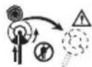
The product can cause objects to eject, which can cause injury.

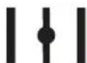
Maximum speed of the output shaft.
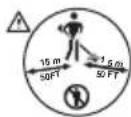
Keep a minimum of 15 m (50 ft) distance to persons and animals during operation of the product.
Risk of blade thrust if the cutting equipment touches an object that it does not immediately cut. The product can cut off body parts. Keep a minimum of 15 m (50 ft) distance to persons and animals during operation of the product.
Air purge bulb.

The direction to close the choke.
The direction to open the choke.
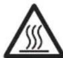
Keep all parts of your body away from the hot surfaces.
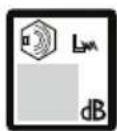
Noise emission to the environment refer to the European Community's Directive. The emission of the product is specified in the Technical data chapter and on the label.
Note: Other symbols/decals on the product refer to certification requirements for other commercial areas.
Product liability
As referred to in the product liability laws, we are not liable for damages that our product causes if:
• the product is incorrectly repaired.
• the product is repaired with parts that are not from the manufacturer or not approved by the manufacturer.
• the product has an accessory that is not from the manufacturer or not approved by the manufacturer.
- the product is not repaired at an approved service center or by an approved authority.
SAFETY
Safety definitions
The definitions below give the level of severity for each signal word.

WARNING: Injury to persons.

CAUTION: Damage to the product.
Note: This information makes the product easier to use.
General safety instructions
- Use the product correctly. Injury or death is a possible result of incorrect use. Only use the product for the tasks found in this manual. Do not use the product for other tasks.
- Obey the instructions in this manual. Obey the safety symbols and the safety instructions. If the operator does not obey the instructions and the symbols, injury, damage or death is a possible result.
- Do not discard this manual. Use the instructions to assemble, to operate and to keep your product in good condition. Use the instructions for correct installation of attachments and accessories. Only use approved attachments and accessories.
- Do not use a damaged product. Obey the maintenance schedule. Only do the maintenance work that you find an instruction about in this manual. An approved service center must do all other maintenance work.
- This manual cannot include all situations that can occur when you use the product. Be careful and use your common sense. Do not operate the product or do maintenance on the product if you are not sure about of the situation. Speak to a product expert, your dealer, service agent or approved service center for information.
- Disconnect the spark plug cable before you assemble the product, put the product into storage or do maintenance.
- Do not use the product if it is changed from its initial specification. Do not change a part of the product without approval from the manufacturer. Only use parts approved by the manufacturer. Injury or death is a possible result of incorrect maintenance.
- Do not breathe in the fumes from the engine. Long-term inhalation of the engine's exhaust fumes is a health risk.
- Do not start the product indoors or near flammable material. The exhaust fumes are hot and can contain a spark which can start a fire. Not sufficient airflow
can cause injury or death because of asphyxiation or carbon monoxide.
- When you use this product the engine makes an electromagnetic field. The electromagnetic field can cause damage to medical implants. Speak to your physician and medical implant manufacturer before you operate the product.
- Do not let a child operate the product. Do not let a person without knowledge of the instructions operate the product.
- Make sure that you always monitor a person, with decreased physical capacity or mental capacity, that uses the product. A responsible adult must be there at all times.
- Lock the product in an area that children and unapproved persons cannot access.
- The product can eject objects and cause injuries. Obey the safety instructions to decrease the risk of injury or death.
- Do not go away from the product when the engine is on.
- The operator of the product is responsible if an accident occurs.
- Make sure that parts are not damaged before you use the product.
- Make sure that you are at minimum 15 m (50 ft) away from other persons or animals before you use the product. Make sure that persons in the adjacent area know that you will use the product.
- Refer to national or local laws. They can prevent or decrease the operation of the product in some conditions.
- Do not use the product if you are fatigued or influenced by alcohol, drugs or medicine. They can have effects on your vision, alertness, coordination or judgment.
Safety instructions for operation
- Make sure the product is fully assembled before you use it.
- Before a start, move the product 3 m (10 ft) away from the position where you filled the fuel tank. Put the product on a flat surface. Make sure that the cutting attachment does not touch the ground or other objects.
- The product can cause objects to eject, which can cause damage to the eyes. Always use an approved eye protection when you operate the product.
- Be careful, a child can come near the product without your knowledge during operation.
- Do not operate the product if there are persons in the work area. Stop the product if a person goes into the work area.
-
Make sure that you are always in control of the product.
-
Do not use the product if you cannot receive aid if an accident occurs. Always make sure others know you will operate the product before you start to operate the product.
- Do not turn with the product before you make sure that no persons or animals are in the safety area.
- Remove all unwanted materials from the work area before you start. If the cutting attachment hits an object, the object can eject and cause injury or damage. Unwanted material can wind around the cutting attachment and cause damage.
- Do not use the product in bad weather (fog, rain, strong winds, risk of lightning or other weather conditions.). Dangerous conditions (such as slippery surfaces) can occur because of bad weather.
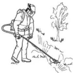
• Make sure that you can move freely and work in a stable position.
natural_image
Line drawing of a person in protective gear using a long tool to clean or spray outdoors (no text or symbols)• Make sure that you cannot fall when you use the product. Do not tilt when you operate the product.
• Always hold the product with your two hands. Hold the product on the right side of your body.
natural_image
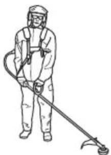
Line drawing of a person in full protective suit using a manual power tool (no text or symbols)- Operate the product with the cutting attachment below your waist.
- If the choke control is in the choke position when the engine starts, the cutting attachment starts to turn.
- Do not touch the bevel gear after the engine stops. The bevel gear is hot after the engine stops. Hot areas can cause injury.
- Stop the engine before you move the product.
- Do not put down the product with the engine on.
- Before you remove the unwanted materials from the product, stop the engine and wait until the cutting attachment stops. Let the cutting attachment stop before you or an aid remove the cut material.
Personal protective equipment
• Always use correct personal protective equipment when you operate the product. The personal
protective equipment does not erase the risk of injury. The personal protective equipment decreases the grade of injury if an accident occurs.
• Always use an approved eye protection while you operate the product.
- Do not operate the product with bare feet or with open shoes. Always use heavy-duty slip-resistant boots.
- Use heavy, long pants.
- If it is necessary, use approved protective gloves.
- Use a helmet if it is possible that objects fall on your head.
• Always use approved ear protection while you operate the product. Noise for a long period can cause noise-induced hearing loss.
• Make sure that you have a first aid kit near.
Protective devices on the product
• Make sure that you regularly do the maintenance to the product.
• The life of the product increases.
• The risk of accidents decreases.
Let an approved dealer or an approved service center regularly examine the product to do adjustments or repairs.
- Do not use a product with damaged protective equipment. If the product is damaged, speak to an approved service center.
Throttle trigger lockout
The throttle trigger lockout locks the throttle trigger.
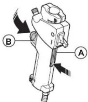
Push the throttle trigger lockout (A) to release the throttle trigger (B). When you release the handle, the throttle trigger lockout and the throttle trigger go back to their initial positions.
- Make sure that the throttle trigger (B) is locked at idle when you release the throttle trigger lockout (A).
- Push the throttle trigger lockout (A) and make sure that it goes back to its initial position when you release it.
- Push the throttle trigger (B) and make sure that it goes back to its initial position when you release it.
Start the engine, and then apply full throttle. Release the throttle trigger and examine if the cutting attachment stops. If the cutting attachment turns with the throttle in
the idle position, examine the idle adjustment screw of the carburetor.
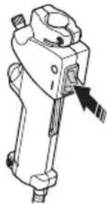
Stop switch
Start the engine. Make sure that the engine stops when you move the stop switch to the stop position.
natural_image
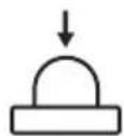
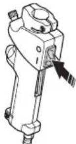
Technical line drawing of a mechanical device with a black arrow pointing to a component (no text or symbols present)Cutting attachment guard
The cutting attachment guard prevents a loose object to eject in the direction of the operator. Examine the cutting attachment guard for damage and replace if it is damaged. Only use the approved guard for the cutting attachment.
natural_image
Line drawing of a tool interacting with a mechanical component (no text or symbols)Vibration damping system

WARNING: Overexposure to vibration can lead to circulatory damage or nerve damage in people who have impaired circulation. Contact your doctor if you experience symptoms of overexposure to vibration. Such symptoms include numbness, loss of feeling, tingling, pricking, pain, loss of strength, changes in skin color or condition. These symptoms normally appear in the fingers, hands, shoulder or wrists. These symptoms may be increased in cold temperatures.
- Your product has a vibration damping system to reduce vibration and make operation easier.
- Incorrect wound trimmer line or blunt or incorrect cutting attachment increases the level of vibration.
natural_image
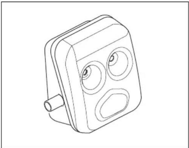
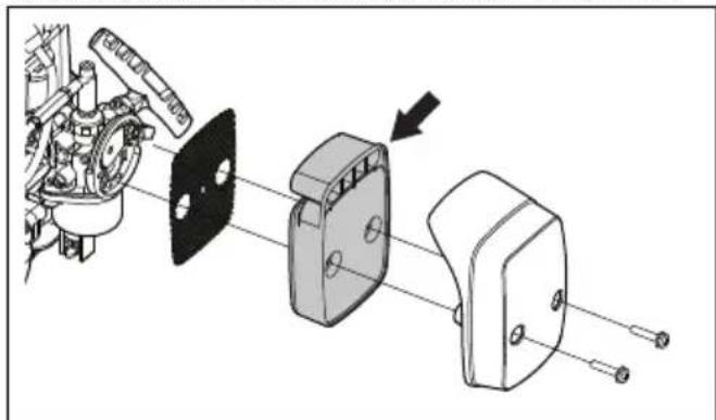
Technical line drawing of a mechanical pump assembly (no text or symbols)Muffler
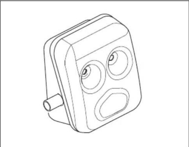
natural_image
Line drawing of a rectangular electronic device with three circular ports and a cylindrical shaft (no text or symbols)The muffler keeps the noise level to a minimum and keeps exhaust fumes away from the operator.
- Do not use an engine with a damaged muffler. A damaged muffler increases the noise level and the risk of fire. Keep a fire extinguisher near.
- Examine regularly that the muffler is attached to the product.
- Do not touch the engine or the muffler when then engine is on. Do not touch the engine or the muffler for a while after the engine stops. Hot surfaces can cause injuries.
- A hot muffler can cause a fire. Be careful, if you use the product near flammable liquids or fumes.
- Do not touch the parts in the muffler, if the muffler is damaged. The parts can contain some carcinogenic chemicals.
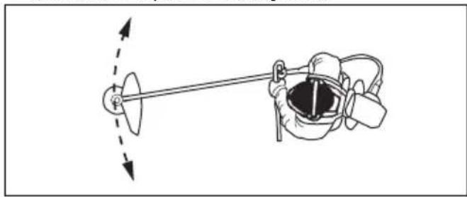
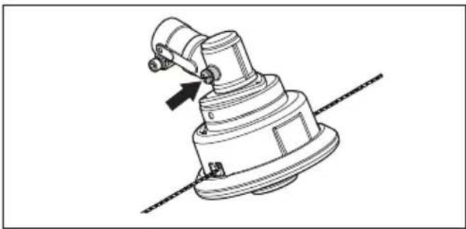
To attach and remove the locknut

WARNING: Stop the engine, use protective gloves and be careful around the sharp edges of the cutting attachment.
A locknut is used to attach some types of cutting attachments. The locknut has a left thread.
• To attach, tighten the locknut in the opposite direction to the direction of turning of the cutting attachment.
• To remove the locknut, loosen the locknut in the same direction as the cutting attachment rotates.
- To loosen and tighten the locknut, use a socket wrench with a long shaft. The arrow in the picture shows the area where you can operate the socket wrench.
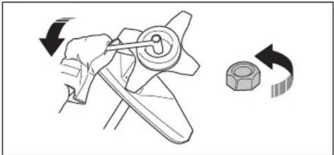
natural_image
Diagram showing a hand operating a propeller with a nut, illustrating the process of rotation (no text or symbols present)
WARNING: When you loosen and tighten the locknut, there is a risk of injury from the blade. You must always make sure that the blade guard prevents injury to your hand when you do this.
Note: Make sure that you can not turn the locknut by hand. Replace the nut if the nylon lining does not have a resistance of a minimum of 1.5 Nm. The locknut must be replaced after it has been put on approximately 10 times.
Cutting equipment
Choose and maintain the cutting equipment to:
- Obtain maximum cutting performance.
- Increase life span of the cutting equipment.
- Follow the checking, maintenance and service instructions for the muffler.
• Always use the recommended guard for the cutting equipment. See Technical data.

WARNING: Only use cutting attachments with the guards we recommend! See the chapter on Technical data. Refer to the instructions for the cutting attachment to check the correct way to load the trimmer line and the correct trimmer line diameter.

WARNING: A faulty cutting attachment may increase the risk of accidents.

WARNING: Always stop the engine before doing any work on the cutting attachment. This continues to rotate even after the throttle has been released. Ensure that the cutting attachment has stopped completely
and disconnect the spark plug cap before you start to work on it.
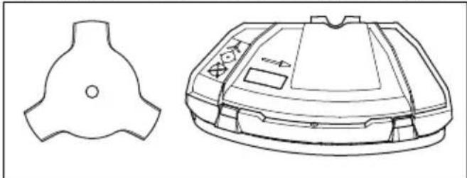
Cutting equipment
- Use the blades and grass knives to cut coarse grass.
natural_image
Technical line drawing of a mechanical component with two views: top shows a three-bladed shape, bottom shows a circular housing with internal components (no text or symbols)- Use the trimmer head to trim grass.
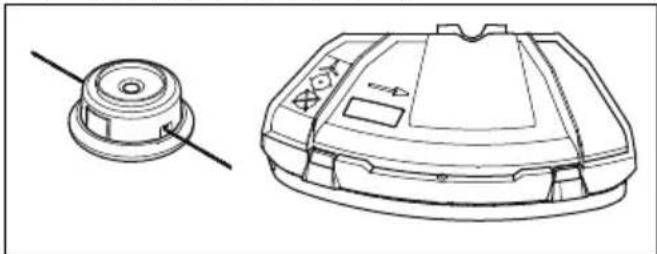
natural_image
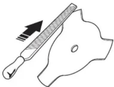
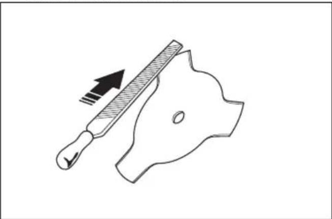
Technical line drawing of a mechanical component with a circular base and a top view (no text or symbols)- An incorrectly sharpened or damaged blade increases the risk of accidents. Keep the teeth of the blade correctly sharpened. Follow the instructions and use the recommended file gauge.
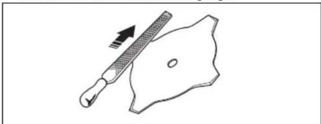
natural_image
Simple line drawing of a grater and shield with an arrow indicating direction (no text or symbols)- Check the cutting attachment for damage or cracks. Replace a damaged cutting attachment.
- Only use cutting attachments with recommended guards. See ACCESSORIES on page 20.
Trimmer head

WARNING: Always make sure the trimmer line is wound tightly and evenly around the drum to prevent harmful vibration.
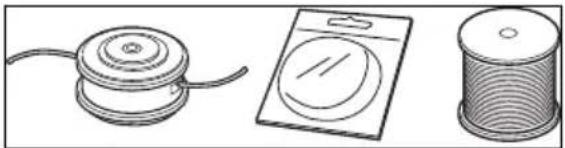
natural_image
Three technical illustrations of mechanical components: a spool, a washer, and a spool (no text or symbols)- Only use recommended trimmer heads and trimmer lines.
- Only use recommended cutting attachments.
- Smaller machines requires small trimmer heads and vice versa.
-
The length of the trimmer line is important. A longer trimmer line requires greater engine power than a shorter trimmer line of the same diameter.
-
Make sure that the cutter on the trimmer guard is intact. This cuts the trimmer line to the correct length.
- Soak the trimmer line in water for a couple of days before use to increase the life length.
Grass blades and grass cutters
- Use the product with an approved grass blade. Do not use a grass blade without proper installation of all required parts. Make sure that the installation is done correctly and that the proper parts are used. Inproper installation may cause the blade to fly off and seriously injure the operator or the bystanders.
- Wear protective gloves when you handle or do maintenance on the blade.
- Use head protection when you operate a product with a grass blade.
- Grass blades and grass cutters are used to cut rough grass.
- A grass blade can cause injury while it continues to spin after the engine is stopped or the throttle trigger is released. Make sure that the grass blade has completely stopped rotating before any maintenance.
- Stop the engine before you do work on the cutting attachment. Make sure the cutting attachment fully stops. Disconnect the lead from the spark plug.
- Only use an approved cutting attachment or a correctly sharpened blade.
- Keep the teeth of the blade correctly sharpened.
natural_image
Diagram of a tool interacting with a mechanical part, showing a handle and blade (no text or symbols)- Do not use a damaged cutting attachment.
- Attach the transport guard to the grass blade when you transport or store the product.
Blade thrust
- A blade thrust is a sudden movement of the product to the side, forward or rearward. A blade thrust occurs when the grass blade hits an object that cannot be cut. In areas where it is not easy to see the material being cut the risk of blade thrust increases.
- When a blade thrust occurs, there is a risk that the product or the operator moves out of position. A blade that moves can hit bystanders and there is a risk of injuries.
- If a blade is bent, has cracks, is broken or damaged, discard the blade.
- Use a sharp blade. The risk of blade thrust increases when a blade is not sharp.
Fuel safety
- Do not start the product if there is fuel or engine oil on the product. Remove the unwanted fuel/oil and let the product dry. Remove unwanted fuel from the product.
- If you spill fuel on your clothing, change clothing immediately.
- Do not get fuel on your body, it can cause injury. If you get fuel on your body, use a soap and water to remove the fuel.
- Do not start the engine if you spill oil or fuel on the product or on your body.
- Do not start the product if the engine has a leak. Examine the engine for leaks regularly.
- Be careful with fuel. Fuel is flammable and the fumes are explosive and can cause injuries or death.
- Do not breathe in the fuel fumes, it can cause injury. Make sure that there is a sufficient airflow.
- Do not smoke near the fuel or the engine.
- Do not put warm objects near the fuel or the engine.
- Do not add the fuel when the engine is on.
- Make sure that the engine is cool before you refuel.
- Before you refuel, open the fuel tank cap slowly and release the pressure carefully.
- Do not add fuel to the engine in an indoor area. Not sufficient airflow can cause injury or death because of asphyxiation or carbon monoxide.
- Tighten the fuel tank cap carefully or a fire can occur.
- Move the product at a minimum of 3 m (10 ft) from the position where you filled the tank before a start.
- Do not put too much fuel in the fuel tank.
- Make sure that a leak cannot occur when you move the product or fuel container.
- Do not put the product or a fuel container where there is an open flame, spark or pilot light. Make sure that the storage area does not contain an open flame.
- Only use approved containers when you move the fuel or put the fuel into storage.
- Empty the fuel tank before long-term storage. Obey the local law on where to dispose fuel.
- Clean the product before long-term storage.
- Remove the spark plug cable before you put the product into storage to make sure that the engine does not start accidentally.
Safety instructions for maintenance
- If you cannot adjust the idle speed to make the cutting attachment stop, speak to your service center. Do not use the product until the product is correctly adjusted or repaired.
ASSEMBLY

WARNING: Read the safety chapter before you assemble the product.
To install the loop handle
- Remove the four screws.
- Put the loop handle on the shaft and put the lower clamp below the shaft.
- Align the lower clamp pin with the correct hole in the shaft and put the pin in the hole.
- Align the hole in the loop handle with the screw hole in the lower clamp.
- Install the screws with nuts and tighten.
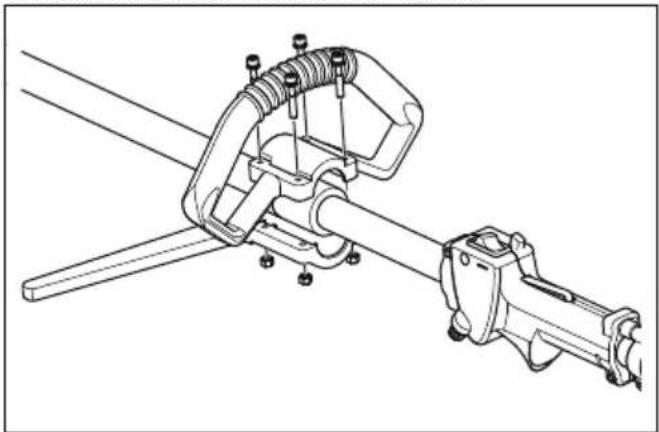
natural_image
Technical line drawing of a mechanical linkage assembly (no text or symbols)To connect the throttle cable and stop switch wires
- Connect the throttle wire to the carburetor connection and close the holder.
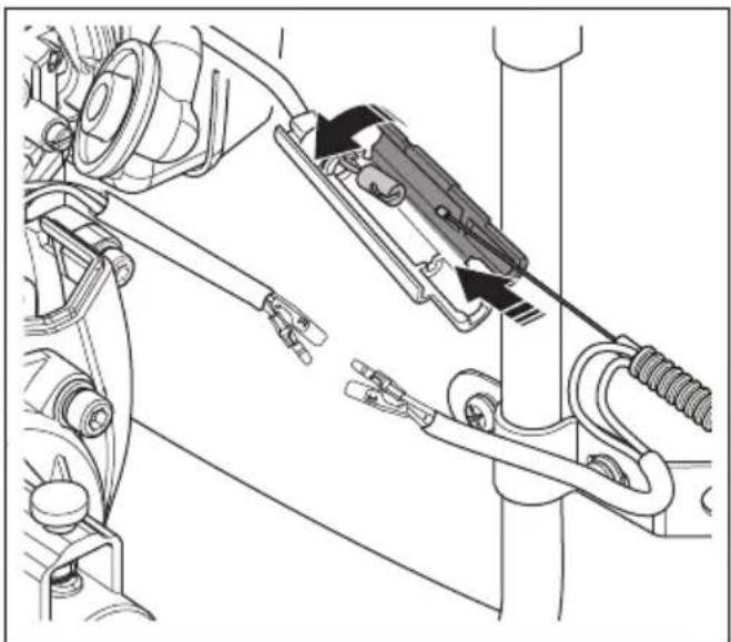
natural_image
Mechanical assembly diagram showing a mechanical component with attached parts and directional arrows indicating motion (no text or labels)- Connect the cables.
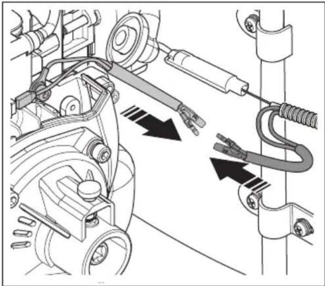
natural_image
Mechanical assembly diagram showing motor components and spring-loaded parts (no text or labels)To install a blade guard and grass blade

CAUTION: Only use the approved guard for the blades. See ACCESSORIES on page 20.
- Attach the blade guard/cutting attachment guard (A) onto the shaft and tighten with the bolt (L).
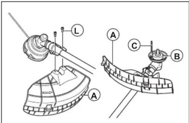
- Install the drive disc (B) on the output shaft.
- Turn the output shaft until one of the holes in the drive disc aligns with the related hole in the gear housing.
- Put the locking pin (C) in the hole to lock the shaft.
- Put the blade (D), support flange (G) and support cup (F) on the output shaft.
-
Put the support cup (F) on the output shaft with the not flat side against the blade.
-
Install the nut (E). Hold the shaft of the wrench near the blade guard as much as possible. To tighten the nut, you must turn the wrench in the opposite direction of rotation. Tighten the nut to a torque of 35-50 Nm (3.5-5 kpm).
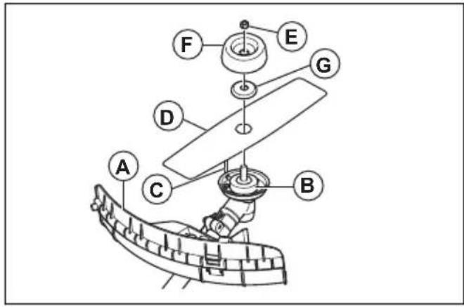
Note: Left hand thread.
To install blades and trimmer heads

WARNING: Only use the approved guard for the blades. See ACCESSORIES on page 20. A defective guard can cause injury.

WARNING: If you operate the product with a grass blade, first install the correct handlebar, blade guard and harness.

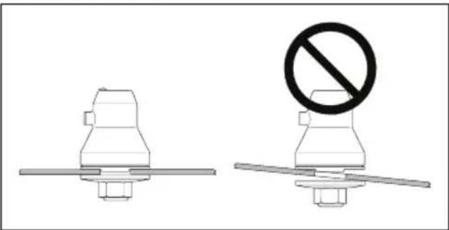
WARNING: If you do not install the the blades correctly, it can cause injury.
-
Make sure that the lifted section on the drive disc/support flange engages correctly in the center hole of the blades.
-
Install the blades.
natural_image
Two mechanical components with a no-smoking symbol, one plain and one with a circular cross (no text or labels)To attach the trimmer guard and the trimmer head
- Attach the guard (A) to the shaft with the bolts (L). Make sure to use the correct guard for the correct trimmer head.
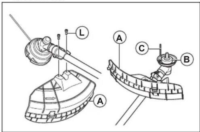
- Attach the drive disc (B) and support flange (G) to the output shaft.
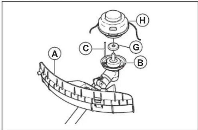
-
Turn the output shaft until the hole in the drive disc aligns with the hole in the gear housing.
-
Put the locking pin (C) in the hole to lock the shaft.
-
Turn the trimmer head (H) counterclockwise.
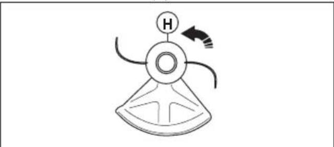
natural_image
Simple line drawing of a conical device with a labeled H and directional arrow (no text or symbols)- To disassemble, do the reverse procedure.
To install the transport guard
- Attach the transport guards on the blade.
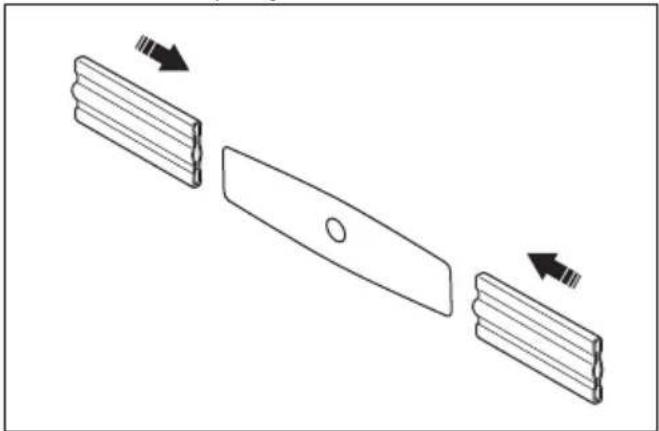
natural_image
Diagram showing three stages of a mechanical component with arrows indicating direction (no text or symbols)To adjust the harness

WARNING: The product must always be correctly attached to the harness. Do not use a defective harness.
- Put on the harness.
- Adjust the harness for the best work position.
- Adjust the side straps until the weight is the same across your shoulders.
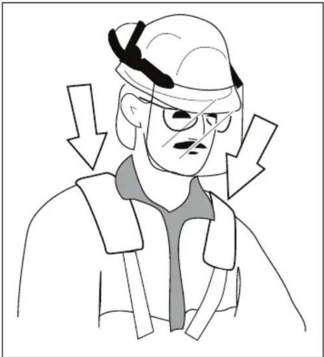
natural_image
Cartoon illustration of a character wearing a cap and glasses, with downward arrows indicating pressure or stress (no text or symbols)- Adjust the harness until the cutting attachment is parallel to the ground.
- Let the cutting attachment stay lightly on the ground. And then adjust the harness clamp to balance the product correctly.
Note: If you use a grass blade, it must balance approximately 10 cm (4 in) above the ground to keep the grass blade from hitting the ground.
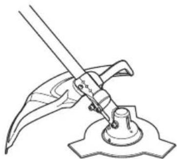
To install the liner
- Remove the bolt (A) on the joint (B) of the outer pipe.
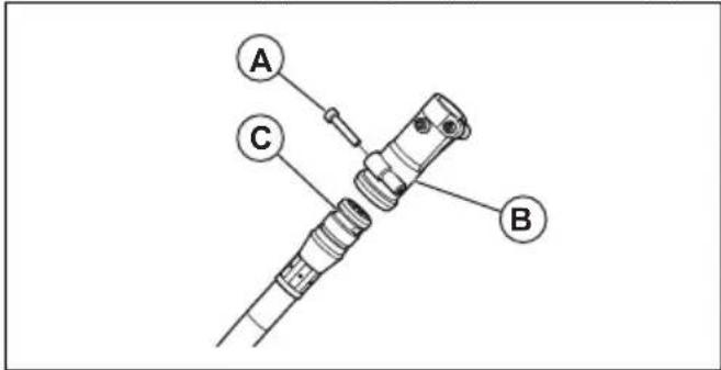
- Align the groove (C) of the liner with the thread hole and tighten the screw.
- Turn the flexible shaft (D) at the opposite end from the liner (E) to install it into the joint (B) tightly.
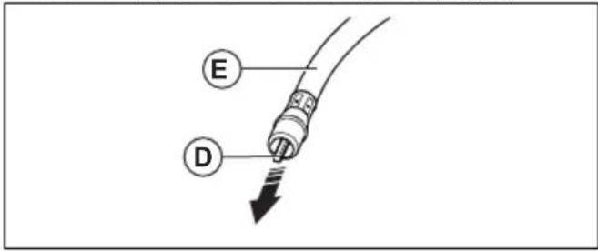
IMPORTANT: After you connect the inner shaft to the shaft of the outer pipe, pull on the flexible shaft by hand to make sure the flexible shaft does not come off.
- Put the liner (E) straight and align the flexible shaft (D) with the angular hole (G) on the side of the clutch drum.
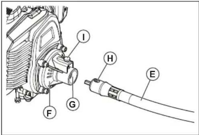
- Install the liner (E) into the clutch housing (F). Make sure that the hole on the end of the liner points directly up.
-
When the hole (H) moves directly below the stopper (I), you can hear a click which means the stopper locks the liner.
-
If you cannot lock the liner (E) into position, pull it out.
- Turn the flexible shaft a small distance and try to lock the liner (E) again.
OPERATION

WARNING: Read and understand the safety chapter before you operate the product.
Fuel
To use fuel

CAUTION: This product has a two-cycle engine. Use a mixture of gasoline and two-cycle engine oil. Make sure to use the correct quantity of oil in the mixture. Incorrect ratio of gasoline and oil can cause damage to the engine.
Gasoline

CAUTION: Do not use gasoline with an octane number less than 90 RON (87 AKI). This can cause damage to the product.

CAUTION: Do not use gasoline with more than 10% ethanol concentration (E10). This can cause damage to the product.
• Always use new unleaded gasoline with a minimum octane number of 90 RON (87 AKI) and with less than 10% ethanol concentration (E10).
- Use gasoline with a higher octane number if you frequently use the product at continuously high engine speed.
Two-cycle engine oil
- Use only the two-cycle engine oil of high quality, especially HUSQVARNA two-cycle oil. Use only the oil of an air cooled engine.
• Mixture ratio 1:40 (2.5%). - Oil of low quality and high oil/fuel ratio can decrease the lifetime of catalytic converters.
- Speak to your dealer when you select an oil.
- If Husqvarna two-stroke oil is not available, you can use another two-stroke oil of good quality that is intended for air cooled engines. Contact your dealer when you select oil.
- Do not use the two-stroke oil for water-cooled outboard engines. The two-stroke oil is sometimes referred to as outboard oil.
| Gasoline,litre | Oil,litre |
| 2.5%(1:40) | |
| 5 0,125 |
| Gasoline,litre Oil,litre | |
| 10 0,25 | |
| 15 0,375 | |
| 20 0,50 |
To make the fuel mixture
Note: Always use a clean fuel container when you mix the fuel.
Note: Do not make more than 30 days quantity of fuel mixture.
- Add half of the gasoline quantity.
- Add the full quantity of oil.
- Shake the fuel mixture to mix the contents.
- Add the remaining gasoline quantity.
- Shake the fuel mixture to mix the contents.
- Fill the fuel tank.
To add fuel
• Always use a fuel container with an antispill valve.
- If there is some fuel on the container, remove the unwanted fuel and let the container dry.
- Make sure that the area near the fuel tank cap is clean.
- Shake the fuel container before you add the fuel mixture to the fuel tank.
To start and stop
To examine before start
- Examine the product for missing, damaged, loose or worn parts.
- Examine the nuts, screws and bolts.
- Examine the blades.
- Examine the locknut. Make sure that the locknut has a minimum locking force of 1.5 Nm (1,1 ft lb). Torque the locknut to 35-50 Nm (26-36 ft lb).
- Examine the air filter.
- Examine the throttle trigger lockout and the throttle control.
- Examine the stop switch.
- Examine the product for fuel leaks.
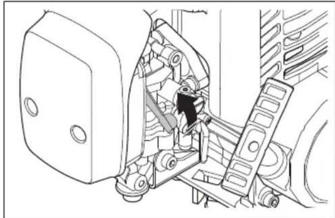
To start a cold engine
-
Set the stop switch to the start position.
-
Push the start throttle button.
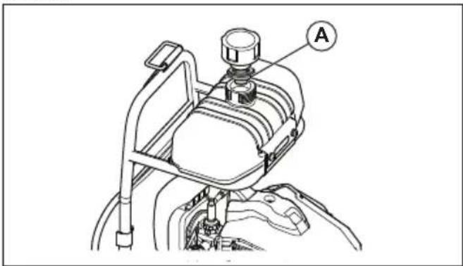
- Turn the knob counterclockwise to a vertical position to open the valve of the fuel tank.
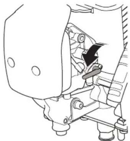
natural_image
Technical line drawing of a mechanical assembly with no visible text or symbols- Set the choke control in the choke position.
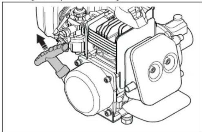
natural_image
Technical line drawing of a mechanical assembly with no visible text or symbols- Hold the product to the ground. Pull out the cord slowly with your right hand until you feel some resistance. Pull the cord quickly and with force. Keep doing it until you hear the engine start.
natural_image
Technical line drawing of a mechanical assembly with no visible text or symbols
WARNING: Use the starter rope handle. Do not twist the starter rope around your hand.

CAUTION: Do not pull all the starter rope out. Do not let go of the starter rope handle when the cord is fully extended.
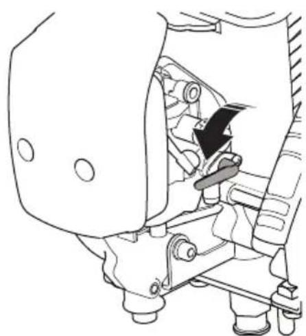
- Set the choke control to the run position, then pull the start rope until the engine starts.
- Pull the throttle trigger lightly and run at low speed for 60 seconds.
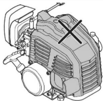
natural_image
Technical illustration of a mechanical engine assembly (no text or symbols visible)
WARNING: Do not touch the cover. The cover can burn your skin and cause electrical shock if the spark plug cap is damaged. Do not use a product with damaged spark plug cap..
To start a warm engine
- Set the stop switch to the start position.
- Turn the knob counterclockwise to a vertical position to open the valve of the fuel tank.
natural_image
Technical line drawing of a mechanical assembly with no visible text or symbols- Set the choke control to the run position.
- Pull the cord quickly with force. Keep doing it until the engine starts.
To stop
- Push the stop switch to stop the engine.
natural_image
Technical line drawing of a mechanical device with a black arrow pointing to a component (no text or symbols present)To operate the grass trimmer

CAUTION: Make sure that you slow the engine to idle speed after each operation. A long period at full throttle without a load on the engine can cause damage to the engine.
Note: Clean the cover of the trimmer head when you attach a new trimmer line to prevent vibrations. Examine other parts of the trimmer head and clean if it is necessary.
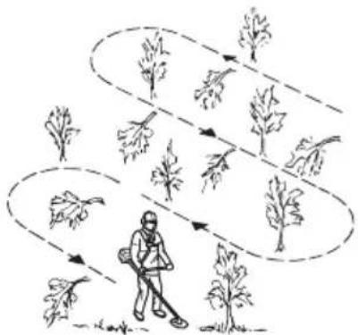
General work instructions

WARNING: Be careful when you cut a tree that is in tension. It can spring back to its normal position before or after the cut and hit you or the product, and cause injury.
- Clear an open space at one end of the work area, and start the work from there.
- Move in a regular pattern across the work area.
flowchart
graph TD
    A["Start"] --> B["Leaf Growth"]
    B --> C{Branching}
    C -->|Yes| D["Leaf Growth"]
    C -->|No| E["Stable Plant"]
    D --> F["Leaf Growth"]
    E --> G["Stable Plant"]
- Move the product fully to the left and right, to clear a width of 4–5 m (13-16 ft) on each turn.
- Clear a length of 75 m (250 ft) before you turn and go back. Move the fuel can along with you as you continue.
- Move in a direction where you do not go across ditches and obstacles more than necessary.
- Move in a direction where the wind makes the cut vegetation fall in the cleared area.

natural_image
Illustration of a person walking with a long pole, surrounded by trees and pathways (no text or symbols)- Move along slopes, not up and down.
To clear grass with a grass blade
- Grass blades and grass cutters must not be used on woody stems.
- A grass blade is used for all types of tall or coarse grass.
- The grass is cut down with a sideways, swinging movement, where the movement from right-to-left is the clearing stoke and the movement from left-to-right is the return stoke. Let the left-hand side of the blade (between 8 and 12 o'clock) do the cutting.
- if the blade is angled to the left when clearing grass, the grass will collect in a line, which makes it easier to collect, e.g. by raking.
- Try to work rhythmically. Stand firmly with your feet apart. Move forward after the return stoke and stand firmly again.
- Let the support cup rest lightly against the ground. It is used to protect the blade from hitting the ground.
- Reduce the risk of material wrapping around the blade by always work at full throttle and avoid the previously cut material during the return stoke.
- Stop the engine, unclip the harness and place the machine on the ground before you start to collect the cut material.
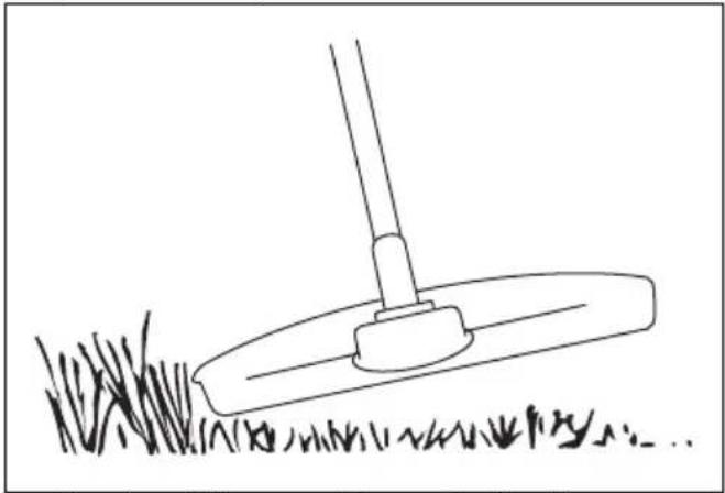
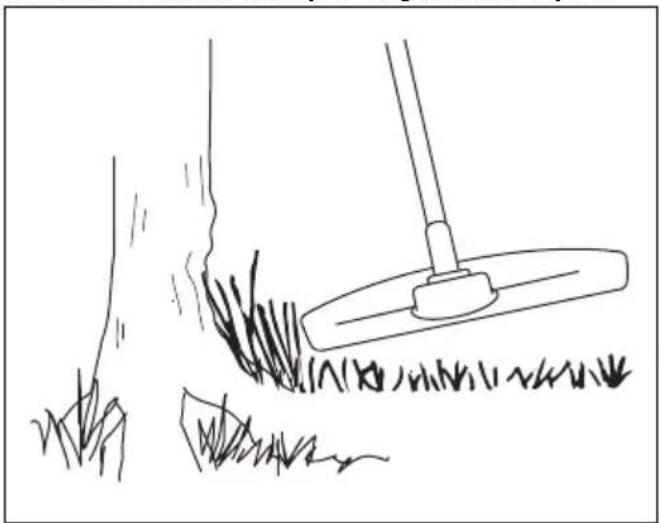
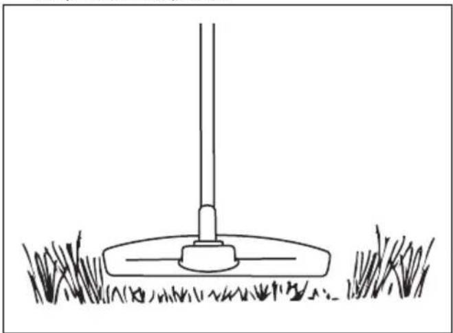
To trim the grass
- Hold the trimmer head immediately above the ground at an angle.
natural_image
Line drawing of a grassy field with a flatbed tool, no text or symbols presentDo not push the grass trimmer line into the grass.
- Decrease the length of the grass trimmer line by 10-12 cm (4-4.75 in) and decrease engine speed to decrease the risk of damage to plants.
- Use 80 % throttle when you cut grass near objects.
natural_image
Line drawing of a grassy field with a tool and a small object, no text or symbols presentTo cut the grass
- Make sure that the grass trimmer line is parallel to the ground when you cut.
natural_image
Simple line drawing of a grassy field with a vertical pole and base, no text or symbols present.- Do not push the trimmer head to the ground. The ground and the product can be damaged.
- Do not let the trimmer head touch the ground continuously, it can cause damage to the trimmer head.
- Use full throttle when you move the product from side to side to cut grass. Make sure that the grass trimmer line is parallel to the ground.
natural_image
Diagram of a hand holding a tool with a dashed arrow indicating direction (no text or symbols)To sweep the grass
The airflow from the rotating trimmer line can be used to remove cut grass from an area.
- Hold the trimmer head and its trimmer line parallel to the ground and above the ground.
- Apply full throttle.
- Move the trimmer head from side to side and sweep the grass.

WARNING: Clean the trimmer head cover each time you assemble new trimmer line to prevent unbalance and vibrations in the handles. Also do a check of the other parts of the trimmer head and clean it if necessary.
To replace trimmer line
Refer to 593707601 on page 21
MAINTENANCE

WARNING: Read and understand the safety chapter before you clean, repair or do maintenance on the product.
product. The intervals are different if you do not use the product each day. Only do the maintenance work that is found in this manual. Speak to an approved service center about other maintenance work not found in this manual.
Maintenance schedule
Make sure that you obey the maintenance schedule.
The intervals are calculated from daily use of the
| Maintenance schedule Daily Weekly Monthly | |||
| Clean the external surfaces. √ | |||
| Clean the air filter. Replace if necessary. √ | |||
| Do a check of the harness. √ | |||
| Do a check of the throttle trigger lock and the throttle function. √ | |||
| Do a check of the handle and the handlebar. √ | |||
| Do a check of the stop switch. √ | |||
| Do a check of the guards. √ | |||
| Do a check of the blade that it is sharp and not damaged. Install the blade to the center position correctly. | √ | ||
| Do a check of the trimmer head. √ | |||
| Do a check of the idle speed. √ | |||
| Do a check of the locknut. √ | |||
| Do a check of fuel leaks. √ | |||
| Do a check of the transport guard. √ | |||
| Do a check of the starter rope handle and the starter rope. √ | |||
| Do a check of the bevel gear grease. √ | |||
| Clean the external part and the adjacent areas of the carburettor. | √ | ||
| Clean the external part of the spark plug. Remove it and check the electrode gap. Adjust the distance or replace the spark plug. Install a correct spark plug to the suppressor. | √ | ||
| Clean the cooling system. | √ | ||
| Do a check of the fuel filter. | √ | ||
| Do a check of the fuel hose. | √ | ||
| Do a check of all cables and connections. | √ |
To adjust the carburetor
The basic carburetor settings are adjusted during testing at the factory. Adjustment must be carried out by a trained technician.
To do a check of the muffler

WARNING: Do not use a product that has a defective muffler. Always replace a defective muffler.

WARNING: Risk of burn or fire. Mufflers with catalytic converters get very hot during operation.

WARNING: Risk of fire. The muffler decreases the noise level and identifies the exhaust gases from the operator. The exhaust gases are hot and can contain sparks.

CAUTION: The spark arrester screen must be replaced if it is damaged. Do not use a product if the spark arrester screen on the muffler is missing or defective.

CAUTION: If the spark arrester screen is blocked, the product will be too hot. This will cause damage to the cylinder and piston.
- Make sure that the muffler is not damaged.
- Make sure that the muffler is correctly attached to the product.
- Some mufflers have a special spark arrester screen. Clean the spark arrester screen at a minimum of one time a week if your product has this type of muffler. Use a wire brush.
natural_image
Line drawing of a rectangular electronic device with three circular cutouts and a cylindrical port (no text or symbols)Cooling system
The product has a cooling system to keep the work temperature low.
The cooling system has:
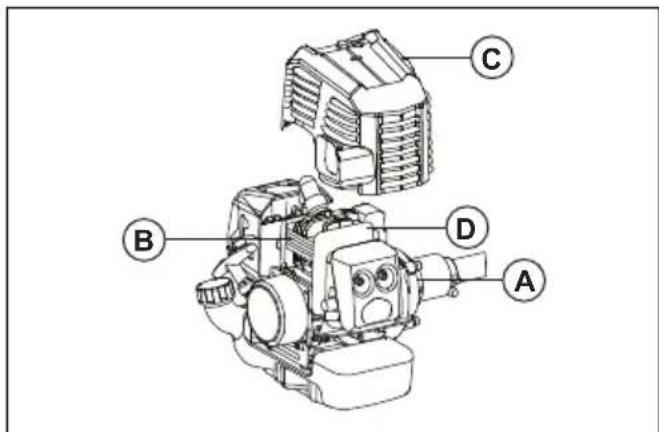
- Fins on the flywheel (A)
• Cooling fins on the cylinder (B)
• Cylinder cover (C) (directs cold air over the cylinder) - Muffler plate (D)
To clean the cooling system

WARNING: A dirty or blocked cooling system causes overheating. It causes damage to the piston and cylinder.
- Clean the parts of the cooling system with a brush a minimum of one time a week.
To clean the air filter
- Remove the air filter cover and remove the air filter.
natural_image
Mechanical assembly diagram showing a motor, gear shift, and housing components (no text or labels)- Clean the air filter with warm soap water. Make sure that the air filter is dry before you install it.
- Replace the air filter if it is too dirty to fully clean it. Always replace a damaged air filter.
- If your product has a foam air filter, apply air filter oil. Only apply air filter oil to a foam filter. Do not apply oil to a felt filter.
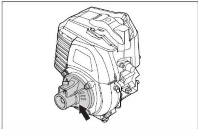
Fuel filter
When the engine runs short of fuel supply, make sure that the fuel tank cap and the fuel filter (A) is not blocked.
To add grease to the bevel gear
Make sure that the bevel gear is filled 3/4 full with bevel gear grease.
natural_image
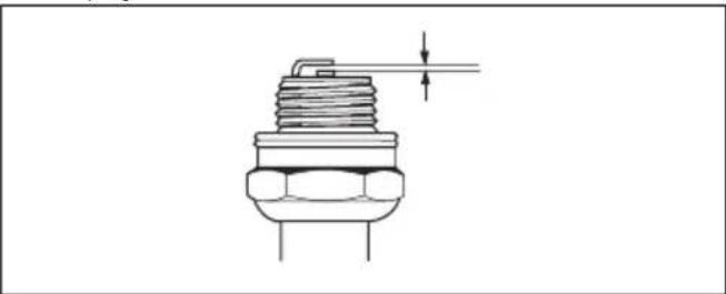
Technical line drawing of a mechanical assembly with a lever and base mount (no text or symbols)To examine the spark plug

CAUTION: Always use the recommended spark plug type. Incorrect spark plug type can cause damage to the product.
- Examine the spark plug if the engine is low on power, is not easy to start or does not operate correctly at idle speed.
• To decrease the risk of unwanted material on the spark plug electrodes, obey these instructions:
a) Make sure that the idle speed is correctly adjusted.
b) Make sure that the fuel mixture is correct.
c) Make sure that the air filter is clean.
- If the spark plug is dirty, clean it and make sure that the electrode gap is correct, see TECHNICAL DATA on page 19.
natural_image
Technical line drawing of a mechanical component with threaded base and shaft (no text or symbols)- Replace the spark plug if it is necessary.
To sharpen grass cutters and grass blades
-
Sharpen grass cutters and grass blades with a single-cut flat file.
-
Sharpen all edges of the grass cutters and blades equally to keep the balance.
natural_image
Technical line drawing of a tool and blade assembly (no text or symbols)TROUBLESHOOTING
Starting failure
| Starting failure | ||
| Check Possible cause Solution | ||
| Stop button Stop position Set the stop switch to the start position. | ||
| Starter pawls Binding pawls Adjust or replace the pawls. | ||
| Fuel tank Incorrect fuel type. | Drain it and use correct fuel. | |
| Carburettor Adjustment of the idle speed. | Adjust the idle speed with the T-screw. | |
| Spark (no spark) | Spark plug dirty or wet. | Make sure that the spark plug is dry and clean. |
| Spark plug clearance incorrect. | Clean the spark plug. Check that the electrode gap is correct. Make sure that the spark plug is installed with a suppressor. | |
| Refer to technical data for correct electrode gap. | ||
| Spark plug Spark plug loose. | Tighten the spark plug. | |
| Engine starts but does not stay running | ||
| Check Possible cause Solution | ||
| Fuel tank Incorrect fuel type. | Drain it and use correct fuel. | |
| Carburettor Engine will not idle correctly. | Speak to your servicing dealer. | |
| Air filter Clogged air filter. | Clean the air filter. | |
TRANSPORTATION AND STORAGE
- Keep equipment safe during transportation to prevent damage and accidents.
- Keep the product and equipment in a dry and frost-proof area.
-
Clean the product.
-
Replace or repair damaged components.
- Use the correct protective cover on the product that does not keep moisture.
- Keep the product tightly attached during transport.
TECHNICAL DATA
| unit 131RB | ||
| Engine specifications | ||
| Cylinder displacement cm | ^3 | 32,6 |
| Cylinder bore mm 36,0 | ||
| Stroke mm 32,0 | ||
| Idling speed rpm 3500±300 | ||
| Maximum speed rpm 9600 | ||
| Speed of output shaft rpm 7100 | ||
| Maximum engine output kW/rpm 0,9/7000 | ||
| Spark plug NGK BPMR7A | ||
| Electrode gap mm 0,6-0,7 | ||
| Fuel tank capacity cm | 3 | 1150 |
| Noise and vibration data | ||
| Equivalent vibration level (ahv, eq), equipped with grass blade, front/back handle - see note 1 | m/s2 | 4.58/2.58 |
| Equivalent vibration level (ahv, eq) equipped with trimmer head, front/back handle - see note 1 | m/s2 | 6.58/6.86 |
| Sound power level, guaranteed (LWA) - see note 2 dB(A) 115 | ||
| Sound power level, measured - see note 2 dB(A) 111,9 | ||
| Sound pressure level at operator's ear, equipped with grass blade - see note 3 | dB(A) 92,4 | |
| Sound pressure level at operator's ear, equipped with trimmer head - see note 3 | dB(A) 93,6 | |
| Product dimensions | ||
| Weight (excluding cutting equipment) kg 10,2 | ||
| Note 1: Reported data for equivalent vibration level has a typical statistical dispersion (standard deviation) of 1.5 m/s2. Note 2: Noise emissions in the environment measured as sound power (LWA) in conformity with EC directive 2000/14/ EC. Reported sound power level for the machine has been measured with the original cutting attachment that gives the highest level. The difference between guaranteed and measured sound power is that the guaranteed sound power also includes dispersion in the measurement result and the variations between different machines of the same model according to Directive 2000/14/EC. Note 3: Reported data for equivalent sound pressure level for the machine has a typical statistical dispersion (standard deviation) of 2.5 dB (A). | ||
ACCESSORIES
| 131RB | ||
| Approved accessories | Type Cutting attach- | ment guard |
| Grass blade/grass cutter | Multi 255-3 (∅ 255 3 teeth) 593 70 66-01 | |
| Grass 275-4 (∅ 275 4 teeth) 593 70 66-01 | ||
| Grass 255-4 1" (∅ 255 4 teeth) 593 70 66-01 | ||
| Trimmer head 593707601 | 593 70 66-01 | |
| Support cup | Fixed | - |
1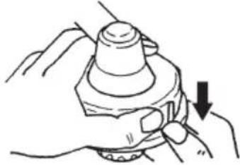 | 2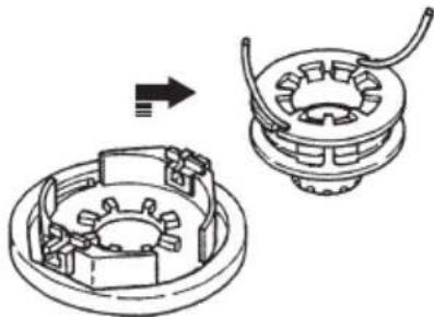 |
3 4.7 in.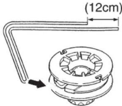 | 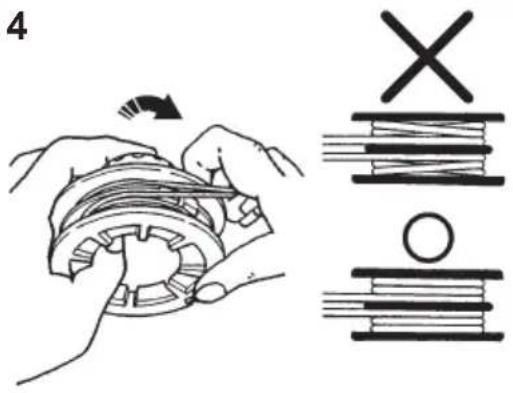 |
5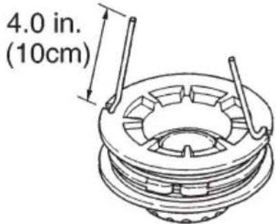 | 6 |
7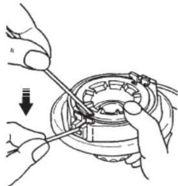 | 8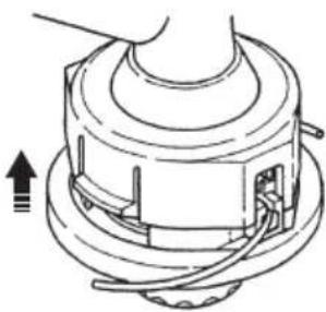 |
Husqvarna®
www.husqvarna.com
Original instructions
1159702-26

2018-05-25