CM 51 - Multimeter BENNING - Free user manual and instructions
Find the device manual for free CM 51 BENNING in PDF.

User questions about CM 51 BENNING
0 question about this device. Answer the ones you know or ask your own.
Ask a new question about this device
Download the instructions for your Multimeter in PDF format for free! Find your manual CM 51 - BENNING and take your electronic device back in hand. On this page are published all the documents necessary for the use of your device. CM 51 by BENNING.
USER MANUAL CM 51 BENNING
Multilingual manuals on included CD and at
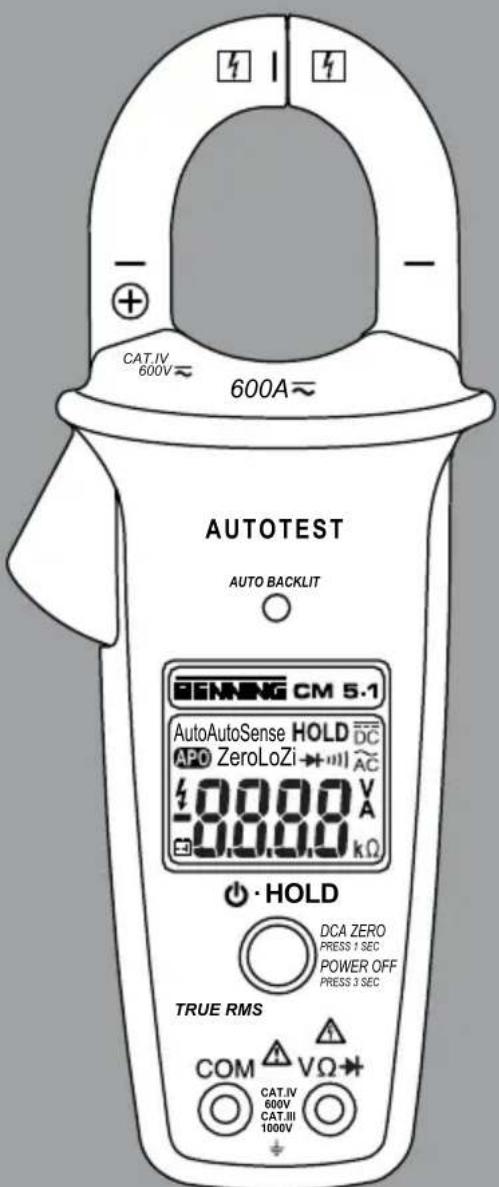
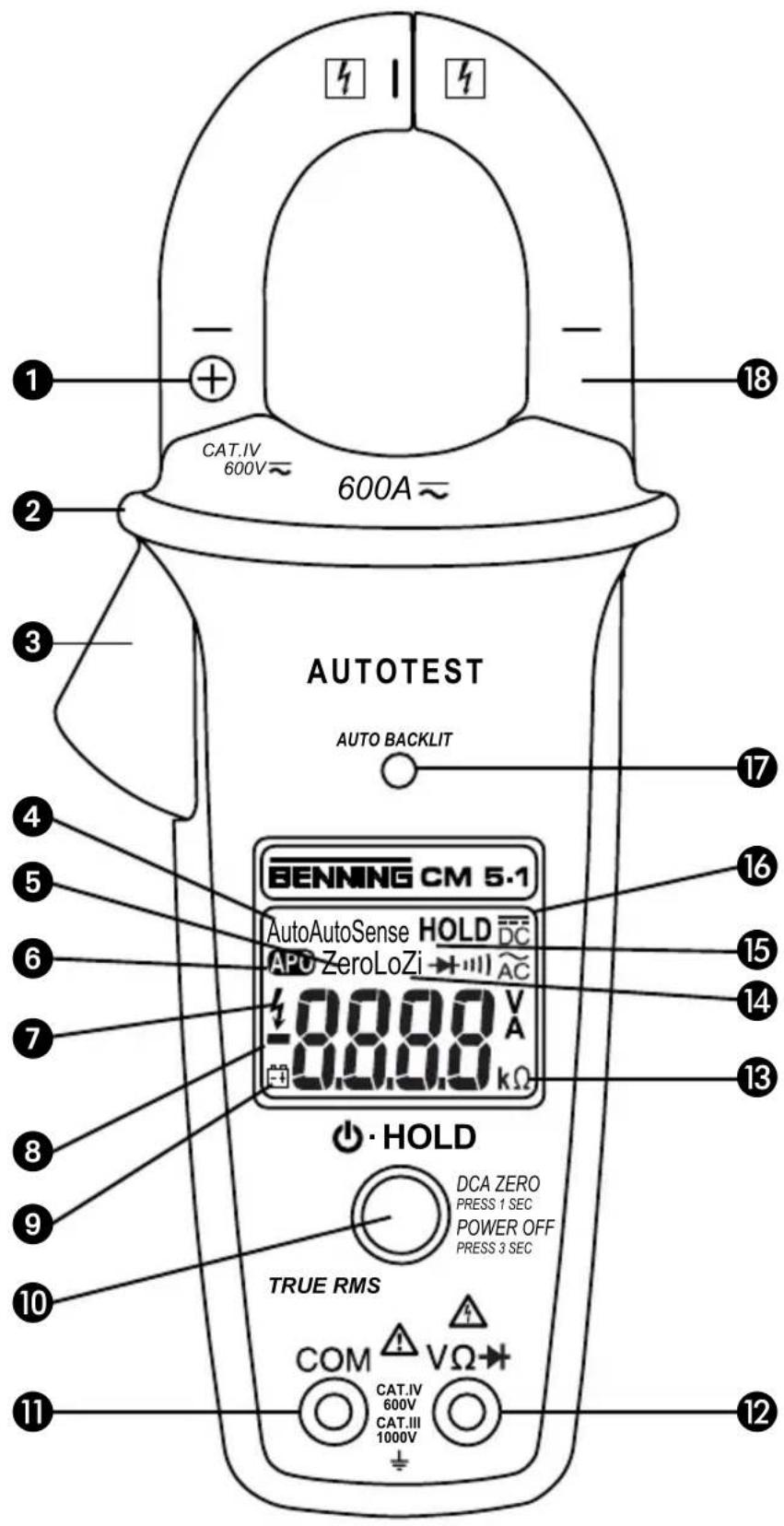
Bild 1: Gerätefrontseite
Fig.1: Front tester panel
Fig.1: Panneau avant de I'appareil
Fig.1: Parte frontal del equipo
Obr.1: Predni strana pristroje
ΣIKAva 1: Mtnpoovn oyn
1. ábra: A merokszülék elönlēzete
III.1: Lato anterioe apparecchio
Fig.1: Voorzijde van het apparatusat
Rys.1: Panel przyrdz
Imaginea 1: Partea frontala a aparutuli
Pnc.1: Buid cnepein
Fig.1: Framsida
Resim 1: Cihaz onyuzu
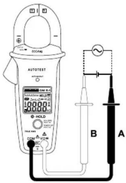
Fig.2:Direct/alternating voltage measurement with AUTOTEST function
Fig. 3: Direct/ alternating current measurement with AUTOTEST function
Fig. 4: Resistance measurement
Fig. 5: Continuity testing with buzzer
Fig. 7: Battery replacement
Fig. 7: Remplacement de la pile
Fig. 7: Cambio de pila
Operating instructions BENNING CM 5-1
Digital current clamp multimeter with AUTOTEST function for
- Direct voltage measurements
- Alternating voltage measurements
- Direct current measurements
- Alternating current measurements
- Resistance measurements
- Continuity testing
- Diode testing
Table of contents
- User notes
- Safety note
- Scope of delivery
- Unit description
- General information
- Ambient conditions
- Electrical specifications
- Measuring with the BENNING CM 5-1
- Maintenance
- Technical data of the measuring accessories
- Environmental note
1. User notes
These operating instructions are intended for
- qualified electricians and
- electrotechnically trained persons.
The BENNING CM 5-1 is intended for making measurements in dry environment. It must not be used in power circuits with a nominal voltage higher than 1000V DC and 750V AC (More details in Section 6. "Ambient conditions").
The following symbols are used in these operating instructions and on the BENNING CM 5-1:

Application around and removal from HAZARDOUS LIVE conductors is permitted.

Warning of electrical danger!
Indicates instructions which must be followed to avoid danger to persons.

Important, comply with the documentation!
The symbol indicates that the information provided in the operating instructions must be followed with in order to avoid risks.

This symbol on the BENNING CM 5-1 means that the BENNING CM 5-1 is totally insulated (protection class II).

This symbol on the BENNING CM 5-1 means that the BENNING CM 5-1 complies with the EU directives.

This symbol appears on the display to indicate a discharged battery.

This symbol designates the "continuity test" range. The buzzer is used for the acoustic result output.

(DC) Direct voltage or current.

(AC) Alternating voltage or current.

Ground (Voltage against ground).
Note
After unmark the adhesive label „Warning...“ (on battery compartment lid) the English text appears.
2. Safety note
The instrument is built and tested in accordance with
DIN VDE 0411 part 1/EN 61010-1
DIN VDE 0411 part 2-032/EN 61010-2-032
DIN VDE 0411 part 2-033/EN 61010-2-033
DIN VDE 0411 part 031/EN 61010-031
and has left the factory in perfectly safe technical condition.
To maintain this condition and to ensure safe operation of the multimeter, the user must observe the notes and warnings given in these instructions at all times. Improper handling and non-observance of the warnings might involve severe injuries or danger to life.

WARNING! Be extremely careful when working with bare conductors or main line carrier! Contact with live conductors will cause an electric shock!

The BENNING CM 5-1 may be used only in electrical circuits of over voltage category III with a maximum voltage of 1000V or of over voltage category IV with a maximum voltage of 600V between the conductor and ground.
Only use suitable measuring leads for this. With measurements within measurement category III or measurement category IV, the projecting conductive part of a contact tip of the measuring leads must not be longer than 4mm
Prior to carrying out measurements within measurement category III and measurement category IV, the push-on caps provided with the set and marked with CAT III and CAT IV must be pushed onto the contact tips. The purpose of this measure is user protection.
Remember that work on electrical components of all kinds is dangerous. Even low-voltages of 30V AC and 60V DC may be dangerous to human life.

Before starting the multimeter, always check it as well as all measuring leads and wires for signs of damage.
Should it appear that safe operation of the multimeter is no longer possible, it should be shut down immediately and secured to prevent that it is switched on accidentally.
It may be assumed that safe operation is no longer possible:
- if the instrument or the measuring leads show visible signs of damage, or
- if the multimeter no longer works, or
- after long periods of storage under unfavourable conditions, or
- after being subject to rough transportation, or
- if the device or the measuring leads are exposed to moisture, or
- if the self-test fails and „FAIL“ is shown on the display.

In order to avoid danger,
- do not touch the bare probe tips of the measuring leads,
- insert the measurement leads in the appropriately designated measuring sockets on the multimeter

Maintenance:
Do not open the multimeter, because it contains no components which can be repaired by the user. Repair and service must be carried out by qualified personnel only!

Cleaning:
Regularly wipe the housing by means of a dry cloth and cleaning agent. Do not use any polishing agents or solvents!
3. Scope of delivery
The scope of delivery for the BENNING CM 5-1 comprises:
3.1 one BENNING CM 5-1,
3.2 one safety measuring leads, red (L = 1.4m)
3.3 one safety measuring leads, black (L = 1.4m)
3.4 one compact protective pouch,
3.5 a 9 V block battery
3.6 one operating manual
Parts subject to wear:
- The BENNING CM 5-1 is fed by a 9V block battery (IEC 6 LR 61)
- The above-mentioned safety measuring leads (tested accessories, 044145) correspond to CAT III 1000 V/ CAT IV 600 V and are approved for a current of 10 A.
4. Description of current clamp multimeter
See figure 1: Appliance front face
The display and operator control elements specified in Fig. 1 are designated as follows:
Polarity marking, for assigning the DC current direction by means of the polarity indication,
Bulge of current clamp, protects against contact with conductor,
3 Opening lever, for opening and closing the current clamp,
4 AutoSense, symbolizes the AUTOTEST function,
Zero, null-balance indication for direct current (DC) measurements,
APO, Auto Power Off is activated (device will switch off after 20 minutes),
7, is indicated if a dangerous voltage is applied >30V
Polarity indication, any polarity opposed to the polarity markings shall be designated with - ,
9 Battery status indication, appears when the battery is discharged,
10 key (grey), with the following functions:
- POWER, for switching the BENNING CM 5-1 on/ off
(AUTO) POWER OFF, for activating/ deactivating the automatic switchoff.
ZERO balance, null balance for direct current (DC) measurements,
(AUTO) HOLD, automatic storage of the measured value,
HOLD, storage of the measured value,
COM jack, common socket for voltage, resistance measurement and continuity testing,
12 Jack (positive 1), for V, and
18 Range indication,
14 LoZi, symbolizes a low input resistance for voltage measurements (4 kΩ ... 375 kΩ),
15 Auto, HOLD and AutoHOLD, is displayed if the corresponding storage of measured values is activated,
Digital display, for displaying the measured value and range exceedance,
17 AUTO BACKLIT, sensor of the automatic background lighting,
18 Measuring pliers, for clamping on the single wire current-carrying conductor,
This is what the automatic polarity indication for DC voltage refers to,
5. General information
5.1 General details on the current clamp multimeter
5.1.1 The digital display is a 4-digit liquid crystal display with 14mm high numerals, complete with decimal point. The largest numerical value which can be displayed is 9999.
5.1.2 The polarity indication is automatic. Only one polarity with respect to the socket/ polarity marking marked “-” is indicated.
5.1.3 The BENNING CM 5-1 can be switched on/ off by means of the key (grey) 10. For switching it off, press and hold the key for approx. 3 seconds.
5.1.4 The overranging is indicated by "0L" or "- 0L" and, in part, an acoustic warning.
Warning, no indication and prior warning in the event of an overload condition!
5.1.5 Null balance (ZERO)
Press the key (grey) 10 for approx. 1 second to carry out a null balance for direct current (DC) measurements. The null balance is indicated by a flashing _ZERO" symbol 5 on the digital display.
5.1.6 Storage of measured values "HOLD": The measuring result can be stored by actuating the key (grey) 10. The "HOLD" symbol 15 simultaneously appears on the display. By pressing the key 10 again, the device is switched back to the measuring mode.
With the storage of measured values "HOLD" being activated, the multimeter recognizes a measuring signal deviating from the displayed value, if the measuring signal of the same unit has increased by 50 digits or if a measuring signal of another measuring function is detected. The change of measuring signal is indicated by a flashing display or by a continuous acoustic signal.
5.1.7 Automatic storage of measured values „AutoHOLD" (only for AC/ DC measurements higher than 3 A): If during switch-on the key (grey) is
pressed for more than 5 seconds, the "AutoHOLD" symbol ⑤ flashes on the display and "AutoHOLD" is activated. If the multimeter detects a constant measured value, the buzzer can be heard three times and the measured value will be shown on the display together with the "AutoHOLD" symbol for approx. 5 seconds. The measured value can be stored by actuating the key (grey) ⑩. With the "AutoHOLD" function being activated, the APO function is deactivated.
5.1.8 The measuring rate of the BENNING CM 5-1 amounts nominally to 5 measurements per second for the digital display.
5.1.9 The BENNING CM 5-1 is provided with a self-test function. Do not use the BENNING CM 5-1, if "FAIL" is shown on the display. In case of an error, switch the device off an on again. If the error persists, send the BENNING CM 5-1 to our service address (see section 9.4 "Calibration").
5.1.10 The BENNING CM 5-1 is switched off automatically after approx. 20 minutes (APO, Auto-Power-Off). It switches on again when the key (grey) 10 is actuated. A buzzer sound indicates the automatic switch-off of the device. The automatic switch-off can be deactivated by pressing the key 10 for approx. 3 seconds during switch-on. The automatic switch-off is indicated by a flashing "APO" symbol 6 on the digital display. When switching the device on again, briefly press the key 10 to reactivate the automatic switch-off.
5.1.11 Temperature coefficient of the measured value: 0.2 × (stated measuring precision) ^ C < 18^ C or >28^ , related to the value for the reference temperature of 23^ .
5.1.12 The BENNING CM 5-1 is supplied by a fitted 9V block battery (IEC 6 LR 61).
5.1.13 If the battery voltage drops below the specified operating voltage of the BENNING CM 5-1, then a battery symbol appears on the display.
5.1.14 The life span of a battery amounts to approx. 125 hours (alkali battery).
5.1.15 Appliance dimensions:
(L × W × H) = 215 × 85 × 51 ~mm
Appliance weight: 360 g
5.1.16 The safety measuring leads supplied are expressly suited for the rated voltage and the rated current of the BENNING CM 5-1.
5.1.17 Largest opening of pliers: 35mm
5.1.18 Largest cable diameter: 30mm
6. Ambient conditions:
- The BENNING CM 5-1 is intended for making measurements in dry environment.
- Maximum barometric elevation for making measurements: 2000 m ,
- Overvoltage category/ setting category: IEC 60664-1/ IEC 61010-1 600V category IV, 1000V category III
- Contamination class: 2,
- Protection class: IP 30 (DIN VDE 0470-1 IEC/ EN 60529)
IP 30 means: Protection against access to dangerous parts and protection against solid impurities of a diameter >2.5mm , (3 - first index). No protection against water, (0 - second index).
- Operating temperature and relative humidity:
For operating temperatures from 0^ to 30^ : relative humidity less than 80%
For operating temperatures from 31^ to 40^ : relative humidity less than 75%
For operating temperatures from 41^ to 50^ : relative humidity less than 45%
- Storage temperature: The BENNING CM 5-1 can be stored at any temperature within the range of -20^ to +60^ (relative humidity from 0 to 80% ). The battery should be removed from the instrument for storage.
7. Electrical specifications
Note: The measuring precision is specified as the sum of
- a relative fraction of the measured value and
- a number of digits (counting steps of the least significant digit).
This specified measuring precision is valid for temperatures within the range of 18^ to 28^ and for a relative humidity lower than 80% .
7.1 Priority of the AUTOTEST function
The AUTOTEST function automatically switches to the correct measuring function and automatically selects the ideal measuring range: For this, the BENNING CM 5-1 works according to the following order:
| The following criteria must be met: | |
| VAC, VDC whichever is greater | Voltage measurement active, if: 1.3 VAC ... 750.0 VAC 2.1 VDC ... 999.9 VDC - 0.7 VDC ... - 999.9 VDC |
| Ω / Diode | Resistance measurement active, if 0 Ω ... ∞ Ω 0.0 VAC ... 0.9 VAC - 0.4 VDC ... - 0.2 VDC 1.0 VDC ... 2.0 VDC |
| Diode test active, if: 0.4 VDC ... 0.8 VDC (forward voltage) | |
| AC, ADC whichever is greater | Current measurement active, if: 0.9 AC ... 600.0 AC 0.9 ADC ... 600.0 ADC |
7.2 Direct voltage ranges
The input resistance for voltages of up to 30V is at least 4k . The input resistance increases to 375k for 750V with the input voltage increasing as well.
| Measuring range Resolution Meas. precision | Overload protection*1 | ||
| 2.1 V ... 1000 V | 0.1 V ± (0.3 % of the measuring value + 2 digits) | 750 V | eff |
| -0.7 V ... - 1000 V | 0.1 V ± (0.3 % of the measuring value + 2 digits) | 750 V eff | |
Maximum measuring time = 30 seconds for voltages higher than 30 V
7.3 Alternating voltage ranges
The input resistance for voltages of up to 30V is at least 4k . The input resistance increases to 375k for 750V with the input voltage increasing as well.
| Measuring range Resolution | Meas. precision*2 within the frequency range 50 Hz - 60 Hz | Overload protection*1 |
| 1.3 ... 750 V 0.1 V ± (0.9 % of the measuring value + 3 digits) 750 V | eff | |
| within the frequency range 61 Hz - 500 Hz | ||
| 1.3 ... 750 V | 0.1 V ± (1.5 % of the measuring value + 3 digits) | 750 Veff |
Maximum measuring time = 30 seconds for voltages higher than 30 ~V
2 The measuring value is gained and indicated as effective value (True RMS, AC coupling). The measuring accuracy is specified for sinusoidal curves and applies to the final value of the measuring range as well as for non-sinusoidal curves up to 50% of the final value of the measuring range. In case of non-sinusoidal curves, the indicating value becomes inaccurate.
Thus, an additional error occurs for the following crest factors:
- crest factor from 1.4 to 2.0 additional error + 1 %
- crest factor from 2.0 to 2.5 additional error + 2.5 %
- crest factor from 2.5 to 3.0 additional error + 4 %
7.4 Direct current ranges
| Measuring range Resolution Meas. precision | Overload protection | ||
| 0.9 A ...600.0 A | 0.1 A | ± (2.0 % of the measuring value + 5 digit) | 600 Aeff |
The indicated accuracy is specified for conductors which are gripped by means of the measuring clamp 18 in the middle (see figure 3 direct/ alternating current measurement). For conductors which are not gripped in the middle, an additional error of 1% of the indicating value has to be considered.
Maximum remanence error: 1% (during repeating measurement)
7.5 Alternating current ranges
| Measuring range | Resolution | Meas. precision *2 within the frequency range 50 Hz - 60 Hz | Overload protection |
| 0.9 A ...600.0 A | 0.1 A | ± (2.0 % of the measuring value + 5 digit) | 600 Aeff |
| within the frequency range 61 Hz - 400 Hz | |||
| 0.9 A ...600.0 A | 0.1 A | ± (2.5 % of the measuring value + 5 digit) | 600 Aeff |
2 The measuring value is gained and indicated as effective value (true RMS, AC coupling). The measuring accuracy is specified for sinusoidal curves
and applies to the final value of the measuring range as well as for nonsinusoidal curves up to 50% of the final value of the measuring range.
In case of non-sinusoidal curves, the indicating value becomes inaccurate.
Thus, an additional error occurs for the following crest factors:
crest factor from 1.4 to 2.0 additional error +1%
crest factor from 2.0 to 2.5 additional error +2.5%
crest factor from 2.5 to 3.0 additional error +4%
The stated precision is specified for conductors that are centrally clamped by the current clamp (see fig. 3 direct/ alternating current measurement). For conductors that are not centrally clamped, an additional error of 1% of the display value needs to be taken into account.
7.6 Resistance measuring range and acoustic continuity testing
Overload protection: AC 750 Veff/ DC 1000 V
Measuring range Resolution Meas. accuracy Max. idling voltage
0Ω...999Ω 1Ω±(0.9% of the measuring value + 2 digits) 1.8 V
The built-in buzzer sounds in the case of a resistance R less than 25 up to 400 . For a resistance R higher than 400 (specified for temperatures of 0^ up to 40^ ), the buzzer does not emit an acoustic signal.
7.7 Diode testing
Overload protection: AC 750 Veff / DC 1000 V
Measuring range Resolution Meas. accuracy Max. idling voltage
0.4 V ... 0.8 V 0.1 V ± (0.9 % of the measuring value + 2 digits) 1.8 V
8. Measuring with the BENNING CM 5-1
8.1 Preparations for measuring
Operate and store the BENNING CM 5-1 only at the specified storage and operating temperatures conditions. Avoid continuous insulation.
- Check rated voltage and rated current details specified on the safety measuring leads. The nominal voltage and current ratings of the safety measuring leads included in the scope of delivery correspond to the ratings of the BENNING CM 5-1.
- Check the insulation of the safety measuring leads. Discard the safety measuring leads immediately if the insulation is damaged.
- Check safety measuring leads for continuity. If the conductor in the safety measuring lead is interrupted, the safety measuring lead must be dispose of immediately.
- Strong sources of interference in the vicinity of the BENNING CM 5-1 can lead to unstable readings and measuring errors.
- It is only possible to make measurements, if the conditions of the AUTOTEST function are met (see section 7.1 „Priority of the AUTOTEST function").
Note:
Clocked signals, e.g. currents generated by chargers, might result in an incorrect AC/ DC indication.
8.2 Voltage measuring

Do not exceed the maximum permitted voltage with respect to earth potential! Electrical danger!
The highest voltage which may be applied to the jacks,
- COM socket 1
- jack for V, and
of the BENNING CM 5-1 against ground, amounts to 600V CAT IV/ 1000 V CAT III.
- Switch the BENNING CM 5-1 on by means of the key (grey) 10.
- The black safety measuring lead has to be contacted with the COM jack 11 on the BENNING CM 5-1.
- The red safety measuring lead has to be connected to the jack for V, and 12 on the BENNING CM 5-1.
- Bring the safety measuring leads into contact with the measuring points.
- On the digital display 16, the AUTOTEST function is shown by the "AutoSense" symbol 4. It automatically determines the required measuring function (voltage) and the ideal measuring range.
- Read the measured value on the digital display 16 on the BENNING CM 5-1.

Please observe the restrictions in the lower measuring range! DC voltage measurements are not possible within the range of -0.7VDC 2.1VDC AC voltage measurements are only possible starting from voltages of >1.3V_AC
See figure 2: Direct/ alternating voltage measurement with AUTOTEST function
8.3 Current measurement

Do not apply any voltage to the contacts of the BENNING CM 5-1! Any possibly connected safety measuring leads have to be removed.
- Switch the BENNING CM 5-1 on by means of the key (grey) 10.
- Operate opening lever ③, clamp single wire live conductor centrally by means of the BENNING CM 5-1 current clamp.
- On the digital display 16, the AUTOTEST function is shown by the "AutoSense" symbol 4. It automatically determines the required measuring function (current) and the ideal measuring range.
- Read the measured value on the digital display 16 on the BENNING CM 5-1.
See figure 3: Direct/ alternating current measurement with AUTOTEST function
8.4 Resistance measuring and acoustic continuity testing
- Switch the BENNING CM 5-1 on by means of the key (grey) 10.
- The black safety measuring lead has to be contacted with the COM jack 1 on the BENNING CM 5-1.
- The red safety measuring lead has to be connected to the jack for V, and 12 on the BENNING CM 5-1.
- Bring the safety measuring leads into contact with the measuring points.
- On the digital display 16, the AUTOTEST function is shown by the "AutoSense" symbol 4. It automatically determines the required measuring function (resistance/ continuity) and the ideal measuring range.
- Read the measured value on the digital display 16 on the BENNING CM 5-1.
- If the conductor resistance between the COM jack 1 and the jack for V, and 25 up to 400 , the fitted buzzer sounds on the BENNING CM 5-1.
See figure 4: Resistance measurement
See figure 5: Continuity testing with buzzer
8.5 Diode testing
- Switch the BENNING CM 5-1 on by means of the key (grey) 10.
- The black safety measuring lead has to be contacted with the COM jack 11 on the BENNING CM 5-1.
- The red safety measuring lead has to be connected to the jack for V, and 12 on the BENNING CM 5-1.
- Bring the safety measuring leads into contact with the measuring points.
- On the digital display 16, the AUTOTEST function is shown by the "AutoSense" symbol 4. It automatically determines the required measuring function (diode) and the ideal measuring range.
- Read the measured value on the digital display 16 on the BENNING CM 5-1.
- For a standard Si diode applied in conduction direction, a conduction voltage between 0.4V and 0.8V is displayed. If no forward voltage is detected, first check the polarity of the diode. If still no forward voltage is displayed, the forward voltage of the diode is beyond the measuring limits.
See figure 6: Diode testing
9. Maintenance

Before opening the BENNING CM 5-1, make sure that it is free of voltage! Electrical danger!
Work on the opened BENNING CM 5-1 under voltage may be carried out only by skilled electricians with special precautions for the prevention of accidents.
Make sure that the BENNING CM 5-1 is free of voltage as described below before opening the instrument:
- First remove the two safety measuring leads from the object to be measured.
- Then disconnect the two safety measuring leads from the BENNING CM 5-1.
- Switch off the BENNING CM 5-1. For switching it off, press and hold the key
(grey) 10 for approx. 3 seconds.
9.1 Securing the instrument
Under certain circumstances safe operation of the BENNING CM 5-1 is no longer ensured, for example in the case of:
-Visible damage of the casing.
- Incorrect measurement results.
- Recognisable consequences of prolonged storage under improper conditions.
- Recognisable consequences of extraordinary transportation stress.
- Failure of the self-test; "FAIL" is shown on the display.
In such cases the BENNING CM 5-1 must be switched off immediately, disconnected from the measuring points and secured to prevent further utilisation.
9.2 Cleaning
Clean the exterior of the housing with a clean dry cloth (exception: special cleaning wipers). Avoid using solvents and/or scouring agents for cleaning the instrument. It is important to make sure that the battery compartment and battery contacts are not contaminated by leaking electrolyte.
If electrolyte contamination or white deposits occur in the area of the batteries or battery compartment, clean them too with a dry cloth.
9.3 Battery replacement

Before opening the BENNING CM 5-1, make sure that it is free of voltage! Electrical danger!
The BENNING CM 5-1 is fed by a 9V block battery.
A battery replacement (see figure 7) is required, if the battery symbol appears on the display .
Proceed as follows to replace the batteries:
-
Disconnect the safety measuring leads from the measuring circuit.
-
Disconnect the safety measuring leads from the BENNING CM 5-1.
-
Switch off the BENNING CM 5-1.
-
Lay the BENNING CM 5-1 face down and release the screws of the battery compartment cover.
-
Lift the battery compartment lid (in the housing recess area) from the bottom part.
-
Lift the discharged battery from the battery compartment and disconnect the battery supply lines from the battery.
-
The new battery have to be connected to the battery supply lines, and arrange these such that they are not crushed between the housing parts. Then place the battery into the battery compartment provided for this purpose.
-
Place the battery compartment cover onto the bottom part and tighten the screw.
See figure 7: Battery replacement

Make your contribution to environmental protection! Do not dispose of discharged batteries in the household garbage. Instead, take them to a collecting point for discharged batteries and special waste material. Please inform yourself in your community.
9.4 Calibration
Benning guarantees compliance with the technical and accuracy specifications stated in the operating manual for the first 12 months after the delivery date. To maintain the specified accuracy of the measurement results, the instrument must be recalibrated at regular intervals by our factory service. We recommend a recalibration interval of one year. Send the multimeter to the following address:
10. Technical data of the measuring accessories
- Standard: EN 61010-031,
- Maximum rated voltage to earth (12) and measuring category: With push-on caps: 1000 V CAT III, 600 V CAT IV,
Without push-on caps: 1000 V CAT II,
Maximum rated current: 10 A,
- Protective class II (回), continuous double or reinforced insulation,
- Contamination class: 2,
Length: 1.4m AWG 18, - Environmental conditions:
Maximum barometric elevation for making measurements: 2000m Temperatures: 0^ to +50~^ C ,humidity 50% to 80%
- Only use the test leads if in perfect and clean condition as well as according to this manual, since the protection provided could otherwise be impaired.
- Throw the test leads out if the insulation is damaged or if there is a break in the cable/ plug.
- Do not touch the bare contact tips of the test leads. Only grab the area appropriate for hands!
- Insert the angled terminals in the measuring device.
11. Environmental note

At the end of the product's useful life, please dispose of the device at collection points provided in your community.
Viz obr. 6: Test diod
9. Udžržba

Pred otevrenim BENNING CM 5-1 opojte od napet! Nebezpeci urazu elektrickym proudem!
1.Yka3aHnIy nI noJIb3OBaTeIa
HeykoCHHTeBHO CO6nIoDaTb yka3aHn DaHHOro pyKOBoDCTBa nO 3KcnIyatauM.

NobbIeHHo 6e3onacHocT npn pa6ote c oroneHHbIM npoBODAMn HJN 3axmamn dny KpenJeHH. KOHTaKT C npoBODAMMOKET Nocnyxntb npuHNO 3NeKTPuecCKoro Woka.

Pnp6op npedHa3NaHd nIncNoJIb3OBAHNB U cenJX C KaTEROpne 3aunTbI OT nepeHapJxHeN HcMaKImaJIbHbIM HAnpJxHeHem OTHOCHTeJIbHO 3eMIn 1000 B, B cENJX C KaTEROpne 3aunTbI OT nepeHapJxHeN IV C MaKImaJIbHbIM HAnpJxHeHem OTHOCHTeJIbHO 3eMIn 600 B.
NcnoIb3yIe COOTBeTCTByIOUne I3MepeHnnpBODNT K 3tomy.PpN n3MepeHHx B dnaana3OHax KaTEROpn n3MepeHn III nn KaTEROpn n3MepeHHN IV BbICTynao-uaa, TOKONPOBOJaa Yactb KOHTAKTHoro OCTpyn Ha 3aunTHbIX n3MePntbHbIX npOBodax DOJIKHa NmETb DInHy He 6Onee 4 MM.
Ipeed n3MepenHem B dnaana3OHe KaTEROpn n3MepeHn III n Kateropnn n3MepeHn IV Heo6xOuMo HacaNTb Ha KOHTaKTHbe OcTpna HacaNble KOnnakn, HaxoJauneC B KOMPJIeKT N mHeoune o6o3HaueHn CAT II n CAT IV. 3To Heo6xOuMo dna 3auntbI onepatapa.
JIO6a pa60a c 3NEKtpnueCTBOM A8NlEeTcNOteHuaJIbHO onachOH! DaXe HAnpXeHHBaBnUHHo 30 B NepemEHHorToKa nn 60 B NoCToHHoro ToKa MOrYt 6bITb OnacHbl dnn KIN3HN.

Ipeed nCnoB3OBAHnem npn6opa y6eHTecb OTCyTCTBnnpn3HaKOB NOBpeXKeHnRA KOpnyca N N3MepntbHbIX npoBODOB.
Ecnn 6e3oNaChn 3KcNpyataun np6opa HeBO3MOxHa, Heo6xoJIMo BbIKHouTb np6op n npnHtB Mepbl K npedotBpaueHnIO erO cnuyauHoro nCnoJb-3OBaHn.
Be3onacnha 3Kcnpnyataun np6opa Heo3moxHa,ecn:
- Na Koprnyce npi6opa nnn Ha n3MepnTeNbHbIX npoBOaX IMeIoTc BnDnMbIe NOBpeKdEHHA
- npn6op He yHKuOnHpyeT
- npn6opdoJrroe BpeM XpaHnncB He6naorponprrhbx ycIOBnax
- np6op noDBeprc TpaHcnopTnpOBke B He6laonpnaTbIX ycIobnx
- HAMOKKIN pnp6op INI npOboKa K IN3MepntelbHOMy np60py.
- HénpaBnIbHo cpa6aTbIbAeT camOpOBepKa n Ha dIcPnIee NOBnEeTCa "FAIL".

Bo n36exaHne npaxeHn 3JKeKtpnueckm TOKOM He npka caTecb K xany n3MepntbHbIX npoBOOB. KoppeKTHO noKIOuayTe np60p K n3MepreMoU cenn.

06cnykubahne: He OTKpbIBaTb KOHTpOJIbHOe yCTPOINCTBO, OHO HE CODepKNT KaKnx-JnIbO qAteH, KOTOpBle MOrYT peMOHTnpoBaTbCn NOJb-3OBaTeJeM. PEmoHT n cepBn CmKET oCyueCTBJIaTbCn TOJbKO KBaJIHΦNtupoBaHHbIM NepcoHaNoM.

Yxod 3a npn6opom:
Iy nCTKn KOpnyCa np6opa nCnoJb3ynte MmRkyo cyxyo
TKaHb Hnn CneuaNbHbIe NcTnaune canPfTk.
3.ObbemIOCTaBKN
B o6bem nocTaBkn TOKoN3MepeTbeNbIbX Kneuei BENNING CM 5-1 BxOduT:
3.1Пибов BENNINGCM5-1-1uT.
3.2 KpacbHnI3MePHTeJIbHbI npOBoD (IINHa:1,4M)-1 7t.
3.3 UepHbI n3MepeTeIbHbI npoBOd (dHa: 1,4 M) - 1 uT.
3.4 3aunTHaCymka-1wT.
3.5 BaTape Tnna «KpOHa» 9 B-1 wt.
3.6PykoBoDCTBO no 3KcNpyaTau -1 wT.
KomnoHeHTbI, noJIeXaUne 3aMeHe no Mepe n3HocA:
Oprahbly npablenna n Hndkaun
MapKupOBka noJrphocTn, nIy 0603HaueHnIHdNkATOpOM noJrphocTn HapBaJIeHn IocToHHOro TOKa,
2 Bbictyn IJN 3aunTbI OT COnpNKOCHOBENHc TOKOBdUyIM npoBODOM
3 KnaBnua paKpbTnry6ok
AutoSense, 3нak Дя обз haунки caMonpoBepkn AUTOTEST
Zero, KOMpeHcaUra CMeueHnry Hny IJr I3MepeHnry NOCToHHoro TOKa,
6 APO, noBnEeTc npn akTNBupOBaHn Auto Power Off (npn6op oTKIoua-ETcA ABTOM. nocne 20 MNHyT)
7, kak npedctabnreTc onaChbIM HapnxHem > 30 B
3 HndkaunnoJnphocTn, CmeueHne noJIaPHoCTn OTHOCHTeIbHO MapKn-POBKN 0603NaayaeTc ,
9 HndnkaTop coctoHna 6atapei (noBnraTc npn pa3pKeHHo 6atapee)
10 Khonka (cepaj, BbIIOJIHraOuaCneIyUOuIeФyHKUIN: POWER-BKJIIOUeHHe/BbIKJIIOUeHHe npI6opa BENNING CM 5-1
(AUTO) POWER OFF - aktubauЯ/daektubauя abTomatueckoro OTKJIUcHnIa
KOMnEHaCaUg CMeueHg ZERO - KOMnEHaCaUg CMeueHg HyIg npI npOBeHIn N3MpeHIn NOCToHHOrTO Toka
(AUTO) HOLD - ABTomatueckoe coxpaheHne noka3aHn,
HOLD - coxpaHne noka3aHn,
COM-rHe3do (o6uee n3MepntelbHoe rHe3do dna n3MepeHnHa npjKeHHa, cnpOTNBHeHn n pO3BOHKn)
12 N3MepntenbHoe rHe3do (noJIOXHTeBHy nONIOc npn onpeJeHnN NOJARPHOCTn HAnpJxHnN NOCToAHORo TOKa) dIy n3MepeHnHaNPaXeHnN I COPTOBJIeHnN
1 yka3aHne dnaana3OHa,
14 LoZi, o6o3Haaye TnH3Koe BXoDHOe COnpOTnBJIeHne npu n3MepeHHn HapraXeHna (4 KΩ ... 375 KΩ),
15 Auto, HOLD u AutoHOLD nOBJIeTcra Ha dncnlee npaAKTNBupoBAHHOM COxpaHeHn nOKa3AHn,
16 UΦpOBoI dncJIe IJRA INdkaCnI pe3yIbTaTOB n3MepeHn I npEbbIeHn DOyCTmblx npeJeNOB,
AUTO BACKLIT, ceHcop aBtOMaTnuecCKO nOIDCBETKn foHa
18 3mepntenbHbe Iy6kn dny oxbaTa TOKOBdyuero npoBOda
5. 06uaHnΦopMaun
5.1 O6uIe TexHnueckne XapaKTepeNCTNK TOKON3MePntbHbIX KJIeUeI
5.1.1 Pa3pIHOCTbUHPOBOrO 16:4,BbICoTa UHp:14 MM,JeCA-TNHaTouka,MakcIMaJIbHOe INDINuPyeMOe 3HaueHne:9999
5.1.2 ABTomatnuecka INdkaunno nnonpHOCTu 8. nnonpHOCTb OTHOCI TeJbHO ONpeJeHnna rHe3da/MapKnpoBKN nnonpHOCTu 1 0603HaayetCra C NOMOUsbO,“
5.1.3 BbIKIOUeHne INBkIOUeHne npu6opa BENNING CM 5-1 npoN3BOOHTc8 (cepoi) KHOKoI 10.ДЯ BbIKIOUeHnYdepXKBaTe KHOKNy HaxaToB TeueHne 3 cekyHd.
5.1.4 BbIXo3a npedeIbI dIana3OHa INHdIuIpyETc CmBOJOM "OL" IIN - OL" H a DCnIeE n AkyCTNueCKM CNrHaJOM.
BnHMaHHe, npn nepeRpy3ke npnbopa npeDbapntbHoro cnHaHa na He nodaetc!
5.1.5 Kompehcauncmeuhenny (ZERO)
KOMnHcaZn CMeUeHn Hny npn N3MpeHnn NOCToHHORo TOKa BbINONHReTc HaxaTHe (cepo) KHOKN 10 B TeueHne pPmepHo 1 cekyHdb. CnHaHn3aZn MrrAIOuMM COO6UeHnem ,ZERO" 5 Ha cHp- poBOM dncnnee.
5.1.6 3anomnHaHne pe3yIbTaTOB n3MepeHn "HOLD": Pe3yIbTa n3MepeHn coxpaHReTc HaxaTHe (cepoi) KhoNk 10. OndOBpeMeHHo Ha dncJIeep noRbIeTc3hak HOLD》15. IocNeyuOuee haxaTne KhoNk 10 nepeBOdnt np6op o6patoHpeKIM n3MepeHn.
Pn aKtNbauu nn yHKun 3anomnHaHna "HOLD" MybTmMeTp pac
no3HaET CnHnI n3MepeHnI,OTnIuOuIcNcOT CnHnAHa Ha dncJIee, ecn DaHHbI CnHnJI BblIe Ha 50 3NaKOB B Tex Jx eDInHuaX n3MepeHnI nn ECNI 3aΦnKcnpoBAn n3MePntJIbHbI CnHnAI pyrOJ cyHKUIN3MepeHnI. O6 n3MeHeHNn CnHnAOnObEuAoT MrrAOuIu DNcPiNe I HEnpepbIBNaH a 3BykOBa CnHaN3aCnI.
5.1.7Функиа abTomatueckoro 3anomnHaHnpe3yntaTob "AutoHOLD" (ToIbKO nI3MepenHn nepemEHHO TOka / noCToHHORO TOKa OT 3A):Ecn np BkNIOeHN (cepa) KhoNka 10 ocTaETcna HaxaTOI dOnbwe 5 cekHy, To Ha dinCnIee Miraet "AutoHOLD" 15, fynKuia "AutoHOLD" AKTNBIPyETc. Ecn MyJbTmEp TpNkDbl, a pe3yNbTaT yKa3bBaETcHa dnCnIee Ha npOTJeHn 5 cekHy DBeMeTe co 3hakOM "AutoHOLD". KomaHa KaONOMHaHnIO pe3yNbTaT aNoJaETcna HaxaTIn- em (ceoi) KhoNk 10. Pnp akTBAuHnФyHKuIN "AutoHOLD" fynKuia Auto-Power-Off deAKTNBIPyETc.
5.1.8 HomHaJIbHOe KOJIuYeCTBO I3MepeHn B CekyHdy CoCTaBJIaTe 5 n3M/c DnIuΦpOBoRIO DCnNIIe..
5.1.9 B npnbope BENNING CM 5-1 npeducmoTeHa yHKcua camonpoBepKn. Pn noRbIeHn Ha dncIpee Hndkaun "FAIL" daIbHeuwa3KcnIyataun npnbopa BENNING CM 5-1 3aIpeuaetc. B cnyae Own6Kn BbIKNoHTe npnbop n BKIOHTe erO cHOBA. Ecn OUn6Ka octanacb, cneJyET nepcnabT npnbop BENNING CM 5-1 no aDpecy HaWero cepBCHoro ueHTpa (cmOTpn pa3dEn 9.4 «KaJIbPoBaHne»).
5.1.10 Pn6op BENNING CM 5-1 OTKIIHouaetcA BtOMaTnueeckn uee3 20 MNHyT (ФункцЯ APO, Auto-Power-Off). NOBtophoe BKNIOUeHne BbINONHaeTcPn NiNOMOu (cepo) KHOKN 10.CrHAn 3ByKOBoi CnHAn3aun (3yMmepa) coo6uaet o6 abTomatnueeCKOM OTKNOUeHIn np6opa. FynKzra aBtOMaTnueeCKoro OKIIOUeHna DeAKTNBUPyETcY ydepKaHNem KHOKN 10 B TeueHne 3cekyd. OnOBSeHne MIRaHHeM "APO" Ha cnΦpOBo INHnkaun. Ppr nobTOpHOM BKNIOUeHnn KOpOTko HaxmITE Ha KHOKN 10, ABtOMaTnueeCKoe OTKNOUeHne CHOBA AKTNBIPyETcR.
5.1.11 DononHnTeBna nOrpeuHocb npn H3MeHeHH TeMnepaTpybOkpykaHoue cpebl Ha 1 ^ C coCTabJIaER 0,2 ot npedena dOnyckaemOnorpeuHocn (npn BbIXOe n3 dInana3oHa 23 ^ C± 5 C).
5.1.12 Knieu BENNING CM 5-1 nocTabnIOTcB KOMnIeKTe c 9 B 6aTaapee Tna «KpoHa» (IEC 6 LR61).
5.1.13 Ipn pa3pIe 6bapeu Hnke DOnycTUMOrO ypoBna Ha dinCnnee npi-6opa nOraBnEeTCr CmBOJ 6bapeu 9.
5.1.14 Cpok cnjx6bl 6atapeu coctablanet npimepeho 125 u (ueoohna 6atape)
5.1.15 Ra6apuTHbIe pa3Mepbl: ( x) = 215× 85× 51 MM Bec np6opa: 360 r
5.1.16 3mepntelbIhe npoOda nmeOT wTekepHbI pa3bem I npuroDhbI nIe N3Mepenra TOKOB HnapxKeHb B pa6ooyem dnaana3One np60opa.
5.1.17 MaKcMaIbHoe paKpbTne ry6ok: 35 MM
5.1.18 MaKcImaJIbHbI dIaMeTp Ka6eIa: 30 MM
6. YcNoBnO kOpKyaOuSe n CpeBbI
-Пибор BENNING CM 5-1 педназаун Дпя поведеня Имерени в cyххux услобуnx.
- Makcimambna BbICota NaI ypOBHem MOpra IpnpeHnI n3MepeHnI: 2000M
- KaTeropn3aunTbO tnepeHaprKeHn corJaacHO IEC 60664-1/IEC 61010-1 600B kaTeropn IV, 1000 B kaTeropn III
-Knacc 3aunTb:IP 30 IP 30 03nauaet:3aunTa OT NOxOJa K ONaChbIM YactrM N 3aunTa OT nocTopoHHnx TBepdbix PpeMeTOB DnaMeTpOM BoJee 2,5 MM,(3 - nepBOe YncNo).OTcyTCTBne 3aunTb OT BOnB (0 - BToPoE YncNo).
- Pa6o7aTe mtnepa7pa: 0...30°C: OTHOCHTeBnHbA BnaXHoCTb: ≤ 80%
Pa6o7aTe mtnepa7pa: 31...40°C: OTHOCHTeBnHbA BnaXHoCTb: ≤ 75%
Pa6o7aTe mtnepa7pa: 41...50°C: OTHOCHTeBnHbA BnaXHoCTb: ≤ 45%
- TemnepaType xpaHeHn: Kneu BENNING CM 5-1 donyckaetc xpaHTb npi TemnepaType ot - 20^ do + 60^ (OTHCnteBnaBraJXHOCTb OT 0 do 80% ). Ppi xpaHeHn n3 npi6opa Heo6xOIMo ydaIHTb 6aTapeIO.
7. TexHnueckne xapaKTePnCTnKn
PpmeHHe:ToHocb n3MepeHHn OnpedeJIeTc yMMoI
-COOTBETCTBYIOUeI DOnI N3MEpeHHHO 3HaueHnA
- YINCLOM eDINHm MNaIeero pa3pa
ToHocTb n3MepeHn rapaHTnpyETcB Dnana3OHe TeMnepaTyp oT 18 ^ C do 28^ nOTHOCTeBHO BnaXHOCTm Mehee 80%
7.1 PnopnteHoctb yHKun AutOTEST
ФункцИAUTOTEST abTomatueckn BKIOUaET Heo6xOIMyI OfHKUIO n3MepeHn aBtOMaTueckn BbIbpaET ONTIMaJIbHbI dnaNa3OH n3MepeHn.
IocneioBateIbHocTb npoueccoB B pa6ote npnbopa BENNING CM 5-1 cneDyUo7a:
CJeDyUoHne Kpntepn DOnkHbI 6bITb BbINOnHeHbI:
OuH6ka BCnEcdTBne OCTaTOUHOH HAMarHnueHHOCTH npN NOBTOpHXcN3MepeHNx COCTaBnreT 1%.
7.5 N3MepeHne nepemehnHoro ToKa
8.1 PioDrotOBKa K npOBeHeHIO n3MepeHn
IcnoJb3yIte I xpaHInTe np6Op corJaCHO yka3aHn daHHoro pykoBoDCTBa.
I36eraIte npoDoJxnteBHorO xpaHeHn np6Opa.
- Поверпге Номинальhoe habрженин.TOK ИЗмерпелых побогов.Номинальhoe habрженин.TOK ИЗмерпелых побогов поставлесьх вимсяс с пиборom BENNING CM 5-1 COOTBEtCTByIOT napametpamпибopa.
- PpOBePbTe N3OJIaIIO H3MepeITbeHbIX npoBOIOB. B cIyae noBpeKdEHHN I3OJIaIIN npoBOIOB IN DaJIbHeIWee IcNOJIb3OBaHHe 3aIpeSeHO.
- Поверпге селостсь Измерпелых побов.В сCityанушени целостспи сelen Измерпелых побов IX далбеншee IncnoIb30- ванe 3anpeшeHo.
- IcToUHnKc CInbHbIX 3NeKtpOMaHHTbIX NOMEX B HeNOCpeDCTBeHHoB 6JIn3OCTn OT npIn6opa BENNING CM 5-1 MoYr Bbl3BaTb HeCTa6nIbHoCTb POKa3aHm N OUn6Kn N3MepeHn.
- Побedingи ИзмеренияВлгетсь BO3MOxHbIM Рп ВьнОЛЧИМ YCNOBINдя pa6otbyФункцИN AUTOTEST (cM.pa3d9 7.1 «ПриорптETHOCTb ФункцИN AUTOTEST»).
Приимейане:
TakTOBbIe 3ByKOBbIe CnHaNbl, HAnpIMep: TOK, npOn3BOdIMbI 3apJdHbIM yCTPOINCTBOM, MoKeT nPnBeCTN K HeNPaBnJIbHOH INDnKAcUN N O nepeMeHHOMy/ NOCTOARHHOMY TOky.
8.2 N3mepeHne Hnpanjxehn

He npebbiawte donyctnmoe HanpiaeHne! Onachoctb nopaxehna 3JeKtpnueeckm TOKOM!
HanboJIbuee HnapJxKeHne KOTope MoKHO NIOBecTn K pa3bEaM
COM 1n
-V,Ω 12+