IAN 384313 - Outdoor blind Livarno Lux - Free user manual and instructions
Find the device manual for free IAN 384313 Livarno Lux in PDF.
| Product type | Outdoor awning |
| Brand | Livarno Lux |
| Model | IAN 384313 |
| Dimensions (width x height) | approx. 200 x 220-310 cm (KM-10121) / approx. 300 x 220-310 cm (KM-10120) |
| Output arm reach | max. 150 cm |
| Wind resistance class | Class 0 (wind < 20 km/h) |
| Intended use | Outdoor sun protection for balcony or terrace, private use |
| Fabric material | Textile (not specified) |
| Frame material | Plastic and metal (steel) |
| Maximum load (non-retractable parts) | 15 kg |
| Operation | Manual with crank |
| Height adjustment of vertical tubes | 18 positions |
| Suitable mounting surface | Concrete ceiling or wooden beam; concrete floor or slab ≥ 50x50x5 cm |
| Delivery contents | Vertical tubes, output arms, drive shafts, plastic frame, brackets, dowels, screws, crank, etc. |
| Required tools (not included) | Drill, measuring tape, Phillips screwdriver, wrench, hex key |
| Number of people for assembly | At least 2 people |
| Care and cleaning | Clean with water and cloth; do not use harsh products; let dry open |
| Disposal | Recyclable; separate materials; collection points |
| Warranty | 3 years, subject to proper use and presentation of the receipt |
| After-sales service France | Phone: 0800 919 270; Email: deltasport@lidl.fr |
| After-sales service Belgium | Phone: 0800 12089; Email: deltasport@lidl.be |
| Safety precautions | Do not use in wind >20 km/h; supervise children; max load 15 kg; secure fixing |
Frequently Asked Questions - IAN 384313 Livarno Lux
User questions about IAN 384313 Livarno Lux
0 question about this device. Answer the ones you know or ask your own.
Ask a new question about this device
Download the instructions for your Outdoor blind in PDF format for free! Find your manual IAN 384313 - Livarno Lux and take your electronic device back in hand. On this page are published all the documents necessary for the use of your device. IAN 384313 by Livarno Lux.
USER MANUAL IAN 384313 Livarno Lux
DELTA SPORT HANDELSKONITOR OMBH
Wicropier 6 • 0522397 Hamburg
CZENWALY
□
12点时
Date: 2017-04-25
- 11.40.34.68.75.12(1,68:0128

KLEMMARKISE CLAMP AWNING STORE D'EXTÉRIEUR
DH AT CH
KLEMMMARKISE
Aufbauonleitung
FR 86
STORE D'EXTÉRIEUR
Notice de montage
PL
MARKIZA
Instrukcja montażu
⑤K
UPÍNACIA MARKÍZA
Montážny návod
(2)
TELESKOPMARKISE
Monteringsveiledning
(HU)
KAPCSOS NAPELLENZÖ
Szerelósi útmutató
HR
SKLOPIVA TENDA
Assembly instructions
NL BC
KLEM LUIFEL
Montagehandleiding
C7
UPÍNACÍ MARKÝZA
Návod k sestavení
ES
TOLDO
⑨ Before calling to door the location page and get to now of the becclesed your old.
@ Fed-Quin's calling white with a white, a white water in the minister.
⑧ Skis 12.2024e rčovol čiš, si se obvate na hana s eruždari o obzorine so se čekli kandari pišćoju.
- In order to call down the amount of interest, we need to pay a salary for the first time.
③
GlyF. Anversely and closely described, Page 72
natural_image
Technical line drawing of a mechanical structure with no visible text or symbolsDE AT CH
Preventing damage to the product ..... 24
Important pre-installation information 24
Suitable installation site 24
Suitable installation materials 25
Assembly 25
Installing the ceiling bracket 25
Installing the floor bracket 26
Installing the posts 26
Installing the awning frame 26
Fastening the awning frame into the bracket 27
Installing the drop arms and front bar ... 27
Use 27
Storage, cleaning 28
Disposal 28
Notes on the guarantee
and service handling 28
NL BE
Leveringsomvang 40
You have chosen to purchase a high-quality product. Familiarise yourself with the product before using it for the first time.

Read the following as- sembly instructions and the safety information carefully.
Use the product only as described and only for the given areas of application. Store these assembly instructions carefully. When passing the product on to third parties, please also hand over all accompanying documents.
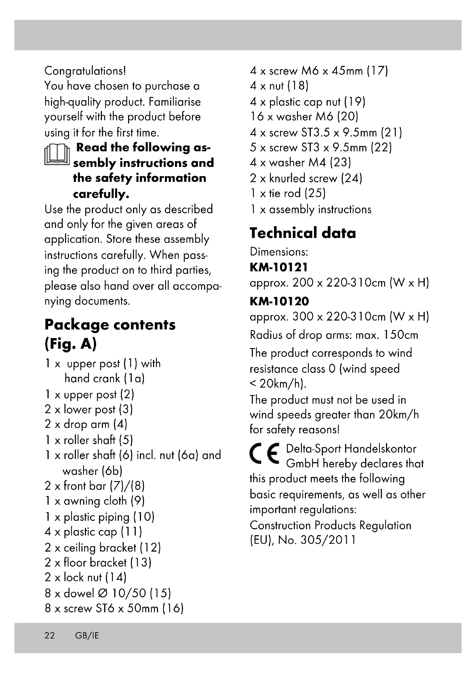
Package contents (Fig. A)
1 x upper post (1) with hand crank (1a)
1 x upper post (2)
2 x lower post (3)
2 x drop arm (4)
1 x roller shaft (5)
1 x roller shaft (6) incl. nut (6a) and washer (6b)
2 x front bar (7)/(8)
1 x awning cloth (9)
1 x plastic piping (10)
4 x plastic cap (11)
2 x ceiling bracket (12)
2 x floor bracket (13)
2 x lock nut (14)
8 x dowel ∅ 10/50 (15)
8 x screw ST6 x 50mm (16)
4 x screw M6 x 45mm (17)
4 x nut (18)
4 x plastic cap nut (19)
16 x washer M6 (20)
4 x screw ST3.5 x 9.5mm (21)
5 x screw ST3 x 9.5mm (22)
4 x washer M4 (23)
2 x knurled screw (24)
1 x tie rod (25)
1 x assembly instructions
Technical data
Dimensions:
KM-10121
approx. 200 x 220-310cm (W x H)
KM-10120
approx. 300 x 220-310cm (W x H)
Radius of drop arms: max. 150cm
The product corresponds to wind resistance class 0 (wind speed < 20km/h).
The product must not be used in wind speeds greater than 20km/h for safety reasons!
CE Delta-Sport Handelskontor GmbH hereby declares that this product meets the following basic requirements, as well as other important regulations:
Construction Products Regulation (EU), No. 305/2011

UK Conformity Assessed
Delta-Sport Handelskontor GmbH hereby declares that this product meets the fol-
lowing basic requirements, as well as other important regulations:
Regulation (EU), No. 305/2011

Date of manufacture
(month/year): 12/2022
Intended use
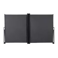
The product is a sun shade designed for outdoor use, such as on balconies or terraces, and manufactured for private use.
The product is not intended for commercial use.
Safety information

Life-threatening hazard!
- Never leave children unattended with the packaging materials.
There is a risk of suffocation. - The product is not a toy or a climbing apparatus!
Ensure that persons, especially children, do not pull themselves up on the product or stand on it. The product can tip over. - The maximum load of the non-retractable parts of the awning must not exceed 15kg!
-
Check the product for damage or wear before each use. Only use the product if it is in perfect condition!
-
Ensure that the plastic caps have no external damage. Defective plastic caps must be replaced.
- When installing on balconies or installation sites not at ground level, the floor and ceiling brackets must be fastened with suitable mounting materials in order to prevent the product from falling.
- Because of the risk of falling, make sure that the person installing the product is sufficiently secured with a harness.
Risk of injury!
- Mind your fingers in particular when retracting and extending the product. There is a risk of injury from crushing.
- The product may only be used under adult supervision and must not be used as a toy.
- Ensure the product is properly stabilised before using it.
- Keep open flames, barbecues, and patio heaters away from the product.
- Check that all parts have been properly assembled before each use.
- Improper installation can impair the product's safety and functionality.
-
The product must not be used in adverse weather conditions such as strong winds, rain or snow.
-
Retract the product if wind speeds higher than 20km/h are expected (strong breeze, larger branches and trees move, and the wind is clearly audible).
- Never use the product as shelter during storms.
- Close the product if the wind picks up or in other adverse weather conditions.
- Before opening or closing the product, ensure that there are no persons or objects in the opening or closing areas.
- The product offers protection from direct sunlight outdoors. Due to reflecting UV radiation, appropriate sunscreen products should still be used.
- Place the product on a flat, level surface.
- Check regularly to make sure all screws are tight!
- The manufacturer accepts no liability for accidents which occur as a result of ignoring the safety information above or due to improper handling.
⚠️ Preventing damage to the product!
- Secure the product during extreme weather conditions, e.g. strong winds. Store the product in a sheltered area.
Important pre-installation information
WARNING! For optimal stability of the product, the floor and ceiling brackets must be firmly screwed in place, especially on balconies or locations not at ground level. If the product is not screwed to the floor and ceiling, the manufacturer is absolved of all liability.
WARNING! Before you begin installing the product, measure the height between the floor and the ceiling.
WARNING! Installing the product requires at least two people due to its size.
WARNING! As tools/machinery need to be used, manual skills are indispensable.
Suitable installation site
For ceiling installation, a concrete ceiling or a load-bearing wooden beam structure is suitable. For floor installation, a concrete foundation or concrete slab of at least 50 x 50 x 5cm (L x W x D) is suitable.
Note: if you attach the product to a wooden beam structure, you must firmly fasten the product to it as wood warps depending on the temperature and humidity. Enquire at a specialist retailer about suitable installation materials.
Note: alternative installation conditions must be checked by a specialist company for their load-bearing capacity and durability.
Suitable installation materials
Before installing the product, the installation material must be determined.
If the installation surface is load-bearing, the appropriate installation materials for fastening the product must be selected.
Fastening materials:
- Dowel ∅ 10/50 (15) and screw ST6 x 50mm (16) for concrete and load-bearing masonry.
- Screw ST6 x 50mm (16) for load-bearing wooden beam structures.
Note: inquire at a specialist retailer about suitable installation materials for the floor and ceiling brackets.
Assembly
To assemble the product you will need the following tools (not included in the package contents): a suitable drill, measuring tape, a cross-head screwdriver, a spanner and a hex key.
WARNING! Because of the risk of falling, make sure that the person installing the product is sufficiently secured with a harness.
Note: for optimal stability of the product, the floor and ceiling brackets must be firmly screwed in place.
Installing the ceiling bracket
Important: both ceiling brackets must be perfectly aligned and have a distance of exactly 190cm (KM-10121) / 290cm (KM-10120) from each other (measured between the inner drill holes of both ceiling brackets) (Fig. E). Place the ceiling bracket (12) in the desired position and mark 2 holes opposite each other with a pencil (Fig. B).
- Using the appropriate tool, drill 2 holes in the marked places. Insert 1 dowel (15) into each hole (Fig. C).
Note: use other dowels and screws if required for the installation surface.
- Place a plastic cap (11) onto each ceiling bracket (12) and insert 2 screws (16) through each washer (20) (Fig. D).
- Mount the ceiling bracket onto the ceiling.
- Mount the second ceiling bracket as described in steps 1–3.
Installing the floor bracket
- Plumb the exact position of the floor bracket (13) with a cord (not included in the package contents). Mark the correct places and, using a pencil, mark 2 holes opposite each other (Fig. F).
Note: the floor bracket (13) must be positioned perpendicular to the ceiling bracket (12).
- Using the appropriate tool, drill 2 holes in the marked places. Insert 1 dowel (15) into each hole (Fig. G).
Note: if necessary, use other dowels and screws if required for the mounting surface.
-
Place a plastic cap (11) onto each floor bracket (13) and insert 2 screws (16) through each washer (20) (Fig. H).
-
Mount the floor bracket onto the floor.
-
Mount the second floor bracket as described in steps 1-4.
Important: the floor brackets must be perfectly aligned and have a distance of exactly 190cm (KM-10121) / 290cm (KM-10120) from each other (measured between the inner drill holes of both floor brackets).
Installing the posts (Fig. I)
There are 18 adjustment options for setting the correct length of the posts.
- Connect each upper (1)/(2) and lower post (3) at the appropriate length.
- Fasten each upper (1)/(2) and lower post (3) with 2 screws (17) and washers (20). Fasten each screw (17) with a nut (18) and washer (20). Then place a plastic cap (19) on each nut.
Installing the awning frame
- Slot both drive shaft poles (5)/(6) together (Fig. J).
- Fasten the drive shaft (5 + 6) with 4 screws (22).
- Slot both front bars (7)/(8) together (Fig. J). The locking button must visibly and audibly click into place.
- Run the plastic piping (10) through the narrower tunnel of the awning cloth (9).
- Insert the awning cloth with plastic piping into the drive shaft (5 + 6) as shown.
Note: make sure that the bottom fold of the tunnel (front bar tunnel) is always facing upward during installation.
- Insert the front bar (7 + 8) into the front bar tunnel in the awning cloth (9).
- Place the end of the roller shaft (5) on the catch (2a) of the post (2) (Fig. K).
Note: the catch (2a) must be completely inside the roller shaft (5).
- Remove the pre-mounted nut (6a) and washer (6b) from the roller shaft (6).
- Insert the end of the roller shaft (6) into the post (1). Use the nut (6a) and washer (6b) to fasten it (Fig. K).
Note: make sure that the bolt on the roller shaft (6) is properly aligned.
- Fasten the roller shaft (5) with 1 screw (22) (Fig. K).
Fastening the awning frame in the bracket
Important: assembling the product requires at least two people due to its size.
- First insert the awning frame into the ceiling brackets (Fig. L).
- Place the lock nut (14) onto the threaded spindle (3a) (Fig. M).
- Insert the tie rod (25) through the hole in the threaded spindle (3a) and turn it to change the height of the post (Fig. M).
Note: please note the maximum extension length (max. 5cm) of the threaded spindle (3a).
- Turn the lock nut (14) in the floor bracket (13) to fasten the threaded spindle (Fig. M).
Note: please note that the threaded spindle (3a) may only be unscrewed by no more than 5cm (Fig. M).
- Finally, fasten the posts on each ceiling bracket with 2 screws (21) and washers (23) (Fig. N).
Note: for easier installation, drill two holes into each ceiling bracket before fastening the posts.
Installing the drop arms and front bar
- Unscrew the knurled screw (4a), the corresponding nut (4b) and the drop arm bracket (4c) from each drop arm (4).
- Place the drop arm bracket (4c) on a post (1/2) (Fig. O).
Note: ensure that both drop arm brackets (4c) are fixed at the same height on the posts (approx. 40cm from the bottom edge of the upper post to the bottom edge of the drop arm bracket).
- Tightly screw the drop arms back into each drop arm bracket (4c) with the knurled screws (4a) and the corresponding nuts (4b).
Note: the knurled screw (4a) points outwards.
- Fasten each drop arm (4) onto the front bar (7 + 8) with the knurled screws (24) (Fig. P).
Use (Fig. Q)
- Hook the hand crank (1a) into the crank lug (1b) of the upper post (1).
-
Turn the hand crank (1a) to open or close the product.
-
Remove the hand crank (1a) after each use and store it in a secure location.
Storage, cleaning
When not in use, always store the product clean and dry at room temperature.
Clean only with water and wipe dry afterwards with a cloth.
IMPORTANT! Never clean the product with harsh cleaning agents. Leave the product open to dry.
Disposal

Dispose of the product and packaging materials in accordance with current local regulations. Store the packaging materials (foil bags, for example) out of the reach of children. For further information about disposal of the product no longer needed, contact your local council. Dispose of the product and the packaging in an environmentally friendly manner.

The Recycling Code distinguishes different materials to be returned for recycling. The
Code consists of the recycling symbol for the recycling process and a number that identifies the material.
Notes on the guarantee and service handling
The product was produced with great care and under continuous quality control. DELTA-SPORT HAN-DELSKONTOR GmbH gives private end customers a three-year guarantee on this product from the date of purchase (guarantee period) in accordance with the following provisions. The guarantee is only valid for material and manufacturing defects. The guarantee does not cover parts subject to normal wear and tear that are thus considered wear parts (e.g. batteries) or fragile parts such as switches, rechargeable batteries, or parts made of glass.
Claims under this guarantee are excluded if the product has been used incorrectly, improperly, or contrary to the intended purpose, or if the provisions in the instructions for use were not observed, unless the end customer proves that a material or manufacturing defect exists that was not caused by one of the aforementioned circumstances.
Claims under the guarantee can only be made within the guarantee period by presenting the original sales receipt. Please therefore keep the original sales receipt.
The guarantee period is not extended by any repairs carried out under the guarantee, under statutory guarantees, or as a gesture of goodwill. This also applies to replaced and repaired parts.
If you wish to make a claim please first contact the service hotline mentioned below or contact us by e-mail. If there is a guarantee case, then the product will be repaired or replaced free of charge to you or the purchase price will be refunded, depending on our choice.
Your legal rights, in particular guarantee claims against the respective seller, are not limited by this guarantee.
IAN: 409406_2207
IAN: 409416_2207
GB Service Great Britain
Tel.: 0800 404 7657
E-Mail: deltasport@lidl.co.uk
IE Service Ireland
Tel.: 1800 101010
E-Mail: deltasport@lidl.ie
Félicitations !