RS185 - Irrigation timer MESTO - Free user manual and instructions
Find the device manual for free RS185 MESTO in PDF.

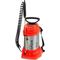
| Product type | Backpack sprayer |
| Brand | MESTO |
| Model | RS185 |
| Max. filling capacity | 18 liters |
| Max. spray pressure | 6 bar |
| Max. service temperature | 40 °C |
| Empty weight | 4.8 kg |
| Max. total weight | 22.8 kg |
| Tank material | Polypropylene |
| Residual quantity | < 0.27 liters |
| Max. flow rate | 1.4 l/min at 6 bar |
| Transport mode | On the back |
| Main functions | Spraying of plant protection products, herbicides, cleaning and disinfection products |
| Maintenance and cleaning | Clean the nozzle and filter with running water; grease the sleeve and pump rod after 50 uses or at least once a year |
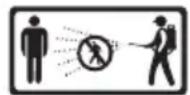
| Safety | Wear protective equipment; never spray towards people, animals, power lines; avoid sources of ignition |
| Spare parts and repairability | Use only MESTO spare parts; serviceable: suction valve, compression valve, sleeve, O-rings |
| Warranty | Up to 3 years according to legal obligation, excluding wear parts |
Frequently Asked Questions - RS185 MESTO
User questions about RS185 MESTO
0 question about this device. Answer the ones you know or ask your own.
Ask a new question about this device
Download the instructions for your Irrigation timer in PDF format for free! Find your manual RS185 - MESTO and take your electronic device back in hand. On this page are published all the documents necessary for the use of your device. RS185 by MESTO.
USER MANUAL RS185 MESTO
RS120, RS125, RS180, RS185


D A CH
Instructions for Use 14
F CH B NL CDN
Mode d'emploi 22
NL B
Welcome and congratulations
for purchasing your new backpack spraying device. Thank you for the trust you have shown in our brand.
Your satisfaction with our products and services is very important to us.
Please contact us if your expectations are not met.
You will find our address on the title page of these instructions for use.

Make certain to read the instructions for use before using the device! Keep the instructions for use in a safe place where they can be easily found. Particular safety measures are required when working with the device.
Usage
The backpack spraying device is designed for the spraying of plant protection products, including weed killers in the stipulated concentrations, as well as cleaning agents, disinfectants and construction chemicals. The spray product manufacturer has to approve that they can be applied with spraying devices. Nitric acid, acetic acid and propionic acid must only be used in a concentration of up to 10%, phosphoric acid and sulfuric acid in a concentration of up to 30%, and potassium hydroxide solution and caustic soda in a concentration of up to 20%.
Follow the instructions of the spray product manufacturers before each application. The backpack spraying device may be used outdoors or in well ventilated rooms only.
Have the salesperson or an expert show you how to operate the device if you are working with it for the first time.
At the time of manufacture, there are no known harmful effects to the device caused by plant protection products approved by the Federal Office of Consumer Protection and Food Safety.

Improper use may result in dangerous injuries and environmental damage.
You should only use other products if harmful effects on the device and endangerment of people and the environment can be excluded. Upon request, we will provide you with a list of active ingredients used in the spraying device.
Not suitable for
- inflammable liquids
• corrosive substances (certain disinfecting and impregnating agents, acids and bases)
• Liquids containing ammonia
• liquids at temperatures above 40 °C (104°F)
• solvents and liquids containing solvents
• viscous or sticky liquids or liquids that form residues (dyes, greases) - use in applications for foodstuffs.
Under no circumstances should you use
- external pressure sources without original compressed air valve
- for flaming
• for storing and holding liquids - as an eyewash.
Safety

Only trained, healthy and rested people may work with the device.
You should not be under the influence of alcohol, drugs or medication. Children and adolescents must not use the device. Keep the spraying devices out of the reach of children.
Keep bystanders away during spraying. Take precautions to prevent hazardous substances from being misused.

Wear suitable protective clothing, goggles and respiratory protection when working with hazardous substances.

Never spray on people, animals, electrical devices and lines, into the wind, or into bodies of water.

Avoid ignition sources in the environment.

Do not leave the device in the sun. Ensure that the device is not heated beyond the maximum operating temperature ( Table 1). Protect the device from frost and ammonia.

Never blow through the nozzles or valves with your mouth.

There is a risk of slipping or tripping on smooth or wet surfaces, snow, ice, on slopes and on uneven terrain.

Repairs and modifications to the tank are not permitted.

Use only MESTO spare parts and accessories.
We cannot assume any liability resulting from the use of third-party parts.

When pumping, always observe the pressure gauge to ensure that the recommended spraying pressure is maintained ( Table 1 below).
After use and before maintenance work, depressurize the device.

Transport the devices in such a way that they are protected against damage and overturning.
I can will find the illustrations referred to above in the pages 3 – 5 of these instructions for use.
Scope of delivery
Carrying strap [1], tank [2], carrying handle [3] (for 18 liter devices only), small parts kit [4], instructions for use [5], hose [6], spray wand [7], shut-off valve [8], back cushion or hip belt with back cushion [9] (not for all models), pump lever [10] and handle [11]. (Figs. 1a and 1b)
| GB | IRL | AUS | USA | NZ | CDN | IND |
Technical data
| Type of device RS120 RS125 RS180 RS185 | |||
| Max. filling amount 12 liters (3.17 US gallons) 18 liters (4.76 US gallons) | |||
| Max. spraying pressure 6 bar | |||
| Max. operating temperature 40 °C | |||
| Net weight 4.5 kg (9.92 lbs) | 4.8 kg (10.58 lbs) | ||
| Gross weight max. | 16.5 kg (9.92 lbs) | 22.8 kg (50.27 lbs) | |
| Tank material | Polypropylene | ||
| Where device is carried Back | |||
| Technical residual quantity | < 0.25 liters(0.07 US gallons) | < 0.27 liters(0.07 US gallons) | |
| Max. volume flow | 1.4 l/min (0.53 gal/min) at 6 bar | ||
Table 1
Assembly
- Fasten the carrying strap [1] to the tank. Secure it with the metal pin [12]. (Fig. 2)
- Attach the eyes [13] on the carrying strap [1] to both sides of the tank.
- Attach the back cushion [9] to the tank using 2 bolts (outside) and 2 nuts with washers (inside) [2]. (Figs. 2 and 3)
- Press the 2 nuts [14] into the carrying handle [3] (for 18 liter devices only). Insert the carrying handle and screw tight with the 2 screws [15] in the tank [2]. (Fig. 3)
- Feed the hose [6] through the opening in the lower part of the tank as well as between the shaft [16] and tank base. Push the hose all the way onto the connecting piece [17]. Tighten the union nut to secure the hose. (Fig. 4)
- Push the hose [6] all the way onto the connecting piece of the shut-off valve [8]. Tighten the union nut to secure the hose. (Fig. 4)
- Screw the spray wand [7] onto the shut-off valve [8]. (Fig. 4)
- Turn the shaft [16] clockwise until it engages. Insert the pump lever [10] to the required depth into the shaft [16] (3 positions). (Fig. 5)
Rump lever [10] with handle can be fitted on the left or right. - Secure the pump lever [10] in the shaft using the retaining clip [18]. (Fig. 5)
- Push the handle [11] to the required position (A, B, C) into the pump lever [10]. (Fig. 5)
Ensure that the handle is locked in place in the pump lever.
Checks
Visual inspection:
- Are tank [2], hose [6], shut-off valve [8] with pressure gauge [22] and spray wand [7] with nozzle [41] undamaged?
May special attention to the connections between the tank [17] – hose [6] and the hose [6] – shut-off valve [8] and to the condition of the spray wand [7].
Function:
- Activate the pump lever [11]. (Fig. 8)
▶ Increasing pressure is indicated on the pressure gauge [22]. (Figs. 8 and 9)
The wheel lock [23] can be used to lock and unlock the lever on the shut-off valve [8]. Locking the lever [23b] prevents unintentional spraying.
- Unlock the wheel lock [23a] and activate the shut-off valve [8]. (Fig. 9)
▶ The shut-off valve must open and close.
| GB IRL | AUS USA | NZ CDN | IND |

Have damaged parts or parts that do not work properly repaired immediately by our customer service department or by service partners authorized by us.
Preparation

Observe the instructions in the section entitled „Safety“.
The device must be in an upright position.
If filling the tank from a water line, ensure that the line or a hose does not project into the tank.
- Screw the cover [19] off the tank. (Fig. 6)
Measuring cups [20] are integrated in the cover [19] and can be used to prepare the spraying agent. Fill the tank 1/3 with water, pour in the spraying agent and then fill up with water.
- Pour the spray liquid through the filling strainer [21] into the tank. (Fig. 7)
In the case of 18 liter devices the maximum filling quantity is reached as soon as the liquid level can be seen in the filling strainer.
- Screw the cover [19] onto the tank. (Fig. 6)
Spraying

Observe the instructions in the section entitled "Safety".
Operate the device only while it is vertical or suspended upright and nearly vertical.
Avoid allowing drops of spray to drift onto areas that are not being treated.
Observe the instructions of the spray product manufacturer!
-
Place the device on its back. (Fig. 8)
-
Using the pump lever [11], pump slowly and regularly to maintain a continuous spraying pressure. (→ Table 2, Fig. 8)
Max. pressure should not exceed 6 bar. If the maximum pressure is exceeded, the pressure relief valve will actuate and release the excess pressure from the pressure vessel.
To prevent dripping, hold the spray wand up when first spraying and activate the shut-off valve until no more liquid mixed with air comes out of the nozzle.
- Ensure that the optimum spraying pressure is set on the pressure gauge [22] (Figs. 8 and 9).
| NozzlePressure | 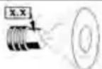 |  | |
| 1.1 (Basic equipment) 80015 8002 | |||
| Flow rate in l/min | |||
| 2.0 bar 0.56 0.48 0.65 | |||
| 6.0 bar 0.96 0.85 1.13 | |||
Table 2. Dependence: Spraying rate – spraying pressure
Liquid mixed with air emerges from the nozzle, the tank is empty. Pump the device completely empty after each fifth filling at the latest.
After Usage

Observe the instructions in the section entitled "Safety". Never leave liquid in the device.
- Activate the shut-off valve [8] until the spray line is depressurized.
- Screw the cover [19] off the tank. (Fig. 6)
- Dilute the remaining quantity twice in a row with 1/2 liter of water each time and spray the resulting liquid onto the treated area.

Collect and dispose of the residual liquid according to all applicable laws, requirements and regulations. Observe the instructions of the spray product manufacturer!
- Wipe off the device with a moist cloth.
- For drying and storing the device, remove the cover and keep the device in a dry place protected from sunlight and freezing temperatures.

Clean the protective equipment and yourself every time after usage.
Care and maintenance

Observe the instructions in the section entitled "Safety".
After using the device 50 times or if the device malfunctions, at least once a year, preferably after the winter break:
- Grease the diaphragm [24]. (Fig. 10)
- Oil the pump rod [33]. (Fig. 20)
- Grease the bearings on the shaft [16]. (Fig. 12)
- Clean the nozzle [41] and the insert [40] under running water. If required use a brush. (Fig. 18)
- Clean the filter [38] under running water. (Fig. 17) (→ „Disassembling the shut-off valve“)

Observe the legal requirements of your country for accident prevention and check the device in regular intervals. Unless otherwise specified, we recommend that an expert carries out an external test every 2 years and an internal test every 5 years as well as a strength test every 10 years.
Maintaining the intake valve
- Press the catch [25] out of the notch. Screw the cylinder [27] out of the tank. (Fig. 10)
-
Clean and, if required, replace the valve disc [28]. (Fig. 11)
When replacing the valve disc, insert the new valve disc [28] and press and turn it into the opening, using a wooden object (e.g. hammer shaft). (Fig. 11)
Isseal the tank, ensure that the O-ring [26] is correctly positioned. (Fig. 10)
To prevent damage to the diaphragm [24], carefully insert the cylinder [27]. (Fig. 10) -
Screw in the cylinder [27] until the catch [25] engages in the first tooth of the notch. (Fig. 10)
Maintaining the pressure valve
- Press the catch [25] out of the notch. Screw the cylinder [27] out of the tank. (Figs. 10 and 13)
-
Remove the pressure vessel [34]:
a) Remove the fixing [30] and cap [29]. (Fig. 12)
b) Remove the U-bolt [32]. (Fig. 12)
c) Pull the pressure vessel [34] half out of the tank. (Fig. 13)
d) Using the filling strainer [21], unscrew the pressure valve screw [35]. (Fig. 14) -
Clean and, if required, replace the pressure valve disc [28]. (Fig. 14)
-
Clean and, if required, replace the diaphragm [24]. (Fig. 14)
Removing the shaft and pull rod
- Remove the retaining clip [18]. (Fig. 15)
- Pull the pump lever [10] and handle [11] out of the shaft [16]. (Fig. 15)
- Remove the fixing [30] and the cap [29]. (Fig. 16)
- Detach the pull rod [31] from the pump rod [33].
- Pull the shaft [16] and pull rod [31] out of the tank. (Fig. 16)
- Remove the lock washer [36] and the bolt [37].
- Separate the pull rod [31] from the shaft [16]. (Fig. 16)
Replacing the O-ring on the pump rod
- Remove the fixing [30] and cap [29]. (Fig. 12)
- Detach the pull rod [31] from the pump rod [33]. (Fig. 12)
- Using a spark plug wrench, unscrew the guide bush [49]. (Fig. 21)
- Replace the O-ring [50]. (Fig. 21)
Disassembling the shut-off valve
- Unscrew the handgrip [39] from the shut-off valve. (Fig. 19)
- Unscrew the adapter [42].
- Pull off the ring [43]. (Fig. 19)
- Loosen the 4 screws and pull the half shells [44] apart.
- Unscrew the locking cap [45] from the valve body [48].
- Pull the pressure bolt [46] out of the valve body [48]. (Fig. 19)
Faults

Use only original spare and accessory parts.
| Fault Cause Remedy | ||
| No pressure builds up in the device. Pump lever with handle [11] can be moved very easily. | Diaphragm [24] is defective. | Replace the diaphragm. (Fig. 14) |
| Foreign object prevents the valve disc [28] from closing | Clean intake or pressure valve (Figs. 11 and 14) | |
| Valve disc [28] of the intake or pressure valve defective. | Replace valve disc. (Figs. 11 and 14) | |
| Pump lever with handle [11] is pulled downwards. | Intake valve [27] sticking. | Clean intake valve. (Fig. 11) |
| Pump lever with handle [11] is pulled upwards. | Foreign object prevents closure of the pressure valve [35] or defective valve disc [28]. | Clean pressure valve or replace valve disc. (Fig. 14) |
| Pump lever with handle [11] locked or can be moved downwards with difficulty only. | Diaphragm [24] and/or guide bush [49] not lubricated. | Lubricate diaphragm and/or guide bush (Figs. 10, 20) |
| Pressure valve [35] dirty. | Clean pressure valve. (Fig. 14) | |
| Filter [38] and / or nozzle [41] blocked. | Clean filter (Fig. 17) and / or nozzle (Fig. 18). | |
| Only a jet emerges, there is no atomization. | Nozzle insert [40] is missing. | Position the insert in the nozzle. (Fig. 18) |
| Nozzle [41] dirty. Clean nozzle (Fig. 18) | ||
| Liquid dripping from the nozzle. | Foreign object in the nozzle [41] or / and the insert [40]. | Clean nozzle and / or insert. |
| Device sprays only when pumped. | Pressure vessel [34] completely filled with liquid. | Pump device completely empty. Repeat after 5 fillings at the latest. |
| The shut-off valve does not close. Liquid comes out without the pump lever being activated. | O-ring [47] of the pressure bolt [46] not greased. O-ring [47] defective. | Grease the O-ring of the pressure bolt. (Fig. 19) Replace pressure bolt or O-ring. (→ „Disassembling the shut-off valve“) |
Contact address for additional information → see title page.
Warranty
We guarantee that from the time it is first purchased for a period of the legally valid required warranty period (maximum 3 years) this device will not exhibit any material or processing errors. If defects are discovered during the warranty period, the manufacturer or the distributor in your country will repair the device without charging for the labor or material or (at the discretion of the manufacturer) replace the device itself or its defective parts. If such defects are discovered, please contact us immediately. We require the invoice or cash register receipt for purchase of the device. The warranty does not include wearing parts (seals, O-rings, diaphragm, etc.) or defects, which have occurred due to improper use or unforeseeable circumstances.
CE Declaration of Conformity
In accordance with EC Directive 2006/42/EC, Annex II, No. 1A.
Applicable standards:
DIN EN ISO 19932-1: 2013
DIN EN ISO 19932-2: 2013
We,
declare under our sole responsibility that the devices of the series RS120, RS125, RS180, RS185, as supplied, meet all the relevant requirements of Directive 2006/42/EC.
Rolf Rehkugler, Ludwigsburger Straße 71, D-71691 Freiberg is authorized to compile the technical documentation.