Solo 6240 - Saw AL-KO - Free user manual and instructions
Find the device manual for free Solo 6240 AL-KO in PDF.
User questions about Solo 6240 AL-KO
0 question about this device. Answer the ones you know or ask your own.
Ask a new question about this device
Download the instructions for your Saw in PDF format for free! Find your manual Solo 6240 - AL-KO and take your electronic device back in hand. On this page are published all the documents necessary for the use of your device. Solo 6240 by AL-KO.
USER MANUAL Solo 6240 AL-KO
natural_image
Technical line drawing of a chain-linking device with visible gears and blades (no text or symbols)DE
EN
NL
FR
IT
SL
HR
PL
CS
SK
HU
DA
SV
NO
FI
ET
LT
LV
RU
UK
TR


Inhaltsverzeichnis
EN Translation of the original operating instructions.... 26
AL-KO KOBER GROUP Kötz, Germany
This documentation or excerpts therefrom may not be reproduced or disclosed to third parties without the express permission of the AL-KO KOBER GROUP.
text_image
Technical diagram of a chain-linking device with numbered parts for identificationtext_image
(11) (13)natural_image
Illustration of a hand using a chain-linking tool to lift a tree branch (no text or symbols)natural_image
Illustration of a fuel being poured into a gas cylinder with an oil pump icon (no text or symbols)KRAFTSTOFF
natural_image
Illustration of a no-smoking cigarette crossed out of a campfire (no text or symbols)
WARNUNG!
text_image
chain oil
text_image
Technical diagram of a tracked vehicle with labeled parts 1 and 2
natural_image
Technical diagram of a mechanical assembly with no visible text or symbols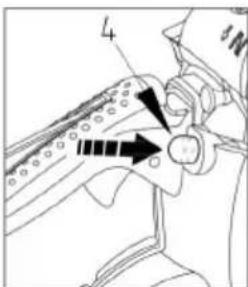
text_image
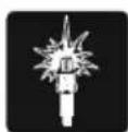
4
text_image
5
natural_image
Line drawing of a person's legs and feet wearing athletic shoes (no text or symbols)
natural_image
Technical line drawing of a mechanical device with directional arrows indicating motion (no text or symbols)natural_image
Line drawing of a person using a bicycle pedal device (no text or symbols)
WARNUNG!
natural_image
Line drawing of a hand using a tool to lift a tree stump (no text or symbols)ÖLVERSORGUNG PRÜFEN
natural_image
Line drawing of a hand using a tool to adjust or install a mechanical component (no text or symbols present)natural_image
Illustration of a person using a chainsaw to cut tree bark (no text or symbols)
text_image
(a) (1) (2)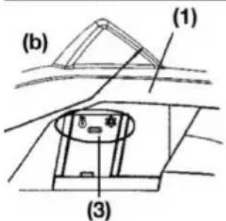
text_image
(b) (1) (3)
text_image
(1) (2) (3)
WARNUNG!
VERGASER-FROSTSCHUTZ
natural_image
Prohibition sign showing a diagonal slash over a pipe, crossed out by a diagonal line (no text or symbols)
WARNUNG!
natural_image
Illustration of a hand using a tool to cut a circular object with a curved arrow indicating rotation (no text or symbols)natural_image
Illustration of a person using a sawtooth to cut a circular object with a curved arrow indicating rotation (no text or symbols)natural_image
Illustration of a hand using a tool to cut a ball on a rolling surface, with an arrow indicating motion (no text or symbols)natural_image
Pure mechanical component diagram without any text, numbers, or symbols(A) Fallkerb
(B) Fällschnitt
natural_image
Simple line drawing of a ground surface with a downward arrow indicating a point of interest (no text or symbols)natural_image
Simple line drawing of a log with arrows indicating direction and a small house symbol at the base (no text or labels)text_image
Diagram illustrating a physics experiment with a cart, moving a wooden log, and labeled points (0 and 1) indicating positions.text_image
Diagram illustrating airflow around a cylindrical object with labeled parts ① and ②, showing directional arrows.
text_image
Diagram showing two labeled arrows pointing to a pipe or channel with annotations ① and ②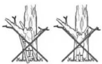
natural_image
Two hand-drawn diagrams showing tree branches with leaves and a ladder, no text or symbols presentnatural_image
Exploded view diagram of a mechanical device showing internal components and housing (no text or labels)
WARNUNG!
natural_image
Hand holding a small object with a spiral arrow, no visible text or symbolsnatural_image
Technical line drawing of a mechanical device with gears and levers (no text or symbols)2. Ölanschluss
natural_image
Illustration of a hand holding a tool with a labeled component (1), no text or symbols presentnatural_image
Technical line drawing of a car engine bay with visible internal components (no text or symbols)natural_image
Line drawing of a tracked robot with visible gears and control panel (no text or symbols)2. Kraftstofffilter
natural_image
Simple line drawing of a hand holding a tool above a rock, no text or symbols present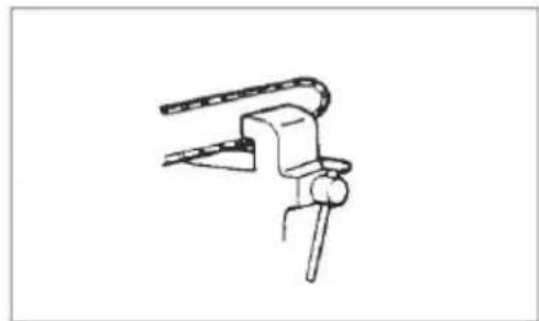
natural_image
Simple line drawing of a mechanical clamp or bracket assembly (no text or symbols)Sägekette

WARNUNG!
Intended / not intended use....27
Remainder driven....27
Parts location....28
Symbols on the machine....29
For safe operation....31
Installing guide bar and saw chain....33
Fuel and chain oil....34
Operation....36
Sawing....39
Maintenance....41
Maintenance of Saw Chain and Guide Bar....43
Storage....45
Waste disposal and environmental protection....45
Troubleshooting guide....45
Specifications....47
Warranty....48
EC declaration of conformity....48

CAUTION!
Before using our products, please read this manual carefully to understand the proper use of your unit.
Keep this manual handy.

CAUTION!
Instructions contained in warnings within this manual marked with a symbol concern critical points which must be taken into consideration to prevent possible serious bodily injury, and for this reason you are requested to read all such instructions carefully and follow them without fail.

CAUTION!
This mark indicates instructions which must be followed in order to prevent accidents which could lead to serious bodily injury or death.

CAUTION!
This mark indicates instructions which must be followed, or it leads to mechanical failure, breakdown, or damage.

CAUTION!
Read these notes before you start working with the saw and keep them.
Read the instructions carefully. Familiarise with the control elements so that you are able to safely operate the device. Always keep these Operating Instructions together with the chain saw.

CAUTION!
Risk of hearing defects!
Under normal operating conditions, this device can expose the operator to a noise level of 80 dB(A) or more.
The chain-saw shall be held with the right hand on the rear handle and the left hand on the front handle.

CAUTION!
Noise protection!
Please observe the local regulations when operating your device.
INTENDED / NOT INTENDED USE
The chain saw serves trunks, square timbers and for cutting branches, according to the available cutting length. Only materials from wood may be worked on. Sufficient personal protection equipment (PPE) is required according to the operating instructions during the use. This product is not designed for use by a trained operator for pruning and dismantling standing tree crowns. For damage or injuries which resulting from misapplication are responsible by the user/operator and not the manufacturer. Suitable sawing chains, guide bars combinations may be used as mentioned in the operating instructions only for the machine. A component of the intended use is also the attention of the safety references, as well as the operating instructions in the operating instructions. Persons, who serve the machine, must make themselves trained and familiar with this product and think over all the possible dangers. Beyond that the valid rules for the prevention of accidents are to be kept in every detail. Other general rules within ranges according to industrial medicine and in terms of safety are to be considered. Changes in the machine completely exclude an support of the manufacturer and from it developing damage and lead to expiring the warranty. This equipment is designed for use in home garden.

WARNING!
Please observe the national regulations for the use of chain saws! (Work safety, environment)
REMAINDER DRIVEN
Also when appropriate using the tool always remains a certain residual risk, which cannot be excluded. From the kind and construction of the tool the following potential endangerments can be derived:
■ Contact with the unprotected sawing chain (cuts)
■ Unexpected, sudden movement of the sawing sword (cuts)
■ Damage of the ears, if no prescribed protection of the ears is carried
Inhale from poisonous particle, exhaust gases of the combustion engine
■ Contact of gasoline on the skin
Noise. A degree of noise from the machine is not avoidable. Route noisy work is to be licensed and limits for certain periods. Keep rest periods and they may need to restrict the working hours to a minimum. For their personal protection and protection of people working nearby, an appropriate hearing protection shall be worn
Vibration. Warning: The actual existing vibration emission value during use of the machine can deviate from the manual or the manufacturer specified. This can be caused by the following factors, before or during each of use should be considered:
If the machine is used correctly
If the method of cutting the material and how it is processed correctly
The use of the machine state is in the regulatory
■ Sharpness condition of cutting tool or cutting tool real
The grab handles are mounted back to optional vibration handles and are they fixed to the machine body.
If you notice an unpleasant sensation or skin discoloration during use of the machine on your hands once you stop working. Place an adequate work breaks. In disregard of adequate work breaks, there may be a hand-arm vibration syndrome.
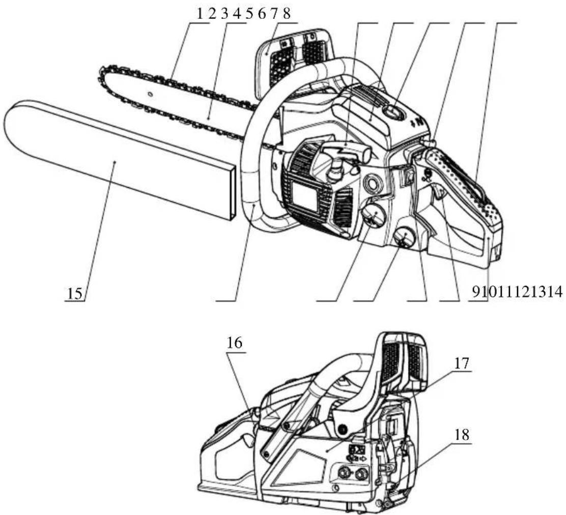
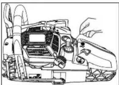
PARTS LOCATION
text_image
1 2 3 4 5 6 7 8 15 91011121314 16 17 18| 1 | Saw chain | 10 | Throttle trigger |
| 2 | Guide bar | 11 | Engine switch |
| 3 | Front hand guard | 12 | Oil tank |
| 4 | Starter handle | 13 | Fuel tank |
| 5 | Air filter cover | 14 | Front handle |
| 6 Lock nut 15 Guide bar cover | ||
| 7 Choke knob 16 Primer bulb | ||
| 8 Throttle trigger lock lever 17 Clutch cover | ||
| 9 Rear handle 18 Spiked bumper |
SYMBOLS ON THE MACHINE
 | Read, understand and follow all warnings. |
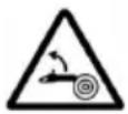 | Warning! Danger of kickback. Beware of chain saw kickback and avoid contact with bar tip. |
 | Do not use chain saw one-handed. |
 | Always use chain saw two-handed. |
 | Appropriate ear, eye, and head protection must be worn |
 | Read operator's instruction book before operating this machine. |
 | Always wear safety and anti-vibration(AV) gloves when operating the device. |
 | Always wear safety and slip-resistant boots when operating the device. |
For safe operation and maintenance, symbols are carved in relief on the machine. According to these indications, please be careful not to make any mistake.
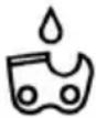 | The port to refuel the chain oilPosition: near the oil cap |
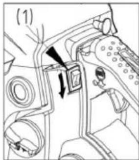
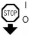 | Operate the engine switch Flipping the switch to the "O" position, immediately the engine stops.Position: rear at the left side of the rear handle |
 | Operate the choke knob Pull out the choke knob, close the choke; push in the choke knob, open the choke.Position: Air filter cover |
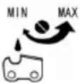 | Adjust the oil pump If you turn the rod by screwdriver follow the arrow to the "MAX" position, the chain oil flow more, and if you turn to the "MIN" position, less.Position: Bottom of the power unit |
 | The screw under the "H" stamp is The High-speed mixture adjustment screw.Position: upper-left of the rear handle |
 | The screw under the "L" stamp is The Slow-speed mixture adjustment screwPosition: upper-left of the rear handle |
 | The screw up the "T" stamp is the idle speed adjustment screw.Position: upper-left of the rear handle |
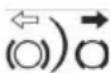 | Shows the directions that the chain brake is released (white arrow) and activated (black arrow).Position: Front of the guide rail |
 | Shows the direction of the saw chain installation.Position: Front of the guide rail |
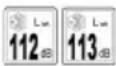 | Guaranteed sound power level:- 112 dB for 6238- 113 dB for 6240 |
 | Engine manual start |
FOR SAFE OPERATION
■ Before operate the product
Before using our products, please read this manual carefully to understand the proper use of your unit.
Never operate a chain saw when you are fatigued, ill, or upset, or under the influence of medication that may make you drowsy, or if you are under the influence of alcohol or drugs.
- Operate the chain saw only in well ventilated areas. Never start or run the engine inside a closed room or building. Exhaust fumes contain dangerous carbon monoxide.
■ Never cut in high wind, bad weather, when visibility is poor or in very high or low temperatures. Always check the tree for dead branches which could fall during the felling operation.
Use safety and slip-resistant footwear, snug fitting clothing and eye, hearing and head protection devices. Use the anti-vibration(AV) glove. It is believed that a condition called Raynaud's phenomenon, which affects the fingers of certain individuals may be brought about by exposure to vibration and cold. Loss of color and numbness in the fingers. The following precautions are strongly recommended because the minimum exposure which might trigger the ailment is unknown. Keep your body warm, especially the head, neck, feet, ankles, hands and wrists. Maintain good blood circulation by performing vigorous arm exercises during frequent work breaks and also by not smoking. Keep the saw chain sharp and the saw, including the AV system, well maintained. A dull chain will increase cutting time, and pressing a dull chain through wood will increase the vibrations transmitted to your hands. A saw with loose components or with damaged or worn AV buffers will also tend to have higher vibration levels. Limit the hours of operation. All the above mentioned precautions do not guarantee that you will not sustain white finger disease or carpal tunnel syndrome. Therefore, continual and regular users should monitor closely the condition of their hands fingers. If any of the above symptoms appear, seek medical advice immediately.
Always use caution when handling fuel. Wipe up all spills and then move the chain saw at least ten (10) feet three (3m) from the fueling point before starting the engine.
Eliminate all sources of sparks or flame (ie. smoking, open flames, or work that can cause sparks) in the areas where fuel is mixed, poured, or stored. Do not smoke while handling fuel or while operating the chain saw.
Do not allow other persons to be near the chain saw when starting the engine or cutting a wood. Keep bystanders and animals out of the work area. Children, pets, and bystanders should be a minimum of 30 feet (10m) away when you start or operate the chain saw.
Never start cutting until you have a clear work area, secure footing, and planned retreat path from the falling tree.
Always hold the chain saw firmly with both hands when the engine is running. Use a firm grip with thumb and fingers encircling the chain saw handles.
- Keep all parts of your body away from the saw chain when the engine is running. Before you start the engine, make sure the saw chain is not contacting anything.
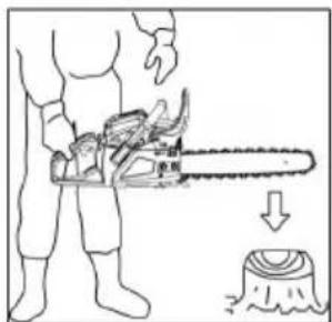
■ Always carry the chain saw with the engine stopped, the guide bar and saw chain to the rear, and the muffler away from your body.
Always inspect the chain saw before each use for worn, loose, or changed parts. Never operate a chain saw that is damaged, improperly adjusted, or is not completely and securely assembled. Be sure that the saw chain stops moving when the throttle control trigger is released.
All chain saw service, other than the items listed in the Operator's Manual, should be performed by competent chain saw service personnel. (e.g., if improper tools are used to remove the flywheel, or if an improper tool is used to hold the flywheel in order to remove the clutch, structural damage to the flywheel could occur which could subsequently cause the flywheel to disintegrate).
■ Always shut off the engine before setting it down.
Use extreme caution when cutting small size brush and saplings because slender material may catch the saw chain and be whipped toward you or pull you off balance.
When cutting a limb that is under tension, be alert for spring back so that you will not be struck when the tension in the wood fibers is released.
- Keep the handles dry, clean and free of oil or fuel mixture.
Guard against kickback. Kickback is the upward motion of the guide bar which occurs when the saw chain at the nose of the guide bar contacts an object. Kickback can lead to dangerous loss of control of the chain saw.
When transporting your chain saw, make sure the appropriate guide bar cover is in place. Securely place the machine during transport to prevent loss of fuel, damage or injury.
- Kickback Safety precautions for Chain Saw Users

WARNING!
Kickback may occur when the nose or tip of the guide bar touches an object, or when the wood closes in and pinches the saw chain in the cut.

Tip contact in some cases may cause a lightning fast reverse reaction, kicking the guide bar up and back towards the operator. Pinching the saw chain along the top of the guide bar may push the guide bar rapidly back towards the operator. Either of these reactions may cause you to lose control of the saw which could result in serious personal injury.
Do not rely exclusively on the safety devices built into your saw. As a chain saw user you should take several steps to keep cutting jobs free from accident or injury.

text_image
Illustration showing various types of prohibited items including sandbags, a tool, and a crossed-out circle with a diagonal line.(1) With a basic understanding of kickback you can reduce or eliminate the element of surprise. Sudden surprise contributes to accidents.
(2) Keep a good grip on the saw with both hands, the right hand on the rear handle, and the left hand on the front handle, when the engine is running. Use a firm grip with thumbs and fingers encircling the chain saw handles. A firm grip will help you reduce kickback and maintain control of the saw. Don't let go.
(3) Make certain that the area in which you're cutting is free from obstructions. Do not let the nose of the guide bar contact a log, branch, or any other obstruction which could be hit while you are operating the saw.
(4) Cut at high engine speeds.
(5) Do not overreach or cut above shoulder height.
(6) Follow manufacturers sharpening and maintenance instructions for saw chain.
(7) Only use replacement bars and chains specified by the manufacturer or the equivalent.
INSTALLING GUIDE BAR AND SAW CHAIN
text_image
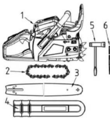
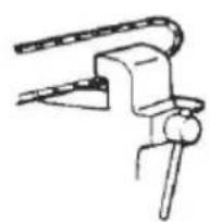
Technical diagram of a chain-linking device with numbered parts for identificationA standard saw unit package contains the items as shown below:
(1) Power unit
(2) Saw chain
(3) Guide bar
(4) Guide bar cover
(5) Plug wrench
(6) File
Open the box and install the guide bar and the saw chain on the power unit as follows.

WARNING!
The saw chain has very sharp edges. Use protective gloves for safety.
text_image
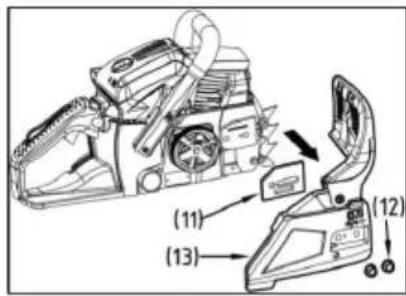
(11) (13) (12)1 Pull the guard towards the front handle to check that the chain brake is not on.
2 Loosen two nuts (12), then remove the clutch cover (13) and the spacer (11).
3 Gear the chain to the sprocket and, while fitting the saw chain around the guide bar, mount the guide bar to the power unit. Fit the chain tensioner nut (8) into the lower hole (7) of the guide bar, then install the clutch cover, and fasten the mounting nut to finger tightness. Make sure the pin (9) on the clutch cover has inserted in the hole (10) on the engine base.

text_image
(10) (7) (11) (9) (8) (12)(7) Hole
(8) Chain tensioner nut
(9) Clutch cover
(10) Hole
(11) Spacer (12)Clutch cover
(13) Nuts

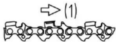
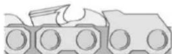
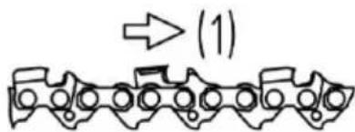
Pay attention to the correct direction of the saw chain.
(1) Moving direction
text_image
(1)
text_image
(1) (2) (3)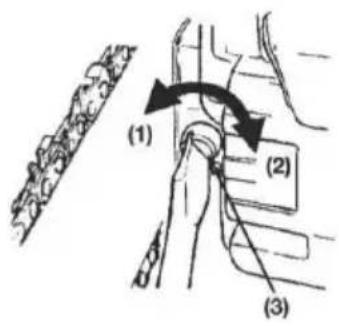
text_image
(1) (2) (3)1 Mount the guide bar then fit the saw chain around the bar and sprocket.
2 Fit the chain tensioner nut into the lower hole of the guide bar, then install the chain cover, and fasten the mounting nut to finger tightness.
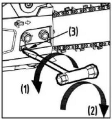
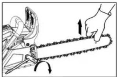
3 While holding up the tip of the bar, adjust the chain tension by turning the tensioner screw until the tie straps just touch the bottom side of the bar rail.
4 Tighten the nuts securely with the bar tip held up (12 \~ 15 Nm). Then check the chain for smooth rotation and proper tension while moving it by hand. If necessary, readjust with the chain cover loose.
5 Tighten the tensioner screw.
(1) Loosen
(2) Tighten
(3) Chain tension adjusting screw

CAUTION!
It is very important to maintain the proper chain tension. Rapid wear of the guide bar or the chain coming off easily can be caused by improper tension. Especially when using a new chain, take good care of it since it should expand when first used.
The Spiked bumper belongs to the chain saw. It must be screwed up on chain saw before the initial use. Please fix the spiked bumper with two screws on the forefront of the chain saw.
natural_image
Illustration of a hand using a chain to cut a tree branch with arrows indicating direction (no text or symbols)FUEL AND CHAIN OIL

natural_image
Illustration of a fuel being poured into a container with an oil pump icon (no text or symbols)FUEL
The engines are lubricated by oil specially formulated for air-cooled 2-cycle gasoline engine use. If oil is not available, use an antioxidant added quality oil expressly labeled for air-cooled 2-cycle engine use.
RECOMMENDED MIXING RATIO GASOLINE 40 : OIL 1
(JASO FC or ISO EGC grade formulated for air-cooled, two-stroke engines). These engines are certified to operate on unleaded gasoline.
natural_image
Illustration of a no-smoking cigarette crossed out of a campfire (no text or symbols)
WARNING!
The fuel is highly flammable. Do not smoke or bring any flame or sparks near fuel.

CAUTION!
1 FUEL WITH NO OIL(RAW GASOLINE) – It will cause severe damage to the engine inner parts very quickly 2 OIL FOR 4-CYCLE ENGINE USE or WATER COOLED 2-CYCLE ENGINE USE – It can cause spark plug fouling, exhaust port blocking, or piston ring sticking.
HOW TO MIX FUEL
1 Measure out the quantities of gasoline and oil to be mixed.
2 Put some of the gasoline into a clean, approved fuel container.
3 Pour in all of the oil and agitate well.
4 Pour in the rest of gasoline and agitate again for at least one minute.
5 Put a clear indication on the outside of the container to avoid mixing up with gasoline or other containers.
CHAIN OIL
Use special chain saw oil all year round.

text_image
chain oil
Do not use waste or regenerated oil that can cause damage to the oil pump.
OPERATION

text_image
Technical diagram of a tracked vehicle with labeled parts 1 and 2
text_image
Technical diagram showing mechanical assembly with labeled parts and directional arrows indicating motion or movement.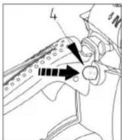
text_image
4
text_image
5
natural_image
Line drawing of a person's legs and feet wearing a high-visibility cleat (no text or symbols)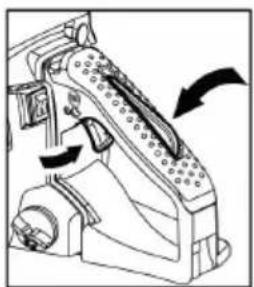
natural_image
Mechanical device diagram showing a lever mechanism with directional arrows (no text or symbols)STARTING ENGINE
1 Untwist and remove the fuel cap and oil cap. Rest the cap on a dustless place.
2 Put fuel into the fuel tank and fill the chain oil into the oil tank to 80% of the full capacity.
3 Fasten the fuel cap and oil cap securely and wipe up any fuel spillage around the unit.
4 Put the switch to the "I" position.
5 Continuously push the primer bulb until fuel comes in the bulb
(1) Oil (4) Primer bulb
(2) Fuel (5) Choke knob
(3) Engine switch
6 Pull out the choke knob. The choke will close and the throttle lever will then be set in the starting position.

When restarting immediately after stopping the engine. Set choke in the open position.

Once the choke knob has been pulled out, it will not return to the running position even if you press the throttle trigger or press down on knob with your finger. When you wish to return the choke knob to the running position, press the throttle trigger instead.
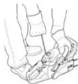
1 Push the front handle guard down toward the front to activate the chain brake.
1 While holding the saw unit securely on the ground, pull the starter rope vigorously.
1 When firing occur, press the throttle trigger to allow the choke return to the running position and pull the starter handle again to start the engine.
2 Pull up the front handle guard toward the front handle to release brake. Then, allow the engine to warm up with the trigger pulled slightly.
natural_image
Line drawing of two hands using a foot switch device (no text or symbols)
WARNING!
Before you start the engine, make sure the saw chain is not contacting anything. Make sure the chain brake always is activated before each starting.
natural_image
Illustration of a hand using a tool to lift a tree stump (no text or symbols)CHECKING OIL SUPPLY
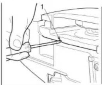
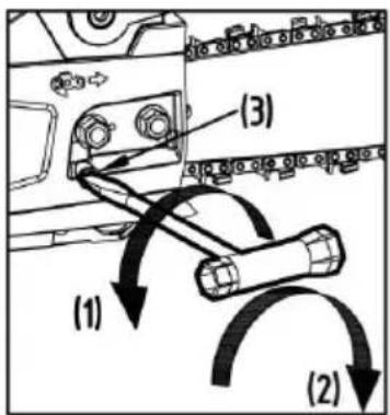
After starting the engine, run the chain at medium speed and see if chain oil is scattered off as shown in the figure.
The chain oil flow can be changed by inserting a screwdriver in the hole on bottom of the clutch side. Adjust according to your work conditions.
natural_image
Technical line drawing of a hand operating a mechanical component (no text or symbols)(1) Chain oil flow adjusting shaft
Turn the shaft counter-clockwise – Flow rich,
Turn the shaft clockwise – Flow lean.

CAUTION!
The oil tank should become nearly empty by the time fuel is used up. Be sure to refill the oil tank every time when refueling the saw.
CHECKING FUNCTIONAL OF THE CLUTCH
Before each use, you shall confirm that there is no chain movement when the chain saw running at idling speed.

WARNING!
When running, the machine must always be firmly held in both hands, with the left hand on the front hand-grip and the right hand on the rear hand grip, even if the operator is left-handed.
text_image
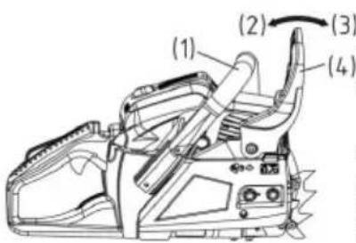
(1) (2) (3) (4)CHAIN BRAKE
The chain brake is a device which stops the chain instantaneously if the chain saw recoils due to kickback.
Normally, the brake is activated automatically by inertial force. It can also be activated manually by pushing the brake lever (Front handle guard) down toward the front. When the brake operates, a white cone pops up from the base of the brake lever. (1) Front handle (2) Release (3) Brake (4) Front handle guard
To release brake, pull up the front handle guard toward the front handle till "click" sound is heard.
text_image
Diagram showing a person using a chainsaw to cut tree bark, with Chinese labels indicating the process.
WARNING!
When the brake operates, release the throttle lever to slow down the engine speed. Continuous operation with the brake engaged will generate heat from the clutch and may cause trouble.
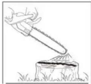
Be sure to confirm brake operation on the daily inspection.
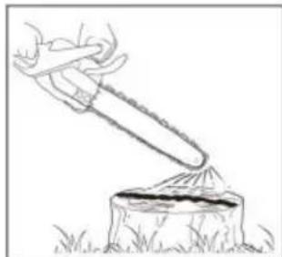
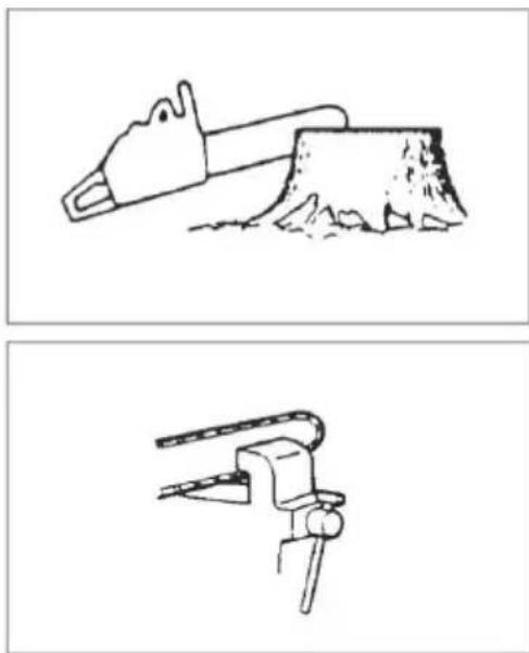
How to confirm:
1) Turn off the engine.
2) Holding the chain saw horizontally, release your hand from the front handle, hit the tip of the guide bar to a stump or a piece of wood, and confirm brake operation. Operating level varies by bar size. In case the brake is not effective, ask our dealer inspection and repairing.
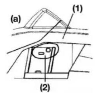
CARBURETOR ANTI-FREEZE MECHANISM
Operating chain saws in temperatures of 0 – 5°C at times of high humidity may result in ice forming within the carburetor, and this in turn may cause the output power of the engine to be reduced or for the engine to fail to operate smoothly.
(1) Cylinder cover (2) "Sunshine" mark (3) "Snow" mark (a) Normal operating mode (b) Anti-freeze mode This product has accordingly been designed with a ventilation hatch on the right side of the surface of the cylinder cover to allow warm air to be supplied to the engine and to thereby prevent icing from occurring. Under normal circumstances the product should be used in the normal operating mode, i.e., in the mode which it is set at the time of shipment.
However when the possibility exists that icing may occur, the unit should be set to operate in the anti-freeze mode before use Continuing to use the product in the anti-freeze mode even when temperatures have risen and returned to normal, may result in the engine failing to start properly or in the engine failing to operate at its normal speed, and for this reason you should always be sure to return the unit to the normal operating mode if there is no danger of icing occurring.
text_image
(a) (1) (2)
text_image
(b) (1) (3)
text_image
(1) (2) (3)HOW TO SWITCH BETWEEN OPERATING MODES
(1) Cylinder cover
(2) Choke knob
(3) Icing cap
1 Flip the engine switch to turn off the engine.
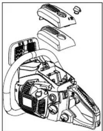
2 Remove the cover to the air filter, remove the air filter, and then remove the choke knob from the cylinder cover.
3 Loosen the screws holding the cylinder cover in place (i.e., the three screws on the inside and the one screw on the outside of the cover), and then remove the cylinder cover.
4 Press with your finger down on the icing cap located on the right-hand side of the cylinder cover to remove the icing cap.
5 Adjust the icing cap so that the "snow" mark faces upwards and then return it to its original position in the cylinder cover.
6 Fix the cylinder cover back into its original position, and then fix all other parts back into their proper positions.
text_image
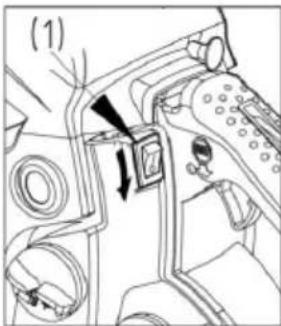
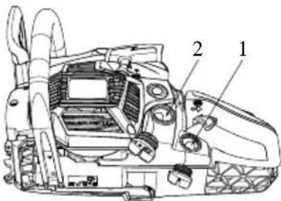
(1)STOPPING ENGINE
1 Release the throttle trigger to allow the engine idling for a few minutes.
2 Set the switch to the "O" (STOP) position.
(1) Engine switch
SAWING
natural_image
Prohibition sign showing a diagonal slash over a pipe, enclosed in a circle (no text or symbols)WARNING! Before proc
Before proceeding to your job, read "For Safe Operation" section it is recommended to first practice sawing easy logs. This also helps you get accustomed to your unit.
Always follow all the safety regulations which can restrict the use of the machine.
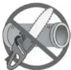
natural_image
Illustration of a hand using a tool to cut a circular object with a rotating arrow (no text or symbols)Always follow the safety regulations. The chain saw must only be used for cutting wood. It is forbidden to cut other types of material. Vibrations and kickback vary with different materials and the requirements of the safety regulations would not be respected. Do not use the chain saw as a lever for lifting, moving or splitting objects. Do not lock it over fixed stands. It is forbidden to hitch tools or applications to the P.T.O. that are not specified by the manufacturer.
natural_image
Illustration of a hand using a tool to lift a circular object, with an arrow indicating rotation (no text or symbols)It is not necessary to force the saw into the cut. Apply only light pressure while running the engine at full throttle.
It is recommended that daily inspection before use and after dropping or other impacts to identify significant damage or defects.
Racing the engine with the chain seized in a cutaway can damage the clutch system. When the saw chain is caught in the cut, do not attempt to pull it out by force, but use a wedge or a lever to open the cut.
natural_image
Illustration of a hand using a tool to cut a circular object, with an arrow indicating rotation (no text or symbols)Guard against kickback
This saw is also equipped with a chain brake that will stop the chain in the event of kickback if operating properly. You must check the chain brake operation before each usage by running the saw at full throttle for 1 or 2 seconds and pushing the front hand guard forward. The chain should stop immediately with the engine at full speed. If the chain is slow to stop or does no stop then replace the brake band and clutch drum before use.
It is extremely important that the chain brake be checked for proper operation before each use and that the chain be sharp in order to maintain the kickback safety level of this saw. Removal of the safety devices, inadequate maintenance, or incorrect replacement of the bar or chain may increase the risk of serious personal injury due to kickback.
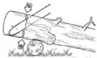
Felling a tree
natural_image
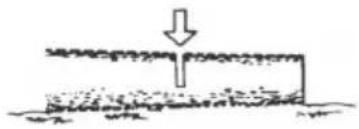
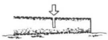
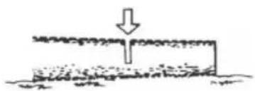
Simple line drawing of a ground surface with a downward arrow indicating a drop or fall (no text or symbols)1 Decide the felling direction considering the wind, lean of the tree, location of heavy branches, ease of job after felling, and other factors.
2 While clearing the area around the tree, arrange a good foothold and retreat path.
3 Make a notch cut one-third of the way into the tree on the felling side.
4 Make a felling cut from the opposite side of the notch and at a level slightly higher than the bottom of the notch.

WARNING!
When you fell a tree, be sure to warn your neighboring workers of the danger.
(A) Notch cut
(B) Felling cut
Logging and limbing

WARNING!
1 Always ensure your foothold as well as stability of the tree.
2 Be alert to the rolling over of a cut log.
3 Read the instructions in "For Safe Operation" to avoid kick-back of the saw. Before starting work, check the direction of bending force inside the log to be cut. Always finish cutting from the opposite side of bending direction to prevent the guide bar from being caught in the cutaway.
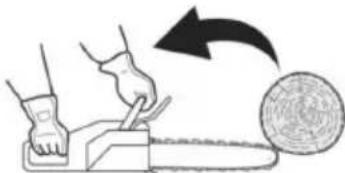
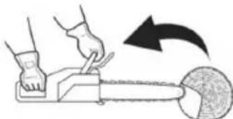
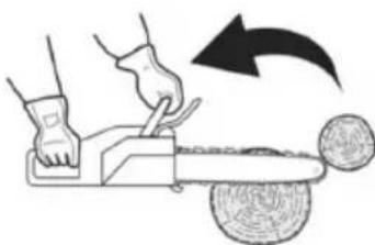
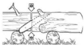
■ Cutting an unpillowed log
Saw down halfway, then roll the log over and cut from the opposite side.
text_image
Diagram illustrating a logging or tree clearing scene with labeled arrows and a circular object, likely illustrating a logging or forest clearing problem.
text_image
Diagram illustrating a physics experiment with a moving cart and rotating wheels, showing force direction and angle of motion.Cutting a pillowed log
In the area A in the picture right above, saw up from the bottom one-third and finish by sawing down from the top. In the area B, saw down from the top one-third and finish by sawing up from the bottom.

text_image
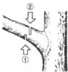
Diagram illustrating airflow or heat transfer between two circular objects with numbered arrows indicating direction of movement.Limbing a felled tree
First check which way the limb is bent. Then make a shallow cut into the compressed side to prevent the limb from being torn. Cut through from the tensed side.

WARNING!
Be alert to the spring back of a cut limb.
text_image
Diagram showing two labeled arrows pointing to a curved structure with annotations ① and ②
natural_image
Two hand-drawn diagrams showing a person climbing a ladder and standing on a crossbar, with no text or symbols present.Pruning
Cut up from the bottom, finish down from the top.

WARNING!
1 Do not use an unstable foothold or a stepladder.
2 Do not overreach.
3 Do not cut above shoulder height.
4 Always use both hands to grip the saw.

WARNING!
The Spiked bumper must always be put on while using the chain saw on tree trunk. Push the spiked bumper into the tree trunk by using the rear handle. Push the front handle in the direction of cutting line. The spiked bumper must be remaining set for further saw guiding if necessary. Use a spiked bumper when cutting trees and thick branches can ensure your safety and decrease the working strength and vibration level.
If there's barrier between the cutting material and chainsaw, turn off the machine. Wait until it stops completely. Wear the safety glove and remove the barrier. If the chain must be removed, please follow the instruction of relevant part like installation in manual. A trial run must be conducted after the cleaning and newly installation. If vibration or mechanical noise is discovered, please stop the use and contact your dealer.
MAINTENANCE
natural_image
Exploded view diagram of a mechanical device showing internal components and housing (no text or labels)
natural_image
Hand holding a small object with a spiral arrow, no text or symbols visible
WARNING!
Before cleaning, inspecting or repairing your unit, make sure that engine has stopped and is cool. Disconnect the spark plug to prevent accidental starting.
Follow the instructions to carry out regular maintenance, pre-operating procedures and daily maintenance routines. Improper maintenance may result in serious damage to the machine.
Maintenance after each use
1. Air filter
Dust on the cleaner surface can be removed by tapping a corner of the cleaner against a hard surface. To clean dirt in the meshes, split the cleaner into halves and brush. When using compressed air, blow from the inside. To assemble the cleaner halves, press the rim until it clicks.
natural_image
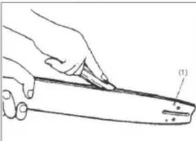
Technical line drawing of a mechanical device with labeled parts (1), showing internal components and no readable text or symbols.2. Oiling port
Dismount the guide bar and check the oiling port for clogging.
(1) Oiling port
natural_image
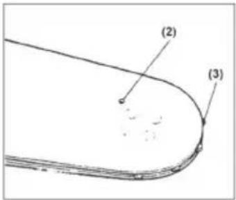
Illustration of a hand holding a tool with a labeled part (1), no text or symbols present3. Guide bar
When the guide bar is dismounted, remove sawdust in the bar groove and the oiling port.
Grease the nose sprocket from the feeding port on the tip of the bar.
(1) Oiling port
(2) Grease port
(3) Sprocket
4. Others
Check for fuel leakage and loose fastenings and damage to major parts, especially handle joints and guide bar mounting. If any defects are found, make sure to have them repaired before operating again.
text_image
(2) (3)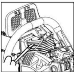
natural_image
Technical diagram of a vehicle's internal components, possibly engine or motor assembly (no visible text or labels)Periodical service points
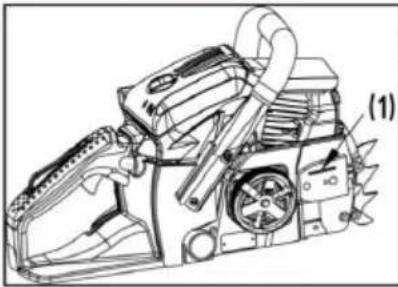
1. Cylinder fins
Dust clogging between the cylinder fins will cause overheating of the engine. Periodically check and clean the cylinder fins after removing the air cleaner and the cylinder cover. When installing the cylinder cover, make sure that switch wires and grommets are positioned correctly in place.
natural_image
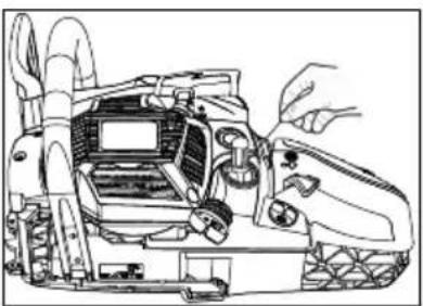
Technical line drawing of a mechanical device with no visible text or symbols2. Fuel filter
(a) Using a wire hook, take out the filter from the filler port.
(1) Fuel filter
(b) Disassemble the filter and wash, or replace with a new one if needed.

WARNING!
■ After removing the filter, use a pinch to hold the end of the suction pipe.
When assembling the filter, take care not to allow filter fibers or dust inside the suction pipe.
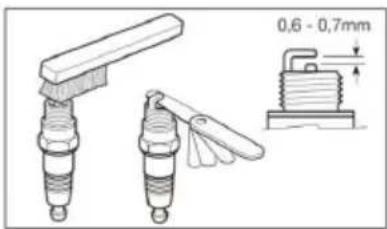
3. Spark plug
Clean the electrodes with a wire brush and reset the gap to 0.65mm as necessary.
Spark plug type: NHSP LD L8RTF or CHAMPION RCJ7Y or NGK BPMR7A
text_image
0,6 - 0,7mm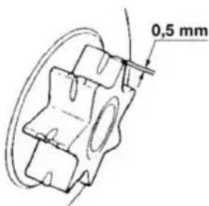
text_image
0,5 mm4. Sprocket
Check for cracks and for excessive wear interfering with the chain drive. If the wear is considerable, replace it with new one. Never fit a new chain on a worn sprocket, or a worn chain on a new sprocket.
5. Front and Rear dampers
Replace if adhered part is peeled or crack is observed on the rubber part. Replace if the inside of the rear damper metal has been beaten by the stopper bolt and the clearance of the metal increased.

WARNING!
Use only the spare parts which named in this manual. Use the other spare part can cause serious injury.
MAINTENANCE OF SAW CHAIN AND GUIDE BAR
natural_image
Two line drawings of a saw cutting into a tree stump, shown from different angles (no text or symbols)Saw chain

WARNING!
It is very important for smooth and safe operation to keep the cutters always sharp.
Your cutters need to be sharpened when:
Sawdust becomes powder-like
You need extra force to saw in
The cut way does not go straight
Vibration increases
Fuel consumption increases.
Cutter setting standards:

WARNING!
Be sure to wear safety gloves.
Before filing:
■ Make sure the saw chain is held securely.
■ Make sure the engine is stopped.
Use a round file of proper size for your chain.
Chain type:
6238: Oregon 91P
6240: Oregon 91P
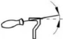
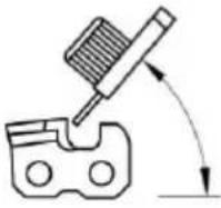
File size: 5/32"(4.0mm) for 91P Place your file on the cutter and push straight forward. Keep the file position as illustrated.
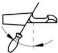
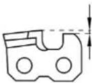
After every cutter has been set, check the depth gauge and file it to the proper level as illustrated.

WARNING!
Be sure to round off the front edge to reduce the chance of kickback or tie-strap breakage.
Make sure every cutter has the same length and edge angles as illustrated.
| Type of chain | File diameter Top plate angle Down angle | Head tilt angle (55°) | Depth gauge standard | ||
 |  |  |  |  | |
| Vise ro-tate angle | Vise tilt angle Side angle | ||||
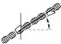 | 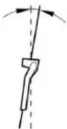 | 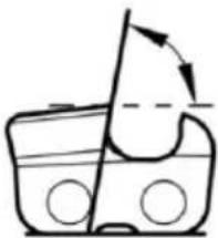 | |||
| 91P 5/32" | 30° 0° 80° 0.025" | ||||
| 95VPX 3/16" | 30° 10° 80° 0.025" | ||||
 |  | ||||
| Depth gauge File | |||||
text_image
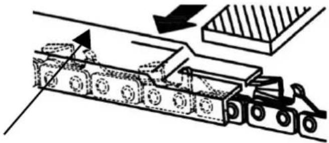
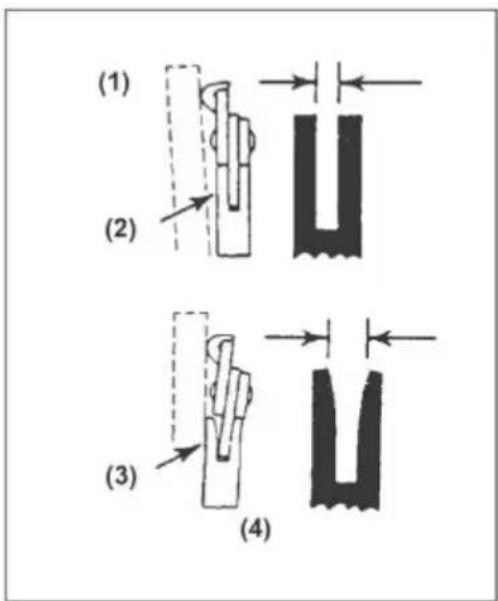
(1) (2) (3) (4)Guide bar
■ Reverse the bar occasionally to prevent partial wear.
The bar rail should always be a square. Check for wear of the bar rail. Apply a ruler to the bar and the outside of a cutter. If a gap is observed between them, the rail is normal. Otherwise, the bar rail is worn. Such a bar needs to be corrected or replaced.
(1) Ruler (2) Gap (3) No gap
(4) Chain
tilts

WARNING!
The table contains a list of all possible combinations between bar and chain, indicating those which may be used on each machine, marked with the symbol “*”.
| Pitch Guide bar Chain Chain saw model | ||||||
| Zoll LengthInches/cm | Groove widthInches/mm | Code Code | 6238 6240 | |||
| 3/8” 14”/35 cm 0.050”/1.3 mm Oregon | 140SDEA041 | Oregon91P053X | * | |||
| 3/8” 16”/40 cm 0.050”/1.3 mm Oregon | 160SDEA041 | Oregon91P057X | * | |||
For replacement use only above bars and chains. If you use non-approved combinations it may cause serious personal injury and damage to the machine.
STORAGE
1 Empty the fuel tank and run the engine out of fuel.
2 Empty the oil tank.
3 Clean the entire unit.
4 Store the unit in a dry place out of the reach of children.
WASTE DISPOSAL AND ENVIRONMENTAL PROTECTION
Never pour remainders of chain lubricant or 2-stroke fuel mixture in the drain or sewerage system or soil, but dispose of it in a proper, environmentally friendly way, e.g., at a special collecting point or dump.
If your device should become useless somewhere in the future or you do not need it any longer, do not dispose of the device together with your domestic refuse, but dispose of it in an environmentally friendly manner. Thoroughly empty the oil/lubricant and fuel tanks and dispose of the remainders at a special collecting point or dump. Please also dispose of the device itself at an according collecting/recycling point. By doing so, plastic and metal parts can be separated and recycled. Information concerning the disposal of materials and devices are available from your local administration.
TROUBLESHOOTING GUIDE
| PROBLEM | CAUSE | REMEDY |
1) Starting failure WARNING!Make sure the icing prevention system is not working. WARNING!Make sure the icing prevention system is not working. | Check fuel for water or sub-standard mixture | Replace with proper fuel |
| Check for engine flooding | Remove and dry the spark plugthen pull the starter again with no choke | |
| Check spark ignition | Replace with a new plug | |
| 2) Lack of power / Poor ac-celeration / Rough idling | Check fuel for water or sub-standard mixture | Replace with proper fuel |
| Check air filter and fuel filter for clogging | Clean | |
| PROBLEM CAUSE REMEDY | ||
| Check carburetor for inadequate adjustment | Readjust speed needles | |
| Check oil for substandard quality | Replace3) Oil does not come out | |
| Check oil passage and ports for clogging | Clean |
If the unit seems to need further service, please consult with an authorized service shop in your area.
SPECIFICATIONS
| Type 6238 6240 | ||
| Art-no. 127387 127392 | ||
| Displacement 37.2 cm | ^3 | 40.1 cm^3 |
| Max engine power 1.2 kW 1.5 kW | ||
| Length guide bar (OREGON) | 35 cm140SDEA041 | 40 cm160SDEA041 |
| Useable cutting length 33 cm 37 cm | ||
| Saw chain (OREGON) 91P053X 91P057X | ||
| Thickness of drive links gauge 1.27 mm | 1.27 mm | |
| Pitch - chain sprocket 3/8" | 3/8" | |
| Drive train tooth count | 6z/6T | 6z/6T |
| Chain brake | yes | yes |
| Idling rotational speed | 3100 ± 300 r/min | 3100 ± 300 r/min |
| Max. rotational speed (with cutting at- tachment) | 11000 r/min | 11000 r/min |
| Max. chain speed | 21 m/s | 21 m/s |
| Fuel tank capacity | 390 ml | 390 ml |
| Chain oil tank capacity 210 ml | 210 ml | |
| Fuel mixture ratio | 40:1 | 40:1 |
| Net weight without chain and guide bar, empty tanks | 4.6 kg 4.6 kg | |
| Fuel consumption at maximum engine power | 450 g/kWh | 450 g/kWh |
| Sound power level LWA(EN ISO 11681)(K=3) | 108.4 dB(A) 110.1 dB(A) | |
| Sound pressure value LPA(EN ISO 11681) (K=3) | 97.6 dB(A) | 99.5 dB(A) |
| Max. vibration acceleration avhw(K=1.5) | ||
| Front handle | 6.2 m/s^2 | 8.5 m/s^2 |
| Rear handle | 11.3 m/s^2 | 9.0 m/s^2 |
| Guaranteed sound power level LWA(2000/14/EG+2005/88/EC) | 112 dB(A) | 113 dB(A) |
WARRANTY
We will address claims for any defects in materials and workmanship during the statutory period of limitation by means of repairs or replacements of our choice. The period of limitation is governed by the laws of the country in which the machine was purchased.
Our warranty applies only if:
The machine has been properly handled
The operating instructions have been adhered to
■ Original replacement parts have been used
The warranty is no longer in effect if:
■ Efforts have been made to repair the machine
■ Technical modifications have been made to the machine
The machine has not been used for its intended purpose
The warranty does not cover:
■ Damage to paint work through normal use
Parts subject to wear as indicated in the replacement parts list with a box [xxx xxx (x)]
Internal combustion engines – separate warranty conditions of the respective engine manufacturer apply
The warranty period begins with the purchase by the first buyer. The warranty period begins on the date that appears on the original purchase receipt. In the event of a warranty claim, please your contact supplier or the nearest authorised customer service centre with this warranty declaration and the purchase receipt in hand. This warranty does not affect the legal warranty claims by the purchaser against the seller.
EC DECLARATION OF CONFORMITY
We hereby declare that this product, in the form in which it is marketed, meets the requirements of the harmonised EU guidelines, EU safety standards, and the product-specific standards.
Produkt Manufacturer Executive Officer
Model EU directives Harmonised standards
| 6238 2006/42/EG | EN ISO 11681-1:2011 | |
| 6240 | 2000/14/EG | EN ISO 14982:2009 |
| 2014/30/EU | EN ISO 22868:2011 |
Sound power level
measured / guaranteed
6238 - 108/112 dB(A)
6240 - 110/113 dB(A)
Conformity evaluation
2000/14/EG Appendix V
Building sample examination to Notified body Kötz, 08.07.2016
GSPG §4 BM 1027 MSR
text_image
Technical diagram of a chain-linking device with numbered parts for identificationtext_image
(11) (13)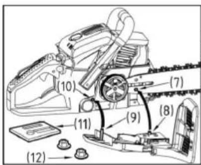
text_image
(10) (7) (11) (9) (8) (12)natural_image
Illustration of a hand using a chain-linking tool to lift a tree branch (no text or symbols)natural_image
Illustration of a fuel being poured into a gas cylinder with an oil pump icon (no text or symbols)BRANDSTOF
natural_image
Illustration of a no-smoking cigarette crossed out of a campfire (no text or symbols)
WAARSCHUWING!
text_image
chain oil
text_image
Technical diagram of a tracked vehicle with labeled parts 1 and 2
natural_image
Technical diagram of a mechanical assembly with no visible text or symbols
text_image
4
text_image
5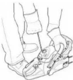
natural_image
Line drawing of a person's legs and feet wearing athletic shoes (no text or symbols)
natural_image
Technical line drawing of a mechanical device with directional arrows indicating motion (no text or symbols)DE MOTOR INSCHAKELEN
natural_image
Line drawing of a person using a mechanical device (no text or symbols)
WAARSCHUWING!
natural_image
Line drawing of a hand using a long-handled tool to lift a tree stump (no text or symbols)OLIETOEVOER CONTROLEREN
natural_image
Illustration of a person using a chainsaw to cut tree bark (no text or symbols)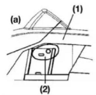
text_image
(a) (1) (2)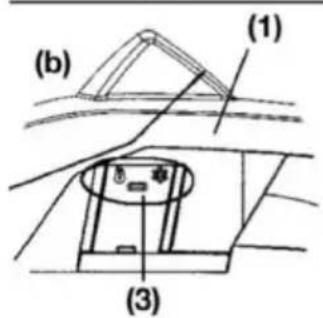
text_image
(b) (1) (3)
text_image
(1) (2) (3)
WAARSCHUWING!
CARBURATEUR-VRIESBESCHERMING
natural_image
Prohibition sign showing a diagonal slash over a pipe, crossed out by a diagonal line (no text or symbols)natural_image
Illustration of a person using a power tool to cut a circular object with a black arrow indicating rotation (no text or symbols)natural_image
Illustration of a person using a power tool to cut a circular object with a curved arrow indicating rotation (no text or symbols)natural_image
Illustration of a hand using a cutting tool to cut a circular object, with an arrow indicating rotation (no text or symbols)natural_image
Pure mechanical component diagram without any text, numbers, or symbolsnatural_image
Simple line drawing of a ground surface with a downward arrow indicating a point of interest (no text or symbols)Omzagen en snoeien

WAARSCHUWING!
text_image
Diagram illustrating a logging or logging process with labeled arrows and directional arrows, including a circular object on grass.text_image
Diagram illustrating a logging or drilling process with labeled components and directional arrows, including symbols like '0' and '61'.text_image
Diagram illustrating airflow around a circular object with labeled parts ① and ②, showing directional arrows.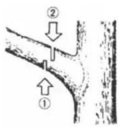
text_image
Diagram showing two labeled arrows pointing to a pipe or channel with annotations ① and ②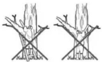
natural_image
Two hand-drawn diagrams showing tree branches with leaves and a ladder, no text or symbols presentnatural_image
Exploded view diagram of a mechanical device showing internal components and housing (no text or labels)
WAARSCHUWING!
natural_image
Hand holding a small object with a spiral arrow, no visible text or symbolsnatural_image
Technical line drawing of a mechanical device with gears and levers (no text or symbols)2. Olieaansluiting
natural_image
Illustration of a hand holding a tool with a ruler, showing the process (no text or symbols present)natural_image
Technical line drawing of a car engine bay with internal components (no text or symbols)natural_image
Technical line drawing of a mechanical device with hands operating it (no text or symbols present)2. Brandstofffilter
natural_image
Simple line drawing of a hand holding a tool above a rock, no text or symbols present
natural_image
Simple line drawing of a mechanical clamp or bracket assembly (no text or symbols)Zaagketting

WAARSCHUWING!
DÉCLARATION DE CONFORMITÉ CE....95

ATTENTION!
text_image
Illustration showing four different types of playground equipment: slide, toilet, no litter, and fire extinguisher.text_image
Technical diagram of a chain-linking device with numbered parts for identificationtext_image
(11) (13)
text_image
(10) (7) (11) (9) (8) (12)natural_image
Illustration of a hand using a chain-linking tool to lift a tree branch (no text or symbols)natural_image
Illustration of a fuel being poured into a gas cylinder with an oil pump icon (no text or symbols)CARBURANT
natural_image
Illustration of a no-smoking cigarette crossed out of a campfire (no text or symbols)
AVERTISSEMENT!
text_image
chain oil
text_image
Technical diagram of a tracked vehicle with labeled parts 1 and 2
text_image
3
text_image
4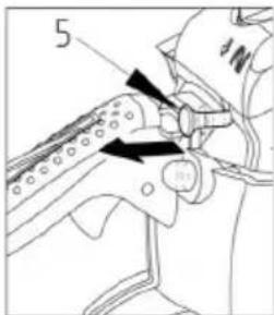
text_image
5
natural_image
Line drawing of a person's legs and feet wearing a high-visibility athletic shoe (no text or symbols)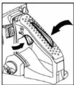
natural_image
Technical line drawing of a mechanical device with directional arrows indicating motion (no text or symbols)MISE EN MARCHE DU MOTEUR
natural_image
Line drawing of a person's legs and feet wearing a high-visibility athletic shoe (no text or symbols)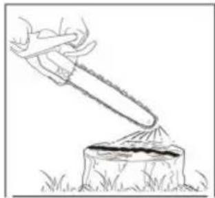
natural_image
Illustration of a hand using a tool to lift a rock, with grass at the base (no text or symbols)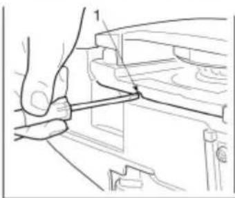
natural_image
Technical line drawing of a hand operating a tool on a mechanical component (no text or symbols)
AVERTISSEMENT!
text_image
Diagram illustrating a manual logging process with a chainsaw and tree stump, showing gear movement and cutting steps.
AVERTISSEMENT!
text_image
(a) (1) (2)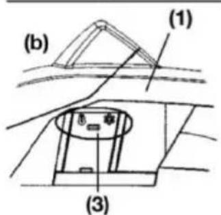
text_image
(b) (1) (3)
text_image
(2) (1) (3)COMMUTATION DU MODE DE SERVICE
natural_image
Prohibition sign showing a diagonal slash over a pipe, enclosed in a circle (no text or symbols)natural_image
Illustration of a person using a power tool to cut a circular object with a curved arrow indicating rotation (no text or symbols)natural_image
Illustration of a person using a tool to cut a circular object with a curved arrow indicating rotation (no text or symbols)natural_image
Illustration of a hand using a cutting tool to cut a ball, with an arrow indicating motion (no text or symbols)natural_image
Simple line drawing of a ground surface with a downward arrow indicating a drop or fall (no text or symbols)Sciage et élagage

AVERTISSEMENT!
natural_image
Simple line drawing of a log being cut with arrows indicating direction, no text or symbols presenttext_image
Diagram illustrating a mechanical or hydraulic system with labeled components and directional arrows, likely depicting a physical or hydraulic system.text_image
Diagram illustrating airflow around a tree trunk with labeled parts ① and ②, showing streamlines and directional arrows.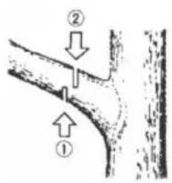
text_image
Diagram showing two labeled arrows pointing to a pipe or channel with directional indicators (① and ②) indicating flow or movement.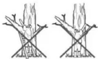
natural_image
Two identical line drawings of a tree with branches and leaves, no text or symbols present.natural_image
Technical line drawing of a mechanical device with exploded view (no text or symbols)
AVERTISSEMENT!
natural_image
Hand holding a small object with a spiral arrow, no visible text or symbolsnatural_image
Technical line drawing of a mechanical device with gears and components (no text or symbols)2. Raccord d'huile
natural_image
Line drawing of a hand holding a tool, with no visible text or symbolsnatural_image
Interior view of a car showing engine, air intake manifold, and exhaust system (no text or symbols visible)natural_image
Technical line drawing of a tracked vehicle with visible components and no text or symbolsnatural_image
Simple line drawing of a saw cutting through a tree stump (no text or symbols)Type de chaîne

AVERTISSEMENT!
DÉCLARATION DE CONFORMITÉ CE
text_image
Technical diagram of a chain-linking device with numbered parts for identificationnatural_image
Illustration of a hand using a chain-linking tool to interact with a gear (no text or symbols present)natural_image
Illustration of a fuel being poured into a container with an oil drop and plus sign (no text or symbols)CARBURANTE
natural_image
Illustration of a no-smoking cigarette crossed out of a campfire (no text or symbols)
AVVISO!
text_image
chain oil
text_image
Technical diagram of a tracked vehicle with labeled parts 1 and 2
text_image
3
text_image
4
text_image
5
natural_image
Line drawing of a person's legs and feet wearing a high-visibility athletic shoe (no text or symbols)
natural_image
Mechanical device diagram showing a lever mechanism with directional arrows (no text or symbols)AVVIAMENTO MOTORE
natural_image
Line drawing of a person's legs and feet wearing athletic shoes (no text or symbols)
AVVISO!
natural_image
Illustration of a hand using a tool to lift a tree stump (no text or symbols)natural_image
Line drawing of a hand using a tool to adjust or install a mechanical component (no text or symbols present)text_image
Diagram illustrating a manual logging process with a chainsaw and tree stump, showing gear movement and cutting steps.
AVVISO!
text_image
(a) (1) (2)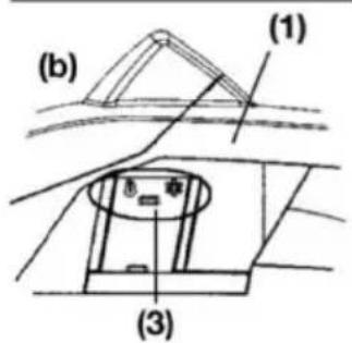
text_image
(b) (1) (3)
text_image
(1) (2) (3)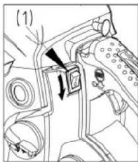
text_image
(1)COME PASSARE DA UNA MODALITÀ OPERATIVA A UN'ALTRA
natural_image
Prohibition sign showing a diagonal slash over a cylindrical pipe, enclosed in a circle (no text or symbols)
AVVISO!
natural_image
Illustration of a person using a power tool to cut a circular object with a net, showing motion direction (no text or symbols)natural_image
Illustration of a person using a power tool to cut a circular object with a black arrow indicating rotation (no text or symbols)natural_image
Illustration of a hand using a tool to cut a ball on a cutting board, with an arrow indicating motion (no text or symbols)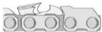
natural_image
Simple line drawing of a ground surface with a downward arrow indicating a drop or fall (no text or symbols)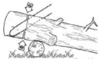
text_image
Diagram illustrating a logging or tree clearing scene with arrows indicating direction and a scale marker, showing a log rolling down grass.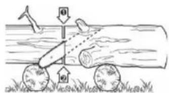
text_image
Diagram illustrating a mechanical or physical setup with labeled components and directional arrows, possibly depicting a moving cart or tool path.
text_image
Diagram illustrating airflow around a cylindrical object with labeled parts ① and ②, showing directional arrows.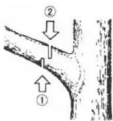
text_image
Diagram showing two labeled arrows pointing to a curved pipe or channel, with numbers ① and ② indicating directional flow.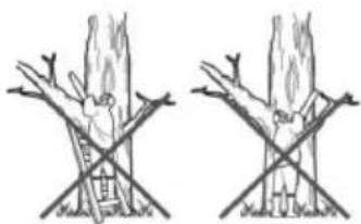
natural_image
Two hand-drawn diagrams showing tree branches with a ladder and crosshairs, no text or symbols present.natural_image
Exploded view diagram of a mechanical device showing internal components and housing (no text or labels)
AVVISO!
natural_image
Hand holding a small object with a spiral arrow, no visible text or symbolsnatural_image
Technical line drawing of a mechanical device with gears and levers (no text or symbols)natural_image
Illustration of a hand holding a tool with a labeled part (1), no text or symbols present3. Barra
natural_image
Technical line drawing of a vehicle engine bay with internal components (no text or symbols)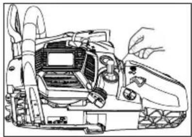
natural_image
Technical line drawing of a tracked vehicle with visible components and no text or symbolsnatural_image
Simple line drawing of a hand using a saw to cut a tree stump (no text or symbols)
natural_image
Simple line drawing of a mechanical clamp or bracket assembly (no text or symbols)Catena

AVVISO!
text_image
Technical diagram of a chain-linking device with numbered parts for identificationnatural_image
Illustration of a hand using a chain to cut a tree branch with arrows indicating direction (no text or symbols)GORIVO IN VERIŽNO OLJE

natural_image
Illustration of a fuel being poured into a container with an oil pump icon (no text or symbols)GORIVO
natural_image
Illustration of a no-smoking cigarette crossed out of a campfire (no text or symbols)
OPOZORILO!
text_image
chain oil
text_image
Technical diagram of a tracked vehicle with labeled parts 1 and 2
text_image
Technical diagram showing mechanical assembly with labeled parts and directional arrows indicating motion or movement.
text_image
4
text_image
5
natural_image
Line drawing of a person's legs and feet wearing a high-visibility cleat (no text or symbols)
natural_image
Technical line drawing of a mechanical device with directional arrows indicating motion (no text or symbols)ZAGON MOTORJA
1 Odvijte in odstranite pokrovčka za dolivanje goriva in olja. Pokrov odložite na mesto, kjer ni prahu.
natural_image
Line drawing of two hands using a foot switch device (no text or symbols)
OPOZORILO!
natural_image
Illustration of a hand using a tool to lift a tree stump (no text or symbols)PREVERITE DOVOD OLJA
natural_image
Technical line drawing of a hand operating a mechanical component (no text or symbols)text_image
Diagram showing a person using a chainsaw to cut tree bark, with Chinese labels indicating the process.
OPOZORILO!
text_image
(a) (1) (2)
text_image
(b) (1) (3)
text_image
(1) (2) (3)PREKLOP NAČINA OBRATOVANJA
(1) Pokrov cilindra
(2) Gumb lopute za zrak
(3) Kapica proti zaledenitvi
1 Motor ustavite s stikalom za motor.
2 Odstranite pokrov filtra za zrak in filter za zrak, nato snemite gumb lopute za zrak s pokrova cilindra.
3 Odvijte pritrdilne vijake s pokrova cilindra (torej tri vijake na notranji strani in en vijak na zunanji strani pokrova) in snemite pokrov cilindra.
4 Kapico proti zaledenitvi na desni strani pokrova cilindra pritisnite s prsti navzdol in snemite kapico.
5 Kapico proti zaledenitvi nastavite tako, da je simbol snežinke obrnjen navzgor in kapico znova vstavite v pokrov cilindra.
6 Znova namestite pokrov cilindra in vse druge dele v ustrezen položaj.
text_image
(1)UGAŠANJE MOTORJA
natural_image
Prohibition sign showing a diagonal slash over a pipe, enclosed in a circle (no text or symbols)natural_image
Illustration of a hand using a saw to cut a circular object with a rotating arrow (no text or symbols)natural_image
Illustration of a hand using a tool to lift a circular object, with an arrow indicating rotation (no text or symbols)natural_image
Illustration of a hand using a tool to cut a circular object, with an arrow indicating rotation (no text or symbols)Zaščita pred povratnim udarcem

natural_image
Simple line drawing of a ground surface with a downward arrow indicating a point of interest (no text or symbols)text_image
Diagram illustrating a logging or logging process with labeled arrows and numbered componentsŽaganje neuležajenega debla
Deblo razžagajte do polovice, nato ga prekotalite in dokončajte rez na drugi strani.
text_image
Diagram illustrating a mechanical or hydraulic system with labeled components and directional arrows, likely depicting a physical or agricultural process.Žaganje uležajenega debla
text_image
Diagram illustrating airflow or heat transfer between two circular objects with labeled arrows and directional arrowstext_image
Diagram showing two labeled arrows pointing to a curved structure with annotations ① and ②
natural_image
Two identical line drawings of a tree with branches and leaves, no text or symbols present.Prirezovanje
natural_image
Exploded view diagram of a mechanical device showing internal components and housing (no text or labels)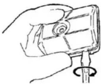
natural_image
Hand holding a small electronic device with a scroll wheel, no visible text or symbols
OPOZORILO!
natural_image
Technical line drawing of a mechanical device with labeled parts (1), showing internal components and no readable text or symbols.natural_image
Line drawing of a hand holding a tool with a labeled component (1), no text or symbols present3. Vodilo (meč)
natural_image
Technical diagram of a vehicle engine bay with no visible text or symbolsnatural_image
Technical line drawing of a mechanical device with no visible text or symbols2. Filter za gorivo
(a) S kavljem iz žice izvlecite filter iz polnilnega nastavka.
(1) Filter za gorivo
(b) Razstavite filter in ga sperite oz. zamenjajte.

OPOZORILO!
Po demontaži filtra s kleščami trdno primite konec sesalne cevi.
Pri vgradnji filtra pazite, da v sesalno cev ne pridejo vlakna filtra ali prah.
3. Vžigalna svečka
natural_image
Simple line drawing of a saw cutting into a tree stump (no text or symbols)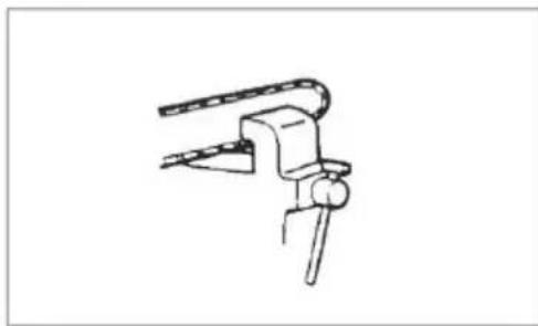
natural_image
Simple line drawing of a mechanical clamp or bracket assembly (no text or symbols)Veriga žage

OPOZORILO!
2000/14/EC Dodatek V
Tipski preskus v skladu s GSPG Priglašeni organ Kötz, 03.05.2016
§4 BM 1027 MSR
text_image
Technical diagram of a chain-linking device with numbered parts for identificationtext_image
(11) (13)1 Povucite štitnik prema prednjem rukohvatu kako biste se uvjerili da kočnica lanca nije uključena.
2 Otpustite dvije matice (12), zatim uklonite pokrov spojke (13) i distantni element (11).
3 Lanac stavite na lančanik, lanac postavite oko vodilice i vodilicu montirajte na pogonsku jedinicu. Maticu za zatezanje lanca (8) umetnite u donji provrt (7) vodilice, montirajte pokrov spojke i rukom čvrsto zategnite sigurnosnu maticu. Pazite da zatik (9) pokrova spojke zahvati u provrt (10) na donjem dijelu motora.

text_image
(10) (7) (11) (9) (8) (12)(7) Provrt (8) Matica za zatezanje lanca
(9) Poklopac spojke (10) Provrt
(11) Distantni element (12)Poklopac spojke
(13) Matice

Pazite na ispravan smjer kretanja lanca.
(1) Smjer kretanja
text_image
(1)
text_image
(1) (2) (3)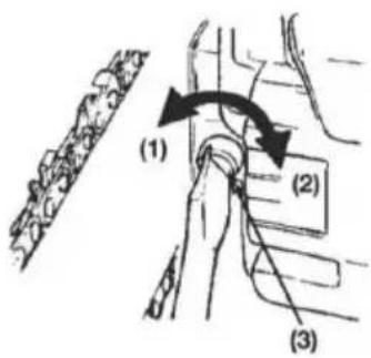
text_image
(1) (2) (3)1 Montirajte vodilicu i lanac stavite na vodilicu i lančanik.
2 Maticu za zatezanje lanca umetnite u donji provrt vodilice, montirajte pokrov lanca i rukom čvrsto zategnite sigurnosnu maticu.
3 Vodilicu držite vrhom prema gore i zategnutost lanca podesite okretanjem vijka za zatezanje sve dok stezne trake upravo dodirnu donji dio vodilice.
4 Vodilicu držite vrhom prema gore i zategnite matice (12-15 Nm). Za-tim lanac pomaknite rukom i provjerite može li se pomicati bez trzanja te je li ispravno zategnut. Po potrebi podesite lanac dok je pokrov otpušten.
5 Zategnite stezni vijak.
(1) Otpuštanje
(2) Zatezanje
(3) Vijak za stezanje lanca

POZOR!
Ispravna zategnutost lanca je vrlo važna. Pogrešna zategnutost može dovesti do prerane istrošenosti vodilice ili do čestog iskakanja lanca. Osobito s novim lancem treba postupati oprezno budući da se prilikom prve upotrebe još može izdužiti.
Kandže za stablo su dio lančane pile. Prije prve upotrebe ih treba zavrnuti na lančanu pilu. Kandže moraju uvijek na prednjoj strani biti učvršćene pomoću dva vijka.

natural_image
Illustration of a hand using a chain-linking tool to lift a tree branch (no text or symbols)GORIVO I ULJE ZA LANAC

natural_image
Illustration of a fuel being poured into a gas cylinder with an oil pump icon (no text or symbols)GORIVO
natural_image
Illustration of a no-smoking cigarette crossed out of a campfire (no text or symbols)
UPOZORENJE!
Gorivo je lako zapaljivo. U blizini goriva ne pušite i izbjegavajte plamen i iskrenje.

POZOR!
text_image
chain oil
Ne koristite staro ulje ili obrađeno ulje koje može oštetiti uljnu pumpu.
RUKOVANJE
text_image
Technical diagram of a tracked vehicle with labeled parts 1 and 2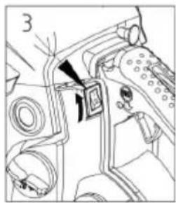
natural_image
Technical diagram of a mechanical assembly with no visible text or symbols
text_image
4
text_image
5
natural_image
Line drawing of a person's legs and feet wearing a high-visibility cleat (no text or symbols)
natural_image
Technical line drawing of a mechanical device with directional arrows indicating motion (no text or symbols)UKLJUČIVANJE MOTORA
1 Oslobodite i uklonite poklopac spremnika goriva i ulja. Poklopac odložite na mjesto na kojem nema prašine.
2 U uređaj ulijte gorivo i spremnik ulja napunite uljem za lanac do razine od 80%.
3 Poklopac spremnika za gorivo i ulje opet zavrnite i event. obrišite proliveno gorivo.
4 Prekidač okrenite na "I".
natural_image
Line drawing of a person using a foot switch device (no text or symbols)
UPOZORENJE!
Prije pokretanja motora provjerite da li pila dodiruje predmete ili ljude. Prije svakog pokretanja pazite je li kočnica lanca aktivirana.
natural_image
Line drawing of a hand using a tool to lift a tree stump (no text or symbols)PROVJERA OPSKRBE ULJEM
Nakon pokretanja motora lanac pustite da radi srednjom brzinom i provjerite brizga li se ulje kao na slici.
natural_image
Technical line drawing of a mechanical component with a hand operating a tool (no text or symbols present)(1) Vratilo za podešavanje protoka ulja
natural_image
Illustration of a person using a chainsaw to cut tree bark (no text or symbols)
text_image
(a) (1) (2)
text_image
(b) (1) (3)
text_image
(1) (2) (3)
UPOZORENJE!
natural_image
Symbol of a crossed saw cutting through pipes, enclosed in a circle (no text or labels)
UPOZORENJE!
Prije početka rada pročitajte poglavlje "Sigurnosne upute za rad"; pilu treba najprije provjeriti na jednostavnim deblima. Pri tome se možete lagano upoznati s uređajem.
natural_image
Illustration of a person using a power tool to cut a circular object with a rotating arrow (no text or symbols)natural_image
Illustration of a person using a power tool to cut a circular object, with an arrow indicating rotation (no text or symbols)Pilu ne treba silom pritiskati u rez. Prilikom rada s punim gasom za rad je potreban samo lagani pritisak.
Na pili bi trebalo svaki dan prije svake upotrebe i nakon svakog pada ili drugih nezgoda trebalo provjeriti oštećenja.
Ako se povećava broj okretaja motora dok je lanac zaglavio u rezu, time se može oštetiti spojka. Ako je lančana pila zaglavila u rezu, ne pokušavajte ju osloboditi silom, nego upotrijebite klin ili polugu za širenje reza.

natural_image
Illustration of a person using a cart to lift a ball, with an arrow indicating motion (no text or symbols)natural_image
Illustration of a mechanical component with circular holes and a curved blade (no text or symbols)Sječa
natural_image
Simple line drawing of a rectangular object with a downward arrow above it, no text or symbols present.
natural_image
Simple line drawing of a wooden log being cut with arrows indicating force or movement, no text or symbols present.
text_image
Diagram illustrating a logging or drilling process with labeled components and directional arrows
text_image
Diagram illustrating airflow around a circular object with labeled parts ① and ②, showing directional arrows.1 Smjer rušenja treba odrediti na temelju vjetra, nagiba stabla, položaja teških grana, drugih radova nakon sječe i drugih čimbenika.
2 Oslobodite područje oko stabla i pazite na stabilan položaj i siguran put za povlačenje.
3 Na strani za rušenje u deblu na trećini njegove debljine napravite zasjek.
4 Na suprotnoj strani malo iznad osnovne linije zasjeka napravite rez za rušenje.

UPOZORENJE!
text_image
Diagram showing two labeled arrows pointing to a curved structure with annotations ① and ②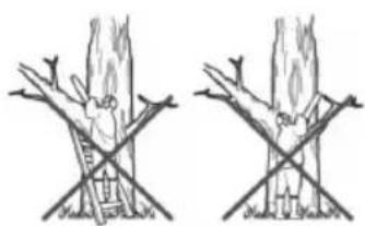
natural_image
Two hand-drawn diagrams showing a person climbing a ladder and another climbing a tree trunk, both crossed by diagonal lines (no text or symbols)Obrezivanje
Najprije režite odozdo prema gore, a zatim od vrha prema dolje.

UPOZORENJE!
natural_image
Exploded view diagram of a mechanical device showing internal components and housing (no text or labels)
natural_image
Hand holding a small electronic device with a spiral coil (no text or symbols visible)
UPOZORENJE!
Prije svakog čišćenja, inspekcije ili popravka uređaja morate se uvjeriti da je motor isključen i da se je ohladio. Da biste izbjegli neželjeno paljenje, odspojite svjećicu.
Poštujte upute za redovito održavanje, pripreme prije upotrebe i svakodneno rutinsko održavanje. Nestručno održavanje može dovesti o teških oštećenja na uređaju.
natural_image
Technical line drawing of a mechanical device with labeled parts (1), showing internal components and no readable text or symbols.natural_image
Line drawing of a hand holding a tool, with no visible text or symbols3. Vodilica (mač)
natural_image
Technical line drawing of a vehicle engine bay with internal components (no text or symbols)Redoviti radovi održavanja
1. Rebra cilindra
Nakupine prašine između rebara cilindra dovode do pregrijavanja motora. Redovito provjeravajte i čistite rebra cilindra; u tu svrhu treba ukloniti filtar za zrak i pokrov cilindra. Prilikom montaže pokrova cilindra pazite da žice i čahure prekidača budu ispravno umetnute.
natural_image
Technical line drawing of a mechanical device with hands operating it (no text or symbols visible)2. Filtar za gorivo
natural_image
Simple line drawing of a hammer striking a tree stump (no text or symbols)
natural_image
Simple line drawing of a mechanical clamp or bracket (no text or symbols)Lanac pile

UPOZORENJE!
Za neometan, siguran rad članci lanca moraju biti oštri.
Naknadno oštrenje je potrebno ako:
- piljevina postane poput finog praha
■ uvođenje pile zahtijeva više snage
rez nije ravan
se pojačaju vibracije
se poveća potrošnja goriva.
Propisi za podešavanje članaka lanca:

UPOZORENJE!
Nosite zaštitne rukavice.
Prije turpijanja:
text_image
Safety warning illustration showing five different methods to avoid using a sandal lamp, including no protection and no tool.text_image
Technical diagram of a chain-linking device with numbered parts for identificationnatural_image
Illustration of a hand using a chain-linking tool to lift a tree branch (no text or symbols)natural_image
Illustration of a fuel being poured into a gas cylinder with an oil pump icon (no text or symbols)PALIWO
natural_image
Illustration of a no-smoking cigarette crossed out of a campfire (no text or symbols)
OSTRZEŻENIE!
text_image
chain oil
text_image
Technical diagram of a tracked vehicle with labeled parts 1 and 2
text_image
3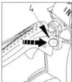
text_image
4
text_image
5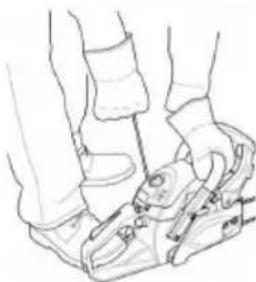
natural_image
Line drawing of a person's legs and feet wearing a high-visibility athletic shoe (no text or symbols)
natural_image
Technical line drawing of a mechanical device with directional arrows indicating motion (no text or symbols)WŁĄCZENIE SILNIKA
natural_image
Line drawing of a person's legs and feet wearing athletic shoes, with no visible text or symbols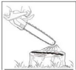
natural_image
Illustration of a hand using a long-handled tool to lift a tree stump (no text or symbols)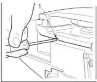
natural_image
Technical line drawing of a mechanical assembly with no visible text or symbols
OSTRZEŻENIE!
text_image
Diagram illustrating a manual logging process with a chainsaw and tree stump, showing gear movement and cutting steps.
OSTRZEŻENIE!
text_image
(a) (1) (2)text_image
(b) (1) (3)natural_image
Prohibition sign showing a diagonal slash over a pipe, enclosed in a circle (no text or symbols)natural_image
Illustration of a person using a power tool to cut a circular object with a hand, showing motion direction (no text or symbols)natural_image
Illustration of a person using a power tool to cut a circular object with a curved arrow indicating rotation (no text or symbols)natural_image
Illustration of a hand using a power tool to cut a circular object, with an arrow indicating rotation (no text or symbols)natural_image
Simple line drawing of a ground surface with a downward arrow indicating a point of interest (no text or symbols)
OSTRZEŻENIE!
text_image
Diagram illustrating a mechanical or physical process with labeled arrows and components, possibly depicting a moving cart or tool path.text_image
Diagram illustrating airflow around a turbine blade with labeled components and directional arrows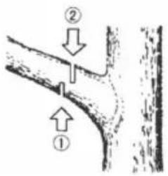
text_image
Diagram showing two labeled arrows pointing to a curved structure with annotations ① and ②
natural_image
Two identical line drawings of a tree with branches and leaves, showing no text or symbols.natural_image
Exploded view diagram of a mechanical device showing internal components and housing (no text or labels)
OSTRZEŻENIE!
natural_image
Hand holding a small object with a spiral arrow, no visible text or symbols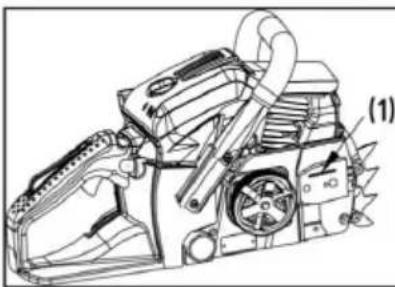
natural_image
Technical line drawing of a mechanical device with gears and levers (no text or symbols)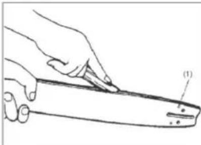
natural_image
Line drawing of a hand holding a tool, with no visible text or symbols
text_image
(2) (3)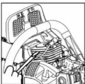
natural_image
Technical line drawing of a vehicle's internal components (no text or symbols)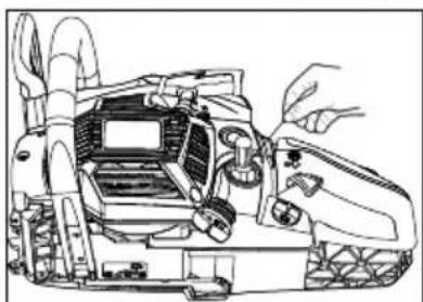
natural_image
Technical line drawing of a mechanical device with no visible text or symbolsnatural_image
Simple line drawing of a saw cutting into a tree stump (no text or symbols)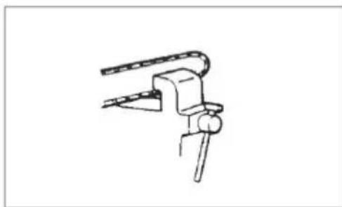
natural_image
Simple line drawing of a mechanical clamp or bracket assembly (no text or symbols)Łańcuch tnący

OSTRZEŻENIE!
text_image
Technical diagram of a chain-linking device with numbered parts for identificationtext_image
(11) (13)natural_image
Illustration of a hand using a chain to cut a tree branch with arrows indicating direction (no text or symbols)PALIVO A ŘETĚZOVÝ OLEJ
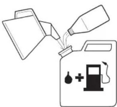
natural_image
Illustration of a fuel being poured into a gas cylinder with an oil pump icon (no text or symbols)PALIVO
natural_image
Illustration of a no-smoking cigarette crossed out of a campfire (no text or symbols)
VAROVÁNÍ!
text_image
chain oil
text_image
Technical diagram of a tracked vehicle with labeled parts 1 and 2
natural_image
Technical diagram of a mechanical assembly with no visible text or symbols
text_image
4
text_image
5
natural_image
Line drawing of a person's legs and feet wearing a high-lying shoe (no text or symbols)
natural_image
Technical line drawing of a mechanical device with directional arrows indicating motion (no text or symbols)ZAPNUTÍ MOTORU
natural_image
Line drawing of a person's legs and feet wearing a high-heeled shoe (no text or symbols)
VAROVÁNÍ!
natural_image
Illustration of a hand using a tool to lift a tree stump on grass (no text or symbols)KONTROLA PŘÍVODU OLEJE
natural_image
Line drawing of a hand using a tool to adjust or install a mechanical component (no text or symbols present)natural_image
Illustration of a person using a chainsaw to cut tree bark (no text or symbols)
text_image
(a) (1) (2)
text_image
(b) (1) (3)
text_image
(1) (2) (3)
VAROVÁNÍ!
natural_image
Symbol of a crossed saw cutting through pipes, enclosed in a circle (no text or labels)
VAROVÁNÍ!
natural_image
Illustration of a person using a saw to cut a circular object with a hand, showing motion direction (no text or symbols)natural_image
Illustration of a person using a tool to lift a large cylindrical object, with an arrow indicating rotation (no text or symbols)natural_image
Illustration of a person using a cart to lift a ball, with an arrow indicating motion (no text or symbols)natural_image
Simple line drawing of a rectangular object with a downward arrow above it, no text or symbols present.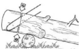
natural_image
Simple line drawing of a log being cut with arrows indicating direction, no text or symbols present
text_image
Diagram illustrating a mechanical or physical setup with labeled components and directional arrows, possibly depicting a moving or rotating system.
text_image
Diagram illustrating airflow around a tree trunk with labeled arrows and directional arrowstext_image
Diagram showing two labeled arrows pointing to a structural component or feature, with numbers ① and ② indicating directional relationships.Krácení
natural_image
Two hand-drawn diagrams showing a person climbing a ladder and another climbing a tree trunk, both crossed by diagonal lines (no text or symbols)
VAROVÁNÍ!
natural_image
Exploded view diagram of a mechanical device showing internal components and housing (no text or labels)
VAROVÁNÍ!
natural_image
Hand holding a small object with a spiral arrow, no visible text or symbolsnatural_image
Technical line drawing of a mechanical device with labeled parts (1), showing internal components and no readable text or symbols.2. Přípojka oleje
natural_image
Line drawing of a hand holding a tool with a labeled part (1), no text or symbols present3. Vodicí lišta
natural_image
Technical line drawing of a vehicle engine compartment showing internal components like gears and motors (no text or labels)natural_image
Technical line drawing of a mechanical device with hands operating it (no text or symbols present)2. Palivový filtr
natural_image
Simple line drawing of a hand using a saw to cut a tree stump (no text or symbols)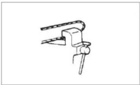
natural_image
Simple line drawing of a mechanical clamp or bracket assembly (no text or symbols)Řetěz

VAROVÁNÍ!
text_image
Safety warning illustration showing various methods to avoid a device, including foot protection and no-smoking.text_image
Technical diagram of a chain-linking device with numbered parts for identificationnatural_image
Illustration of a hand using a chain-linking tool to lift a tree branch (no text or symbols)PALIVO A REŤAZOVÝ OLEJ

natural_image
Illustration of a fuel being poured into a container with an oil pump icon (no text or symbols)PALIVO
natural_image
Illustration of a no-smoking cigarette crossed out of a campfire (no text or symbols)
VAROVANIE!
text_image
chain oil
text_image
Technical diagram of a tracked vehicle with labeled parts 1 and 2
text_image
Technical diagram showing mechanical assembly with labeled components and directional arrows
text_image
4
text_image
5
natural_image
Line drawing of a person's legs and feet wearing a high-visibility cleat (no text or symbols)
natural_image
Technical line drawing of a mechanical device with directional arrows indicating motion (no text or symbols)ZAPNUTIE MOTORA
natural_image
Line drawing of a person's legs and feet wearing athletic shoes (no text or symbols)
VAROVANIE!
natural_image
Illustration of a hand using a tool to lift a tree stump (no text or symbols)KONTROLA ZÁSOBOVANIA OLEJOM
natural_image
Line drawing of a hand using a tool to cut or adjust a mechanical component (no text or symbols present)text_image
Diagram illustrating a manual logging process with a chainsaw and tree stump, showing gear and cutting steps.
VAROVANIE!
text_image
(a) (1) (2)
text_image
(b) (1) (3)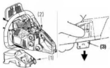
text_image
(1) (2) (3)PREPÍNANIE PREVÁDZKOVÝCH REŽIMOV
natural_image
Prohibition sign showing a diagonal slash over a pipe, enclosed in a circle (no text or symbols)natural_image
Illustration of a hand using a tool to cut a circular object with a curved arrow indicating rotation (no text or symbols)natural_image
Illustration of a person using a power tool to cut a circular object with a curved arrow indicating rotation (no text or symbols)natural_image
Illustration of a person using a power tool to cut a circular object, with an arrow indicating rotation (no text or symbols)natural_image
Simple line drawing of a ground surface with a downward arrow indicating a drop or fall (no text or symbols)text_image
Diagram illustrating a logging or tree clearing scene with labeled components and directional arrows indicating movement.text_image
Diagram illustrating a logging or drilling process with labeled components and directional arrowstext_image
Diagram illustrating airflow around a cylindrical object with labeled parts ① and ②, showing directional arrows.
VAROVANIE!
text_image
Diagram showing two labeled arrows pointing to a curved structure with annotations ① and ②
natural_image
Two identical line drawings of a tree with branches and leaves, showing no text or symbols.Skracovanie
Najprv režte zdola nahor, potom od špičky smerom dolu.

VAROVANIE!
natural_image
Exploded view diagram of a mechanical device showing internal components and housing (no text or labels)
natural_image
Hand holding a small object with a spiral arrow, no visible text or symbols
VAROVANIE!
natural_image
Technical line drawing of a mechanical device with labeled parts (1), showing internal components and no readable text or symbols.2. Olejová prípojka
natural_image
Illustration of a hand holding a tool with a labeled part (1), no text or symbols present3. Vodiaca lišta
natural_image
Technical diagram of a vehicle's internal components, possibly engine or motor assembly (no text or labels visible)natural_image
Technical line drawing of a mechanical device with hands operating it (no text or symbols present)2. Palivový filter
natural_image
Simple line drawing of a saw cutting into a tree stump (no text or symbols)
natural_image
Simple line drawing of a mechanical clamp or bracket (no text or symbols)Ret'az

VAROVANIE!
text_image
Technical diagram of a chain-linking device with numbered parts for identificationnatural_image
Illustration of a hand using a chain-linking tool to lift a chain, showing motion arrows (no text or symbols)ÜZEMANYAG ÉS LÁNCKENŐ OLAJ
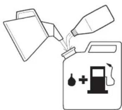
natural_image
Illustration of a fuel being poured into a gas cylinder with an oil pump icon (no text or symbols)ÜZEMANYAG
natural_image
Illustration of a no-smoking cigarette crossed out of a campfire (no text or symbols)
FIGYELMEZTETÉS!
text_image
chain oil
text_image
Technical diagram of a tracked vehicle with labeled parts 1 and 2
natural_image
Technical diagram of a mechanical assembly with no visible text or symbols
text_image
4
text_image
5
natural_image
Line drawing of a person's legs and feet wearing a small mechanical device (no text or symbols)
natural_image
Technical line drawing of a mechanical device with directional arrows indicating motion (no text or symbols)A MOTOR BEKAPCSOLÁSA
natural_image
Line drawing of a person using a foot switch device (no text or symbols)
FIGYELMEZTETÉS!
natural_image
Line drawing of a hand using a tool to lift a tree stump (no text or symbols)OLAJELLÁTÁS ELLENŐRZÉSE
natural_image
Technical line drawing of a mechanical component with a hand operating a tool (no text or symbols present)natural_image
Illustration of a person using a chainsaw to cut tree bark (no text or symbols)
text_image
(a) (1) (2)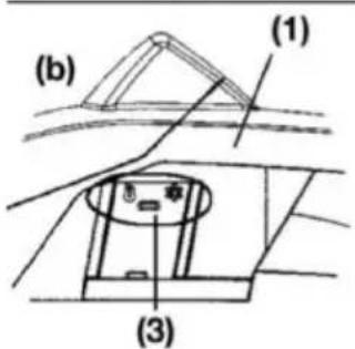
text_image
(b) (1) (3)
text_image
(1) (2) (3)
FIGYELMEZTETÉS!
natural_image
Prohibition sign showing a diagonal slash over a pipe with a diagonal bar, enclosed in a circle (no text or symbols)
FIGYELMEZTETÉS!
natural_image
Illustration of a person using a power tool to cut a circular object with a rotating arrow (no text or symbols)natural_image
Illustration of a person using a tool to lift a large cylindrical object, with an arrow indicating motion (no text or symbols)natural_image
Illustration of a person using a cart to lift a ball, with an arrow indicating motion (no text or symbols)natural_image
Illustration of a mechanical component with circular holes and a curved blade (no text or symbols)natural_image
Simple line drawing of a rectangular block with a downward arrow, no text or symbols present
text_image
Diagram illustrating a logging process with arrows indicating direction and a circular object labeled '10' near the ground.
text_image
Diagram illustrating a logging or drilling process with labeled components and directional arrows, likely for surveying or measuring.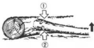
text_image
Diagram illustrating airflow around a turbine blade with labeled components and directional arrowstext_image
Diagram showing two labeled arrows pointing to a curved structure, with numbers ① and ② indicating directional relationships.Fa tetejezése
natural_image
Two hand-drawn diagrams showing a tree with branches and a ladder, no text or symbols present.
FIGYELMEZTETÉS!
natural_image
Exploded view diagram of a mechanical device showing internal components and housing (no text or labels)
FIGYELMEZTETÉS!
natural_image
Hand holding a small electronic device with a scroll wheel, no visible text or symbolsnatural_image
Technical line drawing of a mechanical device with labeled parts (1), showing internal components and no readable text or symbols.2. Olajcsatlakozó
natural_image
Line drawing of a hand holding a tool with a labeled part (1), no text or symbols presentnatural_image
Technical line drawing of a car engine bay with visible internal components and no text or symbolsnatural_image
Technical line drawing of a mechanical device with hands operating it (no text or symbols present)2. Üzemanyagszürő
natural_image
Simple line drawing of a hand holding a tool next to a rock (no text or symbols)
natural_image
Simple line drawing of a mechanical clamp or bracket assembly (no text or symbols)Fürészlánc

FIGYELMEZTETÉS!
Delenes placering....260
Symboler på maskinen.... 261
Sikker betjening....263
text_image
Illustration showing various safety symbols including a hand holding a flip, a diagonal line with a diagonal marker, and a crossed-out circle with a diagonal line.text_image
Technical diagram of a chain-linking device with numbered parts for identificationnatural_image
Illustration of a hand using a chain-to-hand tool to cut a chain, showing motion arrows (no text or symbols)natural_image
Illustration of a fuel being poured into a container with an oil pump icon (no text or symbols)BRÆNDSTOF
natural_image
Illustration of a no-smoking cigarette crossed out of a campfire (no text or symbols)
ADVARSEL!
text_image
chain oil
text_image
Technical diagram of a tracked vehicle with labeled parts 1 and 2
text_image
Technical diagram showing mechanical assembly with labeled parts and directional arrows indicating motion or force directions.
text_image
4
text_image
5
natural_image
Line drawing of a person's legs and feet wearing a high-visibility athletic shoe (no text or symbols)
natural_image
Mechanical device diagram showing a lever mechanism with directional arrows (no text or symbols)START AF MOTOREN
natural_image
Line drawing of two hands using a brake pedal (no text or symbols)
ADVARSEL!
natural_image
Illustration of a hand using a tool to lift a tree stump (no text or symbols)KONTROL AF OLIEFORSYNINGEN
natural_image
Technical line drawing of a hand operating a mechanical component (no text or symbols)text_image
Diagram illustrating a manual logging process with a chainsaw and tree stump, showing gear movement and cutting steps.
ADVARSEL!
text_image
(a) (1) (2)text_image
(b) (1) (3)natural_image
Prohibition sign showing a diagonal slash over a pipe, enclosed in a circle (no text or symbols)
ADVARSEL!
natural_image
Illustration of a hand using a saw to cut a circular object with a rotating arrow (no text or symbols)natural_image
Illustration of a hand using a tool to lift a circular object, with an arrow indicating rotation (no text or symbols)natural_image
Illustration of a hand using a tool to cut a circular object, with an arrow indicating rotation (no text or symbols)natural_image
Simple line drawing of a ground level with a downward arrow indicating a drop or fall (no text or symbols)text_image
Diagram illustrating a logging or logging process with labeled components and directional arrows indicating movement.text_image
Diagram illustrating a mechanical or physical process with labeled arrows and circular components, possibly indicating forces or motion.text_image
Diagram illustrating fluid flow around a cylindrical object with labeled parts ① and ②, showing streamlines and directional arrows.text_image
Diagram showing two labeled arrows pointing to a curved structure with annotations ① and ②
natural_image
Two identical line drawings of a tree with branches and leaves, showing no text or symbols.Beskæring
natural_image
Exploded view diagram of a mechanical device showing internal components and housing (no text or labels)
natural_image
Hand holding a small object with a spiral arrow, no text or symbols visible
ADVARSEL!
natural_image
Technical line drawing of a mechanical device with labeled parts (1), showing internal components and no readable text or symbols.2. Smøreåbning
natural_image
Illustration of a hand holding a tool with a labeled component (1), no text or symbols present3. Sværd
natural_image
Technical diagram of a vehicle engine bay with no visible text or symbolsnatural_image
Technical line drawing of a mechanical device with no visible text or symbols2. Brændstofffilter
natural_image
Simple line drawing of a saw cutting into a tree stump (no text or symbols)
natural_image
Simple line drawing of a mechanical clamp or bracket (no text or symbols)Savkæde

ADVARSEL!
text_image
Technical diagram of a chain-linking device with numbered parts for identificationnatural_image
Illustration of a hand using a chain-linking tool to interact with a gear (no text or symbols present)BRÄNSLE OCH KEDJEOLJA

natural_image
Illustration of a fuel being poured into a gas cylinder with an oil pump icon (no text or symbols)BRÄNSLE
natural_image
Illustration of a no-smoking cigarette crossed out of a campfire (no text or symbols)
WARNING!
text_image
chain oil
text_image
Technical diagram of a tracked vehicle with labeled parts 1 and 2
natural_image
Technical diagram of a mechanical assembly with no visible text or symbols
text_image
4
text_image
5
natural_image
Line drawing of a person's legs and feet wearing a small mechanical device (no text or symbols)
natural_image
Technical line drawing of a mechanical device with directional arrows indicating motion (no text or symbols)STARTA MOTORN
natural_image
Line drawing of a person using a foot switch device (no text or symbols)
WARNING!
natural_image
Line drawing of a hand using a long-handled tool to lift a rock with a small pile (no text or symbols)KONTROLL AV OLJETILLFÖRSEL
natural_image
Line drawing of a hand using a tool to adjust or install a mechanical component (no text or symbols present)natural_image
Illustration of a person using a chainsaw to cut tree bark (no text or symbols)
text_image
(a) (1) (2)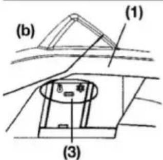
text_image
(b) (1) (3)
text_image
(1) (2) (3)
WARNING!
natural_image
Prohibition sign showing a diagonal slash over a pipe, enclosed in a circle (no text or symbols)
WARNING!
natural_image
Illustration of a person using a power tool to cut a circular object with a rotating arrow (no text or symbols)natural_image
Illustration of a person using a power tool to cut a circular object, with an arrow indicating rotation (no text or symbols)natural_image
Illustration of a hand using a tool to lift a ball on a rolling surface, with an arrow indicating rotation (no text or symbols)Skydd mot kast
natural_image
Illustration of a mechanical component with circular holes and a curved blade (no text or symbols)Fälla ett träd

natural_image
Simple line drawing of a rectangular object with a downward arrow above it, no text or symbols present.
natural_image
Simple line drawing of a wooden log being cut with arrows indicating force or movement, no text or symbols present.
text_image
Diagram illustrating a logging or drilling process with labeled components and directional arrows, likely for surveying or monitoring.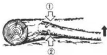
text_image
Diagram illustrating airflow around a circular object with labeled parts ① and ②, showing directional arrows.text_image
Diagram showing two labeled arrows pointing to a curved structure, with numbers ① and ② indicating directional relationships.Beskärning
natural_image
Two hand-drawn diagrams showing a person climbing a ladder and another climbing a tree trunk, both crossed by diagonal lines (no text or symbols)
WARNING!
natural_image
Exploded view diagram of a mechanical device showing internal components and housing (no text or labels)
WARNING!
natural_image
Hand holding a small object with a spiral arrow, no text or symbols visiblenatural_image
Technical line drawing of a mechanical device with labeled parts (1), showing internal components and no readable text or symbols.natural_image
Line drawing of a hand holding a tool with a labeled part (1), no text or symbols present3. Svärd
natural_image
Technical diagram of a vehicle's internal engine compartment showing hoses and structural components (no text or labels)natural_image
Technical line drawing of a mechanical device with hands operating it (no text or symbols present)2. Bränslefilter
natural_image
Simple line drawing of a hand using a tool to cut a tree stump (no text or symbols)
natural_image
Simple line drawing of a mechanical clamp or bracket (no text or symbols)Sågkedja

WARNING!
Delenes plassering....306
Symboler på maskinen.... 306
For sikker drift....309
text_image
Illustration showing various safety symbols including a hand holding a slide, a diagonal line, a crossed-out circle, and a crossed-out rectangle.text_image
Technical diagram of a chain-linking device with numbered parts for identificationnatural_image
Illustration of a hand using a chain-to-hand tool to cut a chain, showing motion arrows (no text or symbols)DRIVSTOFF OG KJEDEOLJE

natural_image
Illustration of a fuel being poured into a gas cylinder with an oil pump icon (no text or symbols)DRIVSTOFF
natural_image
Illustration of a no-smoking cigarette crossed out of a campfire (no text or symbols)
ADVARSEL!
text_image
chain oil
text_image
Technical diagram of a tracked vehicle with labeled parts 1 and 2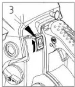
text_image
Technical diagram showing mechanical assembly with labeled parts and directional arrows indicating motion or flow
text_image
4
text_image
5
natural_image
Line drawing of a person's legs and feet wearing a high-visibility athletic shoe (no text or symbols)
natural_image
Mechanical device diagram showing a lever mechanism with directional arrows (no text or symbols)STARTE MOTOREN
natural_image
Line drawing of two hands using a foot switch to lift a small object (no text or symbols)
ADVARSEL!
Før du starter motoren, må du forsikre deg om at kjeden ikke kommer i kontakt med noe som helst. Forsikre deg om at kjedebremsen alltid er aktivert før hver start.

natural_image
Illustration of a hand using a tool to lift a tree stump (no text or symbols)SJEKKE OLJETILF∅RSELEN
natural_image
Technical line drawing of a mechanical assembly with a hand operating a tool (no text or symbols present)text_image
Diagram illustrating a manual tree stumping process with labeled components and directional arrows
ADVARSEL!
text_image
(a) (1) (2)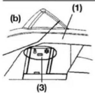
text_image
(b) (1) (3)
text_image
(2) (1) Y (3)HVORDAN SKIFTE MELLOM DRIFTSMODUSER
natural_image
Prohibition sign showing a diagonal slash over a pipe, enclosed in a circle (no text or symbols)
ADVARSEL!
natural_image
Illustration of a hand using a saw to cut a circular object with a rotating arrow (no text or symbols)natural_image
Illustration of a hand using a tool to lift a circular object, with an arrow indicating rotation (no text or symbols)natural_image
Illustration of a person using a tool to cut a ball on a cutting board, with an arrow indicating motion (no text or symbols)natural_image
Simple line drawing of a ground surface with a downward arrow indicating a drop or fall (no text or symbols)text_image
Diagram illustrating a logging or tree clearing scene with labeled arrows and a circular object, likely illustrating a physical or geological process.text_image
Diagram illustrating a logging or drilling process with labeled components and directional arrows, including a tool and ground symbols.Kviste et felt tre
text_image
Diagram illustrating airflow or heat transfer between two circular objects with numbered arrows indicating direction of movement.
ADVARSEL!
text_image
Diagram showing two labeled arrows pointing to a curved structure with annotations ① and ②
natural_image
Two identical line drawings of a tree with branches and leaves, showing no text or symbols.Kvisting
natural_image
Exploded view diagram of a mechanical device showing internal components and housing (no text or labels)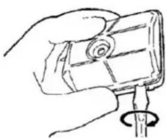
natural_image
Hand holding a small object with a spiral arrow, no text or symbols visible
ADVARSEL!
natural_image
Technical line drawing of a mechanical device with labeled parts (1), showing internal components and no readable text or symbols.2. Oljeåpning
natural_image
Illustration of a hand holding a tool with a labeled part (1), no text or symbols present3. Sverd
natural_image
Technical diagram of an internal combustion engine compartment with no visible text or symbolsnatural_image
Technical line drawing of a mechanical device with no visible text or symbols2. Drivstofffilter
(a) Bruk en ledningskrok til å ta filteret ut av fylleåpningen.
(1) Drivstofffilter
(b) Demonter filteret og vask det, eller bytt i et nytt hvis det er nødven-dig.

ADVARSEL!
VEDLIKEHOLD AV SAGKJEDE OG SVERD
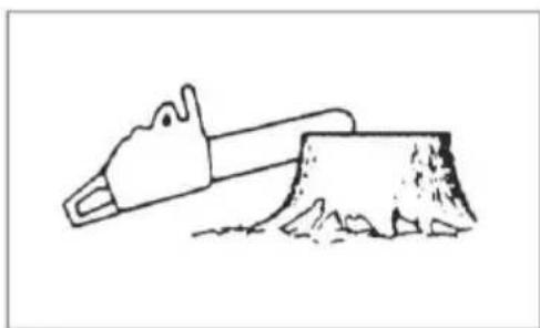
natural_image
Simple line drawing of a saw cutting into a tree stump (no text or symbols)
natural_image
Simple line drawing of a mechanical clamp or bracket assembly (no text or symbols)Sagkjede

ADVARSEL!
MOOTTORISAHAN SYMBOLIT
text_image
Technical diagram of a chain-linking device with numbered parts for identificationnatural_image
Illustration of a hand using a chain-linking tool to lift a tree branch (no text or symbols)POLTTOAINE JA TERÄKETJUÖLJY

natural_image
Illustration of a fuel being poured into a gas cylinder with an oil pump icon (no text or symbols)POLTTOAINE
natural_image
Illustration of a no-smoking cigarette crossed out of a campfire (no text or symbols)
VAROITUS!
text_image
chain oil
text_image
Technical diagram of a tracked vehicle with labeled parts 1 and 2
text_image
3
text_image
4
text_image
5
natural_image
Line drawing of a person's legs and feet wearing a small mechanical device (no text or symbols)
natural_image
Technical line drawing of a mechanical device with directional arrows indicating motion (no text or symbols)MOOTTORIN KÄYNNISTÄMINEN
natural_image
Line drawing of a person's legs and feet wearing a small mechanical device (no text or symbols)
VAROITUS!
natural_image
Line drawing of a hand using a tool to lift a tree stump (no text or symbols)TERÄKETJUVOITELUN TARKISTAMINEN
natural_image
Line drawing of a hand using a tool to adjust or install a mechanical component (no text or symbols present)KYTKIMEN TOIMINNAN TARKISTAMINEN
natural_image
Illustration of a person using a chainsaw to cut tree bark (no text or symbols)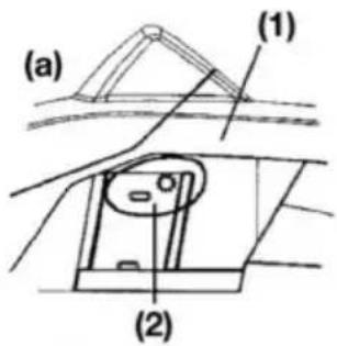
text_image
(a) (1) (2)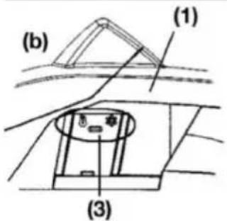
text_image
(b) (1) (3)
text_image
(1) (2) (3)
VAROITUS!
natural_image
Prohibition sign showing a diagonal slash over a pipe with a diagonal bar, enclosed in a circle (no text or symbols)
VAROITUS!
natural_image
Illustration of a person using a power tool to cut a circular object with a rotating arrow (no text or symbols)natural_image
Illustration of a person using a power tool to cut a circular object, with an arrow indicating rotation (no text or symbols)natural_image
Illustration of a person using a cart to lift a ball, with an arrow indicating motion (no text or symbols)natural_image
Simple line drawing of a rectangular object with a downward arrow above it, no text or symbols present.
natural_image
Simple line drawing of a wooden log being pulled by a rope, with arrows indicating motion direction (no text or symbols)
text_image
Diagram illustrating a logging or drilling process with labeled components and directional arrows, likely for surveying or monitoring.
text_image
Diagram illustrating airflow around a circular object with labeled parts ① and ②, showing directional arrows.text_image
Diagram showing two labeled arrows pointing to a pipe or channel, with numbers ① and ② indicating directional flow.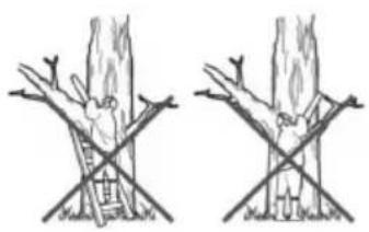
natural_image
Two hand-drawn diagrams showing a tree with branches and leaves, no text or symbols present.natural_image
Exploded view diagram of a mechanical device showing internal components and housing (no text or labels)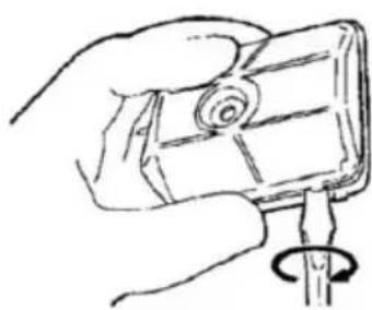
natural_image
Hand holding a small object with a spiral arrow, no visible text or symbols
VAROITUS!
natural_image
Technical line drawing of a mechanical device with gears and components (no text or symbols)2. Öljyportti
natural_image
Line drawing of a hand holding a tool, with no visible text or symbols3. Terälaippa
natural_image
Technical diagram of a vehicle engine bay with internal components and no visible text or symbolsMääräaikaishuollot
natural_image
Technical line drawing of a mechanical device with hands operating it (no text or symbols visible)natural_image
Simple line drawing of a hammer striking a tree stump (no text or symbols)
natural_image
Simple line drawing of a mechanical clamp or bracket (no text or symbols)Teräketju

VAROITUS!
Hampaiden standardit:

VAROITUS!
text_image
Illustration showing five different types of safety measures: manual hand, flat tool, no clear sign, no clear sign, and closed eye.text_image
Technical diagram of a chain-linking device with numbered parts for identificationnatural_image
Illustration of a hand using a chain-to-hand tool to cut a chain, showing motion arrows (no text or symbols)KÜTUS JA KETIÖLI

natural_image
Illustration of a fuel being poured into a gas cylinder with an oil pump icon (no text or symbols)KÜTUS
natural_image
Illustration of a campfire with a no-smoking cigarette and smoke, symbolizing noise or fire (no text present)
HOIATUS!
text_image
chain oil
text_image
Technical diagram of a tracked vehicle with labeled parts 1 and 2
text_image
3
text_image
4
text_image
5
natural_image
Line drawing of a person's legs and feet wearing a high-visibility shoe (no text or symbols)
natural_image
Mechanical device with directional arrows indicating motion or movement (no text or symbols)MOOTORI SISSELÜLITAMINE
natural_image
Line drawing of a person's legs and feet wearing athletic shoes, with no visible text or symbols
HOIATUS!
natural_image
Illustration of a hand using a tool to lift a tree stump (no text or symbols)KONTROLLIGE ÖLIVARUSTUST
natural_image
Technical line drawing of a hand using a tool to cut or adjust a mechanical component (no text or symbols present)text_image
Diagram showing a person using a chainsaw to cut tree bark, with Chinese labels indicating the process.
HOIATUS!
text_image
(a) (1) (2)
text_image
(b) (1) (3)
text_image
(1) (2) (3)TÖÖREŽIIMI ÜMBERLÜLITAMINE
natural_image
Prohibition sign showing a diagonal slash over a pipe, crossed out by a diagonal line (no text or symbols)
HOIATUS!
natural_image
Illustration of a hand using a saw to cut a circular object with a rotating arrow (no text or symbols)natural_image
Illustration of a hand using a tool to lift a circular object, with an arrow indicating rotation (no text or symbols)natural_image
Illustration of a hand using a tool to cut a circular object, with an arrow indicating rotation (no text or symbols)Tagasilöögikaitse
natural_image
Simple line drawing of a ground surface with a downward arrow indicating a drop or fall (no text or symbols)text_image
Diagram illustrating a logging or deforestation process with labeled arrows and a circular object, likely depicting environmental change or resource use.text_image
Diagram illustrating a physics experiment with labeled components and directional arrows, likely from an optics or mechanics problem.text_image
Diagram illustrating airflow around a cylindrical object with labeled parts ① and ②, showing directional arrows.
HOIATUS!
text_image
Diagram showing two labeled arrows pointing to a curved structure with annotations ① and ②
natural_image
Two hand-drawn diagrams showing tree branches with leaves and a person climbing, no text or symbols present.Järkamine
natural_image
Exploded view diagram of a mechanical device showing internal components and housing (no text or labels)
natural_image
Hand holding a small electronic device with a spiral coil (no text or symbols visible)
HOIATUS!
natural_image
Technical line drawing of a mechanical device with labeled parts (1), showing internal components and no readable text or symbols.2. Ölinippel
natural_image
Line drawing of a hand holding a tool, with no visible text or symbolsnatural_image
Technical line drawing of a car engine bay with visible internal components and no text or symbolsnatural_image
Technical line drawing of a mechanical device with no visible text or symbols2. Kütusefilter
natural_image
Simple line drawing of a saw cutting into a tree stump (no text or symbols)
natural_image
Simple line drawing of a mechanical clamp or bracket assembly (no text or symbols)Saekett

HOIATUS!
DARBO SAUGOS NURODYMAI
text_image
Technical diagram of a chain-linking device with numbered parts for identificationtext_image
(11) (13)natural_image
Illustration of a hand using a chain to interact with a mechanical device (no text or symbols visible)DEGALAI IR GRANDINÉS ALYVA

natural_image
Illustration of a fuel being poured into a gas cylinder with an oil pump icon (no text or symbols)DEGALAI
natural_image
Illustration of a no-smoking cigarette crossed out of a campfire (no text or symbols)
DÈMESIO!
text_image
chain oil
text_image
Technical diagram of a tracked vehicle with labeled parts 1 and 2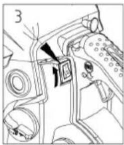
natural_image
Technical diagram of a mechanical assembly with no visible text or symbols
text_image
4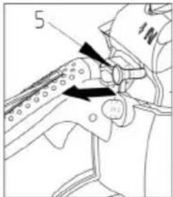
text_image
5
natural_image
Line drawing of a person's legs and feet wearing a high-visibility cleat (no text or symbols)
natural_image
Technical line drawing of a mechanical device with directional arrows indicating motion (no text or symbols)VARIKLIO IJUNGIMAS
natural_image
Line drawing of a person's legs and feet wearing a high-heeled shoe (no text or symbols)
DÈMESIO!
natural_image
Line drawing of a hand using a tool to lift a tree stump (no text or symbols)ALYVOS TIEKIMO PATIKRINIMAS
natural_image
Technical line drawing of a mechanical component with a hand operating a tool (no text or symbols present)natural_image
Illustration of a person using a chainsaw to cut tree bark (no text or symbols)
text_image
(a) (1) (2)
text_image
(b) (1) (3)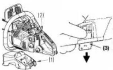
text_image
(1) (2) (3)
DÈMESIO!
natural_image
Prohibition sign showing a diagonal slash over a pipe, enclosed in a circle (no text or symbols)
DÈMESIO!
natural_image
Illustration of a hand using a tool to cut a circular object with a rotating arrow (no text or symbols)natural_image
Illustration of a person using a power tool to cut a circular object with a curved arrow indicating rotation (no text or symbols)natural_image
Illustration of a person using a cart to cut a ball, with an arrow indicating motion (no text or symbols)natural_image
Illustration of a mechanical component with circular ports and a curved blade (no text or symbols)Kirtimas
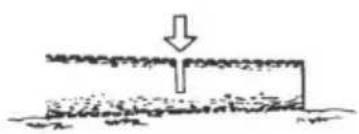
natural_image
Simple line drawing of a ground surface with a downward arrow indicating a drop or fall (no text or symbols)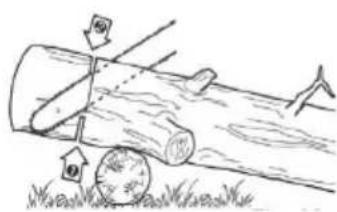
text_image
Diagram illustrating a logging or timber cutting process with labeled arrows and scale indicators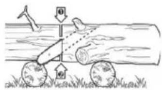
text_image
Diagram illustrating a mechanical or physical setup with labeled components and directional arrows, likely depicting a moving cart or tool path.
text_image
Diagram illustrating airflow around a tree trunk with labeled parts and directional arrowstext_image
Diagram showing two labeled arrows pointing to a pipe or channel structure with annotations ① and ②.
natural_image
Two hand-drawn diagrams showing a person climbing a ladder and another climbing a tree trunk, both without any text or symbols.Genéjimas
natural_image
Technical line drawing of a mechanical device with exploded view (no text or symbols)
natural_image
Hand holding a small object with a spiral arrow, no visible text or symbols
DÉMESIO!
natural_image
Technical line drawing of a mechanical device with gears and housing (no text or symbols)2. Alyvos jungtis
natural_image
Line drawing of a hand holding a tool, with no visible text or symbolsnatural_image
Technical line drawing of a vehicle engine bay with internal components (no text or symbols)natural_image
Technical line drawing of a mechanical device with hands operating it (no text or symbols visible)2. Degalų filtras
natural_image
Simple line drawing of a hand using a tool to cut a tree stump (no text or symbols)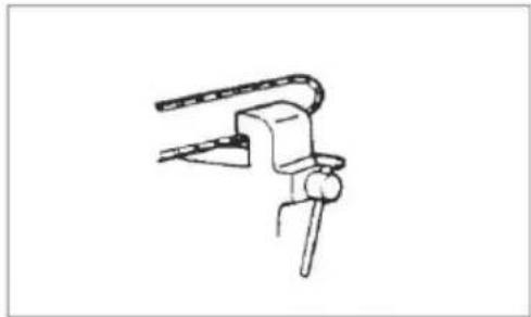
natural_image
Simple line drawing of a mechanical clamp or bracket (no text or symbols)Pjovimo grandinė

DÈMESIO!
text_image
Illustration showing five different types of playground equipment including a sander, floor tiles, and no litter.text_image
Technical diagram of a chain-linking device with numbered parts for identificationnatural_image
Illustration of a hand using a chain-linking tool to lift a tree branch (no text or symbols)DEGVIELA UN KËDES ELLA
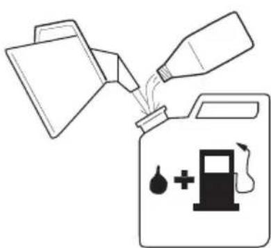
natural_image
Illustration of a fuel being poured into a gas cylinder with an oil pump icon (no text or symbols)DEGVIELA
natural_image
Illustration of a no-smoking cigarette crossed out of a campfire (no text or symbols)
BRĪDINĀJUMS!
text_image
chain oil
text_image
Technical diagram of a tracked vehicle with labeled parts 1 and 2
text_image
Technical diagram showing mechanical assembly with labeled components and directional arrows
text_image
4
text_image
5
natural_image
Line drawing of a person's legs and feet wearing a high-visibility cleat (no text or symbols)
natural_image
Technical line drawing of a mechanical device with directional arrows indicating motion (no text or symbols)MOTORAI EISLÊGŠANA
natural_image
Line drawing of a person's legs and feet wearing athletic shoes, with no visible text or symbols
BRĪDINĀJUMS!
natural_image
Line drawing of a person using a long-handled tool to lift a tree stump (no text or symbols)ELLOŠANAS SISTEMAS PARBAUDE
natural_image
Line drawing of a hand using a tool to adjust or install a mechanical component (no text or symbols present)text_image
Diagram illustrating a manual tree clearing process with labeled components and a downward arrow indicating the process.
BRĪDINĀJUMS!
text_image
(a) (1) (2)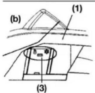
text_image
(b) (1) (3)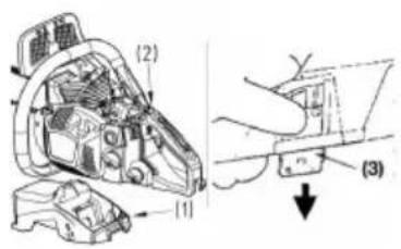
text_image
(1) (2) (3)DARBĪBAS REŽĪMA PĀRSLĒGŠANA
natural_image
Prohibition sign showing a diagonal slash over a pipe, enclosed in a circle (no text or symbols)
BRĪDINĀJUMS!
natural_image
Illustration of a person using a power tool to cut a circular object with a rotating wheel (no text or symbols)natural_image
Illustration of a hand using a tool to lift a circular object, with an arrow indicating rotation (no text or symbols)natural_image
Illustration of a hand using a tool to cut a circular object, with an arrow indicating rotation (no text or symbols)natural_image
Simple line drawing of a ground surface with a downward arrow indicating a drop or fall (no text or symbols)text_image
Diagram showing a wooden log being pulled by a rope, with arrows and numbered labels indicating motion direction.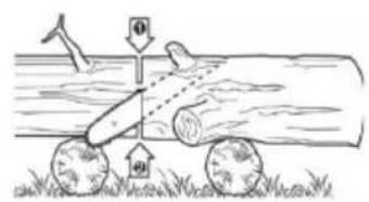
text_image
Diagram illustrating a mechanical or hydraulic system with labeled components and directional arrows, likely depicting a physical or agricultural process.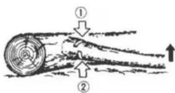
text_image
Diagram illustrating airflow around a cylindrical object with labeled parts ① and ②, showing directional arrows.text_image
Diagram showing two labeled arrows pointing to a curved structure with annotations ① and ②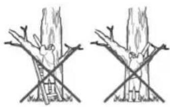
natural_image
Two hand-drawn diagrams showing tree branches with a ladder and crossbones, no text or symbols present.īsināšana
natural_image
Exploded view diagram of a mechanical device showing internal components and housing (no text or labels)
natural_image
Hand holding a small electronic device with a spiral coil and pointer (no text or symbols visible)
BRĪDINĀJUMS!
natural_image
Technical line drawing of a mechanical device with labeled parts (1), showing internal components and no readable text or symbols.2. Ellas pieslēgums
natural_image
Illustration of a hand holding a tool with a labeled component (1), no text or symbols present3. Zāga kēdes sliede
natural_image
Technical diagram of an internal combustion engine compartment with no visible text or symbolsnatural_image
Technical line drawing of a mechanical device with no visible text or symbols2. Degvielas filtrs
natural_image
Simple line drawing of a saw cutting through a tree stump (no text or symbols)
natural_image
Simple line drawing of a mechanical clamp or bracket assembly (no text or symbols)Zāga kēde

BRĪDINĀJUMS!
text_image
Technical diagram of a chain-linking device with numbered parts for identificationtext_image
(11) (13)
text_image
(10) (7) (11) (9) (8) (12)natural_image
Illustration of a hand using a chain to cut a tree branch with arrows indicating direction (no text or symbols)natural_image
Illustration of a fuel being poured into a gas cylinder with an oil pump icon (no text or symbols)ТОПЛИВО
natural_image
Illustration of a no-smoking cigarette crossed out of a campfire (no text or symbols)
ОСТОРОЖНО!
text_image
chain oil
text_image
Technical diagram of a tracked vehicle with labeled parts 1 and 2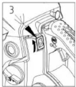
natural_image
Technical diagram of a mechanical assembly with no visible text or symbols
text_image
4
text_image
5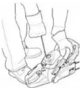
natural_image
Line drawing of two people using a bicycle pedal (no text or symbols)
natural_image
Technical line drawing of a mechanical device with directional arrows indicating motion (no text or symbols)ВКЛЮЧЕНИЕ ДВИГАТЕЛЯ
natural_image
Line drawing of a person's legs and feet wearing a high-heeled shoe (no text or symbols)
ОСТОРОЖНО!
natural_image
Line drawing of a hand using a tool to lift a tree stump (no text or symbols)natural_image
Line drawing of a hand using a tool to adjust or install a mechanical component (no text or symbols visible)natural_image
Illustration of a person using a chainsaw to cut tree bark (no text or symbols)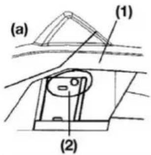
text_image
(a) (1) (2)
text_image
(b) (1) (3)
text_image
(1) (2) (3)
ОСТОРОЖНО!
natural_image
Symbol of a crossed-out saw cutting through pipes, no text or labels presentnatural_image
Illustration of a hand using a tool to cut a circular object with a curved arrow indicating motion (no text or symbols)natural_image
Illustration of a person using a power tool to cut a circular object with a black arrow indicating rotation (no text or symbols)natural_image
Illustration of a hand using a tool to cut a circular object on a cutting board, with an arrow indicating rotation (no text or symbols)Защита от отдачи
natural_image
Illustration of a mechanical component with circular ports and a curved top part (no text or symbols)natural_image
Simple line drawing of a ground surface with a downward arrow indicating a drop or compression (no text or symbols)
ОСТОРОЖНО!
text_image
Diagram illustrating a logging process with arrows indicating direction and a circular object on grass, labeled with symbols like '60' and '10'.text_image
Diagram illustrating a mechanical or physical setup with labeled components and directional arrows, likely from an engineering or physics context.text_image
Diagram illustrating airflow around a circular object with labeled parts ① and ②, showing directional arrows.
text_image
Diagram showing two labeled arrows (① and ②) pointing to a curved structure with an arrow indicating direction.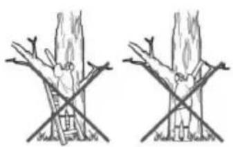
natural_image
Two hand-drawn diagrams showing tree branches with arrows indicating movement or force (no text or symbols)natural_image
Exploded view diagram of a mechanical device showing internal components and housing (no text or labels)
ОСТОРОЖНО!
natural_image
Hand holding a small object with a spiral pattern, being pointed at by a tool (no text or symbols visible)natural_image
Technical line drawing of a mechanical device with gears and levers (no text or symbols)natural_image
Line drawing of a hand holding a tool, with no visible text or symbolsnatural_image
Technical line drawing of a vehicle's internal components (no text or symbols)natural_image
Technical line drawing of a mechanical device with hoses and components (no text or symbols)2. Топливный фильтр
natural_image
Simple line drawing of a person using a tool to cut a tree stump (no text or symbols)
natural_image
Simple line drawing of a mechanical clamp or bracket assembly (no text or symbols)Пильная цепь

ОСТОРОЖНО!
text_image
Technical diagram of a chain-linking device with numbered parts for identificationtext_image
(11) (13)natural_image
Illustration of a hand using a chain-linking tool to lift a tree branch (no text or symbols)natural_image
Illustration of a fuel being poured into a gas cylinder with an oil pump icon (no text or symbols)ПАЛЬНЕ
natural_image
Illustration of a no-smoking cigarette crossed out of a campfire (no text or symbols)
ПОПЕРЕДЖЕННЯ!
text_image
chain oil
text_image
Technical diagram of a tracked vehicle with labeled parts 1 and 2
natural_image
Technical diagram of a mechanical assembly with no visible text or symbols
text_image
4
text_image
5
natural_image
Line drawing of a person's legs and feet wearing a high-visibility cleat (no text or symbols)
natural_image
Technical line drawing of a mechanical device with directional arrows indicating motion (no text or symbols)ЗАПУСК ДВИГУНА
natural_image
Line drawing of a person's legs and feet wearing a high-visibility bench (no text or symbols)
ПОПЕРЕДЖЕННЯ!
natural_image
Line drawing of a hand using a tool to lift a tree stump (no text or symbols)ПЕРЕВІРКА ПОДАЧІ МАСТИЛА
natural_image
Line drawing of a hand using a tool to adjust or install a mechanical component (no text or symbols visible)natural_image
Illustration of a person using a chainsaw to cut tree bark (no text or symbols)
text_image
(a) (1) (2)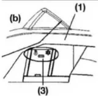
text_image
(b) (1) (3)
text_image
(1) (2) (3)
ПОПЕРЕДЖЕННЯ!
natural_image
Prohibition sign showing a diagonal slash over a pipe, crossed out by a diagonal line (no text or symbols)ПОПЕРЕДЖЕННЯ!
natural_image
Illustration of a hand using a tool to cut a circular object with a curved arrow indicating rotation (no text or symbols)natural_image
Illustration of a person using a power tool to cut a circular object with a curved arrow indicating motion (no text or symbols)natural_image
Illustration of a hand using a tool to cut a ball on a rolling surface, with an arrow indicating motion direction (no text or symbols)natural_image
Pure mechanical component diagram without any text, numbers, or symbolsnatural_image
Simple line drawing of a ground surface with a downward arrow indicating a drop or direction (no text or symbols)text_image
Diagram illustrating a logging or logging process with arrows indicating direction and a circular object on ground.text_image
Diagram illustrating a logging or drilling process with labeled components and directional arrows, likely for surveying or engineering purposes.text_image
Diagram illustrating airflow or heat transfer between two circular objects with labeled arrows and directional arrows
text_image
Diagram showing two labeled arrows pointing to a curved structure with annotations ① and ②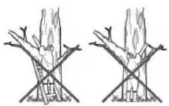
natural_image
Two hand-drawn diagrams showing tree stumps with cross-arms, no text or symbols presentnatural_image
Exploded view diagram of a mechanical device showing internal components and housing (no text or labels)
ПОПЕРЕДЖЕННЯ!
natural_image
Hand holding a small object with a spiral arrow, no visible text or symbolsnatural_image
Technical line drawing of a mechanical device with gears and levers (no text or symbols)2. Подача мастила
natural_image
Illustration of a hand holding a tool with a ruler, showing a pen tip and a labeled part (1) (no text or symbols on the diagram itself)3. Напрямна (шина)
natural_image
Interior view of a car showing engine, air intake manifold, and dashboard (no text or symbols visible)natural_image
Line drawing of a mechanical device with hands operating it (no text or symbols)2. Фільтр пального
natural_image
Simple line drawing of a hand holding a tool next to a rock (no text or symbols)
natural_image
Simple line drawing of a mechanical clamp or bracket assembly (no text or symbols)Пиляльний ланцюг

ПОПЕРЕДЖЕННЯ!
text_image
Technical diagram of a chain-linking device with numbered parts for identificationnatural_image
Illustration of a hand using a chain-linking tool to cut a chain, showing motion arrows (no text or symbols)YAKIT VE ZINCIR YAĞI

natural_image
Illustration of a fuel being poured into a gas cylinder with an oil pump icon (no text or symbols)YAKIT
natural_image
Illustration of a no-smoking cigarette crossed out of a campfire (no text or symbols)
UYARI!
text_image
chain oil
text_image
Technical diagram of a tracked vehicle with labeled parts 1 and 2
text_image
Technical diagram showing mechanical assembly with labeled components and directional arrows
text_image
4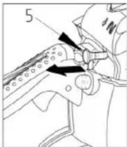
text_image
5
natural_image
Line drawing of a person's legs and feet wearing a high-visibility cleat (no text or symbols)
natural_image
Mechanical device diagram showing a lever mechanism with directional arrows (no text or symbols)MOTORUN DEVREYE ALINMASI
natural_image
Line drawing of a person's legs and feet wearing a footbelt, holding a small object (no text or symbols)
UYARI!
natural_image
Illustration of a hand using a tool to lift a rock with grass (no text or symbols)YAĞ BESLEME KONTROLÜ
natural_image
Line drawing of a hand using a tool to adjust or install a mechanical component (no text or symbols present)text_image
Diagram illustrating a manual logging process with a chainsaw and tree stump, showing gear and tool movement.
UYARI!
text_image
(a) (1) (2)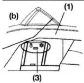
text_image
(b) (1) (3)
text_image
(1) (2) (3)natural_image
Prohibition sign showing a diagonal slash over a pipe, enclosed in a circle (no text or symbols)
UYARI!
natural_image
Illustration of a hand using a saw to cut a circular object with a rotating arrow (no text or symbols)natural_image
Illustration of a hand using a tool to lift a circular object, with an arrow indicating rotation (no text or symbols)natural_image
Illustration of a hand using a tool to cut a circular object, with an arrow indicating rotation (no text or symbols)natural_image
Simple line drawing of a ground surface with a downward arrow indicating a drop or direction (no text or symbols)
UYARI!
text_image
Diagram illustrating a logging or surveying process with labeled arrows and numbered markers indicating steps or zones.text_image
Diagram illustrating a mechanical or physical process with labeled components and directional arrows, likely from an engineering or physics context.text_image
Diagram illustrating airflow around a circular object with labeled parts ① and ②, showing directional arrows.
UYARI!
text_image
Diagram showing two labeled arrows pointing to a curved structure with annotations ① and ②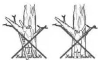
natural_image
Two hand-drawn diagrams showing a person climbing a ladder and standing on a crossbar, with no text or symbols present.Kirpma
natural_image
Exploded view diagram of a mechanical device showing internal components and housing (no text or labels)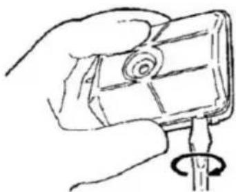
natural_image
Hand holding a small electronic device with a spiral coil (no text or symbols visible)
UYARI!
natural_image
Technical line drawing of a mechanical device with labeled parts (1), showing internal components and no readable text or symbols.2. Yağ bağlantısı
natural_image
Line drawing of a hand holding a tool with a labeled component (1), no text or symbols presentnatural_image
Technical diagram of a vehicle engine bay with internal components and no visible text or symbolsnatural_image
Technical line drawing of a mechanical device with no visible text or symbols2. Yakıt filtresi
natural_image
Simple line drawing of a saw cutting into a tree stump (no text or symbols)
natural_image
Simple line drawing of a mechanical clamp or bracket (no text or symbols)Testere zinciri