PBK 4 B3 - Power Tools PARKSIDE - Free user manual and instructions
Find the device manual for free PBK 4 B3 PARKSIDE in PDF.

| Product type | 4-in-1 modular petrol tool |
| Brand | Parkside |
| Model | PBK 4 B3 |
| Category | Power tools |
| Engine | 2-stroke air-cooled engine, displacement 51.7 cm³, max power 1.45 kW (1.97 hp) |
| Weight (engine unit) | 6.1 kg |
| Weight (pruner pole) | 7.8 kg |
| Weight (hedge trimmer) | 8.5 kg |
| Weight (brush cutter / 3-tooth blade) | 8 kg |
| Fuel tank capacity | 1200 ml |
| Fuel mixture | Unleaded petrol 90+ and 2-stroke oil, ratio 40:1 |
| Chain oil tank capacity | 120 ml |
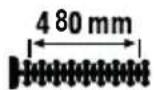
| Hedge trimmer cutting length | 480 mm |
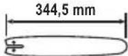
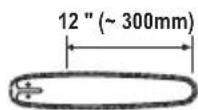
| Pruner pole guide bar length | 344.5 mm (12") |
| Chain speed | 20 m/s |
| Spool cutting radius | 43 cm |
| 3-tooth blade cutting radius | 25.5 cm |
| Guaranteed sound power level | 114 dB |
| Warranty | 3 years |
| Spare parts | Available at www.grizzlytools.shop |
| Maintenance | Clean after each use, regular chain lubrication, replace air filter and spark plug |
| Safety | Wear PPE (goggles, gloves, helmet, hearing protection, shoes), use shoulder strap, safety distance 15 m, do not use in rain |
Frequently Asked Questions - PBK 4 B3 PARKSIDE
User questions about PBK 4 B3 PARKSIDE
0 question about this device. Answer the ones you know or ask your own.
Ask a new question about this device
Download the instructions for your Power Tools in PDF format for free! Find your manual PBK 4 B3 - PARKSIDE and take your electronic device back in hand. On this page are published all the documents necessary for the use of your device. PBK 4 B3 by PARKSIDE.
USER MANUAL PBK 4 B3 PARKSIDE
natural_image
Product photo of a manual tool set including a shov, blade, and gear (no text or symbols visible)
text_image
PDF ONLINE www.lidl-service.comBenzin-Kombigerät 4-in-1 / 4-in-1 Petrol Multi Tool / Outil modulable à essence 4 en 1 PBK 4 B3
DE AT CH
4-in-1 Petrol Multi Tool
Translation of the original instructions
Read carefully before use and keep in a safe place for future reference.
NL BE
Benzine-combiapparaat 4-in-1
Before reading, unfold the page containing the illustrations and familiarise yourself with all functions of the device.
FR BE
GB / MT Translation of the original instructions Page
text_image
Diagram showing a mechanical or electrical component with labeled points A and B, and directional arrows indicating motion or force.natural_image
Pure mechanical component diagram without any text, numbers, or symbolsnatural_image
Diagram showing a mechanical joint or pipe with an arrow indicating force or direction (no text or symbols present)natural_image
Diagram showing three rectangular blocks with downward arrows indicating flow or movement (no text or symbols)natural_image
Diagram showing a tool interacting with a textured surface, no text or symbols presentGeneral description......39
Scope of delivery....39
Overview....40
Description of functions......41
Technical data......41
Safety information......42
Symbols used in the instruction manual 42
Symbols on the device 42
General safety instructions......44
Residual risks....44
Safety instructions for portable engine-driven hedge trimmers....44
Safety information for pruners......46
Kickback causes and how to avoid them with pruners....47
Safety instructions for string trimmers and grass trimmers....47
String trimmer - kickback causes and how to avoid them with a 3-tooth blade ....48
Assembly....48
Fitting the middle tubular shaft .....49
Fitting the tubular shaft....49
Fitting the round handle 49
Fitting the protective cover......50
Removing/attaching the extension of the protective cover ....50
Fitting the saw chain....50
Assembling the 3-tooth blade......51
Assembling the spool....51
Initial start-up....51
Filling with fuel 51
Tensioning the saw chain 52
Chain lubrication ....53
Swivelling out the cutter bar .....53
Putting the shoulder strap on....54
Sliding the carrying eye....54
Extending the line 55
Switching on and off 55
Safe working....56
Working with the hedge trimmer......56
Working with the pruner .....57
Working using the spool....57
Working with the 3-tooth blade......57
Putting down the device....58
Cutting techniques using the hedge trimmer....58
Cutting techniques using the pruner...58
Cleaning and servicing......59
Cleaning....60
Service intervals....60
Sharpening the cutting teeth .....60
Changing the saw chain....61
Maintaining/turning the blade bar....61
Replacing the spool....61
Winding up the spool....62
Replacing/adjusting the spark plug...62
Sharpening the line cutter 62
Cleaning/replacing the air filter......63
Replacing the fuel filter 63
Lubricating the gears 63
Adjusting the carburettor 63
Storage......63
Transport......64
Disposal/environmental protection 64
Guarantee 65
Repair Service......66
Service-Center......66
Importer 66
Spare parts/accessories ......66
Troubleshooting 67
Translation of the original EC Declaration of Conformity ..... 362
Exploded view......373
Introduction
Congratulations on purchasing your new device. You have chosen a high-quality product. This device was quality-tested and subjected to a final inspection during production, This ensures proper functioning of your device. In some cases, residual amounts of lubricants may be present on or in the device. This is not a flaw or a defect and is no cause for concern.

The instruction manual forms part of this product. It contains important information on safety, use and disposal. Before using the product, you should familiarise yourself with all operating and safety instructions. Use the product only as described and for the stated fields of application. Store the instruction manual carefully and ensure that all documents are handed over in the event that the product is passed on to another user.
Proper use
With the hedge trimmer attachment, this device is intended for cutting and trimming hedges, bushes and ornamental shrubs. The pole-mounted pruner attachment is intended for trimming large branches and limbs. The trimmer and 3-tooth blade attachment is intended for cutting grass in the garden, along flower beds, around trees or fence posts, and light under-growth. The device is intended for use in residential applications.
The device is not intended for commercial use. The warranty is void in the case of commercial use. Any other use that is not expressly permitted in this instruction manual may result in damage to the device and pose a serious hazard to the user.
The device is intended for use by adults. Children under the age of 16 may not use the device, except under supervision. Local regulations may specify an age limit for the user. The use of the device in the rain or a damp environment is prohibited.
The operator or user is responsible for any accidents or personal injury and/or material damage to third parties or their property. The manufacturer is not liable for damage caused by improper use or incorrect operation.
General description

An illustration of the most important functional components can be found on the front and the back fold-out pages.
Scope of delivery
- Engine unit
- Hedge trimmer attachment
- Pole-mounted pruner attachment
- Trimmer attachment
- Extension attachment, length: 905 mm
- Saw chain
- Blade bar
- Spool cap
- Round handle
- 3-tooth blade
- Protective cover
- 100 ml organic saw chain oil
- 1 x mixing container
- Funnel
- 1 x shoulder strap
- 1 x hex key
- 1 x spark plug wrench with slotted screwdriver
- Tool bag
- 3 x Transport protection
- Protective goggles
- Spare line (2.4 mm x 6 m)
- Instruction manual
GB MT

Hex keys, spark plug spanner with slotted screwdriver and spare line are in the tool bag (34) when delivered.
Overview
A
1 Blade bar
2 Front tubular shaft
3 Butterfly screw
4 Middle tubular shaft
5 Tubular shaft
6 Carrying eye
7 Throttle lever 8 Handle
9 Round handle 10 Button
11 Transport protection
12 Protective grip
13 Transport protection 14 Handle
15 3-tooth blade
16 Transport protection
17 Spool cap
18 Line cutter 19 Extension 20 Pusher
21 Protective cover
22 Hexagon socket screw
23 Protective cap
24 Fuel mixing bottle 25 Bottle
26 Mounting key/ Spark plug wrench 27 Screwdriver
28 Hex key
29 Shoulder strap
30 Quick release lock
31 Body protection
32 Protective goggles 33 Funnel
34 Tool bag
35 STOP switch
36 Throttle lock
B
37 Borehole
38 Butterfly screw
39 Flap
40 Rubber
41 Pin
E
42 Chain sprocket
43 Coach screw
44 Saw chain
45 Oil passage
46 Screw
47 Lug
48 Nut
49 Sprocket cover
F
50 Uptake spindle
51 Nut
52 Clamping disk
53 Washer
H
54 Fuel tank
55 Tank cover
1
56 Oil tank cap
57 Oil tank
58 Minimum mark
59 Adjusting screw
1
60 Locking lever
61 Safety lever
L
62 Screw
M
63 Starter handle
64 Choke lever
65 Fuel pump (primer)
N
66 Line outlet loop
67 Recesses
68 Click lock
69 Spool
70 Groove
71 Notch
72 Spark plug 73 Spark plug connector
P 74 Screw
75 Air filter cover
76 Air filter
77 Air filter housing
Q 78 Fuel filter
R 79 Screw
Description of functions
The device is powered by an air-cooled 2-stroke engine. The device is equipped with a hedge trimmer attachment with safety cutter bar, a pruner attachment with saw chain and a trimmer attachment with spool or 3-tooth blade.
Please refer to the descriptions below for information on how the operating elements work.
Technical data
Petrol Multi Tool....PBK 4 B3
Engine......2-stroke engine, air-cooled
Fuel mixture....40:1
Engine displacement V....51.7 cm ^3
Engine power P _max ......1.45 kW (1.97 PS)
Engine no-load rotation speed ...3000 rpm
Engine speed....9500 rpm
Tank capacity/
tank volume......1200 ml/1200 cm ^3
Weight (engine unit)....6.1 kg
Guaranteed sound power level (LWA) 114 dB
Engine manufacturer Trade name......WUYANG
Name of the
company......Zhejiang Wu Yang
Industry & Trade Co., Ltd.
Contact address
in the Union .... Rake Forester GmbH, ....Andre-Citroen-Str. 18, ....D51149 Cologne, Germany
PBK 4 B3-4 - Pruner
Weight....≈7.8 kg
Blade bar.....KangxinAL12-44-507P(12") Blade bar length ..... 344.5 mm Cutting length ....approx. 12"(\~300 mm) Sprocket teeth ..... 7
Chain....Kangxin 3/8.050x44DL Chain thickness....1.3 mm Chain speed v _0 ....20 m/s
Oil tank volume ....120 cm ^3 /120 ml Vibration (q _h ) at handle idle ....7.237 m/s ^2 ; K= 1.5 m/s ^2 in operation ...7.420 m/s ^2 ; K= 1.5 m/s ^2
Vibration ( q_h ) at round handle idle ....7.511 m/s ^2 ; K= 1.5 m/s ^2 in operation ...7.723 m/s ^2 ; K= 1.5 m/s ^2
Emission sound pressure level at the operator's location (L_pA) .....99.0 dB; K_pA = 1.98 dB Measured sound power level (L_WA) .....108.8 dB; K_WA = 3 dB
PBK 4 B3-3 - Hedge trimmer
Weight ....≈8.5 kg Cutting length .... 480 mm Max. recommended
branch thickness 11 mm
No-load rotation speed n_0 .....1550 rpm Cuts per minute.....3100
Vibration ( q_h ) at handle ....8.37 m/s ^2 ; K=1.5 m/s ^2 at round handle .6.15 m/s ^2 ; K=1.5 m/s ^2
Sound pressure level ( L_pA )...98.8 dB; K_pA=3 dB Measured sound power level ( L_WA ).....109.7 dB; K_WA=1.98 dB
PBK 4 B3-2 - Trimmer, spool
Weight....≈8 kg Cutting circle, spool.....43 cm / 430 mm Line thickness.....2.4 mm Line length.....6.0 m
Rotational speed n_0 .....7800 rpm
GB MT
Vibration ( a_h ) at handle ....7.39 m/s ^2 ; K=1.5 m/s ^2 at round handle .7.99 m/s ^2 ; K=1.5 m/s ^2 Sound pressure level
(L_pA) 99.5 dB; K_pA = 3 dB Measured sound power level
(L_WA) .....110.1 dB; K_WA = 1.98 dB
PBK 4 B3-2 - String trimmer, 3-tooth blade
Weight ≈8 kg
Cutting circle .... 25.5 cm/255 mm Rotational speed n _0 ....7800 rpm
Rotational speed of 3-tooth blade n ....10000 rpm Vibration (a _b )
at handle ....8.49 m/s ^2 ; K= 1.5 m/s ^2 at round handle .6.20 m/s ^2 ; K= 1.5 m/s ^2 Emission sound pressure level at the operator's location (L pA ) ..98.9 dB; K pA = 3 dB Measured sound power level
(L_WA) .....109.6 dB; K_WA = 1.98 dB
The vibration emission value has been measured according to a standardised testing method and may be used for comparison with another power tool.
The indicated vibration emission value may also be used for an introductory assessment of the exposure.
Levels of noise and vibration were determined according to the standards and regulations in the declaration of conformity.
Warning: The vibration emission value whilst actually using the power tool may vary from the given values depending on the type and way in which the power tool is used.
Try to keep the exposure to vibrations as low as possible. Examples of measures to reduce vibration exposure are the wearing of gloves when using the tool and limiting the working hours. All parts of the operating cycle have to be considered while doing so (for example, times when the power tool is switched off and times when it is switched on but running without any load).
The carbon dioxide (CO2) emission value determined by an EU type-approval procedure for this device is: 1063.00 g/kWh
Safety information
This section describes the basic safety rules when working with the device.
Symbols used in the instruction manual

Hazard symbol with information on the prevention of personal injury or property damage

Hazard symbol with information on damage prevention

Advisory symbol with information on how to best use the device
Symbols on the device

Caution!

Read the instruction manual and follow all warnings and safety instructions.

Wear eye protection!

Wear hearing protection!

Wear a safety helmet!

Wear safety gloves.

Wear cut-resistant work clothing.

Wear non-slip safety shoes.

Do not leave long hair uncovered. Keep hair away from moving parts.

Do not expose the device to rain. The device must not be operated damp nor in a damp environment.

Caution! Risk of injury from moving blades

Caution! Falling objects, especially when cutting above head height

Disconnect the spark plug connector before maintenance work.
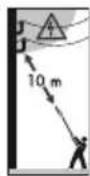
Danger to life from electrical shock! Stay at least 10m away from over-head power lines.

Danger due to ejected parts! Keep other people away.

Keep persons in the vicinity away from the device

Caution! Kickback - be aware that you may experience kickback while working with the machine.

Danger due to ejected parts! Keep other people away.


Caution! Hot surface There is a risk of burns.

Keep a safe distance of at least 15 m from other people.

Guaranteed sound power level L_WA indicated in dB
Cutting length
Blade bar length
Cutting length

Cutting circle (spool)

Cutting circle (3-tooth blade)

Mixing ratio 40:1, ONLY use fuel mixture
Open fl ames, fi re, open ignition sources and smoking are prohibited.

+Δ Tank cover for fuel mixture


Do not use any circular- or multi-toothed saw blades. Risk of injury!

Start-up Sequence

Choke: Cold start

Choke: Warm start

Chain lubrication direction of rotation, screw
Direction of travel, saw chain

For use with the spool
GB MT

For use with the 3-tooth blade

Direction of travel, spool

Reference to screw for lubrication with a grease gun

General safety instructions

Do not work with the device without having received the necessary train-how to use it.

Before working with the device, familiarise yourself with all the controls. Practise handling the device and have the functionality, mode of action and working techniques explained to you by an experienced user or an expert. Make sure that you are able to switch off the device immediately in case of an emergency. Improper use of the device can cause severe injury.
If an accident or malfunction occurs during operation, switch off the device immediately. Injuries must be properly treated or medical assistance sought. Read the "Troubleshooting" section to correct any malfunctions or contact our Service Centre.

Residual risks
There will always be residual risks even if you operate this power tool according to the instructions. The following hazards may occur in connection with the type and design of this power tool:
a) Cutting injuries
b) Hearing damage if suitable ear protection is not worn.
c) Health injuries resulting from the effect of hand/arm vibration in the event that the device is used over a longer period of time or is not used and maintained properly.
Safety instructions for portable engine-driven hedge trimmers
Familiarise yourself with the instruction manual before attempting to operate the device.
IMPORTANT READ CAREFULLY BEFORE USE KEEP IN YOUR FILES
Preparation
a) THIS HEDGE TRIMMER CAN CAUSE SERIOUS INJURIES! Read the instructions carefully regarding the correct handling, preparation and maintenance, for starting and stopping the hedge trimmer. Familiarise yourself with all of the controls and the proper use of the hedge trimmer.
b) Children must never be allowed to use the hedge trimmer.
c) Caution! Notice overhead power lines.
d) Use of the hedge trimmer should be avoided when people, especially children, are nearby.
e) Wear suitable clothing! Do not wear loose clothing or jewellery that can become jammed in the moving parts. It is recommended that you wear solid gloves, non-slip shoes and protective goggles.
f) Handle fuel with special care, it is highly flammable and the vapours are explosive. The following points should be observed.
1) Only use a container specifically designed for this purpose.
2) Never remove the fuel cap or add fuel when the engine is running. Let the engine and exhaust components cool down before fuelling.
3) No smoking.
4) Refuel outdoors only.
5) Never store the hedge trimmer or fuel container in a room where there is an open flame, e.g. near a water heater.
6) If fuel has spilled, do not attempt to start the engine, but set the hedge trimmer away from the petrol-contaminated surface before starting.
7) Always put the tank lid back on and lock it safely after filling.
8) When emptying the fuel tank, make sure to do this outdoors.
g) If the cutting mechanism comes in contact with a foreign body or if the operating noises increase or the hedge trimmer vibrates with unusually high force, switch off the engine and let the hedge trimmer come to a standstill. Pull the spark plug connectors from the spark plug and take the following measures:
1) check for damages;
2) check for loose parts and fasten all loose parts;
3) replace damaged parts with equivalent parts or have them repaired.
h) Wear hearing protection while using the device.
i) Wear eye protection while using the device.
j) If an accident or malfunction occurs during operation, switch off the device immediately. Injuries must be properly treated or medical assistance sought.
Operation
a) The engine must be stopped before:
1) cleaning or removing a blockage;
2) inspection, servicing or work on hedge trimmer;
3) adjusting the working position of the cutting unit;
4) leaving the hedge trimmer unattended.
b) Always ensure that the hedge trimmer is properly placed in one of the indicated working positions before the engine is started.
c) While operating the hedge trimmer, always ensure that you have a secure footing, particularly if steps or a ladder is being used.
d) Do not use the hedge trimmer with a defective or strongly worn-out cutting unit.
e) To avoid risk of fire, pay attention that the engine and sound absorber are free from deposits, leaves or excess lubricant.
f) Always ensure that all handles and safety equipment are in place when using the hedge trimmer. Never try to use an incompletely assembled hedge trimmer or a hedge trimmer with impermissible modifications.
g) Always use both hands when operating the hedge trimmer.
h) Always be aware of your surroundings and stay alert for possible hazards that you may not hear because of the noise of the hedge trimmer.
Maintenance and storage
a) When the hedge trimmer is stopped for maintenance, inspection or storage, switch off the engine, make sure that all rotating parts have stopped and remove the spark plug connector from the spark plug. Allow the hedge trimmer to
GB MT
cool down before checking, adjusting, etc.
b) Store the hedge trimmer in a place where fuel vapours cannot come into contact with open flames or sparks. Always let the hedge trimmer cool down before you put it into storage.
c) When transporting or storing the hedge trimmer, always attach the transport protection to the cutting attachment.
Additional information
- Use the shoulder strap and hold the machine by the handle and round handle. Take breaks and change your working position regularly.
- Always ensure good ventilation when handling fuel. Do not smoke while refuelling and keep any heat sources at a distance. Never refuel while the engine is running.
- Before removing blockages, switch off the engine and let the device cool down.
Safety information for pruners

National regulations may limit the use of the machine.
- Inspect the machine daily before each use and after dropping or other impacts to check for significant damage or defects.
- Do not use the machine near overhead power lines. Otherwise there is a risk of electric shock!
- Wear personal protective equipment when using the machine: Hearing protection, eye protection (visor or goggles), head protection and cut-proof, tight-fitting work clothes.
- Wear non-slip foot protection when using the machine.
• Duration of use and breaks
Prolonged use of the machine can lead to problems with the blood circulation in the hands caused by vibrations, known as white finger disease. You can however extend your potential machine use time by wearing appropriate gloves or by taking regular breaks. Please ensure that if you are susceptible to poor circulation, low outside temperatures or strong gripping forces while working, this may reduce the length of time for which you are able to work.
• Always remain attentive. Pay attention to what you are doing.
Use common sense. Do not use machines if you are tired. You may not operate the machine under the influence of alcohol, medication or drugs that impair your ability to react.
- Use the shoulder strap and hold the machine by the handle and round handle. Take breaks and change your working position regularly.
- Keep a safe distance from other persons and hold the machine only by the specified grip surfaces.
- When cutting overhead, take care not to be hit by falling branches.
- Do not assume a dangerous working position. Never work on a ladder! Only work on firm and stable surfaces! Avoid an abnormal body posture. Keep your balance at all times. Ensure that there is sufficient lighting during the work. Make sure you have a secure footing in wet conditions, snow, ice, on slopes and on uneven terrain.
- Warning of exhaust emissions
The machine produces toxic exhaust gases as soon as the engine is running. These gases can be odourless and
invisible. Therefore, never work with the machine in closed or poorly ventilated rooms.
Kickback causes and how to avoid them with pruners

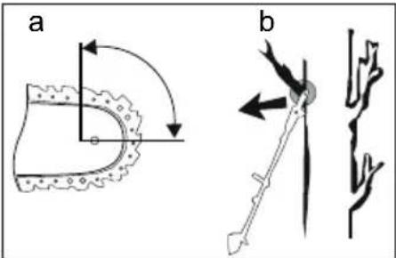
Caution - kickbacks! Be aware that you may experience kickback while working with the device. There is a risk of injury. Kickbacks can be avoided through taking the appropriate care and using the correct sawing technique.
text_image
a b- Kickbacks may occur if the tip of the guide rail touches an object, or if the wood bends and the saw chain gets caught in the cut (see Fig. b).
- Under some circumstances, contact with tip of the rails can lead to an unexpected backwards reaction movement during which the guide rails move upwards and strike the operator (see Fig. a).
- If the saw chain becomes stuck along the top edge of the guide rail, the rail can kick back heavily towards to the operator.
- Each of these reactions can lead to you losing control of the saw and potentially being seriously injured. Do not rely exclusively on the safety devices built into the chainsaw. As user of the chainsaw, you should undertake various measures to enable accident- and injury-free working.
A kickback is caused by wrongly or incorrectly operating the power tool. It can be avoided by suitable cautionary measures, such as described below:
- Hold the saw firmly with both hands with thumbs and fingers surrounding the chainsaw handles. Place your body and arms in a position where you can withstand the kickback forces.
The operator will be capable of with- standing the kickback forces if suitable measures are undertaken. Never let go of the chainsaw. - Avoid an abnormal body posture. This enables better control over the chainsaw in unforeseen situations.
• Always use the replacement rails and saw chains specified by the manufacturer. Incorrect replacement rails and saw chains can cause the chain to break apart and/or may lead to kickback. - Comply with the manufacturer's instructions for sharpening and maintaining the saw chain. Depth gauges placed too low increase the potential for kickbacks.
- Do not saw with the tip of the blade bar (see Fig. b). There is a risk of kickback.
- Ensure there are no objects on the ground which could cause you to stumble.
Safety instructions for string trimmers and grass trimmers
- Inspect the machine daily before each use and after dropping or other impacts to check for significant damage or defects.
GB MT
- Wear personal protective equipment when using the machine: Hearing protection, eye protection (visor or goggles), head protection and cut-proof work clothes.
- Wear non-slip foot protection when using the machine.
- Use the shoulder strap and hold the machine by the handle and round handle.
• Always remain attentive. Pay attention to what you are doing.
Use common sense. Do not use machines if you are tired. You may not operate the machine under the influence of alcohol, medication or drugs that impair your ability to react.
- Before removing blockages, switch off the engine and let the device cool down.
- Keep a safe distance of at least 15 metres from other persons and hold the machine only by the specified grip surfaces.
• Warning of exhaust emissions
The machine produces toxic exhaust gases as soon as the engine is running. These gases can be odourless and invisible. Therefore, never work with the machine in closed or poorly ventilated rooms.
• Duration of use and breaks
Prolonged use of the machine can lead to problems with the blood circulation in the hands caused by vibrations, known as white finger disease. You can however extend your potential machine use time by wearing appropriate gloves or by taking regular breaks. Please ensure that if you are susceptible to poor circulation, low outside temperatures or strong gripping forces while working, this may reduce the length of time for which you are able to work.
- Do not assume a dangerous working position. Never work on a ladder! Only work on firm and stable surfaces! Avoid an abnormal body posture. Keep your balance at all times. Ensure that there is sufficient lighting during the work. Make sure you have a secure footing in wet conditions, snow, ice, on slopes and on uneven terrain.
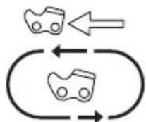
String trimmer - kickback causes and how to avoid them with a 3-tooth blade

In the event of a kickback, the operator will feel a powerful blow from the combination machine. This may lead to losing control of the device and serious injury. You can avoid kickbacks through caution and proper technique.
While working with the 3- tooth blade there is a risk of kickback if the blade edge hits an obstacle (stone, wood).
- Hold the device with both hands.
- Make sure there are no obstacles on the ground and do not use the 3-tooth blade near fences, metal posts or similar.
text_image
Diagram showing a mechanical or electrical component with labeled points A and directional arrows indicating motion or force.Use only properly sharpened tools. To cut thick stems, switch the device to position A.
Assembly

Disconnect the spark plug connector (☐ 73) before carrying out any work on the e.

Only use original parts.

The device can be used with either the hedge trimmer, pruner or trimmer attachment, either with the spool or the 3-tooth blade.

Removal is carried out in reverse order.

Fitting the middle tubular shaft

The middle tubular shaft is for use with the pruner attachment and hedge trimmer attachment.
- Loosen the butterfly screw (3).
- Slide the middle tubular shaft (4) into the tubular shaft (5) on the device housing. For a detailed view of the procedure, take a look at Fig. S.
- Turn the middle tubular shaft (4) with a gentle rotating movement until the button (10) clicks into place in the hole in the tubular shaft (5).
- Fix the middle tubular shaft (4) in place with the butterfly screw (3).

Tighten the butterfly screw
(3) until no more play is discernible on the middle tubular shaft (4)! The use of maximum manual force will damage the tubular shaft.

Fitting the tubular shaft

If necessary, remove the protective cap(s) (23) from the front tubular shaft (2) before assembly.

The front tubular shaft of the pruner and the hedge trimmer attachment
is mounted on the middle tubular shaft (4).
- Loosen the butterfly screw (3).
- Push the front tubular shaft (2) into the tubular shaft (5) on the device housing or into the middle tubular shaft (4). For a detailed view of the procedure, take a look at Fig. S.
- Turn the front tubular shaft (2) with a slight twisting motion until the button (10) engages in the hole in the tubular shaft (5) or in the middle tubular shaft (4).
- Fix the front tubular shaft (2) in place with the butterfly screw (3).

Tighten the butterfly screw (3) until no more play is dis cernible on the front tubular shaft (2)! The use of maximum manual force will damage the tubular shaft.

Fitting the round handle

For safety reasons, the round handle (9) may only be fixed of the two positions given the hole.

The leg protection must always be mounted on the operator side!
- If necessary, loosen the butterfly screw (38) and put the silver-coloured flap (39) upright.
- Place the round handle (9) on the rubber (40) on the tubular shaft (5) from above. Select one of the two positions given by the hole (37) in the tubular shaft (5). You can slide the rubber (40) to the desired position.
GB MT
The pin (41) in the round handle (9) must be seated in the hole of the rubber (40), otherwise the round handle (9) cannot be fitted correctly.
- Close the flap (39) and secure it with the butterfly screw (38).
C Fitting the protective cover
The protective cover (21) must be fitted on the front tubular shaft (2) with the retainer for spool and 3-tooth blade.
- Place the protective cover (21) on the holder on the front tubular shaft (2).
- Screw the protective cover (21) to the front tubular shaft (2) with the four hexagon socket screws (22).
D Removing/attaching the extension of the protective cover
When using the 3-tooth blade, the extension (19) of the protective cover (21) must be removed.
When using the spool, the extension (19) must be fitted.
Removing the extension of the protective cover
- Unclip the three pushers (20) of the click lock using the screwdriver (A 27).
- Pull off the extension (19) of the protective cover (21).
Fitting the extension of the protective cover
- Clip in the three pushers (20) of the click lock using the screwdriver (27).
Clean the extension (19) and protective cover (21) after each use.
E Fitting the saw chain
Pay attention to the correct rotation direction of the saw chain. This is indicated on the sprocket cover (49) and above the coach screw (43).
Tension the saw chain in accordance with the first 5-6 steps. see section "Tensioning the saw chain".
- Place the device on a level surface.
- Remove the chain wheel cover (49) by loosening the nut (48) with the mounting key (26).
- Place the saw chain (44) into the blade groove. Place the saw chain (44) into the chain sprocket (42).
- Place the blade bar (1) and saw chain (44) on the coach screw (43). When the nose (47) on the right below the coach screw (43) sits in the lower round recess on the blade bar, the blade bar is placed correctly.
i It is normal for the saw chain (44) to sag. - Pretension the saw chain (44) by turning the screw (46) in a clockwise direction with the screwdriver (27).
- Put the chain wheel cover (49) back in position. Tighten the nut (48) of the sprocket cover.
Caution! The saw chain (44) can be re-oiled.

Assembling the 3-tooth blade

Safe use of the device can only be guaranteed with a PARKSIDE 3-tooth blade. The use of unauthorised knives may cause in-jury.

When using the 3-tooth blade, remove the extension (D 19) of the protective cover, see chapter: "Removing/attaching the extension of the protective cover".
- Place the device on the ground in a stable position.
- Block the uptake spindle (50) using the hex key (28) as depicted.
- Place the 3-tooth blade (15) onto the uptake spindle (50). The blade can be used on both sides.
- Fix the blade, the thinner washer (53), clamping disk (52) and nut (51) anti-clockwise using the mounting key (26).
Insert the nut (51) into the clamping disk (52).

- Remove the hex key (28)!

Removal is carried out in reverse order.

Assembling the spool

When using the spool, fit the extension (19) of the protective cover, see chapter: "Removing/ attaching the extension of the pro- tective cover".

Do not replace the non-metallic filaments of the spool end with metallic filaments! Risk of in- jury!
- Place the device on the ground in a stable position.
- Block the uptake spindle (50) using the hex key (28) as depicted.
- Screw the spool cap (17) anticlockwise back onto the uptake spindle (50).
- Remove the hex key (28)!

Removal is carried out in reverse order.
Initial start-up

Disconnect the spark plug connector (O 73) before carrying out any adjustment on the device.

When working with the device, wear suitable clothing, work gloves, eye protection, protective headgear, hearing protection and cut-resistant work boots. Prior to each use, ensure that the machine is working correctly. Do not lock the On/Off switch in place. Do not use the device if a switch is damaged.
Risk of injury and damage to property.

Observe noise protection rules and other local regulations. Operating the device can be limited or prohibited on certain days (e.g. Sundays and public holidays), certain daytimes (e.g. noon, night rest) or in special areas (e.g. health resorts, hospitals etc.).

Filling with fuel

Always ensure good ventilation when handling fuel. Do not smoke while refuelling
and keep any heat sources at a distance. Never refuel while the engine is running.
Carefully open the fuel filler cap so that any overpressure can slowly dissipate.
Start the device at a distance of at least 3 m from the fuelling point. There is a risk of fire or explosion if this advice is not heeded.

The filling volume of the tank is 1200 ml.

Use only the fuel mixture recommended in the instructions. The fuel mixture ages. Therefore, do not use fuel mixtures that are older than 3 months. If this not done, the engine may become damaged and your warranty will become null and void.

Avoid direct skin contact with petrol and inhalation of petrol. There is a danger to health!

The device is equipped with a two-stroke engine and is
therefore operated exclusively with a mixture of petrol and two-stroke engine oil at a ratio of 40:1.
Fuel mixture table:
| Petrol 2-stroke oil | |
| 1.00 litre 25 ml | |
| 3.00 litres 75 ml | |
| 5.00 litres 125 ml | |
| Mixing process | 40 parts petrol + 1 part oil |
- Use quality unleaded petrol with an octane rating of at least 90.
- For optimal performance, use oil for air-cooled two-strokeengines.
-
Mix petrol and oil in the fuel mixing bottle (24). Use the scale on the container.
-
↓OIL First pour petrol into the fuel mixing bottle (24) up to the line marked "PETROL".
Then add oil until the "OIL" mark is reached.
Close and shake the fuel mixing bottle (24).
- Unscrew the tank cap (55) and fill the fuel mixture into the fuel tank (54) using the funnel (33). Wipe fuel residues off the tank cap (55) and close the tank cap (55) again.

Clean the funnel (33) after use.
Tensioning the saw chain
Do not re-tension or change the saw chain when it is hot because it shrinks slightly once it has cooled down. If this is not observed it can lead to damage on the guide rail or the engine because the saw chain is now too taut on the blade bar.
Regularly tightening the saw chain provides safety for the user and reduces and/or prevents wear and chain damage.
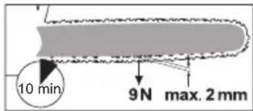
Before starting work and at intervals of approx. 10 minute, we recommend the user to examine the chain tension and correct it if necessary.
The saw chain warms up when working with the saw and thus expands slightly.
These “expansions” can be expected especially from newer saw chains.
Chain tension and chain lubrication have a significant impact on the service life of the saw chain.
The saw chain is properly tensioned when it does not hang from the underside of the blade bar and cannot be moved around by a gloved hand. When pulling on the saw chain with 9 N (approx. 1 kg) of force, the saw chain and blade bar should not be separated by a distance of more than 2 mm.
text_image
10 min 9 N max. 2 mm
Risk of injury! Tension the saw chain with the engine switched off (after).

Tensioning the saw chain
- Loosen the nut (48) of the sprocket cover (49) with the mounting key (26).
- Tension the saw chain (44) by turning the screw (46) in a clockwise direction with the screwdriver (27).
Reduce the saw chain tension by turning the screw anti-clockwise. - Fix the sprocket cover (49) by tightening the nut (48) with the mounting key (26).

The chain tension of a new saw chain must be readjusted after a maximum of 5 cuts.

Chain lubrication

The blade bar and saw chain must never be operated without oil. If the pruner is used with too little oil, the cutting performance and lifespan of the saw chain will decrease as the saw chain will
become blunt more quickly. You can identify when there is too little oil if smoke develops or the blade bar changes colour.
The oil flows to the blade bar as soon as the engine starts operating.

Always turn off the device and let the engine cool down
before filling with chain oil. Overflowing oil can cause a fire.
Filling with chain oil:
- Check the oil level indicator on the oil tank (57) regularly and top-up the oil if the minimum mark (58) "MIN" is reached on the oil level indicator. The oil tank holds about 120 ml of oil.
- Use bio-oil containing additives to reduce friction and wear. You can order this from our service centre. Alternatively, use chain lubricating oil with a low proportion of adhesion additives.
-
Empty the oil tank if it will not be used for a prolonged period of time (6 - 8 weeks).
-
Unscrew the oil tank cap (56) and pour the chain oil from the bottle (25) into the tank.
-
Wipe off any spilled oil and close the oil tank cap (56) again.

You can regulate the oil inflow via the adjusting screw (59) on
the underside of the oil tank.

Swivelling out the cutter bar

The cutter bar must be checked regularly for wear and reground. A blunt cutter bar causes the device to overload. Any damage that results is not covered by the warranty.
GB MT
- Hold the cutter bar by the handle (14) to adjust the cutter bar.
- Unlock the safety lever (61) and keep it pressed.
- By pressing the locking lever (60) at the same time, you release the fixation of the cutter bar.
- Now you can swing out the cutter bar. Use the ratchet steps and allow the locking lever (60) to click back into place.
The device has 12 possible working positions. - Then, release the safety lever (61) again and ensure that it latches back into its initial position.


Putting the shoulder strap on

The body protection (31) on the shoulder strap must be placed between the body and the device.

Generally, we recommend using the shoulder strap whenever using the device.

Always turn the device off before taking off the shoulder strap. Accident hazard!
natural_image
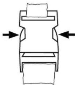
Pure mechanical component diagram without any text, numbers, or symbolsThe shoulder strap is equipped with a quick release device so that the device can be released quickly from the shoulder strap in a danger-
ous situation. In a hazardous situation, press on either side of the quick release de-
vice (see → ←) to clear the quick release device.
- Wear the shoulder strap (29) like a backpack. The clip must be situated on the chest.
- Adjust the strap length so that the body protection (31) is level with the hip.
Place the body protection (31) on your hip between your body and the device. - Open the quick-release lock (30).
- Push on the snap hook and attach the snap hook to the carrying eye (6) on the tubular shaft (5) of the device.
- Clip the quick release lock (30) together with the device back onto the shoulder strap (29).


When wearing the shoulder strap (29), make sure you place the pads on your shoulders for greater comfort.

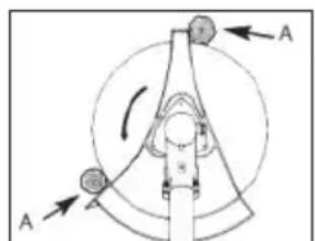
Sliding the carrying eye
Select the appropriate position for the carrying eye (6) for spool/3-tooth blade and pruner/hedge trimmer respectively. You can slide the carrying eye (6) to better distribute the weight of the device.
For spool/3-tooth blade operation:
Without touching it by hand, the device attached to the shoulder strap should be as follows,
① allow the spool to rest lightly on the ground.
② The 3-tooth blade should be balanced around 20 cm above the ground.
-
Loosen the screw (62) on the carrying eye for the shoulder strap using the hex key (28) and tighten it only slightly.
-
Depending on the cutting tool, balance the device according to the above criteria by moving the carrying eye (6) on the tubular shaft (5).
- Tighten the screw (62) when the device is in the desired position.

Extending the line
Your device is equipped with a dual line auto-tap feature, i.e. the two strings are extended when you tap the cutting head on the ground.
- Hold the device in operation over a grassy area.
- Tap the cutting head lightly on the ground a few times. This causes the line to lengthen.

The line cutter (19) inserted in the extension (18) of the protec-
tive cover cuts the line to the desired length.
If the line ends cannot be lengthened:
• Turn off the device.
- Press the spool insert as far as it will go and pull firmly on the end of the string.
If no line ends are visible:
- Replace the spool (see chapter on 'Replacing the spool').

Caution! Thread remnants can be projected and lead to es.

Switching on and off

Start the engine at least 3 meters from where you refu-elled.
The saw chain must not move when idle. If the saw chain moves when the engine is idle, there is a problem with the clutch or no-load rotation speed. Please contact the service centre.

The device is automatically speed-controlled. When idling with- ad, the engine speed is lower.
1. When using the spool:
Make sure that the protective cap on the line cutter (A 18) is removed.
When using the 3-/4-tooth blade:
Make sure that the extension (A 19) of the protective cover extension (A 21) is removed.
- Place the device on a firm level surface. Make sure that the cutting tool does not touch either other objects or the ground.
Cold start:
- Set the choke lever (64) in position
- Press the fuel pump (primer) (65) 6 times.
- Hold the device with one hand on the handle (8). With the other hand, pull on the starter handle (63) of the starter cable quickly several times in succession until the engine starts.

Caution! Do not pull the starter cable out too far - Danger of break-e!

If the device does not start after 3-4 attempts, set the choke manually to position ||.
- Press the throttle lock (36) and then the throttle lever (7) briefly to enable the
GB MT
choke lever to move to position ||.|| The device begins idling.

Allow the device to warm up briefly.
-
To mow/cut/saw, keep the throttle lock (36) pressed down and operate the throttle lever (7).
-
To switch off the engine, move the STOP switch (35) forward.
Warm start:
-
Leave the choke lever (64) in its present position ||↓|.
-
Firmly hold the device with one hand on the upper tubular shaft (5). With the other hand, pull on the starter handle (63) of the starter cable quickly several times in succession until the engine starts.
The device is now idling.

Caution! Do not pull the starter cable out too far - Danger of break-e!
- To switch off the engine, move the STOP switch (35) forward.

If the engine has not started after two attempts, try a warm start without the choke in the warm start position. If this is not successful, follow the instructions in the "Troubleshooting" section.
Safe working
- Do not use the device when you are standing on a ladder or a surface that is not stable.
- Do not be tempted to make cuts that you have not carefully considered. This could endanger yourself or others.
• Children must be supervised to ensure that they do not play with the device.
- Change your working position regularly. Prolonged use of the device can lead to blood circulation disorders in the hands caused by vibration (Raynaud's syndrome). You can however extend your machine use time by wearing appropriate gloves or by taking regular breaks. Please ensure that if you are susceptible to poor circulation, low outside temperatures or strong gripping forces while working, this may reduce the length of time for which you are able to work.
- While using the pruner/hedge trimmer, pay attention to the specified working angle of max. 60° in order to ensure that you work safely with the device.
• Always stand on the slope above or to the side of the branch to be sawn. - Hold the device as close as possible to your body. This will ensure the best balance.
Working with the hedge trimmer

While cutting, make sure that you do not touch any objects, such as wire fences or plant supports. This can cause damage to the cutter bar.
- To avoid eye injuries, always wear safety goggles while working with the hedge trimmer. - Always hold the device tightly with both hands, with one hand on the rear handle and the other hand on the front round handle (A 9).
Your thumb and fingers must tightly clasp the handles.
- Check the shoulder strap ( A 29) for comfortable positioning which facilitates holding the hedge trimmer.
- If the blades become jammed with solid objects, switch the device off immediately, pull the mains plug or remove the batteries and then remove the object.
- Avoid over-stressing the device while working.
Working with the pruner
If the saw chain gets stuck, do not attempt to pull out the pruner with force. There is a risk of injury. Switch the engine off and use a lever arm or wedge to release the pruner.
- The saw chain should have reached its maximum speed before you begin sawing.
- You will have better control over the device if you saw using the lower edge of the blade bar (saw chain in pulling direction) and not using the upper edge of the blade bar (saw chain in pushing direction).
- The saw chain must not touch the ground or any object while sawing through the material or thereafter.
- Ensure that the saw chain does not get stuck while sawing. The log must not break or splinter.
- Please also observe the precautionary measures to protect against kickback (see the safety information).
- Remove branches hanging downwards by sawing from the top of the branch.
- Twisted branches must be individually cut down to size.
Working using the spool
- In small grass areas hold the device at an angle of about 30° and swing the
cutting head evenly to the right and left with a semi-circular movement.
- The best results are obtained with a maximum grass length of 15 cm. If the grass is taller, it is recommended to mow several times.
- To cut around trees, fence posts or other obstacles, slowly move the device around the obstacle and cut with the thread ends.
- Avoid any contact with fixed obstacles (rocks, walls, picket fences, etc.). The thread would wear out quickly. Use the edge of the protective cover to keep the device at the correct distance.
Caution! Do not lay the cutting head on the ground during operation!
Working with the 3-tooth blade
Always wear the shoulder strap and suitable protective clothing when working with the device. Wear eye, hearing and head protection.
Ensure that the blade is installed correctly. Replace damaged or blunt tool parts.
There is a risk of injury.
Only use the blade to work on open, even areas. Carefully inspect the area to be cut and remove all foreign bodies. Avoid hitting stones, metal or other obstacles. The blade can be damaged and there is a risk of kickback by the device.
- When working, hold the cutting head above the ground and slowly swivel the device back and forth like a scythe in an equal arch.
GB MT
- Do not hold the cutting head at an angle.
- Do not use the device to cut wild growth or brushwood.
- Regularly check the blades for damage and replace as needed.
Putting down the device
- Place the device on the ground with the engine housing first.
- The cutting unit must be placed on the ground without being subjected to any pressure.
- Do not apply any static pressure whatsoever to the cutting unit.
Cutting techniques using the hedge trimmer
- Cut out thick branches in advance using lopping shears.
- The double-sided cutter bar enables trimming in both directions, or via pendulum movements from one side to the other.
- When cutting vertically, move the hedge trimmer in a steady forward motion, or up and down in an arch-shaped motion.
- When cutting horizontally, move the hedge trimmer in a sickle-shaped motion to the edge of the hedge so that cut branches fall to the ground.
• We recommend tying cords to achieve long, straight lines.
Trimming shaped hedges:
It is advisable to trim hedges in a trapezoidal shape to prevent the lower branches from becoming bare. This corresponds to the plant's natural growth and allows hedges to thrive optimally. Only the new annual shoots are reduced during cutting to allow dense branching and good protection of privacy.
- First trim the sides of the hedge. To do so, move the hedge trimmer from bottom to top in the direction of growth. If you cut downwards, thinner branches will move outwards which may cause thin patches or gaps.
- Then trim the top edge as desired: straight, pitch-shaped or round.
- Trim plants while young to achieve the desired shape. The main shoot should be left intact until the hedge has achieved the intended height. All other shoots are to be cut in half.
Caring for free-growing hedges:
Free-growing hedges are not be trimmed into shapes but still need to be regularly maintained to ensure they do not become too tall.
Cutting techniques using the pruner

Be aware of the risk of kickback as well as falling branches and branches on the ground.
- Sawing off small branches:
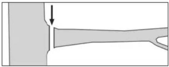
Place the locating surface of the saw against the branch in order to prevent jerky movements of the saw when you begin to cut it. Guide the saw with light pressure from the top to the bottom through the branch.
Watch out for premature breakage of the branch if you have misjudged the size and weight.
natural_image
Diagram showing a mechanical joint or fracture with an arrow indicating direction (no text or symbols present)- Sawing off larger branches:
In the case of larger branches, select a relief cut fi rst of all to ensure that the sawing process is controlled. To do this, saw an incision (a) into the bottom third of the branch (with the upper side of the blade). Then saw from top to bottom towards the fi rst cut (with the underside of the blade) (b).
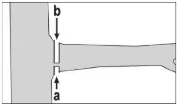
text_image
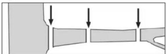
b a- Sawing in sections:
Saw off large or long branches in sections so that you have control over the place where the branch section lands.
natural_image
Diagram showing three rectangular blocks with downward arrows indicating flow or movement (no text or symbols)- Saw the lower branches of the tree off first in order to make it easier for the branches that have been cut off to fall to the ground.
- After the cut is completed, the weight of the saw increases abruptly for the operator, as the saw is no longer supported on the branch. There is a danger that you will lose control of the device.
- You should only pull the saw out of the cut with the saw chain running in order
to avoid jamming.
- Do not saw with the tip of the cutting equipment.
- Do not saw the bulge at the base of the branch because this will prevent the tree from healing.
Cleaning and servicing

Warning! Risk of injury by dangerous moving parts!

Switch off the engine and disconnect the spark plug con- or (0 73) before carrying out maintenance or cleaning work the device.

You should have any repair and maintenance work that is not de- d in this instruction manual carried our Service Centre. Only use origi- rts.

Wear gloves when working with the blade, saw chain and cutter bar.
Perform the following maintenance and cleaning work regularly. This will guarantee long and reliable use.
- Check the device before each use for obvious defects such as loose, worn or damaged parts. Ensure that the screws are firmly in place.
- Do not cut with blunt or worn blades or chains as otherwise you will overload the engine and gears of your device.
- Check the covers and protective devices for damage and correct fi t. Replace these if necessary.
Cleaning
- Clean the device after each use. Clean the motor housing with a damp cloth or a brush. The device must neither be sprayed with water nor be put into water.
- Keep the ventilation slits of the device clean. Use a damp cloth or brush to do this.
- Do not use any cleaning agents or solvents. This could damage the device irreparably. Chemical substances may attack the plastic parts of the machine.
• Always keep the device clean.
After each use of the device, you must
- clean the blade (with an oily cloth);
- oil the cutter bar with an oil can/spray.
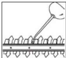
natural_image
Diagram showing a tool interacting with a grid-like structure (no text or symbols)Service intervals
Carefully perform the maintenance tasks listed in the following table on a regular basis. Regular servicing of your unit will extend the life of your equipment. Additionally, you will achieve optimum cutting performance and prevent accidents.
Maintenance intervals table
| Machine part Action Before use | Hours of use | |||
| 10 20 | ||||
| Complete machine | Check condition, replace damaged parts as needed | √ | ||
| Accessible screws and nuts | Check, tighten | √ | ||
| Air filter Clean or replace | √ | |||
| Fuel filter Replace | √ | |||
| Spark plug Clean/adjust/replace | √ | |||
| Fuel hoses Check, replace as needed | √ | |||
| Operating handle Check for function | √ | |||
| Saw chain | Check, oil, regrind or replace if necessary | √ | ||
| Blade bar Check, turn over, clean, oil | √ | √ | ||
| Cutting head | Check correct installation | √ | ||
| Coupling | Check that the device is stationary while idle | √ | ||
| Gears | Lubrication | √ | ||
Sharpening the cutting teeth
Have the saw chain sharpened by a specialist, or proceed in accordance with the operating manual for your saw chain sharpening device (e.g. from Parkside).
Sharpening a saw chain requires some practice. Replacing the saw chain is preferable in case of doubt.
E
Changing the saw chain

Safe use of the device can only be guaranteed with
following saw chain:
Kangxin 3/8.050x44DL
The use of non-approved saw chains can lead to serious injuries.

A hot saw chain contracts again somewhat after cooling down. If
you change the saw chain when it is hot, this can cause damage to the guide bar or the engine, as the saw chain is now too tight against the blade bar.

Never attach a new saw chain onto worn teeth, or onto a damaged or
worn blade.
- Release the nut (48) and remove the chain wheel cover (49).
- Remove the old saw chain (44).
The detailed assembly is described in the section "Assembly - Fitting the saw chain". For tensioning the new saw chain, please refer to the section "Initial start-up - Tensioning the saw chain".
E
Maintaining/turning the blade bar
The blade bar has to be reversed every 8-10 operational hours in order to ensure even wear.
- Release the nut (48) and remove the chain wheel cover (49). Remove the saw chain (44) and the blade bar (1).
-
Check the blade bar (1) for wear. Remove burrs and straighten the guide surfaces with a flat file.
-
Clean the oil passage (45) to ensure fault-free, automatic oiling of the saw chain during operation.
- Turn the blade bar (1) once along its horizontal axis.
- Place the saw chain (44) into the blade groove. Place the saw chain (44) into the chain sprocket (42).
- Place the blade bar (1) and saw chain (44) on the coach screw (43). When the nose (47) on the right below the coach screw (43) sits in the lower round recess on the blade bar, the blade bar is placed correctly.

It is normal for the saw chain (44) to sag.
- Pre-tension the saw chain (44) by turning the screw (46) in a clockwise direction with the mounting key (26).
- Put the chain wheel cover (49) back in position. Tighten the nut (48) of the sprocket cover.
Replacing the spool

Safe use of the device can only be guaranteed with the
PARKSIDE spool. The use of non-approved spools may result in serious injury.
Illustration G:
- Place the device on the ground in a stable position.
- Block the uptake spindle (50) using the hex key (28) as depicted.
- Screw the spool cap (17) clockwise from the uptake spindle (50).
Illustration N:
- Open the spool cap (17) by firmly pressing the quick-release catch (68) inwards on both sides of the spool cap (17), and remove the spool cap cover.
GB MT
-
Place the new spool (69) into the spool cap cover (17) and insert the two ends of the line through the line outlet loop (66). Loosen the two line ends from the grooves (70) on the spool.
-
Place the spool (69) inside the lid of the spool cap (17) and reassemble the lid and base.
i Ensure that the line outlet loops (66) match the two recesses (67) in the spool cap otherwise the cover will not close.
Illustration G:
-
Screw the spool cap (17) anticlockwise back onto the uptake spindle (50).
-
Remove the hex key (28)!
-
Trim the line cord to approx. 15 cm.
N Winding up the spool
As an alternative to a new spool, you can purchase a 2.4 mm-thick, 6 m-long nylon line in specialist shops and wind this yourself onto the spool.

A spare line is already included in the delivery.
- Fold the line in the middle and place the middle of the line in the notch (71) of the spool (69).

Wind up the two ends in the direction of the arrow, which is shown on the topside of the spool.
- Then clamp the end of each line in one of the grooves (70) on the spool (69).

Replacing/adjusting the spark plug

Worn spark plugs, or a spark plug gap that is too large, will lead to a reduction in engine power.
- Switch the engine off.
- Pull the spark plug connector (73) off the spark plug (72).
- Unscrew the spark plug (72) anticlockwise with the enclosed maintenance key (26).
- Check the spark plug gap with the help of a feeler gauge (available from specialised dealers). The electrode air gap must be 0.6-0.7 mm.
- Reset the gap if necessary, by carefully bending the ground/side electrode of the spark plug (72).
- Clean the spark plug (72) with a wire brush.
- Reinsert the cleaned and adjusted spark plug (72) or replace damaged spark plugs (72) with a new spark plug (e.g. spark plug "TORCH L8RTC").
- Reattach the spark plug connector (73).

The spare parts which are to be ordered can be found in the "Spare parts/accessories" section.

Sharpening the line cutter
Never use the device without a string cutter or defective line cutter. There is a risk of injury. If the line cutter blade is damaged, be sure to contact our service centre.

Wear protective gloves in order to avoid cutting yourself.
-
Unscrew the line cutter (18) from the extension (19) of the protective cover (21).
-
Clamp the line cutter (18) in a vice and sharpen the knife with a fl at fi le. File carefully, and always in one direction only.
-
Screw the line cutter (18) back onto the extension (19) of the protective cover (21).

Cleaning/replacing the air filter

Never run the device without an air filter. Dust and dirt may otherwise enter the engine and cause damage to the machine. Keep the air filter clean.
- Loosen the screw (74) on the air filter cover (75) and remove the air filter cover (75) from the air filter housing (77).
- Remove the air filter (76) from the air filter housing (77).
- Clean the air filter (76) with soap and water and allow it to air dry. Never use petrol for cleaning!

Replace the air filter (76) if it is worn, damaged or dirty (see "Spare Accessories").

The grid acts as a spacer and has to be inserted in the air filter housing (77) first, if it falls out when removing the air filter (76).
- Insert the two lugs on the air filter cover (75) into the tabs on the air filter housing (77).
- Fold the air filter cover (75) over the air filter housing (77).
- Fix the air filter cover (75) with the screw (74).

Replacing the fuel filter

Never operate the device without a fuel filter. Change the fuel filter regularly.
- Unscrew the tank cap (55).
- Empty the fuel tank (54) into a suitable vessel.
- Pull the fuel filter (78) out of the tank using a hook and remove it by loosening the small clamp.
- Replace the fuel filter (78) and put the attached suction head back into the tank.
- Close the fuel tank (54) again with the tank cap (55).

Fuel filter specifications:
Connection ∅ 4 mm
Outside diameter: approx. 16 mm

Lubricating the gears
The gear units of the attachments require lubrication after around 10 hours of operation.
Trimmer/brush cutter
- Loosen the screw (79) on the gears with the mounting key (26).
- Insert up to 5 g of commercially-available lubricating grease into the lubrication opening on the gearbox housing.
- Close the gears again using the screw (79).
Adjusting the carburettor
The carburettor has been preconfigured for ideal performance at the factory. If any readjustments are necessary, have the adjustments made by a specialist workshop.

Storage

Perform cleaning and maintenance work before storage.
- Store the device in a dry place, out of reach of children. Store the device in a
GB MT
horizontal position or secured against toppling over.
- Store the 3-tooth blade (15), the pruner attachment and hedge trimmer attachment with the transport protection (11/13/16) provided.
- Empty the oil tank if it will not be used for a prolonged period of time (6-8 weeks).
- Clean the device and accessories carefully before storage.
- Store the device in a dry and dustproof location and out of reach of children.
- Do not wrap the device in plastic bags as moisture and mildew may form.
- Do not lie the device down on the protective cover.
A Transport

Never transport your device while it is operating! Risk of injury!
- During transport, the device must be switched off and the spark plug connector(73) must be disconnected. Do not transport the device when it is idling.
• Always use the transport protection (11/13/16) when transporting. - Always carry the device with the cutting unit pointing backwards using both hands: one on the rear handle (8) and the other on the front round handle (9).
- Do not transport the device upside down, as otherwise fuel might leak out.
- Before transporting between two locations, empty the fuel tank with a petrol suction pump.
Do not empty the fuel tank indoors, near fire or when smoking. Gas vapours can cause explosions or fire.
- Transporting in a vehicle: Secure the device against tipping over and damage. Ensure the device is securely positioned.
Disposal/environmental protection
Do not dispose of waste oil and petrol residues in the sewage system or down the drain.
Dispose of waste oil and petrol remnants in an environmentally friendly way - take them to your local recycling centre.
The device, accessories and packaging should be properly recycled. Machines must not be disposed of with domestic waste.
Drain the petrol tank carefully and drop the device off at a recycling centre. The plastic and metal parts used on your device can be properly sorted according to materials and grades and efficiently recycled.
Please contact our service centre for more information.
Directive 2012/19/EU on waste electrical and electronic equipment: Consumers are legally obliged to recycle electrical and electronic equipment in an environmentally sound manner at the end of its life. In this way, environmentally friendly and resource-saving recycling is ensured.
Depending on the implementation in national law, you may have the following options:
- Return to a shop,
- Hand over to an official collection point,
- Return to the manufacturer/distributor.
This does not affect accessories enclosed with the old devices or tools without any electrical components.
Guarantee
Dear Customer,
This equipment is provided with a 3-year guarantee from the date of purchase.
In case of defects, you have statutory rights against the seller of the product. These statutory rights are not restricted by our guarantee presented below.
Terms of Guarantee
The term of the guarantee begins on the date of purchase. Please retain the original receipt. This document is required as proof of purchase. If a material or manufacturing defect occurs within three years of the date of purchase of this product, we will repair or replace – at our choice – the product for you free of charge. This guarantee requires the defective equipment and proof of purchase to be presented within the three-year period with a brief written description of what constitutes the defect and when it occurred. If the defect is covered by our guarantee, you will receive either the repaired product or a new product. No new guarantee period begins on repair or replacement of the product.
Guarantee Period and Statutory Claims for Defects
The guarantee period is not extended by the guarantee service. This also applies for replaced or repaired parts. Any damages and defects already present at the time of purchase must be reported immediately after unpacking. Repairs arising after expiry of the guarantee period are chargeable.
Guarantee Cover
The equipment has been carefully produced in accordance with strict quality guidelines and conscientiously checked prior to delivery.
The guarantee applies for all material and manufacturing defects. This guarantee does not extend to cover product parts that are subject to normal wear and may therefore be considered as wearing parts (e.g. cutter bar, spool, 3-tooth blade, chain) or to cover damage to breakable parts (e.g. switches). This guarantee shall be invalid if the product has been damaged, used incorrectly or not maintained. Precise adherence to all of the instructions specified in the operating manual is required for proper use of the product. Intended uses and actions against which the operating manual advises or warns must be categorically avoided.
The product is designed only for private and not commercial use. The guarantee will be invalidated in case of misuse or improper handling, use of force, or interventions not undertaken by our authorised service branch.
Processing in Case of Guarantee
To ensure quick handling of you issue, please follow the following directions:
- Please have the receipt and identification number (IAN 446657_2307) ready as proof of purchase for all enquiries.
- Please find the item number on the rating plate.
- Should functional errors or other defects occur, please initially contact the service department specified below by telephone or by e-mail. You will then receive further information on the processing of your complaint.
- After consultation with our customer service, a product recorded as defective can be sent postage paid to the service address communicated to you, with the proof of purchase (receipt) and specification of what constitutes the defect and when it occurred. In order to avoid acceptance problems and additional
costs, please be sure to use only the address communicated to you. Ensure that the consignment is not sent carriage forward or by bulky goods, express or other special freight. Please send the equipment inc. all accessories supplied at the time of purchase and ensure adequate, safe transport packaging.
Repair Service
For a charge, repairs not covered by the guarantee can be carried out by our service branch, which will be happy to issue a cost estimate for you.
We can handle only equipment that has been sent with adequate packaging and postage.
Attention: Please send your equipment to our service branch in clean condition and with an indication of the defect.
Equipment sent carriage forward or by bulky goods, express or other special freight will not be accepted.
We will dispose of your defective devices free of charge when you send them to us.
Service-Center
GB Service Great Britain Tel.: 0800 404 7657
E-Mail: grizzly@lidl.co.uk
IAN 446657_2307
MT Service Malta
Tel.: 80062230
E-Mail: grizzly@lidl.com.mt
IAN 446657_2307
Importer
Please note that the following address is not a service address. Please initially contact the service centre specified above.
Spare parts/accessories
You can obtain spare parts and accessories from www.grizzlytools.shop If you have issues ordering, please use the contact form. If you have any other questions, contact the "service centre" (see page 66). If additional spare parts are required, please refer to the part number in the exploded view.
Item Instructions Item Exploded view Name Order no.
| A 15 I-1 3-tooth blade 13800233 | ||
| A 29 I-15 Shoulder strap 91110269 | ||
| A 17 I-2 Spool cap 91110260 | ||
| A 76 II-40 Air filter | 91106208 | |

Troubleshooting
| Problem Possible cause Remedy | ||
| Device does not start | Tank empty Refuel | |
| Incorrect starting sequence | Follow directions on how to start the engine as described in these instructions | |
| Engine is flooded | Let off throttle, start engine several times, remove, clean and dry the spark plug if necessary | |
| Sooty spark plugs, incorrect ignition gap | Clean, adjust or replace spark plugs | |
| Spark plug connection, wires faulty | Renewal/repair by service centre | |
| Carburettor, carburettor jets dirty, incorrect carburettor mix setting | Have the carburettor cleaned and reset by a specialist workshop | |
| Clogged fuel filter Clean or replace the fuel filter | ||
| Engine runs too fast at idle | Engine cold Warm up slowly | |
| Engine will not run at expected maximum power | Sooty spark plugs, incorrect ignition distance | Clean, adjust or replace spark plugs |
| Dirty air filter Clean or replace air filter | ||
| Carburettor, carburettor jets dirty, incorrect carburettor mix setting | Have the carburettor cleaned and reset by a specialist workshop | |
| Incorrect fuel mixture Refuel according to directions | ||
| Sealing ring in crankcase leaking | Have the fault rectified by a specialist workshop Cylinder, piston rings wo | |
| Incorrect ignition | ||
| Excessive formation of exhaust fumes/smoke | Incorrectly set carburettor mixture | Have a specialist workshop reset the carburettor |
| Incorrect fuel mixture Refuel according to directions | ||
Table des matières
Introduction ......69
text_image
Diagram showing a mechanical or optical setup with labeled points A and B, and directional arrows indicating rotation or movement.natural_image
Pure mechanical component diagram without any text, numbers, or symbolsnatural_image
Diagram showing a mechanical joint or pipe with an arrow indicating direction (no text or symbols present)natural_image
Diagram showing three rectangular blocks with downward arrows indicating flow or movement (no text or symbols)natural_image
Diagram showing a tool interacting with a surface of upward-pointing arrows (no text or symbols present)Intervalles de maintenance
Service-Center....134
Importeur ....134
Storingen oplossen......135
text_image
Diagram showing a mechanical or optical setup with labeled components A and B, and directional arrows indicating motion or force.natural_image
Pure mechanical component diagram without any text, numbers, or symbolsnatural_image
Diagram showing a mechanical joint or bracket with an arrow indicating force or direction (no text or symbols present)• Grotere takken afzagen:
natural_image
Diagram showing three rectangular blocks with downward arrows indicating flow or movement (no text or symbols)natural_image
Diagram showing a droplet interacting with a surface of uniformally spaced objects (no text or symbols)Service-Center......168
Importador ....168
Cadena ....Kangxin 3/8.050x44DL
text_image
Diagram showing a mechanical or electrical component with labeled points A and directional arrows indicating motion or force.natural_image
Pure mechanical component diagram without any text, numbers, or symbolsnatural_image
Diagram showing a mechanical joint or fracture with an arrow indicating direction (no text or symbols present)natural_image
Diagram showing three rectangular blocks with downward arrows indicating flow or movement (no text or symbols)natural_image
Diagram of a mechanical or electrical component with a suspended rod and arrow-like features (no text or symbols)Catena ....Kangxin 3/8.050x44DL
(L_pA) 99,0 dB; K_pA = 1,98 dB
text_image
Diagram showing a mechanical or optical setup with labeled points A and directional arrows, likely illustrating a motion or signal flow.natural_image
Pure mechanical component diagram without any text, numbers, or symbolsnatural_image
Diagram showing a mechanical joint or pipe with an arrow indicating direction (no text or symbols present)natural_image
Diagram showing three rectangular blocks with downward arrows indicating flow or movement (no text or symbols)natural_image
Diagram showing a droplet interacting with a surface, no text or symbols presentService-Center......231
Dovozce....231
natural_image
Diagram of a mechanical or optical setup with labeled points A and directional arrows, no readable text or symbols present.natural_image
Pure mechanical component diagram without any text, numbers, or symbolsnatural_image
Diagram showing a mechanical joint or fracture with an arrow indicating direction (no text or symbols present)natural_image
Diagram showing three rectangular blocks with downward arrows indicating flow or movement (no text or symbols)natural_image
Diagram of a mechanical or electrical component with a rod inserted into a grid-like structure (no text or symbols)Intervaly údržby
Service-Center......262
Dovozca....262
Refaz....Kangxin 3/8.050x44DL
obsluhy (L_nA) 99,0 dB; K_nA = 1,98 dB
text_image
Diagram showing a mechanical or electrical component with labeled points A and directional arrows indicating rotation or movement.natural_image
Pure mechanical component diagram without any text, numbers, or symbolsnatural_image
Diagram showing a mechanical joint or bracket with an arrow indicating force or direction (no text or symbols present)natural_image
Diagram showing three rectangular blocks with downward arrows indicating flow or movement (no text or symbols)natural_image
Diagram showing a droplet interacting with a surface of uniform patterned lines (no text or symbols)Intervaly údržby
natural_image
Diagram of a mechanical or electrical component with labeled points A and directional arrows, no readable text or symbols present.natural_image
Pure mechanical component diagram without any text, numbers, or symbolsnatural_image
Diagram showing a mechanical joint or fracture with an arrow indicating direction (no text or symbols present)natural_image
Diagram showing three rectangular blocks with downward arrows indicating flow or movement (no text or symbols)natural_image
Diagram of a tool interacting with a grid of pins or connectors (no text or symbols present)Service-Center......328
Importer 328
(L_pA) 99,0 dB; K_pA = 1,98 dB
text_image
Diagram showing a mechanical or electrical component with labeled points A and directional arrows indicating motion or force.natural_image
Pure mechanical component diagram without any text, numbers, or symbolsnatural_image
Diagram showing a mechanical joint or fracture with an arrow indicating direction (no text or symbols present)natural_image
Diagram showing three rectangular blocks with downward arrows indicating flow or movement (no text or symbols)natural_image
Diagram showing a tool interacting with a grid of pins or structures (no text or symbols present)Terminy konserwacji
Service-Center......358
Importør 358
Fejlsøgning 359
(L_pA) 99,0 dB; K_pA = 1,98 dB
text_image
Diagram showing a mechanical or optical setup with labeled points A and directional arrows, likely illustrating a motion or force system.natural_image
Pure mechanical component diagram without any text, numbers, or symbolsnatural_image
Diagram showing a mechanical joint or pipe with an arrow indicating force or direction (no text or symbols present)natural_image
Diagram showing three rectangular blocks with downward arrows indicating flow or movement (no text or symbols)natural_image
Diagram of a mechanical or structural assembly with a tool interacting with a grid-like pattern (no text or symbols)Serviceintervaller
| [GCW] Translation of the original EC Declaration of conformity | ||||
| We hereby confirm that the 4-in-1 Petrol Multi Tool model PBK 4 B3 Serial number 000001 - 055000 conforms with the following applicable relevant version of the EU guidelines: | ||||
| 2006/42/EC • 2014/30/EU • 2000/14/EC & 2005/88/EC 2016/1628/EU • 2018/989/EU • 2011/65/EU* & (EU) 2015/863 | ||||
| In order to guarantee consistency, the following harmonised standards as well as national standards and stipulations have been applied: | ||||
| EN ISO 11680-1:2021 • EN ISO 11806-1:2022 • EN ISO 10517:2019 EN ISO 14982:2009 • EN IEC 63000:2018 | ||||
| We confirm the following in accordance with the 2000/14/EC emissions guideline: Sound power level: | ||||
| Hedge trimmer attachment | Pruner attach-ment | Spool at- tachment | 3-tooth blade | |
| guaranteed: 114 dB | ||||
| measured: 109.7 dB 108.8 dB 110.1 dB 109.6 dB | ||||
| Conformity assessment procedure carried out in accordance with Appendix IV / Supply of Machinery (Safety) Regulations 2008: Notified body: NB 0123 , TÜV SÜD Product Service GmbH · Zertifizierstelle · Ridlerstraße 65 · 80339 München · Germany Type-approval certificate no.: M6A 036607 1457 Rev. 00 | ||||
| This declaration of conformity is issued under the sole responsibility of the manufacturer | ||||
| CE Grizzly Tools GmbH & Co. KG Stockstädter Straße 20 63762 Großostheim GERMANY 20.12.2023 | Christian Frank Documentation Representative | |||
Translation of the original EC Declaration of conformity
* The object of the declaration described above satisfies the provisions of Directive 2011/65/EU of the European Parliament and the Council of 8 June 2011 on limiting the use of certain harmful substances in electrical and electronic appliances.
text_image
Technical diagram of a mechanical device with labeled parts, including tools, components, and a clamp.informativ · informative · informatif · informatief · pouczający · informační · informativno informativo · informativan · informatív · informativen · informatívny · информативен · ενημερωτικό
Explosionszeichnung • Exploded Drawing Vue éclatée • Explosietekening • Nákresy explózii Rysunek samorozwijający • Výkres sestavení Plano de explosión • Eksplosionstegning Vista esplosa • Robbantott ábra
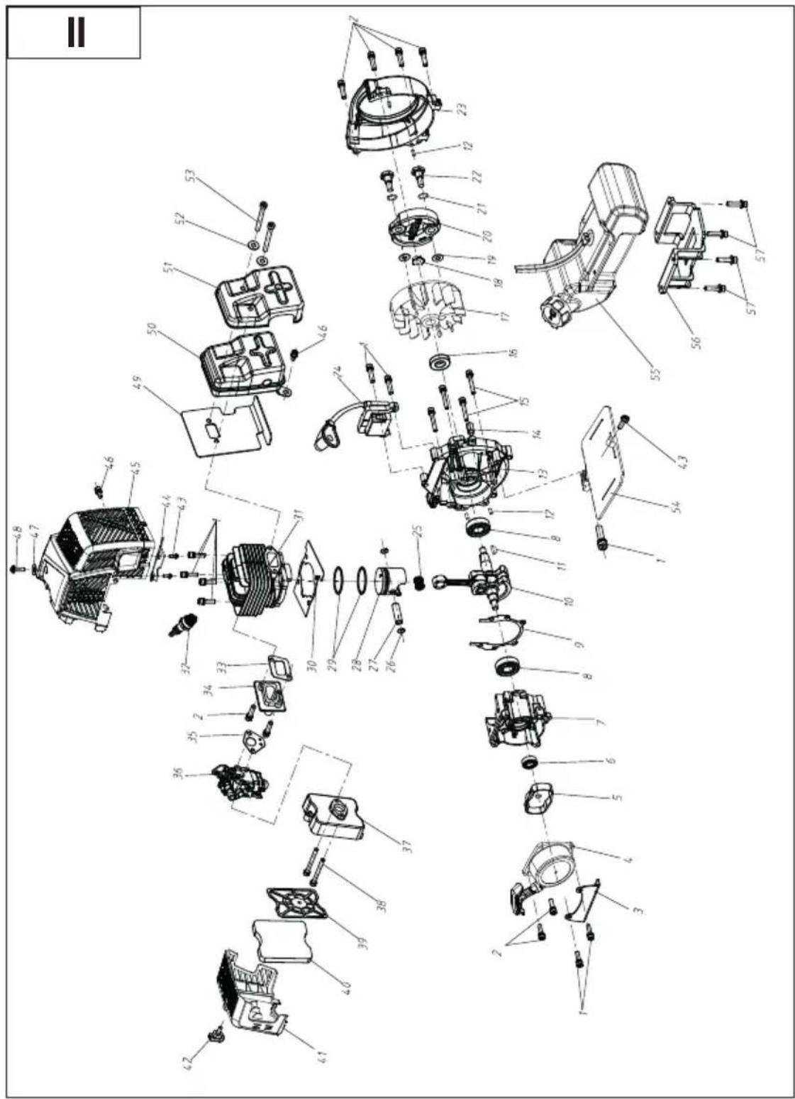
text_image
Exploded view diagram of a mechanical assembly with numbered parts for identificationinformativ · informative · informatif · informatief · pouczający · informační · informativno informativo · informativan
Explosionszeichnung • Exploded Drawing Vue éclatée • Explosietekening • Nákresy explózii Rysunek samorozwijający • Výkres sestavení Plano de explosión • Eksplosionstegning Vista esplosa • Robbantott ábra
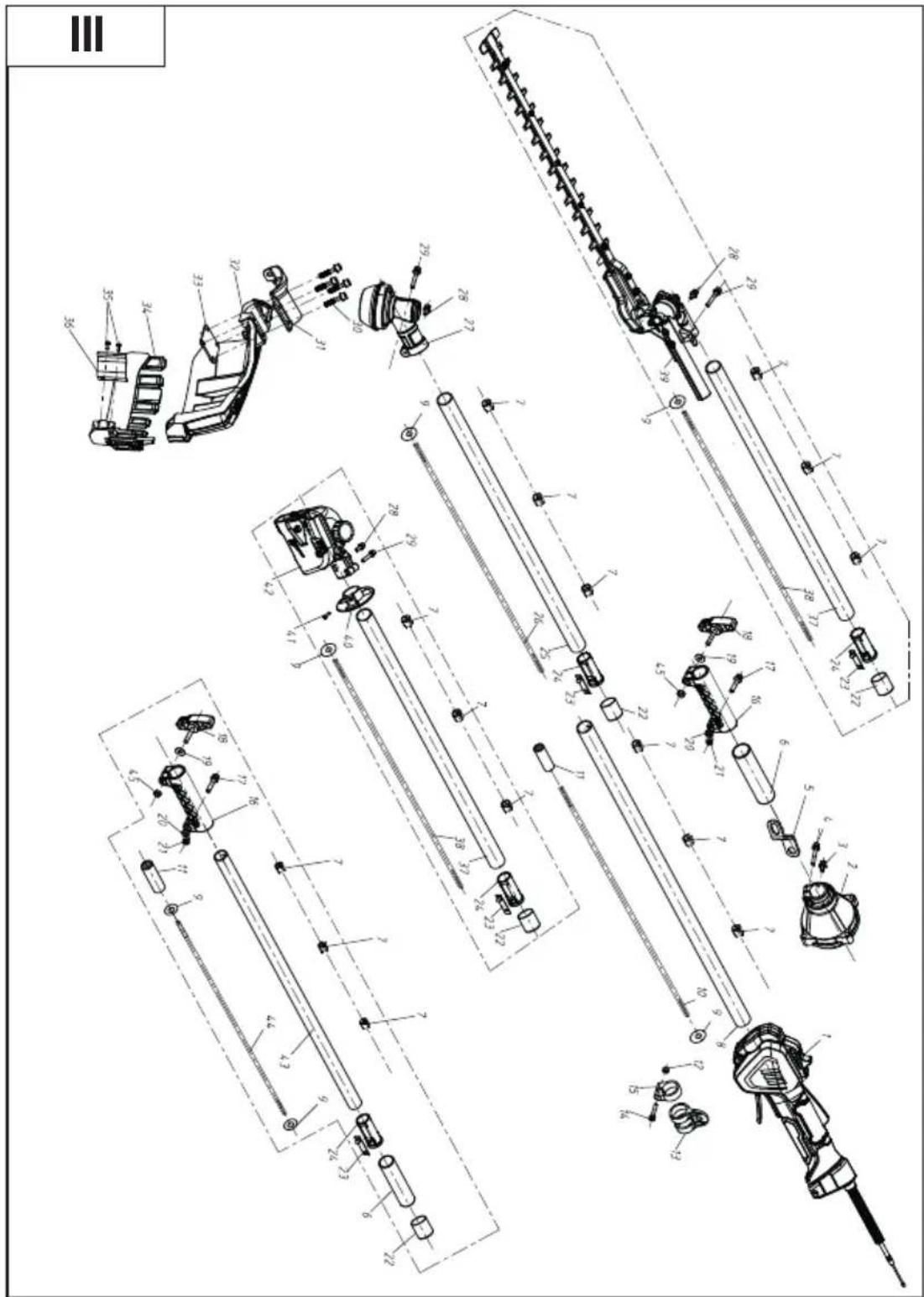
text_image
Technical schematic diagram of a mechanical assembly with labeled components and exploded viewsinformativ · informative · informatif · informatief · pouczający · informační · informativno informativo · informativan

text_image
F 51 52 53 50 15 28
text_image
G 17 50 28
text_image
H 33 54 55 24
text_image
56 25 59 56 57 58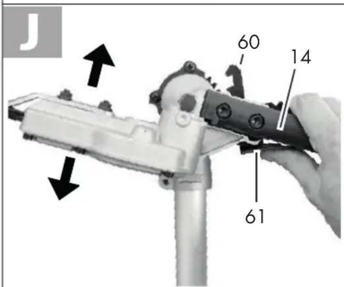
text_image
J 60 14 61
text_image
K 29 30 1 5 31 6

text_image
P 74 75 76 77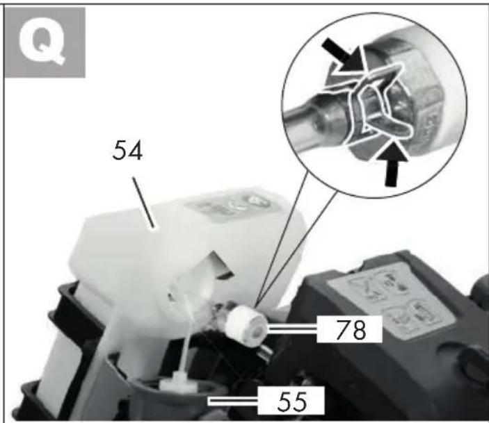
text_image
Q 54 78 55
text_image
R 79 26
text_image
S 10 2 2 2 4 3 5
text_image
FR ©GRIZZLY TOOLS GMBH & CO. KG
text_image
FSC www.fsc.org MIX Paper from responsible sources FSC® C020261
text_image
FSC www.fsc.org MIXTE Papier issu de sources responsables FSC® C020261Erratum
Ersatzteile/Zubehör
Spare parts/accessories
You can obtain spare parts and accessories from www.grizzlytools.shop If you have issues ordering, please use the contact form. If you have any other questions, contact the "service centre" (see page 66). If additional spare parts are required, please refer to the part number in the exploded view.
Item Instructions Item Exploded view Name Order no.
| A | 11 I-12 Transport protection, Pruner 91110267 | ||
| A | 13 I-13 Transport protection, Hedge trimmer 91110268 | ||
| A | 15 I-1 3-tooth blade 13800233 | ||
| A | 29 I-15 Shoulder strap 91110269 | ||
| A | 17 I-2 Spool cap 91110260 | ||
| A | 76 II-40 Air filter | 91106208 | |